1
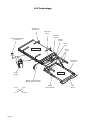
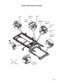
Service Manual for:
CJKA+%(8
CJKA+%(8
Under-Vehicle Lift®
Private Use Wheelchair Lifts
Series 02
DOT — Private Use Lift
“DOT — Private Use Lift” verifies that this platform lift meets only
the “private use lift” requirements of FMVSS No. 403. This lift may
be installed on all vehicles appropriate for the size and weight of
the lift, except for buses, school buses, and multi-purpose
passenger vehicles other than motor homes with a gross vehicle
weight rating (GVWR) that exceeds 4,536 kg (10,000 lb).
www.braunlift.com
WARNING
Man
u
al
"Providing Access to the World"
®
®
Read manual
before installing
or servicing lift.
Failure to do so
may result in
serious bodily
injury and/or
property damage.
TM
TM
Braun UVL Series
International Corporate Hdqrs: P.O. Box 310 Winamac, IN 46996 USA
1-800-THE LIFT ®
(574) 946-6153
FAX: (574) 946-4670
35033
November
2008
Patent #5,305,486
Congratulations
We at The Braun Corporation wish to express our fullest appreciation
on your new purchase. With you in mind, our skilled craftsmen have designed and
assembled the finest lift available.
This manual provides service-related material. Refer to the FMVSS No. 403
Quick Reference Installation Sheet for installation instructions, operating instructions
and maintenance procedures.
Braun UVL Series™ lifts are built for dependability and will provide years of pleasure and independence as long as the lift is installed and serviced as specified by a
Braun certified technician, and the lift is operated by an instructed person.
Sincerely,
THE BRAUN CORPORATION
Ralph W. Braun
Chief Executive Officer
Warranty and Registration Instructions
Immediately upon receiving the lift, examine the
unit for any damage. Notify the carrier at once
with any claims.
Series No.
Model No.
Serial No.
OWNER'S WARRANTY REGISTRATION
NUVL603C
Two warranty/registration cards (shown right) are
protected in a clear envelope and attached to the
lift protective shipping wrap. The sales representative must process one of the cards. The consumer
must fill out the other card and mail it to The Braun
Corporation. A detailed warranty section is provided
in this manual. The warranty cards must be
processed to activate the warranty.
02-00025
PURCHASED FROM
OWNER
DATE INSTALLED
NAME
ADDRESS
CITY
TELEPHONE
STATE
ZIP
TO VALIDATE WARRANTY
REGISTRATION CARDS MUST BE RETURNED TO THE BRAUN CORPORATION.
Sample Warranty/Registration Card
Two Braun Serial No./Series No. identification tags (shown below) are posted on the lift. One
I.D. tag is posted on the left platform side plate (outboard end). A second I.D. tag is located
inside of the pump module. Both I.D. tags provide the product identification information
provided on the warranty/registration card. Record the information in the space provided (or
document on a copy). This information must be provided when filing a warranty
claim or ordering parts.
The Braun Corporation
1-800-THE-LIFT ®
BRAUNMOBILITY.COM®
Model No.
DOT Private Use Lift MODEL#
NUVL603C
Max. Lifting Capacity - 750Lbs.
Series No.
SERIAL NUMBER
02-00025
MFG DATE
11/12/2007
Serial No.
Pump Code
e5*72/245*95/54*0102*00
PATENT
5,305,486
Sample Serial No./Series No. Identification Tag
Cylinder Code
Date of Manufacture
Contents
Troubleshooting and Maintenance
Lift Terminology ............................................................ 2
Switch and Sensor Locations ..................................... 3
Certification Checklist .................................................. 4
Adjustments and Calibration ....................................... 5
LCD Diagnostic Codes ................................................. 6
Floor Level and Inboard Locator Adjustments ..... 7-10
Lubrication Diagram ....................................................11
Maintenance and Lubrication Schedule ............... 12-14
Troubleshooting Diagnosis Chart ......................... 15-18
Notes ............................................................................ 19
Lift Wiring Schematic - Main ..................................... 20
Lift Wiring Schematic - Accessories ........................ 21
Hydraulics
Hydraulics Parts List .................................................. 22
Hydraulics Diagram .................................................... 23
Repair Parts
Pump Module
Pump Module Parts List ....................................... 24
Pump Module Diagram ......................................... 25
Lift Exploded Views
Complete Lift .......................................................... 26
Repair Parts List ................................................... 27
Housing Detail ........................................................ 28
Carriage Detail........................................................ 29
Platform Detail........................................................ 30
Warranty
Braun® Limited Warranty ....................................... 31-33
Notes ............................................................................ 34
Page 1
Lift Terminology
Lift Mounting
Brackets (4)
Chain Drive
Motor
Hydraulic
Cylinder
Inboard
Locator
Hand-Held Attendant's
Control Box
Torque
Tube
Lift Housing
Lifting
Arms
STOW
R
DOO
UP
N
DOW
C
ar
ria
ge
Outer Barrier
Actuator
WA
RN
ING
Push
manu T-han
and ally dle
lock out movein fully
to
Failurbefor
engagplatfo and
resulte to e drivine rm
deplo in lock gplatfo in
unint platfovehicrm
platfoymen
resultrm t. ended rm le.
may
and/o in deploUnint platfo
seriouymenended rm
r prope
s t may
rty bodily
dama injury
Do
ge.
not
rem
ove!
81823
Platform
Pump
Module
Platform Cable-activated
Manual Release System
Inboard
Left
Page 2
Right
Outboard
Rolling
Horizontal Arms
Outer
Barrier
Switch and Sensor Locations
Lift Out
Limit Switch
73950A
Lift Out
Cam
73774
Full Out
Cam
73775
Full Out
Limit Switch
73950A
Below Stow
Limit Switch
73950A
Floor Level
Limit Switch
73950A
Floor Level
Cam
73712
Below Stow
Cam
73712
Outer Barrier
Limit Switch
73950A
STOW
DOOR
UP
N
DOW
WARN
ING
Push
manuaT-hand
and lly le
lock out movein fully
to
Failurbefore
engagplatfo and
resulte to drivine rm
deployin lock gplatfo in
uninteplatfovehiclrm
platfo ment.
nded rm e.
resultrm
may
Uninte platfo
and/orin deploy
seriou
nded rm
prope ment
s
may
rty bodily
damag injury
Do
not
e.
remo
ve!
Inboard
Left
81823
Right
Outboard
Pressure
Transducer
30426
Page 3
Certification Checklist
The following operations and conditions must be functionally verified in order for the lift to be FMVSS
403/404 compliant. If an operation does not function as described or a condition is not met, follow the referenced procedures to correct the problem or contact a Braun Corporation Product Support representative.
• Vehicle movement is prevented unless the lift door is closed, ensuring the lift is stowed.
1. Verify lift stowed signal (pin 9) in the 9 conductor plug on the side of the pump module has a +12 volt
signal.
2. Refer to the interlock installation instructions.
• Lift operation shall be inhibited unless the vehicle is stopped and vehicle movement is prevented.
1. Verify vehicle secure signal (pin 6) in the 9 conductor plug on the side of the pump module has a +12
volt signal.
2. Refer to the interlock installation instructions.
• The platform will not fold/stow when occupied.
- Refer to Platform Sense Calibration.
• The outer barrier will not raise if occupied.
- Refer to Outer Barrier Occupied Calibration procedure
• An audio warning (and visual warning for public use lifts) will activate if the threshold area is occupied
when the platform is a least 1" below floor level.
1. Make sure connectors to threshold mat are properly connected.
2. Call Product Support.
• Lift platform movement shall be interrupted unless the outer barrier is deployed (up).
- Check Barrier Down limit switch, wires and connector.
- Diagnostic LCD should display a value of “1” for OBAR SW when outer barrier is deployed (up).
Page 4
Adjustments and Calibration
Adjustment Procedures
Lift Out Switch: The Lift Out Switch stops inward
travel of the carriage/platform during Stow function
(activated by the housing-mounted Lift Out Cam).
Move cam in to increase inward travel. Move cam
out to decrease inward travel.
Full Out Switch: The Full Out Switch stops outward travel of the carriage/platform during Deploy
(Up/Down) functions (activated by the housingmounted Full Out Cam). Move cam in to decrease
outward travel. Move cam out to increase outward
travel. Carriage rollers must be inside housing a
minimum 1/2". The platform will not raise or lower
until this switch is activated.
Floor Level Switch: See page 6 for procedures.
Stow Switch: The Stow Switch controls the height
of the carriage/platform before it moves inward during the Stow function (activated by the torque tubemounted Stow Cam). Rotate the cam in to decrease
platform height. Rotate the cam out to increase platform height. Adjust cam so lifting arms are aligned.
View the platform position in the housing.
Barrier Down Switch: This platform-mounted
switch prohibits the platform from raising unless the
outer barrier is in the full up position. The Up function is prohibited if the outer barrier detent pin is not
fully engaged also.
Drive Chain Adjustment
In event the drive chain sags 1/2" or more, adjust
tension as detailed. Tighten to eliminate visible sag
but do not overtighten.
1. Remove bottom pan.
2. Pull the manual release cable and lock.
3. Remove adjustment bolt (tensioner) access
cover.
4. Loosen inside jam nut. Secure tensioner and
tighten outside jam nut. Tighten to eliminate visible chain sag but do not overtighten.
5. Lock jam nuts together making sure the tensioner roller is horizontal. Release and push the
manual cable in fully. Ensure platform is locked
by moving the platform in and out until chain
release assembly engages chain.
Carriage Ride Height Adjustment
The carriage horizontal arms move (roll) in and out
of the housing tracks on roller bearings. Following installation or extensive lift operation, clearance
between horizontal arms and tracks may diminish.
The eccentric shaft mounting plate allows height
adjustment.
Remove eccentric plate mounting screw. Using
screwdriver or small rod, rotate the shaft clockwise to
increase carriage height. Rotate the shaft counterclockwise to decrease carriage height. Reinstall
mounting screw in nearest retainer hole. Adjust
left and right side eccentric shafts (screw positions
may vary from side to side). Adjust height such that
horizontal arms do not contact top or bottom of tracks
(align center).
Calibration Procedures
Platform Sense Calibration
1. Place 20 lbs. in the center of the platform.
2. Press UP button on the hand-held pendant to raise
the platform a minimum of 3" above stow level.
3. Press and hold 50# CAL button on control board.
While pressing the 50# CAL button, press and
hold the STOW button on the hand-held pendant.
The platform will lower to stow level, raise slightly,
lower to stow level, and begin inward travel.
Release the 50# CAL button when the platform
begins moving inward. The platform sensing is
now calibrated.
4. After calibration, the LCD screen should read “PF
OCCUPIED” when 50 lbs., or more, are present
on the platform. If 50 lbs. does not activate the
“platform occupied” signal readout, recalibrate with
less weight to lower the “occupied” setting or more
weight to increase the “occupied” setting.
Ground Sense Calibration
1. Press hand-held pendant DOWN switch to lower
platform fully to ground level.
2. While continuing to press the pendant DOWN
switch, press and then release the control board
O_BAR/GROUND LVL button.
3. Release the pendant DOWN switch. Ground
Level sensing is now calibrated.
4. After calibration, the outboard roll stop should
not unfold (down) until the platform is fully on the
ground.
Outer Barrier Occupied Calibration
1. Press hand-held pendant DOWN switch to lower
platform fully to ground level.
2. Once outer barrier is fully unfolded (ramp position),
release the pendant DOWN switch.
3. Press and hold the control board O_BAR/
GROUND LVL button. While holding O_BAR/
GROUND LVL button, press hand-held pendant
UP switch to raise the outer barrier. Be sure to
release O_BAR/GROUND LVL button when outer
barrier reaches approximately half full up (vertical)
position.
4. After calibration, the LCD screen should read
“OUT-BAR OCCUPIED” whenever there is weight
present on the outer barrier.
Page 5
LCD Diagnostic Codes
D6
D3
102
D2
102
D4
U16
103
103
243R
D
C
D6
8.00M
D5
D3
8.00M
102
103
U5
103
103
SOMC1601
V104
103
103
106 E
330
V104
103
D21
C11
C8
V104
U21
C10
U19
V104
VR3
FS11
MAT
5Q6
220
35A
C16
D20
D12
Door
Operator
RL10
IN
NUVL CONTROLLER REV-3.1-1
The Braun Corporation
103
103
R11
V104
103
103
102
V104
102
V104
103
SW2
1
1
R7
2
O_BAR
GROUND LVL
C22
2
6C5
L_OUT
L_IN
103
C2
R6
SW1
R1
50# CAL
R10
R9
OPEN
D13
3
3
103
C3
R4 R2
102
R42
U17
RL11
4
100
VHA
B_UP
R8
102
V104
V104
U22
D10
103
R38
CLOSE
R36
C5
R37
U7
U18
C9
OH
INLK-1
D11
B_DN
U2
C1
R33
ZD3
C15
HAND-2
6H23EM
102
D26
R15 R14
D25
Magnetic
L_DN
D24
C4
U12 C14
L_UP
C105
U8
diag
R32
C21
R26
103
D1
6C5
220
CHA
R16
A
R1
Remote
HAND-1
6H23EM
103
D2
6C5
U3
220
CHA
LIGHT
J1
J2
R29
103
R27
C20
1
102
CONTRAST
2
1
R31
B
2
cycle
102
D4
3
3
C7
U/D
D/S
U15
D23
UP
D8
V104 C6
G
H
I
J
STOW
D7
L U14
K
Lift Devices
OBAR S W 1
103
103
102
B
R13 R20 R19 R18
R39 R5
102
R28
DOWN
D5
102
A
DOOR
D8
R31
C
cycle
diag Button
All basic functions (UP,
DOWN, STOW and
DOOR) should show a
value of 1 when activated
via a controlled input
(Hand-held Pendant,
Magnetic, Remote Entry
or 3rd Station Controls).
D7
OBAR S W 1
V104 C6
To change the LCD display from cycle count to diagnostic
mode, press the “diag” button on the control board (see
illustration at right). When finished, press button again to
return to cycle count mode. When all of the harnesses
are correctly connected to the control board, the values
shown in the chart below will display when the corresponding action is taken. “1” will appear to the right of the switch
or sensor name on the LCD module when activated as
shown. If any other value appears on the LCD screen
during the specific diagnostic procedure, verify that the
correct harness is properly connected to both the control
board and the associated lift harness. Repeat the harness
diagnostic procedure. If an incorrect value is still present
after checking the harness and connections, contact The
Braun Corporation Product Support Department.
5Q6
220
35A
C13
L
C12
R34
IN
H
U20
R25
102
RL1
D15
D17
D14
R3
U9
FS4
FS3
FS5
L_IN
L_OUT
B_UP
B_DN
1
FS6
1
1
1
1
1
1
1
1
1
D16
PUMP
VALVE
1
1
1
MAT SW
= 1 when mat is activated.
DO SW
= 1 when door is full open or pin 3 and pin 4 are jumpered.
= 1 when inboard locator is activated
*(NUVL855C only)
Page 6
ALARM
LIGHT
Moving Up At Floor Moving Down Ground Ground Level
From Stow Level
OB Out
Level
From Stow
FLV SW
*IBAR SW
R40
1
FOUT SW
OBAR SW
D18
ALARM
LIGHT
LOUT SW
D19
FS7
STLV SW
RL2
D9
FS8
MP916
0.010Ω
.5% R
NUVL Control Board
Hand-held Pendant
LCD Display Stowed Moving Out
Of Cassette
FS9
FS10
RL9
VR2
FS2
12V-B
PWR-IN
GND
VR1
RL3
1002
RL4
1802
FS1
R43
R41
1
Floor Level and Inboard Locator Adjustments
Achieving proper floor level
positioning of the platform and
inboard locator requires a combination of Floor Level switch
adjustment and inboard locator
adjustment. Both are factory set
but must be inspected during
installation procedures (will vary
per vehicle application).
Ensure the lift is positioned and
secured as specified on Quick
Reference Installation Sheet (supplied with lift) panels 1 and 2. Adjust the Floor Level switch first
(detailed below). Then, adjust
the inboard locator as detailed
in Inboard Locator Adjustment
Instructions (adjust only if neces-
sary). The inboard locator must
rest properly on the vehicle floor
for wheelchair entry and exit.
Floor Level Switch Adjustment
Adjust the Floor Level switch
first! (before adjusting the inboard
locator)!
The Floor Level switch stops upward travel of the platform during
the Up function (activated by the
torque tube-mounted Floor Level
cam).
Position the bottom of the lift plat-
form 1" above floor level (threshold mat) using the manual op
eration system. Do not operate
the lift with the electric pump during adjustment procedures.
Loosen the clamp securing the
torque tube-mounted Floor Level
cam. Rotate the cam until the
Floor Level switch is activated
(cam depresses switch).
Floor Level Cam
Note: Check the floor level position of the platform and the inboard locator after powering the
pump. Hydraulic pressure may affect platform height slightly. Fine
tuning adjustment (tweaking) of
the Floor Level switch may be
required.
Floor Level Switch
A
Torque Tube
Cam depressing switch.
Page 7
Floor Level and Inboard Locator Adjustments
Inboard Locator Adjustment
Do not adjust
inboard locator linkage rod
Do not adjust inat this time!
board locator linkLinkage rod
age rod. Linkage
adjustment is not
rod adjustment may
required unless
result in lift damage.
extra usable
platform length
is needed. If
the angle of the inboard locator (when in the
vertical position) restricts the usable platform
length for the wheelchair passenger, adjustment of the linkage rod will change the angle.
Inboard Locator
CAUTION
B
Linkage Rod
With the platform at ground level and the
inboard locator in the vertical position, there
should be a minimum of 1” clearance between
the inboard locator and torque tube.
Adjust the inboard locator as detailed in the
following procedures. Then, adjust the linkage
rod as detailed on page 9 (only if necessary).
Manual Operation Systems
2. Position the lift platform below
stow level using the manual operation system. See Photo C.
OPEN
1. Raise the lift platform fully (floor level) using the manual operation system (Manual
Operating Instructions detailed on Quick
Reference Installation Sheet). If the inboard
locator rests properly on the floor, do not adjust the inboard locator. Lower the platform
to ground level. If the angle of the inboard
locator (when in the vertical position), does
not restrict the usable platform length for the
wheelchair passenger, disregard inboard
locator adjustment procedures. See Photo H
on page 9. Refer to the following procedures
if adjustment is required.
VALVE
Hand
Pump
OSE
CL
T-Handle
Release
Cable
WA
RN
ING
Pu
sh
ma T-h
an nuall andle
d
y
loc out mo in ful
to ve
Fa k befor
en pla ly an
ilu
ga
res re to e dri ge tform d
de ult in loc vingplatfo in
plo
k
pla ym unint platfovehicrm
restform ent. ende rm le.
an ult in deploUnintd pla may
d/o se ym en tfo
r pro rio en de rm
pe us bo t mad
rty dil y
da y inj
Do
ma
ge ury
not
.
rem
ove!
8182
3
Figure A
Pump
Handle
Valve
Stow Level
Platform
below
Stow
Level
Lowering the platform will allow access to the cam bolt
securement nut. See Photo E.
C
Page 8
Floor Level and Inboard Locator Adjustments
Inboard Locator Adjustment
3. Remove the 1/4" lock nut securing the lifting arm cam bolt.
See Photos D and E. Do not
remove the bolt.
D
Raise the platform fully (floor
level) using the manual operation system.
Remove the cam securement
bolt (lift inboard locator to relieve pressure on bolt).
Cam Bolt
Allow the inboard locator to rest
on the floor.
Rotate the cam so the cam follower bearing engages the cam
notch (saddle). See Photos F
and G.
1/4" Lock Nut
Reinstall the cam securement
bolt in one of the three lifting
arm holes that best lines up
with one of the nine holes in the
cam. See Photos F and G.
Reposition the securement bolt
lock nut. Note: Lowering the
platform will allow access to
cam bolt. Tighten securely.
E
Cam Notch (Saddle)
Cam Notch (Saddle)
Engaging
Cam Follower Bearing
Slider Block
te Cam
Rota
te Cam
Rota
Rocker
F
Lifting Arm
(3 available holes)
G
Cam
(9 available holes)
Page 9
Floor Level and Inboard Locator Adjustments
Inboard Locator Linkage Rod Adjustment
Do not adjust the
CAUTION
inboard locator
linkage rod unImproper inboard
less extra usable
locator linkage rod
platform length
adjustment may
is needed. See
result in lift damage.
Photo H. If the angle of the inboard
locator (when in
the vertical position) restricts the usable platform
length for the wheelchair passenger, adjustment
of the linkage rod will change the angle.
Linkage rod adjustment affects angle
of inboard locator (vertical position).
Adjust the inboard locator as detailed in the
previous procedures. Then, adjust the linkage
rod as detailed (only if necessary). If the linkage rod is adjusted too long or too short, it will
exceed the travel of the slider block resulting in
damage to the cam follower bearing, the cam
and/or other components.
H
Inboard Locator
1. Position the lift platform below stow level
using the manual operation system. Do
not operate the lift with the electric pump
during adjustment procedures.
2. Loosen the jam nuts at each end. Adjust
rod length as needed. Minimize adjustment. Carefully check the inboard locator
angle and operation using the manual
operation system. Ensure the rod has not
been over adjusted resulting in pressure on
components (damage will result). Tighten
the linkage rod jam nuts.
Page 10
I
Linkage Rod
Lubrication Diagram
Drive Chain and Rollers
LO
Torque Tube
Pivot Points
LO
W
STO
R
DOO
UP
N
DOW
Drive Chain
Release Latch Hydraulic
Cylinder
SG
Eccentric
Pivot
Shaft
Points
Rollers Torque
LO
(bearings) Tube
LO
Pivot
Points
LO
Lifting Arm Carriage
Pivot Points Rollers
(bearings)
LO
LO
Rolling
Horizontal
Carriage Arm
Slot Area
DE
Outer Barrier
Detent Pin
LO
WA
RN
ING
Push
manu T-han
and ally dle
lock out movein fully
to
Failubefor
enga platfo and
resulre to e drivin
ge rm
deplot in lock gplatfo in
unint platfovehicrm
platfoymen
resul rm t. ende rm le.
may
and/ot in deploUnintd platfo
serio ymenende rm
r prope
us t d
rty bodilmay
dama y injury
Do
ge.
not
rem
ove
!
81823
Platform Cable-activated
Manual Release System
Lifting Arm
Pivot Points
LO Inboard Locator
Linkage
Pivot Points
Inboard Locator
LO
Hinge
Pivot Points
LO
Outer Barrier
and
Lower Closure
Pivot Points
LO
See the Maintenance/Lubrication Schedule for recommended applications per number of cycles.
Lubricant
Type
Specified (recommended)
Lubricant
Light Penetrating Oil
LPS2, General Purpose
(30 weight or equivalent)
Penetrating Oil
Stainless Stick
Door-Ease
DE - Door-Ease
Style (tube)
Stick (tube)
Synthetic Grease
Mobiltemp SHC32
SG - Synthetic Grease
(Multipurpose)
LO - Light Oil
Available
Amount
11 oz.
Aerosol Can
1.68 oz.
12.5 oz.
Tube
Braun
Part No.
15807
15806
28598
Page 11
Maintenance and Lubrication Schedule
Proper maintenance is necessary to ensure safe,
troublefree operation. Inspecting the lift for any wear,
damage or other abnormal conditions should be a part
of a regular service program. Simple inspections can
detect potential problems.
The maintenance and lubrication procedures specified in the following schedule must be performed by a
Braun authorized service representative at the scheduled intervals according to the number of cycles. NUVL
Series lifts are equipped with a cycle counter (digital
display built into the electronic control board).
NUVL Series lifts are equipped with hardened pins and
self-lubricating bushings to decrease wear, provide
smooth operation and extend the service life of the lift.
When servicing the lift at the recommended intervals,
inspection and lubrication procedures specified in the
previous sections should be repeated. Clean components and the surrounding area before applying
lubricants. LPS2 General Purpose Penetrating Oil is
recommended where Light Oil is called out. Use of improper lubricants can attract dirt or other contaminants
which could result in wear or damage to the components. Platform components exposed to contaminants
when lowered to the ground may require extra attention. Lift components requiring grease are lubricated
during assembly procedures. When replacing these
components, be sure to apply grease during installation procedures. Specified lubricants are available
from The Braun Corporation (part numbers on previous
page).
All listed inspection, lubrication and maintenance
procedures should be repeated at 750 cycle intervals
following the scheduled 4500 cycle maintenance proce-
750
Cycles
Page 12
dures. These intervals
are a general guideline
for scheduling maintenance procedures and
will vary according to
lift use and conditions.
Lifts exposed to severe
conditions (weather,
environment, contamination, heavy usage,
etc.) may require
inspection and maintenance procedures
to be performed more
often than specified.
WARNING
Maintenance and
lubrication procedures
must be performed as
specified by an
authorized service
technician. Failure to
do so may result in
serious bodily injury
and/or property
damage.
Maintenance Indicator: The Lift Ready green LED
mounted on top of the pump cover will change color
to yellow after every 750 cycles. The yellow LED will
not affect the functions of the lift, but is a reminder to
complete necessary maintenance and lubrication.
Once the lift has been serviced, press the CYCLE button (located below LCD display on the control board)
until the Lift Ready LED changes back to green. The
CYCLE button also clears the lift cycle count (since
last service) but not the lifetime cycle count.
Discontinue lift use immediately if maintenance and
lubrication procedures are not properly performed,
or if there is any sign of wear, damage or improper
operation. Contact your sales representative or call
The Braun Corporation. One of our national Product
Support representatives will direct you to an authorized service technician who will inspect your lift.
Outer barrier and lower closure pivot
points (2)
Apply Light Oil - See Lubrication Diagram
Outer barrier detent pin pivot points (2)
Apply Light Oil - See Lubrication Diagram
Inboard locator hinge pivot points
Apply Light Oil - See Lubrication Diagram
Inboard locator linkage pivot points
Apply Light Oil - See Lubrication Diagram
Lifting arm center and platform pivot
points (bearings at all points)
Apply Light Oil - See Lubrication Diagram
Inspect outer barrier and lower closure
for proper operation
Correct or replace damaged parts.
Inspect outer barrier seal and lower
closure gasket
Resecure, replace or correct as needed
Inspect outer barrier detent pin hairpin
cotter
Ensure hairpin cotter is present and can be removed
and inserted easily. Resecure, replace or correct as
needed.
Inspect lift for wear, damage or any
abnormal condition
Correct as needed.
Maintenance and Lubrication Schedule
750
Cycles
1500
Cycles
Inspect lift for rattles
Correct as needed.
Check drive chain tension.
Pull out and lock manual release cable. Adjust
chain tension as needed. See Drive Chain
Adjustment.
Inspect inboard locator and linkage for:
• Proper operation. Roll stop should rest solidly on
floor providing smooth transition.
• Positive securement
• Wear or damage
Resecure, replace or correct as needed. See
Inboard Locator Adjustment Instructions.
Check carriage ride height in housing
Adjust as needed. See Carriage Ride Height
Adjustment.
Check stow height/lifting arm alignment
Lifting arms should be horizontal, aligned with
each other and aligned with carriage. Adjust as
needed. See Switch Adjustment (Stow Switch).
Inspect wiring harnesses for securement, wear or
other damage
Resecure, replace or correct as needed
Check lower pan securement
Resecure, replace damaged parts or correct as
needed.
Torque tube pivot bearings (4 places)
Apply Light Oil - See Lubrication Diagram
Carriage and eccentric shaft rollers (bearings)
Apply Light Oil - See Lubrication Diagram
Rolling horizontal carriage arm slot area
Apply Door-Ease - See Lubrication Diagram.
Apply to the surface area around both slots and
wipe off excess.
Hydraulic cylinder pivot points (4 per cylinder)
Apply Light Oil - See Lubrication Diagram
Drive chain and chain rollers
Apply Light Oil - See Lubrication Diagram
Drive chain release latch mechanism
Apply Synthetic Grease - See Lubrication Diagram
Deploy lift, remove lower pan and blow out housing. Blow off platform also.
Use compressor and nozzle to remove all debris
from housing. Clean lower pan slot and apply
Antisieze to slot before reinstalling pan.
Deploy lift, remove lower pan and clean housing
tracks
Use clean cloth and solvent to clean tracks.
Clean lower pan slot and apply Antisieze to slot
before reinstalling pan.
Check drive chain tensioner, jam nuts and con
necting link for securement and/or misalignment.
Correct or replace damaged parts and/or relubricate. See Drive Chain Adjustment.
Inspect drive chain release latch mechanism for
proper operation, positive securement, wear or
other damage
Correct or replace damaged parts and/or relubricate.
Inspect platform cable-activated manual release
system (T-handle/cable assembly and carriage
movement)
Ensure T-handle release and cable assembly
operate properly. Ensure carriage can be manually extended and retracted freely.
Page 13
Maintenance and Lubrication Schedule
1500
Cycles
4500
Cycles
Inspect limit switches for securement and proper
adjustment
Resecure, replace or adjust as needed. See
Switch Adjustment.
Inspect carriage, lifting arm and eccentric shaft
rollers (bearings) for wear or damage, positive
securement and proper operation
Correct, replace damaged parts and/or relubricate.
Inspect external snap rings (e-clips):
• Carriage roller bearings (4)
• Lower lifting arm pins (4)
• Eccentric shaft track roller bearing (1)
Resecure, replace or correct as needed.
Inspect lower lifting arm pins for wear or damage,
positive securement and proper adjustment
Resecure, replace damaged parts, lubricate or
correct as needed.
Inspect eccentric shaft pins, bearing mounting
screw, washers and securement hardware for
wear or damage, positive securement and proper
operation
Resecure, replace damaged parts, lubricate or
correct as needed. See Carriage Ride Height
Adjustment.
Inspect torque tube cams for securement, wear or
damage
Resecure, replace or correct as needed.
Inspect housing cam brackets for securement,
wear or damage
Resecure, replace or correct as needed.
Inspect cylinder(s), hoses, fittings and hydraulic
connections for wear, damage or leaks
Tighten, repair or replace if needed.
Inspect power cable
Resecure, repair or replace if needed.
Hydraulic Fluid (Pump) - Check level. Note: Fluid
should be changed if there is visible contamination. Inspect the hydraulic system (cylinder, hoses,
fittings, seals, etc.) for leaks if fluid level is low.
Use Braun 87010R (5606 aviation fluid). Do
not mix with Dextron III or other hydraulic fluids.
Check fluid level with platform lowered fully.
Fill to maximum fluid level indicated on reservoir
(specified on decal). Do not overfill. If fluid
level decal is not present - measure 7/8" from the
bottom of fill tube to locate fluid level.
Inspect lifting arm bushings and pivot pins for visible wear or damage
Replace if needed.
Inspect outer barrier pivot pin mounting bolts (2)
Tighten or replace if needed
Mounting
Check to see that the lift is securely anchored to
the vehicle and there are no loose bolts, broken
welds, or stress fractures.
Decals and Antiskid
Replace decals if worn, missing or illegible. Replace antiskid if worn or missing.
Consecutive Repeat all previously listed inspection, lubrica750 Cycle tion and maintenance procedures at 750 cycle
intervals.
Intervals
Page 14
Troubleshooting Diagnosis Chart
WARNING
Troubleshooting and
repair procedures
must be performed
as specified by authorized service personnel only. Failure
to do so may result
in serious bodily
injury and/or property
damage.
FUNCTION
1.00
NO
OPERATION
2.00
PUMP RUNS
BUT WILL
NOT LIFT
PLATFORM
3.00
PUMP DOES
NOT RUN
WITH MANUAL OVERRIDE OR
HAND-HELD
PENDANT
If a problem occurs with your lift,
discontinue operation immediately! Do not attempt repairs
yourself. Contact your dealer or
call The Braun Corporation. One
of our national service representatives will direct you to an
authorized service repairman who
will inspect your lift.
The cause of the problem can
be determined by locating the lift
function and related symptom in
the Troubleshooting Diagnosis
POSSIBLE CAUSE
Charts. The specific cause and
remedy can then be determined
by process of elimination. A Wiring Diagram, Electrical Schematic, Hydraulic Diagram and
Hydraulic Schematic are provided
to aid in troubleshooting.
A Repair Parts section with exploded views and corresponding
parts lists is also provided. Correct the problem if possible. If the
problem continues, contact The
Braun Corporation.
REMEDY
1.11 Low Battery
Check vehicle battery
1.12 Bad ground
Check for good ground between vehicle chassis
and 3/8” bolt on back of power pack.
1.13 Poor plug connections
Check all plugs for proper contact.
1.14 Blown fuse
Check fuses on P.C. board.
1.15 Circuit Sentry
Manually reset Circuit Sentry (circuit breaker).
1.16 Circuit Breaker
Circuit breaker should automatically reset, otherwise replace.
1.17 Defective Interlock
Check for voltage on gray wire with pink stripes in
interlock plug connected to P.C. board.
2.11 Hydraulic valve open
Flush valve by operating manual override switches
up and down at same time for 4 to 5 seconds
several times.
2.12 Pump mounted horizontal
Power pack must be mounted vertically.
2.13 No oil (low)
Use Braun 87010R (5606 aviation fluid). Do
not mix with Dextron III or other hydraulic fluids.
Check fluid level with platform lowered fully.
Fill to maximum fluid level indicated on reservoir
(specified on decal). Do not overfill. If fluid level
decal is not present - measure 7/8" from the bottom of fill tube to locate fluid level.
3.11 Up Solenoid
Check for power on black wire going from solenoid
to motor.
3.12 Bad power and ground
See 1.00
Page 15
Troubleshooting Diagnosis Chart
FUNCTION
4.00
LIFT WILL
GO UP WITH
OVERRIDE
SWITCH BUT
NOT WITH
HAND-HELD
PENDANT
5.00
LIFT WILL
NOT GO
DOWN WITH
MANUAL
OVERRIDE
OR WITH
HAND-HELD
PENDANT OR
GOES DOWN
SLOWLY
OR DRIFTS
DOWN BY
ITSELF
6.00
LIFT WILL GO
DOWN WITH
OVERRIDE
BUT NOT WITH
HAND-HELD
PENDANT
7.00
LIFT WILL NOT
GO OUT WITH
HAND-HELD
PENDANT
8.00
LIFT WILL NOT
GO OUT WITH
OVERRIDE OR
HAND-HELD
PENDANT
9.00
LIFT WILL NOT
STOW WITH
HAND-HELD
PENDANT
Page 16
POSSIBLE CAUSE
4.11 Outer Barrier switch is not
activated or defective.
4.12 Full Out switch is not activated or defective.
4.13 Hand-held pendant not working properly.
REMEDY
Check diagnostic LCD for Outer Barrier switch status. Barrier is down or barrier release pin partially
out. See Outer Barrier Occupied Calibration on
page 5. Replace switch as necessary.
Check diagnostic LCD for Full Out switch status.
Adjust or replace switch as necessary.
Check for hand-held pendant illumination and
continuity of the switches. Verify Door Open switch
is functioning correctly.
5.11 Hydraulic down valve bad
Check for power on red wire from P.C. board to
Down solenoid when pushing override button or
hand-held pendant button. Replace if necessary.
5.12 Dirty down valve (clogged)
Flush valve by operating Up & Down manual
override buttons at same time for 4 to 5 seconds
several times.
6.11 Full Out switch out of adjustment or defective.
Check diagnostic LCD for Full Out switch status.
Adjust or replace switch as necessary.
6.12 Door Full Close switch out of
adjustment or defective.
Check switch for proper operation/adjustment.
Adjust or replace switch as necessary.
7.11 Missing shunt
Verify shunt (jumper) is located in the Door Operator 4-conductor jack (jumper pins 3 & 4) on the
control board when door operators are not used.
7.12 Door Open switch out of adjustment or defective
Check switch for proper operation/adjustment.
Adjust or replace switch as necessary.
8.11 Poor plug connections
Check harness connections A1, A2, B1 and B2
8.12 Bad in/out motor
Check power at motor. Replace motor if necessary.
8.13 Bad power and ground
See 1.00
9.11 Stow switch out of adjustment
or defective.
Check diagnostic LCD for Stow switch status.
Adjust or replace as necessary.
9.12 Platform is occupied or out of
calibration.
Remove weight from platform. See Platform
Sense Calibration on page 5.
Troubleshooting Diagnosis Chart
FUNCTION
POSSIBLE CAUSE
REMEDY
10.11 Poor plug connections
Check harness connectors A1 and A2, E1, N1,
N2, E1, F1 and F2.
10.12 Faulty barrier actuator motor or
actuator out of adjustment
Check power at motor. Adjust or replace actuator
if necessary.
10.13 Bad power and ground
See 1.00
11.11 Faulty Outer Barrier switch
Check diagnostic LCD for Outer Barrier Switch
status. Adjust or replace switch as necessary.
11.12 Barrier occupied
Remove weight from barrier. See Outer Barrier
Occupied Calibration on page 5.
12.00
BARRIER
OPERATES
WITH OVERRIDE SWITCH
BUT WILL NOT
GO DOWN WITH
HAND-HELD
PENDANT
12.11 Faulty Pressure Transducer
Check Pressure Transducer. Adjust or replace
as necessary. See Ground Sense Calibration on
page 5.
12.12 Stow switch out of adjustment or defective
Check diagnostic LCD for Stow switch status.
Adjust or replace as necessary.
12.13 Full Out switch out of
adjustment or defective
Check diagnostic LCD for Full Out switch status.
Adjust or replace as needed.
13.00
SWITCHES
DO NOT
CHANGE
STATE IN
DIAGNOSTIC
MODE
13.11 No power going to switches
Check power on connector A1, pins 1 and 2.
13.12 Faulty wiring
Check continuity of wires from switches to connector
A2.
13.13 Faulty connections
Check for proper connections on each switch and
on each connector on the harnesses. Replace contact if necessary. See diagram on following page.
14.11 Faulty wiring
Check for proper wiring to door openers.
15.11 Lift Out switch out of adjustment
or defective
Lift not stowed fully. Adjust lift out switch or
replace.
10.00
BARRIER WILL
NOT OPERATE
UP OR DOWN
WITH HANDHELD PENDANT
OR OVERRIDE
SWITCHES
11.00
BARRIER
OPERATES WITH
OVERRIDE
SWITCH BUT
WILL NOT GO
UP WITH HANDHELD PENDANT
14.00
DOORS
DO NOT
OPEN
15.00
DOORS
DO NOT
CLOSE
Page 17
Troubleshooting Diagnosis Chart
CONTACT REMOVAL
1. Remove orange wedge using
needle nose pliers or a hook shaped
wire to pull wedge straight out.
Page 18
2. To remove the contacts, gently pull
wire backwards, while at the same
time releasing the locking finger by
moving it away from the contact with
a screwdriver.
3. Hold the rear seal in place, as
removing the contact will displace
the seal
NOTES
This page intentionally left blank.
Page 19
Lift Wiring Schematic - Main
SW PWR
IGN PWR
BELOW STOW
FULL OUT
NOT FULL OUT
LIFT OUT
BAR DN
GND SENS
SAFETY
FLOOR IN
FLOOR LVL
RD
GN
OR
BU
GN / BK
OR / BK
BU / BK
BK / W
BK
WH
RD / WH
GN / WH
BU / WH
BK / RD
NOT USED
NOT USED
NOT USED
NOT USED
WH / RD
OR / RD
BU / RD
RD / GN
RD / WH
GN / WH
BU / WH
BK / RD
NOT USED
NOT USED
NOT USED
NOT USED
WH / RD
OR / RD
BU / RD
RD / GN
1
1
2
2
3
3
4
4
5
5
6
6
7
7
8
8
9
9
10 10
11 11
12 12
BK
WH
RD
GN
SW PWR
IGN PWR
BELOW STOW
FULL OUT
LIFT OUT
BU
LIFT OUT
BAR DN
GND SENS
SAFETY
INBRD BAR
FLOOR LVL
BAR UP PWR
BAR DN PWR
MOT OUT PWR
MOT IN PWR
MOT IN PWR
MOT OUT PWR
BAR DN PWR
BAR UP PWR
RD / BK
GN / BK
OR / BK
BU / BK
BK / WH
RD / WH
GN / WH
BU / WH
BK / RD
WH / RD
OR / RD
BU / RD
RD / GN
BAR DN
GND SENS
SAFETY
INBRD BAR
FLOOR LVL
BAR UP PWR
BAR DN PWR
MOT OUT PWR
MOT IN PWR
MOT IN PWR
MOT OUT PWR
BAR DN PWR
BAR UP PWR
GN
OR / BK
BU / BK
BU
RD / BK
RD
GN / BK
BK / WH
RD / WH
GN / WH
BU / WH
BK / RD
WH / RD
OR / RD
BU / RD
RD / GN
RD / WH
GN / WH
BU / WH
BK / RD
WH / RD
OR / RD
BU / RD
RD / GN
POWER PACK / LIFT HOUSING
HARNESS #34425A-1200
#32426A
E2
E1
BK
HAND
PENDNT
NOTE: SEE LIFT ACCESSORY
ELECTRICAL SCHEMATIC FOR
OPTIONAL COMPONENTS.
1
2
3
4
5
6
P2
BK
RD
NOT USED
NOT USED
DESCRIPTION
#73908A
CONNECTORS
10
9
8
7
6
5
4
3
2
1
BAT.
RD
MOTOR
SOLENOID
GN / WH
BU / RD
RD / WH
RD / GN
RD
W
+
-
BK
OR / RD
WH
YL / WH
DOWN
SOLENOID
RD
#34420A
RD
GROUND
WH
WH
BK
GROUND
PUMP
M
RD
RD
(LIFT STOWED SIGNAL +12V OUTPUT)
BEEPER
YL / LT BL
LED
RD
OR / RD
GY / RD
PRESSURE
TRANSDUCER
#35089A
DIODE
GY / RD
SOLENOID
BK / RD
BK / RD
BU / WH
RD / WH
GN / WH
NC
BEEPER
ALARM
OR / RD
BU / WH
WH / RD
4
3
2
1
4
3
2
1
T2
WH
RD
BK
AUX.
MICROSWITCH
ALARM
B2
LIGHT
U2
VALVE
PUMP
GND
12V
BAR DN
BAR UP
LIFT OUT
LIFT IN
POWER-IN
2 2
1 1
1 1
2 2
GY / PK
LIFT POWER SWITCH
PUMP GROUND
INTERLOCK 1
3
2
1
MAT
RD / WH
C
WAKE UP
12V INPUT
HIGH OUTPUT
LOW OUTPUT
RD
SWITCH
DK BU
WH
RD
BK
#33491A
NO
RD / WH
LT GN / GN
WH
RD
BK
DOOR OPERATOR
1 1
2 2
BK
RD
CIRCUIT
BREAKER
X1
A
B
C
30
87A
BK
N2
A
B
C
1
2
3
4
NUVL
PC
BOARD
#34564A
INTERLOCK 2
GROUND
1
2
3
4
5
6
7
8
9
NOT USED
OR
BU
NC
1
2
3
4
MAGNETIC ENTRY
1
2
3
4
5
6
7
8
9
N1
BAR DN
SW PWR
RD
BK
1
2
DASH SW
DOOR/STOW
X2
O2
1
2
RELAY
INTERLOCK
RD
BK
85
+
BAR UP PWR
BAR DN PWR
86
87
-
O1
RD
BK
OR
BU
BK
RD
F2
M
WH
C
BK
RD
MOTOR
M
BAR DN
NO
4
3
2
1
V2
WH
BK
#34422A
RD
BARRIER ACTUATOR
MOTOR
3
2
1
#33487A
GN
OR
(VEHICLE SECURE SIGNAL +12V INPUT)
FULL OUT
NOT FULL OUT
BELOW STOW
CARRIAGE / PLATFORM
HARNESS #73930A
DK BU
GY / PK
YL / WH
THRESHOLD
MAT
GN / BK
GN
OR
RD
4
3
2
1
4
3
2
1
1 1
2 2
CIRCUIT BREAKER
OR / BK
YL / WH
RD
BU / BK
3
2
1
BATTERY
CHASSIS GROUND
BK / WH
CHIP
COUNTER
DASH SW
UP/DN
#34566
J2
1
2
3
4
5
6
NOT USED
RD
BK
GN
OR
BK
SYMBOL
BK
WH
RD
BK
SW PWR
BAR DN
BAR DN PWR
BAR UP PWR
1
2
3
4
5
6
DOOR OPEN
SWITCH
KEY
M1
L1
LIGHT
REMOTE ENTRY
GY / PK
BK
J4
1
2
3
4
5
6
1
2
3
4
5
6
M2
A
B
C
A
B
C
YL
DK.BU
BK
DK.GN
OR
A
B
C
A
B
C
L2
NOT USED
GN / BK
BK
OR
DK.GN
BK
DK.BU
YL
RD
BK
WH
RD
BK
NC
JUNCTION
1
2
3
4
YL
DK.BU
BK
DK.GN
OR
#33495A
IGN PWR
SW PWR
LIFT OUT
FLOOR LVL
FLOOR IN
SAFETY
GND SENS
FULL OUT
NOT FULL OUT
BELOW STOW
1
2
3
4
P4
#100044-001
WH
RD
BK
RD
BK
NC
K1
OR / BK
NOT USED
BK
BU / BK
NOT USED
BK
BK / WH
NOT USED
BK
WH
C
A
B
C
#31710A
A
B
C
A
B
C
J1
I1
H1
NOT USED
BU
WH
BU
GN / BK
OR / BK
BU / BK
BK / WH
BK
WH
OR
GN
RD
BK
RD / BK
GN / W
RD / WH
A
B
C
A
B
C
A
B
C
A
B
C
G1
C
K2
J2
A
B
C
H2
NO
WH
A
B
C
RD
WH
RD
BK
WH
RD
BK
G2
STOW
NO
HAND - 2
BK
RD / BK
GN / WH
RD / WH
RD
GN
OR
BU
GN / BK
OR / BK
BU / BK
BK / WH
BK
WH
BK
LIFT DEVICES
FULL OUT
NOT USED
R (-OUT)
BK (+IN)
NC
BK
NC
#75960NA
C
RD
BK
C
WH
HAND - 1
NO
STOW
COM
FLR LVL
A
B
C
FLOOR LVL
WH
NOT USED
BK (+IN)
R (-OUT)
LIFT OUT
NO
F1
A2
A
B
C
SW PWR
BAR DN
BAR DN PWR
BAR UP PWR
BELOW STOW
FULL OUT
NOT FULL OUT
LIFT OUT
GND SENS
SAFETY
FLOOR IN
FLOOR LVL
SW PWR
IGN PWR
LIFT HOUSING / CARRIAGE
HARNESS #73920A
SHUNT
RD
WH
STOW / GND SENS
Y2
M
BK
RD / WH
GN / WH
RD / BK
BK
#31235A
IN-OUT
MOTOR
OR
B 1
A 2
BK
RD / BK
GN / W
RD / WH
RD
GN
OR
BU
GN / BK
OR / BK
BU / BK
BK / W
BK
WH
BK
OR
WH / RD
OR / RD
D2
SW PWR
IGN PWR
BELOW STOW
FULL OUT
1
2
GN / WH
RD / WH
RD / BK
D1
BU / WH
BK / RD
BK
WH
RD
GN
NOT USED
BU
NOT USED
RD / BK
GN / BK
OR / BK
BU / BK
BK / WH
1
1
2
2
3
3
4
4
5
5
6
6
7
7
8
8
9
9
10 10
11 11
12 12
BK/WH
GN/BK
RD
NOT USED
RD/BK
BU
BU/BK
OR/BK
GN
WH
BK
NOT USED
BK
RD / BK
BK
WH
RD
GN
OR
BU
NOT USED
RD / BK
GN / BK
OR / BK
BU / BK
BK / WH
SERVICE / INTERLOCK LED
BK
W
E 12
L 11
D 10
9
H
8
F
7
C
6
I
G
5
4
B
J
3
2
K
1
A
BK
RD
GN
OR
BU
GROUND
BK
HYDRAULIC
PUMP MOTOR
RD
CIRCUIT
SENTRY
BATTERY
GROUND
Page 20
U
Li nfo
Sc ft ld
he Wi fo
-M m rin r:
ai at g
n ic
Lift Wiring Schematic - Lift Accessories
#33496KS REMOTE, RECEIVER & HARNESS
#86476 REMOTE & RECEIVER
#86483
UP
DOWN
STOW
DOOR
CLOSE
#86477
THE BRAUN
CORPORATION
10
9
8
7
6
5
4
3
2
1
RD
YL
OR
WH
GN
BU
BK
#33496A
BK
BU
WH
GN
YL
RD
OR
12
11
10
9
8
7
6
5
4
3
2
1
12
11
10
9
8
7
6
5
4
3
2
1
86478
TAILLIGHT MAGNETIC SWITCHES-FORD
#33576K
RD
B
A
E
L
D
H
F
C
I
G
B
J
K
A
CLOSE
MAGNET
WH
HAND PENDANT 25’ EXTENSION
WH
BK
RD
GN
YL
BU
1
2
3
4
5
6
1
2
3
4
5
6
3RD
STATION
UP/DN
1
2
3
S N
BK
3RD
STATION
DOOR/STOW
3
2
1
STOW
RD
REMOTE ENTRY
1
2
3
4
5
6
#32196KS
#25564A
BK
RD
GN
UP/DOWN
DOWN
STOW
GN
RD
BK
DOOR/STOW
1
2
3
4
3
2
1
3
2
1
DOOR
DOOR CUT OUT ADAPTER
#31934A
TO DOOR
OPERATOR
2
1
BK
RD
1
2
WH
GN
BK
RD
WH
GN
1
2
3
4
4
3
2
1
4
3
2
1
GN
BN
YL
WH
#33574A
NOT USED
BN
GN
YL
NOT USED
WH
6
5
4
3
2
1
6
5
4
3
2
1
NOT USED
BK
BK
BK
NOT USED
WH
S N
BK
DOWN
RD
MAGNET
WH
S N
MAGNETIC ENTRY
BK
DOOR OPERATOR
NUVL
PC
BOARD
#34564A
WAKE UP
12V INPUT
HIGH OUTPUT
LOW OUTPUT
INTERLOCK 1
4
3
2
1
1
2
MAT
3
2
1
2
1
GND
12V
LIGHT
ALARM
VALVE
PUMP
INTERLOCK 2
POWER-IN
BAR DN
BAR UP
LIFT OUT
LIFT IN
UP
HAND - 2
3RD STATION CONTROL
MAGNET
WH
10
9
8
7
6
5
4
3
2
1
WH
BK
RD
GN
YL
BU
HAND - 1
1
2
3
4
5
6
#73947N-2500
LIGHT
LIFT DEVICES
KEY
SYMBOL
DESCRIPTION
4
3
2
1
1
2
1 1
2 2
1
2
JUNCTION
PLATFORM
LIGHTS
RD
BK
U2
SWITCH
RD
MAGNET
S N
MAGNETIC SWITCH
BK
#34423A
Page 21
LAMP
Hydraulic Parts List
Item
Qty.
Description
Part #
1
1
Pump Assembly (M259 with Reservoir/with Back-up pump)
87060
2
1
Motor, Pump - 12 Volt
3
1
Valve, “Down” (with Solenoid)
14901
4
1
Clamp, Reservoir - H-48
17069
5
1
Reservoir Replacement Kit (Includes Item #10)
6
1
O-Ring (only), Hand Pump Mounting
17351
7
1
Hand Pump (Backup) with O-Rings (Includes Item #6)
87065
8
3
Screw, 1/4-20 x 1 3/4”, Allen Head
17351
9
1
Handle with Grip
10
1
Fitting, 3/8” Male NPT x 3/8” Barbed
87618
11
2
Clamp, Hose - 5/8” O.D. - Worm Drive
84325
12
1
Tubing, 3/8” x 5/8”, Tygothane - Clear
82066R012
13
1
Plug, 3/8” Plastic Hose
81580
14
1
Fitting, 90°-1/8” Male Pipe x 1/8” Barbed
87563
15
1
Tube, 1/4” O.D. x 1/8” I.D. - Plastic
16
1
Plug, 1/8” Plastic Tube
81583
17
1
Adapter, 1/4” Male NPT x 7/16-20 Male JIC 37°
10130
18
1
Hose Assembly, 1/4” x 154” - Female Swivel 7/16-20 JIC 37°
19
1
Fitting, 90° - 7/16-20 Male JIC 37° x 1/4” Male NPT
87569
20
1
Coupling, Hydraulic Quick Connect x 1/4” Female NPT
87614
21
1
Nipple, Hydraulic Quick Connect x 1/4” Female NPT
87615
22
1
Nut, 9/16-18, Hex Jam
83077
23
1
Fitting Assembly, Bulk Head
24
1
Hose Assembly, 1/8” x 60” - Female Swivel 7/16-20 JIC 37°
25
1
Fitting, 90° - 9/16” Male O-Ring x 7/16-20 Male JIC 37°
87622
26
1
Valve, Flow Control
87049
27
1
Adaptor, Hydraulic Internal
87560
28
1
Fitting, Tee - 1/4” Male NPT - 1/4” Female NPT - 1/4” Male NPT
26786
29
1
Fitting, 7/16” Female O-Ring x 1/4-18 NPT Male
29305
30
1
Switch, Pressure Transducer
30426
31
1
Fitting, 90° - 1/4” Female NPT Swivel x 7/16-20 O-Ring
26789
32
1
Cylinder, UVL Retracting
33
1
Clamp, Hose - Solenoid Mounting
29663
34
1
Solenoid, Up - Trombetta
31129
35
1
Diode Assembly, Up Solenoid
Page 22
14785-IS
88188K
17206A
81557R014
32785A-154
73777A
16004A-060
87055N
73906A
Hydraulic Diagram
1
33
34
35
13
11
24
2
12
9
Arrow must
face pump
25
30
7
29
26
11
27
31
28
8
3
10
6
32
16
4
14
5
15
23
22
21
20
17
19
18
Page 23
Pump Module Parts List
Item
Qty.
1
2
3
4
5
6
7
8
9
10
11
12
13
14
15
16
17
18
19
20
21
22
23
24
25
26
27
28
29
30
31
32
33
34
35
36
37
38
39
40
41
42
43
44
45
46
47
48
49
50
51
52
53
54
55
56
1
1
1
1
1
1
1
2
1
1
1
1
1
1
1
1
1
2
1
1
1
1
2
4
4
5
1
1
1
1
1
3
1
1
7
2
1
1
1
1
1
1
1
2
1
1
1
1
1
1
1
1
2
2
2
2
Description
Pump Assembly, M259
Adapter, 1/4” Male NPT x 7/16-20 Male JIC 37°
Hose Assembly, 1/4”- F. Swivel 7/16-20 JIC 37°
Fitting, 90° - 7/16-20 Male JIC 37° x 1/4” Male NPT
Coupling, Hydraulic Quick Connect x 1/4” Female NPT
Fitting, 3/8” Male NPT x 3/8” Barbed
Tubing, 3/8” x 5/8”, Tygothane - Clear
Clamp, Hose - 5/8” O.D. - Worm Drive
Plug, 3/8” Plastic Tubing
Fitting, 90°-1/8” Male Pipe x 1/8” Barbed
Tube, 1/4” O.D. x 1/8” I.D. - Plastic
Plug, 1/8” Plastic Tube
Clamp, Hose - Solenoid Mounting
Solenoid, Up - Trombetta
Diode Assembly, Up Solenoid
Diode Assembly, Down Valve Solenoid
Terminal, 14/16 Gage Male Spade - 1/4” Fully Insulated
Jumper Assembly, 12 Gage x 4”
Eyelet, 5/16” Insulated - Red
Weldment, Bracket - PC Board Mounting
Circuit Breaker, 20 Amp - Self Reset
Clip, Cable - 7/16” Plastic
Screw, 10-32 x 3/8”, Pan Head Philips, Thread Cutting
Standoff, .25” PCB - Nylon
Screw, #6 x 3/8”. Self Tap, Flat Head
Bumper, 1/2” Dia. x 1/4” Tall - Rubber
Electrical Board Assembly w/Program Chip
Beeper, Constant - High Output
Edge Liner, 1/8” x 6”, Q-Trim
Edge Liner, 1/8” x 4”, Q-Trim
Washer, .328” x .562” x .042”
Screw, 5/16-18 x 1/2”, Serrated Washer Head, Hex
Plate, Power Pack Mounting
Bracket, Power Pack Mounting ✘
Screw, 1/4-20 x 3/8”, Pan Head Phillips ✘
Washer, Lock - 1/4” External Tooth ✘
Lamp, Bicolored LED Panel
Fitting, Strain Relief - Liquid Tight
Switch, Toggle
Harness, Interlock
Plate, Interlock Plug / Cover Reinforcement
Harness, Lift Interlock Connection
Harness, Service / Power Indicator
Rivet, Pop, 1/8” Dia. x .188/.250”
Cover, UVL Power Pack w/Decals ✘
Hand Pendant Assembly, NHTSA NUVL ✘
Harness, Alarm
Ground Cable - Black
Screw, 5/16-18 x 3/4”, Serrated Washer Head, Hex
Harness, Power
Harness, Pump / Valve
Handle, Back-up Pump ✘
Clamp, Spring - Pump Handle ✘
Screw, #10-32 x 3/8”, Flat Head - Phillips ✘
Washer, #10 Flat ✘
Nut, #10-32, Hex ✘
Part #
87060
10130
32785A-154
87569
87614
87618
82066R012
84325
81580
87563
81557R014
81583
29663
31129
73906A
73907A
78036
73943A
86267
73824W
16453
15777
82755
86739
82764
82064
34564A
33251
13910R006
13910R004
83583
82881
73822N
73825
82769
83588
30728
30753
12185
33495A
31345
35089A
31235A
84249
73820RNA-02
32426A
34420A
68874
32464
33491A
33487A
17206A
12350
82767
11541
11542
✘ Indicates items available for replacement part purposes only. These items are not included with replacement pump
modules.
Page 24
Pump Module Diagram
13
46
OW
ST
DO
OR
7
UP
DO
WN
8
9
12
53
8
14
55
6
37
11
WH
51
56
52
TO
CIRCUIT
SENTRY
1
33
53
18
39
49
32
10
35
17
RD
38
48
TO
DOWN
SOLENOID
15
16
19
TO
DOWN
SOLENOID
56
55
18
36
35
LIFT
STOWED
SIGNAL
(OUTPUT)
35
40
45
34
42
41
50
25
VEHICLE
SECURE
SIGNAL
(INPUT)
21
25
28
23
22
54
2
38
24
31
BK
TO
PUMP
GROUND
47
44
24
5
43
RD
25
26
4
24
32
54
27
29
3
30
20
24
35
35
Page 25
Pu Un
m fo
E x p ld
p M fo
V lod od r:
ie e u
w d le
Complete Lift Exploded View
39
39
39
104
85
39
39
13
105
39
110
106
109
38
38
38
38
38
132
70
70
38
133
38
38
70
38
38
71
69
61
72
39
14
2
38
15
14
9
10 13
76
86
6
76
76
2
100
12
1
88
39
101
116
3
97
39
17
31
54
30
99
29
103
107
98
107
39
96
127
65
32
112
67
129
7
49
39
9
11
38
13
25
20 26
21
26
23
24
64
45 63
65
39
56
39
5
59
125
126
24
118
89
114
117
119
90
82
73
43
131
55
120
33
60
39
21
22
26
60 39
39
56
42
21
27
34
22
26
84
35
27
58
40
34
49 49
51
50
41
56
51
52
50
52
24
21
37
24
48
94
92
91
37
56
56
24
28
24
111
24
41
39
53
83
28
35
19
23
81
55
121
124 122
123
57
57
134
108
62
66
45
64 63
47
128
26
60
49
5
20
130
114
87
66
45
46
68
45
62
75
78
74
24
115
63
8
39
134
46 47
64
29
99
4
44
44
77
57
16
2
114
77
113
60
18
76
102
11
2
76
76
99
36
95
93
Page 26
80
79
Repair Parts List
Item
Qty.
1
1
Housing Weldment
Description
2
4
Clamp, Lift Mounting
3
4
Nut, 1/4" NC Rivet
4
5
6
7
8
9
10
11
12
13
14
15
16
17
18
19
20
21
22
23
24
25
26
27
28
29
30
31
32
33
34
35
36
37
38
39
40
41
42
43
44
45
46
47
48
49
50
51
52
53
54
55
56
57
58
59
60
61
62
63
64
65
66
67
68
1
5
1
1
1
4
1
3
1
5
2
1
1
1
1
1
2
4
2
2
8
1
6
2
2
2
1
1
1
1
2
2
1
2
1
27
2
2
1
1
2
6
2
2
1
4
2
2
2
1
1
2
6
3
2
2
4
1
2
5
3
4
2
1
1
Chain Release Assembly
Screw, 1/4-20 x 1, Serrated Hex
Bracket, In-Out Cam, Inboard
Bracket, In-Out Cam, Outboard
Block, Carriage Stop
Screw, 1/4-20 x 3/4", Washer Head
Chain Tensioner Weldment
Roller, Chain Idler, Nylon
Screw, 5/16 x 1/4" Shoulder, Soc. Hd., 1/4-20
Nut, 1/4-20 Nylock, Full Thread
Nut, 1/2-20, Hex, Jam
Cover, Chain Tensioner
Fitting Assembly, Bulk Head
Nut, 9/16-18 Hex Jam ZP
Nipple, Hydraulic Quick Disconnect
Carriage Weldment
Shaft Bearing Weldment
Bearing, Track Roller 20 x 52mm
Shaft, Eccentric Bearing Weldment
E-Clip 3/4" Bowed .580 Groove
E-Clip 3/4" .580 Groove DIA
Washer, .2811" ID x .625" OD x .055"
Screw, 1/4-20 x 3/8", Serrated Hex
Washer, Front Scissor Arm
Bearing, Scissor/Carriage Tube
Bushing, 3/4" ID x 3/8", Peer12FB06
Cylinder
U-Channel, Edge Trim
Pin, Cylinder Rod Mounting Long
Pin, Cylinder Rod Mounting
Washer, UVL Cylinder Rod Pin
Nut, 9/16-18 x 5/16" Thick Stainless Jam
Motor, Electric, In/Out - w/Sprocket and Dowel
Plug, 1 1/2" x 2" x 11 Gauge Tube
Tape, 1/16" x 3/4" Double Face
Screw, 10-32 x 3/8" Pan Head, Thread Cut
Cam, Torque Shaft Actuator
Clamp, 1 5/16" x 2 1/4" x 1/2", Worm Drive
Barrier, NUVL603C, Weldment
Platform Weldment
E-Clip, 3/8" Shaft
Washer, #10 Internal Tooth
Screw, 5/16-24 x 7/8", Flat Hd. Soc. Cap
Retainer, Scissor Bearing
Cam, Rear Barrier
Washer, .328" x .562" x .042"
Bearing, Scissor Platform
Washer, Rear Scissor Bearing
Washer, Rear Scissor Arm
Bolt, 1/4-20 x 5/8" Socket Head
Shield, Carriage Wire Harness
Washer, .390 x .625 x .073, SS
Clamp, 1/4" ID Nylon Loop, Black
Plate, Switch Bracket, Tap
Screw, 1/4-20 x 2 3/4", Serrated Hex
Screw, 5/16 x 2 SHLD SKT HD 1/4-20 SS
Clamp, Insulate 1"
Plate, Rear Barrier
Washer, .758 ID x 1.245 OD x .06
Limit Switch Assembly
Tape, Limit Switch Mounting Pad
Screw, 10-32 x 1 1/2", Socket Cap
Screw, 10-32 x 7/8", Socket Cap
Bracket, Switch In/Out Mounting
Nut, 5/16-24 LH Hex Jam ZP
Part No.
Item
Qty.
73101NW
69
70
71
72
73
74
75
76
77
78
79
1
2
2
1
1
1
1
8
2
1
Skid, Rear Barrier
Nut, 10-32 Serrated Flange ZP
Screw, 10-32 x 1/2" PH PN ZP
Shaft, Rear Barrier Hinge
Closure, Weldment, NUVL603C
Cover, Platform Wiring Harness
Nut, 1/4-20, Serrated Hex
Screw, 1/4-20 x 3/8 FL SOC CAP HD
Spring, Torsion
Barrier Actuator Assembly
81
1
1
1
Screw, 1/2" x 1/2" SHLD SKT HD x 3/8-16
Pin, Barrier Clevis Release
Ring, Clevis Pin 5/16"
82
1
Clip, Hairpin, 5/16" DIA Shaft
83
1
Screw, 5/16 x 1 1/4" Shoulder Socket Head
82751
84
1
Spring, Lower Closure Torsion
73335
85
1
Plate, Platform Floor
86
1
Hinge Weldment Rear Barrier
87
1
Ring, Retaining 5/8"
88
1
Catch, Weldment, Rear Barrier
89
1
Block, Nylon Slider Inside
74410
90
1
Block, Nylon Slider Outside
74409
91
2
Rivet, Pop, SD64BS-3/16"- .13/.25, Auto Black
11513
92
1
Bracket, Lower Housing Cover
73108
73733
83020
73760A
82760
73774
73775
75781N
24750
76750W
73706
82751
83070
83022
71754
73777A
83077
87615
73201NW
73230W
84305
73230W
84377
84376
83511
82761
73748
84320
900-0455
87055N
82000R012
75700N
75701N
31137
31176
73780AS
81582
82033R333
82755
73712
26400
73321NWY
73301NWY
84383
11540
82763
73737
74403
83583
84321
73755
73749
82333
73742
83585
84396
68280-1
82759
82758
20535
73401N-15GMG
25141
73950AS
73747
82717
82778
73719
83076
80
Description
Part No.
74402-15
83080
82744
74413
73330NW
73738
83064
23471
85101EVO
74340-3S
25929
73741-2
11390
84382
74306-1
74420NW
84189
74415W
93
1
Plug, Poly Finish, 1" Hole, Black
94
1
Cover, Lower
95
3
Screw, 10-32 x 3/8", Flat HD PH ZP
96
1
Lip, LH Side Seal
73745N
97
1
Lip, RH Side Shield
73744N
98
1
Cam, 7/8" UVL Follower
99
1
Tape, 1" Wide S-Face Foam
100
1
Chain, Nickel Plated Roller, #35
101
1
Connector Link, #35 Chain
84317
102
1
Rod End, 5/16-24 Male
84384
103
4
Screw, 1/4-20 x 1 1/2" Washer HD TYPF
104
1
Cover, Upper
73730N
105
1
Lid, Upper Edge Seal
73746N
106
1
Bearing, Rear Barrier Slide
31127
107
2
Nut, 3/8-24 Jam, ZP
83074
108
1
Bolt, 1/4-20 x 1/2" Socket Low HD
82335
109
2
Bolt, 1/4-20 x 1" Socket HD, SS
24752
81576
73732-2
82767
84052
82015R
84314R120
24751
110
1
Tape, 1/8 x 2" Foam Adhesive
111
1
Nut, 1/4-20 Lock, Hex
10775
112
2
Rod End, 5/16-24 Left Hand Male
84385
113
2
Nut, 5/16-24 Hex, Jam ZP
83075
114
3
Nut, 5/16-24 Nylock Plated
83079
115
1
Tie Rod, Rear Barrier
74407
116
1
Bolt, 5/16-24 x 1" SKT BTN PLTD
82348
117
1
Block, Rear Barrier Slider
74408
118
1
Rocker, Rear Barrier
74404
119
1
Bolt, 5/16-24 x 2 1/4" SKT Flat
82346
120
1
Bolt, 5/16-24 x 2" SKT Flat Plated
82347
121
1
Link, Rear Barrier
74406
122
1
Bearing, Split 1/4" I.D. x 1/4" Long
84395
123
1
Bushing, Link, Rear Barrier
74411
124
2
Pin, .25" x .81" Dowel
74412
82054R048
125
1
Bearing, 5/8 I.D. x 5/8" LG Split
84394
126
1
Washer, .281 x .75 x .06 Brass
83592
127
1
Manual Release Cable Assy. Kit
73770-600
128
1
Cam Follower, 1/4 I.D. x 3/4" O.D. x .5"
129
2
Screw, 3/8-16 x 1 3/4" SS, FHCS
130
131
132
133
134
1
1
1
2
2
Link/Rocker Assembly - IB
Sponge Strip, 1/2" x 1/4"
Skid, Rear Barrier
Screw, #10-32 x 1/2" FHDHXS
Bearing, .75 I.D. x .25 LG Split - 12DU04
84392
30385
74431A
82063R036
75414C
17192P
84282
Page 27
Lift Housing Detail Exploded View
39
39
39
104
39
39
13
105
39
110
106
109
38
38
38
38
38
39
14
2
38
15
99
14
9
10 13
6
2
100
12
1
11
39
101
3
2
60
97
39
18
16
17
99
8
2
99
4
75
103
107
98
107
39
96
127
5
5
94
92
91
95
93
Page 28
129
7
9
Lift Carriage Detail Exploded View
57
31
54
30
64
29
63
29
65
32
45
67
62
39
11
38
13
20
49
25
20 26
49
21
39
56
39
59
23
64
45 63
65
60
26
24
26
57
62
33
60
39
21
22
26
60 39
39
56
21
27
34
22
26
35
28
35
19
27
58
40
34
49 49
51
50
41
56
51
52
39
23
21
50
52
24
24
41
37
56
56
24
28
24
111
53
37
24
48
36
Page 29
Lift Platform Detail Exploded View
85
38
38
38
132
70
70
38
133
38
70
71
69
61
72
76
76
76
86
76
76
76
102
88
116
114
77
44
44
77
134
39
46 47
113
114
66
45
63
64
47
24
128
118
57
81
55
134
89
121
108
87
66
45
46
68
112
125
126
74
24
115
130
78
82
114
117
119
90
73
43
131
55
120
42
84
83
Page 30
79
80
124 122
123
Braun® Limited Warranty
WARRANTY COVERAGE AND WARRANTY COVERAGE TIME PERIODS
The Braun Corporation (“Braun”) warranty covers certain parts of this wheelchair lift for three (3) years or
10,000 cycles and the cost of labor to repair or replace those parts for one (1) year or 3,000 cycles. This
limited warranty covers substantial defects in materials and workmanship of the lift, provided that the lift is
operated and maintained properly and in conformity with the owner’s manual. The warranty period begins
on the date that the product is delivered to the first retail purchaser by an independent, authorized dealer
of Braun, or, if the dealer places the product into any type of service prior to retail sale, on the date the
dealer first places the product in such service. This limited warranty applies only to the first purchaser. It
may not be transferred.
WHAT BRAUN WILL DO TO CORRECT PROBLEMS
In the event that a substantial defect in material or workmanship, attributable to Braun, is found to exist
during the first year of warranty coverage, it will be repaired or replaced, at Braun’s option, without charge
for parts or labor to the owner, in accordance with the terms, conditions and limitations of this limited warranty. If the substantial defect in material or workmanship, attributable to Braun, is found to exist during
the second or third year of warranty coverage, it will be repaired or replaced, at Braun’s option, without
charge to the owner for parts, only, in accordance with the terms, conditions and limitations of this limited
warranty. The cost of labor for any repair or replacement in the second and third year of warranty coverage is the sole responsibility of the owner. This warranty does not cover labor costs in the second or third
year of coverage.
Braun’s obligation to repair or replace defective materials or workmanship is the sole obligation of Braun
under this limited warranty. Braun reserves the right to use new or remanufactured parts of similar quality
to complete any work, and to make parts and design changes from time to time without notice to anyone.
Braun reserves the right to make changes in the design or material of its products without incurring any
obligation to incorporate such changes in any previously manufactured product. Braun makes no warranty as to the future performance of this product, and this limited warranty is not intended to extend to
the future performance of the product. In addition, the owner’s obligation to notify Braun, or one of its
authorized, independent dealers, of a claimed defect does not modify any obligation placed on the owner
to contact Braun directly when attempting to pursue remedies under state or federal law.
LIMITATIONS, EXCLUSIONS AND DISCLAIMER OF IMPLIED WARRANTIES
ANY IMPLIED WARRANTY THAT IS FOUND TO ARISE BY WAY OF STATE OR FEDERAL LAW,
INCLUDING ANY IMPLIED WARRANTY OF MERCHANTABILITY OR ANY IMPLIED WARRANTY OF
FITNESS, IS LIMITED IN DURATION TO THE TERMS OF THIS LIMITED WARRANTY AND IS LIMITED IN SCOPE OF COVERAGE TO THE SCOPE OF COVERAGE OF THIS LIMITED WARRANTY.
Braun disclaims any express or implied warranty, including any implied warranty of fitness or merchantability, on items excluded from coverage as set forth in this limited warranty. Braun makes no warranty
of any nature beyond that contained in this limited warranty. No one has authority to enlarge, amend or
modify this limited warranty, and Braun does not authorize anyone to create any other obligation for it
regarding this product. Braun is not responsible for any representation, promise or warranty made by any
independent dealer or other person beyond what is expressly stated in this limited warranty. Any selling
or servicing dealer is not Braun’s agent, but an independent entity.
BRAUN SHALL NOT BE LIABLE FOR ANY INCIDENTAL OR CONSEQUENTIAL DAMAGES THAT
MAY RESULT FROM BREACH OF THIS LIMITED WARRANTY OR ANY IMPLIED WARRANTY. THIS
EXCLUSION OF CONSEQUENTIAL AND INCIDENTAL DAMAGES SHALL BE INDEPENDENT OF
ANY FAILURE OF THE ESSENTIAL PURPOSE OF ANY WARRANTY, AND THIS EXCLUSION SHALL
SURVIVE ANY DETERMINATION THAT THIS LIMITED WARRANTY OR ANY IMPLIED WARRANTY
HAS FAILED OF ITS ESSENTIAL PURPOSE.
Page 31
Braun® Limited Warranty
This warranty does not cover, and in no event shall Braun be liable for towing charges, travel, lodging, or
any other expense incurred due to the loss of use of the product or other reason.
Some states do not allow limitations on how long an implied warranty lasts, or the exclusion or limitation of
incidental or consequential damages, so the above limitations or exclusions may not apply to you.
HOW TO GET SERVICE
To obtain warranty service the owner must do all of the following:
1. Notify an authorized service center, of the claimed defect attributable to Braun, within the warranty coverage period designated above.
2. Provide the notification mentioned in (1), above, within ten (10) days of when the owner discovered, or
should have discovered, the claimed defect.
3. Promptly schedule an appointment with and take the product to an authorized service center for service.
4. Pay any transportation costs and all expenses associated with obtaining warranty service.
Since Braun does not control the scheduling of service work at the independent dealerships you may encounter some delay in scheduling or completion of work. If you need assistance you may contact Braun, at
631 West 11th Street, Winamac, Indiana 46996; 1-800-THE-LIFT, (843-5438).
If two (2) or more service attempts have been made to correct any covered defect that you believe impairs
the value, use or safety of the product, or if it has taken longer than thirty (30) days for repairs to be completed, you must, to the extent permitted by law, notify Braun directly, in writing, at the above address, of
the unsuccessful repair(s) of the alleged defect(s) so that Braun can become directly involved in providing
service pursuant to the terms of this limited warranty.
WHAT IS NOT COVERED
This Limited Warranty does not cover any of the following: defects in materials, components or parts of
the product not attributable to Braun, any material, component or part of the product that is warranted by
another entity (Note: the written warranty provided by the manufacturer of the material, component or part
is the direct responsibility of that manufacturer); items that are added or changed after the product leaves
Braun’s possession; additional items installed at any dealership, or other place of business, or by any other
party, other than Braun; normal wear, tear, usage, maintenance, service, periodic adjustments, the effects
of condensation or moisture from condensation; mold or any damage caused by mold; imperfections that do
not affect the product for its intended purpose; items that are working as designed but that you are unhappy
with; problems related to misuse, mishandling, neglect or abuse, including failure to maintain the product in
accordance with the owner’s manual, or other routine maintenance such as inspections, lubricating, adjustments, tightening of screws, sealing, wheel alignments or rotating tires; damage due to accident or collision, including any acts of weather or damage or corrosion due to the environment; theft, vandalism, fire,
or other intervening acts not attributable to Braun; damage resulting from tire wear or tire failure; defacing,
scratches, dents or chips on any interior or exterior surface of the product, including those caused by rocks
or other road hazards, damage caused by off road use, overloading or alteration of the product, or any of its
components or parts;
Defects and/or damage to interior and exterior surfaces and other appearance items may occur at the factory or when the product is in transit. These items are usually detected and corrected at the factory or by
a dealer prior to delivery to the purchaser. You must inspect the product for this type of damage when you
take delivery. If you find any such defect or damage you must notify the selling dealer, or Braun, at the
time of delivery to have these items covered by this limited warranty and to have work performed on the
items at no cost to you as provided by this limited warranty.
Page 32
Braun® Limited Warranty
EVENTS DISCHARGING BRAUN FROM OBLIGATION UNDER WARRANTY
The following shall completely discharge Braun from any express or implied warranty obligation to repair
or replace anything and void this warranty: misuse, neglect, collision, accidents, failure to provide routine
maintenance (See Owner’s Manual), unauthorized alteration, off road use, Acts of Nature, damage from
weather or the environment, theft, vandalism, tampering, fire, explosions, overloading the product and
odometer tampering.
LEGAL REMEDIES
Any action to enforce any portion of this limited warranty, or any implied warranty, must be commenced
within six (6) months after expiration of the warranty coverage period designated above or the action will be
barred because of the passage of time. Any performance of repairs shall not suspend this limitation period
from expiring. Any performance of repairs after the warranty coverage period has expired, or performance
of repairs regarding any thing excluded from coverage under this limited warranty shall be considered “good
will” repairs, and they will not alter the terms of this limited warranty, or extend the warranty coverage period
or the filing limitation period in this paragraph. In addition, since it is reasonable to expect that the product
will need some service during the warranty period, this warranty does not extend to future performance. It
only sets forth what Braun will do and does not guarantee anything about the product for any time period.
Nothing in this warranty, or any action of Braun, or any agent of Braun, shall be interpreted as an extension
of any warranty period or the filing limitation period in this paragraph. Some states do not allow a reduction
in the statute of limitations, so this reduction may not apply to you.
WARRANTY REGISTRATION and MISCELLANEOUS
Your warranty registration records should be completed and delivered to the appropriate companies, including the Braun Delivery Checklist & Warranty form. That form must be returned to Braun within twenty (20)
days of purchase. The Braun warranty will not be registered unless this warranty registration is completed
and received by Braun. Failure to file this warranty registration with Braun will not affect your rights under
this limited warranty as long as you can present proof of purchase, but it can cause delays in obtaining the
benefits of this limited warranty, and it changes the start date of the warranty to the date of final assembly of
the product by Braun.
Braun agrees to repair or replace any of its factory installed parts found to have substantial defects within
the appropriate warranty period designated above, provided that the repair is authorized by Braun and carried out by an authorized service center (a Braun labor schedule determines the cost allowance for repairs).
Braun will not honor any warranty claim for repairs or replacement of parts unless the claim is submitted
with the appropriate paperwork, and the work is completed by an independent, factory authorized service
center. The appropriate paperwork can be obtained by written or phone contact with Braun at the contact
information in this warranty.
Braun reserves the right to designate where any warranty work can be performed. Braun also reserves
the right to examine any defective workmanship or part prior to giving any authorization for warranty work.
Braun’s return authorization procedure must be adhered to in order to process any warranty claims.
THIS WARRANTY GIVES YOU SPECIFIC LEGAL RIGHTS. YOU MAY ALSO HAVE OTHER RIGHTS
THAT VARY FROM STATE TO STATE.
Page 33
NOTES
This page intentionally left blank.
Page 34
"Providing Access to the World"
®
Over 300 Braun
Dealers Worldwide
®
"Providing Access to the World"
International Corporate Hdqrs: P.O. Box 310
1-800-THE LIFT®
(574) 946-6153
Winamac, IN 46996 USA
FAX: (574) 946-4670
Series 02
Service Manual for:
CJKA+%(8
Under-Vehicle Lift®
Private Use Wheelchair Lifts
"Providing Access to the World"
www.braunlift.com
TM
TM
Braun UVL Series
31937
35033
November 2008
®
®
International Corporate Hdqrs: P.O. Box 310 Winamac, IN 46996 USA
1-800-THE LIFT ®
(574) 946-6153
FAX: (574) 946-4670
All illustrations, descriptions and specifications in this manual are based on the latest product information available
at the time of publication. The Braun Corporation reserves the right to make changes at any time without notice.
Patent #5,305,486
© The Braun Corporation