1
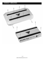
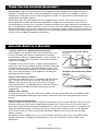
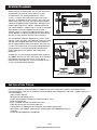
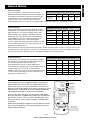
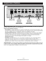
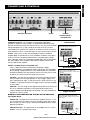
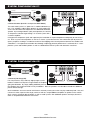
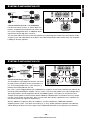
English
Deutsch
Français
Italiano
Español
Português
Svensk
Nederlands
www.midwestelectronics.com
BLAUPUNKT SPECIFICATIONS - VA4100, 4/3/2 CHANNEL AMPLIFIER
All power ratings conform to CEA-2006 standards.
PARAMETER/FEATURE
VA4100
Channels
4/3/2
Size ( L x W x D) without trim panels
15.1x9.1x2.4 inches (382x231x60mm)
Weight
14.5 lbs. (6.6 kg)
Spade screw speaker terminals?
YES
Maximum terminal wire size
10 ga.
Subsonic filter
YES (10 Hz)
Separate front/rear or left/right gains?
F/R-YES
Fuse Type
ATC spade -Two 40A
L/R-NO
Speaker short, short to +12V, and short to ground protection?
YES
High, low, and reverse voltage protection?
YES
Power output transistors
Low QZ MOSFET
Power supply transistors
Minimum speaker impedance
MOSFET
(non-bridged)
2 ohms
(bridged)
4 ohms
PERFORMANCE DATA
Rated power output @ 0.1% THD, 14.4V (CEA-2006)
4 channels into 4 ohms / 2 ohms
(watts rms)
4 x 100 W / 4 x 150 W
2 channels into 4 ohms
(watts rms)
2 x 300 W
Max Dynamic Power (watts rms)
700W
Total Harmonic Distortion @ full power
0.1% THD
Signal/Noise ratio (gain controls in center)
Measured @ 1 watt / 1 kHz
dBA
>80
Measured @ full rated power (0.1% THD)
dBA
>100
Damping factor
>100
Frequency response (full-range mode)
15 - 50,000 Hz
High-pass crossover frequency limits
50 H z - 250 Hz (variable), 12dB/oct
Low-pass crossover frequency limits
50 H z - 250 Hz (variable), 12dB/oct
Input impedance
10 kohms
Input signal voltage control range
0.3 - 6.0 vrms
Current Draw @ 13.8 VDC (typical values @ X watts / Efficiency %)
@ full rated power, unbridged
(@ 4 ohms)
50 A (50%)
@ 33% rated power, unbridged
(@ 4 ohms)
30 A (35%)
@ idle
(@ 4 ohms)
Minimum battery voltage to maintain rated power
1A
12.6 VDC
Usable battery voltage
10 - 16 VDC
Trigger line voltage range
10 - 16 VDC
Trigger line current draw
< 20 mA
Turn on delay time
@ 2.0 seconds
Thermal shutoff temperature (average heat-sink temp)
@ 85˚ C (185˚ F)
This information is subject to change without notice! • Änderungen vorbehalten! • Sous réserve de modifications!
Modifiche riservate! • Wijzigingen voorbehouden! • Ändringar förbehålles! • Modificaciones reservadas! • Sob reserva de alterações!
–1–
www.midwestelectronics.com
ASSEMBLY & MOUNTING
–2–
www.midwestelectronics.com
THANK YOU FOR CHOOSING BLAUPUNKT!
Congratulations! You are the now the owner of an exceptional car audio amplifier from the audio enthusiasts at
Blaupunkt. Our engineering staff has spent considerable time refining our Velocity series amplifiers in order to
introduce great sound to the consumer. With these products we focus on sonic performance but balanced with
rugged design and flexible installation.
Not only do we offer you a great product but also a supportive owners manual. This manual can be used as a
teaching guide due to its brief, but informative, explanations of amplifier and system design. We are also very
concerned about the end consumer using proper installation techniques for the highest performance possible from
their new audio products. MOST important to us are the concerns with safety and the installation process. Since our
Blaupunkt retail dealers have the tools and experience for an optimized and safe installation, we always recommend
they do the final vehicle integration. But, should you choose to install these products yourself, please take the time to
read this manual completely and abide by all precautions.
AMPLIFIER BENEFITS & FEATURES
“THERMAL-THROTTLE” TEMPERATURE PROTECTION
Unlike “dragster” style amplifiers that put out lots of power for a few
minutes, our Velocity series amps are engineered for full throttle,
everyday driving. With our incredible Blaupunkt “Thermal Throttle”, our
amps keep on playing without overheating, the common shut-down
mode for most amplifiers.
All amplifiers heat up some over time. Using our moving voltage rail
design, once warm, the rails pull back to prevent long term overheating
thus preventing full shut off or even possible damage, as most other
amps do. Once initiated this temporary system gain pullback lets you
know you are really pushing the system hard but it’s not letting you
down going into full shut down.
UNIQUE INSTALLATION FLEXIBILITY
Included in your amplifier kit is the very cool looking side rails and end
caps. The side rail system allows you to butt amps side-by-side
building a multi-channel monster of a system but with everything
trimming out beautifully. An added benefit of the side rails and caps is
the dressing down and hiding of all cables preventing any kind of
snagged wires.
Conventional Amplifier Output
Audio Output
Temperature
Thermal Shut-Down
Thermal Shut-Down
Time
Blaupunkt ThermalThrottle™ Output
Audio Output
Temperature
Time
REMOTE GAIN CONTROL
You will find a very nice remote gain control for the amplifier. This gain control works only in the subwoofer mode
(low-pass) providing about 20dB of gain range to dial in accurate bass levels or to simply pound out the tunes if
desired.
NOISE ISOLATION MODE CONTROL
Inside the amplifier are isolation circuits to help prevent the intrusion of noise into the audio path. These circuits are
turned on or off via the small switches visible through the bottom plate. Noise currents may enter the system via
signal cables should there be small ground voltage differences. These are sometimes heard as a varying pitch with
engine speed (alternator whine). The vehicle may also have a poor antenna ground, or overly sensitive AM radio
tuner front end, which can result in low level back ground tones (birdies) in some parts of the AM radio band
(550kHz-1710kHz).
Should either of these conditions occur, use a small screwdriver to slide the switch to the “ON” position and they
should be eliminated. If no problems are detected, leave in the “OFF” position for maximum audio system
performance.
–3–
www.midwestelectronics.com
SAFETY CONCERNS
INSTALLATION WARNINGS!
Before disassembling your beautiful new car you need some basic installation knowledge and skill with
common hand and power tools. Following such basic installation tips and warnings will prevent possible
damage to the vehicle and also prevent possible fires.
• AGAIN...READ THE MANUAL! There is a lot of helpful information in this manual that
will save time and prevent problems later.
• COVER THE VEHICLE WORK AREAS - Use fender covers or blankets to protect the
work areas from scratches or dings.
• DISCONNECT THE (-) LEAD ON THE BATTERY - No sparks or fires please!
• “REVIEW” THE INSTALLATION - Before using any tools or moving vehicle
components, take five minutes to review the installation intentions (e.g., verify that an
amplifier will fit in an area of a car before tearing out all the interior).
• “REVIEW” THE VEHICLE - Before drilling any holes or cutting into any surfaces, make
sure there are no fuel or hydraulic lines behind the surfaces. Also make sure there are
no wires routed directly behind or near the desired mounting area (remember...screws
can often extend 1-2 inches behind the mounting surface).
• ENSURE PROPER FIT - Before cutting or drilling, make sure the amplifier will physically
fit in its desired location. Check for clearance around rear deck torsion bars or other
structural elements.
• EVERY CAR IS ASSEMBLED DIFFERENT - Every auto manufacturer uses different
assembly techniques. Take care in removing/modifying all trim panels and mounting
surfaces since they often use unique screws or snap fasteners that are difficult to replace if they are lost or
broken.
• BE CAREFUL WITH CABLE ROUTING - When routing audio cables, make sure RCA and speaker wires are
routed away from high current power lines for audio amplifiers and vehicle systems lines when possible.
This will help prevent noises from creeping into the audio system, plus prevent potential damage to the
vehicle wiring itself.
• BE CAREFUL WITH ALL CONNECTIONS - When making connections, make sure each connection is clean
and properly secured. Observe all polarity markings carefully to ensure proper end performance.
• CAUTION - FUEL TANKS AND FUEL LINES ARE NOW LOCATED DIRECTLY BENEATH THE REAR DECK
IN MANY CARS - CHECK FOR ADEQUATE CLEARANCE BEFORE EVEN CONSIDERING SUCH A
MOUNTING LOCATION!
–4–
www.midwestelectronics.com
English
We always recommend you have your Blaupunkt amplifiers professionally installed
but the installation process is often so easy that the average consumer can
achieve success with little trouble. Regardless of the person installing, you should
be sure to review the following points before proceeding with the installation:
• READ THE MANUAL! Understanding the product and installation limitations
before lifting a screwdriver.
• WEAR SAFETY GLASSES AT ALL TIMES - Flying debris are always dangerous.
• PROTECT THE VEHICLE - Always disconnect the negative battery cable before
starting any kind of installation work. This prevents a possible high current
electrical short (potential fires).
• HEAT - Keep all audio components away from nearby hot vehicle components that heat up over time such
as hoses, high current wires, and braking system components.
• GIVE YOURSELF LOTS OF TIME - Rushing to complete an installation nearly always ends up with
problems.
• DO NOT LISTEN AT HIGH SOUND LEVELS FOR A PROLONGED TIME - these amplifiers, used with high
efficiency speakers from ANY manufacturer, have the potential to cause permanent hearing loss after
listening at maximum volume levels for several hours.
SYSTEM PLANNING
Before wiring up an audio system that may not achieve the
sound quality you want, be sure to choose a system
concept that fits your listening requirements. Basic
systems, a receiver with internal 4x20 watts and 4 coax
speakers, are adequate for many listeners. But, when you
want to really “feel” the music, you will need some kind of
subwoofer amplifier/speaker combination. Although many
people might jump into an “add-on” amplifier to power to
rear coaxial speakers, a better choice is usually a subwoofer
amp/speaker system that supplements the existing 4
speaker system as shown in the adjacent drawing. Such a
system provides a surprising improvement in sound quality
due to the usually dramatic increase in bass response.
Full-Range
Full-Range
Subwoofer
Full-Range
Full-Range
Supplementary subwoofer system
The next dramatic step up in performance is with a “multichannel” system that offers more dynamic range in the mids
and highs due to higher power plus more bass response
due to multiple woofers and/or more power. But, with such
a system, the stereo image and overall listening experience
usually becomes much more life-like due to better tonal
quality midrange/tweeter speakers and usually better
placement.
Receiver
Sat Amplifier
(4x100 W)
To build such a system though, complexity goes up due to
the addition of passive or active crossovers which take time
to install and may inject noise into the system due to
potential noise signal pick up. The results though of such a
system can be dramatically pleasing.
Passive X-over
Sub Amplifier (2x100 W)
Subwoofers
High performance multi-channel system
INSTALLATION TOOLS
For most installations, simple hand tools are adequate to install an aftermarket amplifier. Depending upon the
mounting locations used, you will need power tools for drilling and cutting plastics and metal. A good starting list is
summarized below:
• Tape measure and ruler
• Marking pen and starting punch
• Phillips and flat blade screwdrivers (small and medium sizes)
• Nylon wire bundle ties
• Pliers: standard vice-grip and needle nose styles
• Light-duty trim pry-bar for removing door trim
• Cutting shears or nibbling tool for cutting thin and medium gauger metal
• Wire cutters, wire strippers, electrical tape, crimping pliers and appropriate crimp-on
terminals
• Power drill with appropriate sized drill bits
–5–
www.midwestelectronics.com
VEHICLE WIRING
POWER WIRING
Most vehicles built since 1990 have adequate current
capability for your amplifier. Except for systems above
about 500 W rms, the factory charging system and
battery should easily support it if properly installed.
Proper wire size must be chosen to ensure adequate
current delivery to the amp. Wire size (gauge) of the
cables need to increase in size for higher power
systems. (Wire sizes larger than those noted are usually
a waste of time and money since they offer Little or no
performance improvements.)
SYSTEM POWER AND GROUND WIRE CHART
(Wire gauge for total system in 'rms' watts)
WIRE LENGTH
100 W
200 W
500 W
5 ft. / 1.5 m
12
10
8
1000 W
4
10 ft. / 3.0 m
12
10
8
4
15 ft. / 4.5 m
10
8
6
2
20 ft. / 6.0 m
10
8
6
2
25 ft. / 7.5 m
10
8
4
0 or 00
Wire diameter must increase (decreased wire gauge number) for higher power systems. For long wire runs the
wire diameter must also increase. The wire sizes noted allow for a maximum 0.5 volts DC drop over the give
wire run which results in Sound Pressure Level drops inaudible to the average listener.
SPEAKER WIRING
As with power wire, speaker wire size (gauge) changes
with the power required and the length of the wire run.
The speaker wire chart shows the minimum
recommended wire size for a single audio output
channel driving a loudspeaker at a given distance with a
maximum power loss of 0.5 dB, the threshold of
audibility. (Wire sizes larger than those noted are usually
a waste of time and money since they offer little or no
performance improvements.)
LOUDSPEAKER WIRE CHART
(Wire gauge per loudspeaker/speaker power in “rms” watts)
WIRE LENGTH
20 W
50 W
100 W
5 ft. / 1.5 m
18
16
16
16
10 ft. / 3.0 m
18
16
16
16
15 ft. / 4.5 m
16
16
16
14
20 ft. / 6.0 m
16
16
16
14
25 ft. / 7.5 m
16
16
14
12
FINAL VEHICLE WIRING
Current requirements for an upgraded audio system dictate a
dedicated power line be run from the amplifier directly to the
battery of the vehicle. This line should NOT be run to the fuse
panel of the vehicle but directly to the battery. DO NOT run to the
alternator either. There MUST be a fuse installed at the battery
with adequate amperage as shown in the chart above.
As for the final signal wiring, be sure to route the audio cables
down the side of the car opposite the power lines to avoid noise
pick up from the lines. Also, try to route all audio cables away
from noise sources such as engine computers and ABS brake
computers.
200 W
Battery
Battery
Connector
Fuse or
Circuit
Breaker
Power Antenna
Turn-On Wire
(18-20 gauge wire)
Grommet
To prevent
damage to
power wire
Power Wire
(10 gauge
wire or larger)
Speaker Wires
or
RCA Cables
Speakers
Proper power grounding is important to insure adequate current
flow. Be sure to grind the surface clean of all paint to ensure a
solid electrical connection.
Amplifier
–6–
www.midwestelectronics.com
Ground Screw
Drill 1/8" hole in
chassis sheet metal
Use the same ground if
using multiple amplifiers
English
VEHICLE FUSING
SYSTEM FUSE CHART
(Fuse size for total amplifier system power in “rms” watts)
For safety purposes, a high current fuse (or circuit
breaker) MUST be installed in line with the amplifiers(s)
100 W
200 W
500 W
1000 W
immediately at the battery to prevent vehicle damage
Fuse Size
20 A
30 A
50 A
100 A
should the battery line in advertently shorted to the
(in amps)
vehicle chassis. The chart at the right shows the
recommended master fuse sizes for an average audio system with noted “rms” output power levels.
CONNECTIONS & CONTROLS
REMOTE GAIN
CONTROL JACK
REAR
CROSSOVER
SELECTOR,
CROSSOVER
MODE SELECTOR
& GAIN CONTROL
FRONT
CROSSOVER
SELECTOR,
CROSSOVER
MODE SELECTOR
& GAIN CONTROL
LINE LEVEL
INPUTS
REMOTE GAIN CONTROL JACK - For connecting the remote gain control (included). This allows you to adjust the
gain while seated in the vehicle with the system operating.
FRONT & REAR CHANNEL CONTROLS
GAIN CONTROL - The gain control allows for a range of 0.3-6Volts input. This means that if the setting is a 0.3V,
it only takes 0.3Volts to drive the amp to full output. (Such a low setting allows for the amp to be easily overdriven
and more susceptible to noise so a mid-position is highly recommended for most radios.)
CROSSOVER MODE SELECTOR - Depending upon the system design chosen, you need to set the amplifier in
the proper “mode”; LP, Flat, or HP. The low-pass and high-pass frequency settings are explained below. The
“Flat” setting simply allows for the amp to pass all audio frequencies without any kind of crossover filter
application. (This is common with 6x9” fullrange coaxial speakers for example.)
CROSSOVER CONTROL
HIGH-PASS - If the Mode Selector is in the “HP” position the amplifier passes only mid and high frequency
sound. The lower limit for such sound is set via this control. A common setting is just above 100Hz.
LOW-PASS - If the Mode Selector is in the “LP” position the amplifier passes only low frequency sound. The
upper limit for such sound is set via this control. For bass, a value just below 100Hz is usually best.
LINE LEVEL INPUTS - The most commonly used inputs in the aftermarket are RCA type line level inputs. These can
handle up to about 6 Volts rms without overdriving the amplifier. Such high voltages are rarely found from car audio
head units so this is a very comfortable value. But, should the use need to drive the amp directly from speaker level
leads, use the supplied “High Level Adapter” to connect to the amp.
–7–
www.midwestelectronics.com
CONNECTIONS & CONTROLS
English
SPEAKER OUTPUTS
FUSES
SPEAKER OUTPUTS - The amplifier is connected to appropriate
impedance speakers via these leads. It is IMPERATIVE that these leads
NOT be connected or touch the vehicle chassis in any way or the amplifier
will be damaged. The (+) and (-) leads of the amp are in no way interconnected to one another. Also, NONE of the leads can touch each other,
touch ground, or touch +12V or damage may occur to the amp or vehicle.
FUSES - These fuses are only for catastrophic situations should the
amplifier begin to self-destruct or incur installation situations where gross
amounts of current are being required from the amp beyond its design
limits. Although another fuse should be installed inline with the high power
line at the battery, these amplifier mounted fuses MUST remain in the
circuit to protect the amplifier.
POWER CONNECTIONS & TRIGGER LINE
+12v - A high current line run direct from the batter is highly
recommended to insure adequate current and voltage. This line MUST
be run through a dedicated fuse of some kind and this fuse should be
located immediately next to the power source. This in-line fuse is used
to protect the vehicle should a short to chassis occur.
POWER
CONNECTIONS &
TRIGGER LINE
+12V Terminal
Connect directly to the vehicle battery (+)
terminal with 10 gage wire (minimum)
NOT SUPPLIED
To Battery
Terminal
Battery
Terminal
Adapter
Ground Terminal
Connect to a good chassis ground. The
ground connection should be clean,
unpainted metal to provide a good electrical
connection.
TRIGGER - This line tells the amp to turn on and is remotely switched
from the radio which normally provides an amp “trigger” output. This
line is required to go “high” (+12V) to turn on the amp. If this line is not
available, use the power antenna line trigger which is normally available
in most radios.
GROUND - This is the high current ground connection to the chassis of
the car. It should be fastened to a clean ground connection in the
vehicle, capable of handling high current loads. This wire should be no
longer than 3 feet (1 meter).
BLUE DOT LIGHT INDICATOR ON THE TOP OF THE AMPLIFIER
(not shown above)
Fuse or
Circuit Breaker
10 Gage
Wire
Sheet
Metal
Screw
10 Gage
Wire
Ring
Connector
Drill 1/8” hole
in chassis
sheet metal
Trigger Terminal
Connect the radio power antenna lead from
the receiver to the trigger terminal. This
turns the amplifier on whenever the receiver
is turned on.
POWER ON - This light will turn on when the amplifier receives a +12V
turn-on signal from the radio. If the amp is properly wired, but the light
does not turn on, there may be a short circuit condition that the amp is
protecting itself from.
PROTECTION LED - This light flashes if the amplifier senses a severe
problem, such as a speaker short circuit.
18-20 Gage
Wire
–8–
www.midwestelectronics.com
To Receiver
Power
Antenna Lead
Butt
Connector
(not supplied)
SYSTEM CONFIGURATION #1
Full-Range
High-Pass
Full-Range
High-Pass
Subwoofer
5 Channel Combo (2ch HP + 3ch passive Multi-Mode)
The multi-mode system is a “poor-man’s” satellite/subwoofer system. This amplifier is able to drive speakers in stereo mode and
at the same time drive low frequencies to a dedicated subwoofer
speaker. By inserting inductors (coils) and capacitors, the result is
an inexpensive solution to generating a ‘5' channel system with a
4 channel amplifier.
Using passive components (coils and capacitors) the installation is simple and performs adequately for most listeners. Such a system will not perform as well as an “active” system because the slow attenuation (roll-off) of the frequency response resulting in a moderate amount of over-lapping of the sound spectrum between the satellites and
subwoofers. It is important to remember that although surprisingly pleasant performance is achieved, this is a compromise system and will NOT perform as well as a dedicated 5 channel system with electronic crossovers.
SYSTEM CONFIGURATION #2
Full-Range
Full-Range
Full-Range
Full-Range
4 Channel (Full-Range,HP)
For many listeners, they need only slightly higher system
loudness and/or music dynamic range without the amplifier
going into distortion. By simply adding additional power to
the speakers this can be achieved in many installations. BUT, the speakers must be able to handle this additional
power without damage.
Such installations are most common with listeners who only need systems that can play moderately loud. Also, this
consumer is often a person who simply cannot, or will not, accept additional amplifiers or speakers in the vehicle.
Such systems will not be able to perform as well as audio systems with additional speakers and amps, but this is
often an accepted trade-off for this consumers.
–9–
www.midwestelectronics.com
SYSTEM CONFIGURATION #3
English
Full-Range
Full-Range
Full-Range
Subwoofer
Full-Range
3 Channel Combo (2ch HP + 1ch Subwoofer)
Like the four channel systems as shown above, the
benefits, and performance trade-offs are similar. But,
this system configuration offers an additional advantage with the internal high-pass crossover.
This crossover reduces the bass to the front speakers thus protecting them under heavy low frequency loads.
A typical system with larger drivers in the back is then able to be pushed harder without worry over the power
handling on the front speakers.
SYSTEM CONFIGURATION #4
Full-Range
Full-Range
OR
HP
Full-Range
Full-Range
OR
HP
Subwoofer
LP
Subwoofer
LP
OR
2 Channel (Full-Range, HP, LP)
This installation is most popular for listeners who want
to simply increase the power to the rear speakers in a
car. The resulting performance is most commonly a
louder overall sound field from the rear.
But, such a system’s biggest benefit is the additional bass response since the bass control of the radio can be
turned up without distorting the amplifier. Such a system is not necessarily louder in the mids and highs but is
able to play louder in the low frequencies due to this additional power. This leads to an overall richer and
stronger sound experience for the listener without additional subwoofer boxes or electronics that may complicate the system or take up more room. Such a system WILL NOT equal the performance of a subwoofer system but will certainly be a pleasant improvement.
With the addition of a high-pass filter, this amplifier is set up to complement a dedicated subwoofer
amplifier/speaker system. This allows for smaller (e.g., 5" or 6") satellite speakers to operate most efficiently
without being over-driven in the bass region where a dedicated subwoofer system operates most efficiently.
– 10 –
www.midwestelectronics.com
TROUBLE-SHOOTING GUIDE
Below is a basic trouble-shooting guide to assist in seeking out and correcting a problem that may occur in the
installation process. Although lengthy, this chart cannot address every single problem possible but mainly the ones
most common.
SYMPTOM
PROBABLE CAUSE OR CORRECTION
No power (power light not on)
•
•
•
•
•
Power but no sound (power light is on)
• Check all input cable lines for connection.
• Disconnect speakers from amp, test speaker lines with digital voltmeter to verify >2 ohms per
channel (non-bridged mode).
No sound from one channel or entire side
• Check radio’s balance and fader control positions - verify they are at center.
• Check speaker connections at amp and speaker.
• Check input leads for connection to amp.
Very low sound level
• Verify radio balance and fader controls are at center positions.
• Check amplifier’s input gain control setting - adjust for higher output levels if necessary (gain
settings closer to 0.3 volts).
• Receiver may have very low output voltage levels - a step up “line driver” may have to be
used.
Power amplifier turns on and off repeatedly
(motor-boating sound)
• Make sure power connections at batter are tight.
• Verify battery voltage is >11.5 volts DC (12.5-15V engine on) at amplifier with engine off.
• Check all radio and amplifier ground connections.
Amplifier turns off during loud or distorted
passages
•
•
•
•
Amplifier performs fine but gets very hot to
the touch
• Input gain control too high - lower accordingly (closer to 4.0 volt setting).
• Verify speaker loads >2 ohms on all channels (non-bridged mode).
• Verify the mounting location allows for free air movement around the amp. Preferably, the amp
should be mounted with fins up and down so rising heat moves quickly away from amp.
Amplifier turn-on/turn-off pops or noises
• “turn on race” - disconnect trigger from radio and turn on/off via a wire jumper to power
terminal. If noise goes away, the radio is turning on/off too slowly. This is radio problem and
can only be corrected with outboard turn-on delay relay system.
• Radio “thump” - disconnect the RCA input lines to the amp and turn on/off via radio trigger. If
noise goes away without RCA lines connected, the radio is sending pops out through RCA
lines. This is a radio problem and can only be corrected with outboard turn-on delay relay
system.
Cracking noises on AM/FM radio but not on
tape or cd.
• Ensure the problem is “radiated noise” by placing a portable FM radio near the car engine. If
noise is picked up, then it is a vehicle problem and not your system. Research to isolate the
source and properly shield or bypass.
• Are spark plugs and wires > 3 years old? These can often radiate substantial noise when old.
• Verify the engine block has a good ground connection to chassis ground.
• Verify the engine compartment hood is grounded to vehicle chassis via a braided grounding
strap.
Whining noise, engine running, varies in pitch
or loudness with engine speed, AND varies
with radio volume control setting (this is
generally a RADIO installation problem)
• Verify all power and ground connections are clean at radio.
• Re-route radio power and ground so they are sourced from same connections back at
amplifier (this is called a “common” ground).
• Check all ground connections to ensure clean surfaces that have all paint removed and also
not oxidation buildup over time.
• Verify there is some kind of power filtering choke assembly at back of radio. If not, install one.
Whining noise, engine running, varies in pitch
or loudness with engine speed, BUT, DOES
NOT vary with radio volume control setting
(this is generally an amplifier installation
problem)
• Check battery ground connections at chassis are clean and tight, scraped free of oxidation,
paint, and grease.
• Re-route radio power and ground so they are sourced from same connections back at
amplifier (this is called a “common” ground).
• Bypass all equipment between radio and amp (e.g., equalizers) directly connecting radio. If
noise goes away, signal processor has problem.
• Check for signal level “ground loops” - disconnect the outer shield of the RCA cable at one
end of the cable (e.g., radio end). If noise goes away, modify cables accordingly. There are
voltage differences at the ground connections of the components and these are NOT
correctable any other way than such shield cutting or an outboard “ground loop isolator”
which is a small transformer.
Check connections to amps +12 volt, ground, and remote lines.
Use voltmeter to verify voltages are at terminals of amp.
Check main power connection at battery.
Check fuse in power line at battery.
Disconnect all speakers but not power lines - if unit then turns on, a speaker short or speaker
line touching vehicle chassis is likely.
Input stage being over-driven - lower input gain (closer to 4 volt setting).
Verify battery voltage is >11.5 volts DC at amplifier with engine off.
Check all radio and amplifier ground connections.
Verify speaker loads >2 ohms on all channels (non-bridged mode).
– 11 –
www.midwestelectronics.com
GUARANTEE (EUROPEAN UNION)
Blaupunkt GmbH
Hotline
Robert Bosch Str. 200
D-31139 Hildesheim
Germany
LIMITED WARRANTY (UNITED STATES ONLY)
Robert Bosch Corporation (for products sold in the United States) warrants new Blaupunkt car audio products distributed in the
United States through authorized Blaupunkt dealers, or which are imported as original vehicle equipment by the automobile
manufacturer, to be free from defects in material and workmanship, in accordance with the following terms and conditions:
For twelve (12) months after delivery to you, the original consumer purchaser, we will repair or at our option replace at no charge
to you any car audio product which, under normal conditions of use and service, proves to be defective in materials or
workmanship. However, this warranty does not cover expenses incurred in the removal or reinstallation of any car audio
product, whether or not proven defective, and does not cover products not purchased from an authorized Blaupunkt dealer.
This warranty is limited to the original consumer purchaser and is not transferable. Repaired and replacement car audio
products shall assume the identity of the original for purpose of this warranty and this warranty shall not be extended with
respect to such products.
To obtain performance of this warranty, contact the nearest Blaupunkt authorized repair facility or our nearest office. A dated
purchase receipt or other proof that the product is within the warranty period will be required in order to honor your claim.
Carefully pack the unit and ship prepaid to the servicing location.
For further information: In the United States, write to the Robert Bosch Corporation, 2800 South 25th Avenue, Broadview,
Illinois, 60155, attention Blaupunkt Customer Service Department or call 1-800-950-2528.
Specifically excluded from this warranty are failures caused by misuse, neglect, abuse, improper operation or installation,
dropping or damaging a radio faceplate, unauthorized service or parts, or failure to follow maintenance instructions or perform
normal maintenance activities. Normal maintenance activities for car audio products include but are not limited to cleaning, such
as cleaning radio faceplate connectors and tape heads, tape player head demagnetization and tape player lubrication, compact
disc and lens cleaning, and other minor maintenance activities and adjustments that are outlined in the owner’s manual or that
are normally required for continued proper operation. Also excluded from this warranty are the correction of improper installation
and the elimination of any external electromagnetic interference.
THIS WARRANTY SETS FORTH YOUR EXCLUSIVE REMEDIES WITH RESPECT TO THE PRODUCTS COVERED BY IT. WE
SHALL NOT BE LIABLE FOR ANY INCIDENTAL, CONSEQUENTIAL, SPECIAL OR PUNITIVE DAMAGES ARISING FROM THE
SALE OR USE OF ANY BLAUPUNKT CAR AUDIO PRODUCTS, WHETHER SUCH CLAIM IS IN CONTRACT OR TORT. NO
ATTEMPT TO ALTER, MODIFY, OR AMEND THIS WARRANTY SHALL BE EFFECTIVE UNLESS AUTHORIZED IN WRITING BY
AN OFFICER OF ROBERT BOSCH CORPORATION.
THIS WARRANTY IS IN LIEU OF ALL OTHER WARRANTIES OR REPRESENTATIONS, EXPRESS OR IMPLIED, INCLUDING
ANY WARRANTY IMPLIED BY LAW, WHETHER FOR MERCHANTABILITY OR FITNESS FOR A PARTICULAR PURPOSE OR
OTHERWISE AND SHALL BE EFFECTIVE ONLY FOR THE PERIOD THAT THIS EXPRESS WARRANTY IS EFFECTIVE.
ANY IMPLIED WARRANTY SHALL BE LIMITED IN DURATION TO ONE YEAR FROM DATE OF PURCHASE. SOME STATES IN
THE U.S. DO NOT ALLOW LIMITATIONS ON HOW LONG IMPLIED WARRANTY LASTS. SO THE ABOVE LIMITATIONS MAY
NOT APPLY TO YOU.
THIS LIMITED WARRANTY GIVES YOU SPECIFIC LEGAL RIGHTS, AND YOU MAY ALSO HAVE OTHER RIGHTS WHICH VARY
FROM STATE TO STATE IN THE U.S.
In the event any provision, or any part or portions of this warranty shall be held invalid, void or otherwise unenforceable, such
holding shall not affect the remaining part or portions of that provision or any other provision hereof.
ROBERT BOSCH CORPORATION
BLAUPUNKT CUSTOMER SERVICE
2800 SOUTH 25TH AVENUE
BROADVIEW, IL 60155
TEL: 1-800-950-2528
BLAUPUNKT TECHNICAL SUPPORT
Blaupunkt is constantly working on making the operating instructions clearer and easier to understand. However,
if you still have questions on how to operate the amplifier, please contact your dealer or the telephone hotline for
your country. You will find the hotline telephone numbers printed at the back of this booklet.
– 12 –
www.midwestelectronics.com
English
We provide a manufacturer guarantee for our products bought within the European Union. You can view the
guarantee conditions at www.blaupunkt.de or ask for them directly at:
SERVICE NUMBERS • SERVICE-NUMMERN • NUMÉROS DU SERVICE APRÈS-VENTE
NUMERI DEL SERVIZIO DI ASSISTENZA • NÚMEROS DE SERVICIO
NÚMERO DE SERVIÇO • SERVICENUMMERS • TELEFONNUMMER FÖR SERVICE
Country:
Phone:
Fax:
WWW:
Germany
(D)
0180-5000225
05121-49 4002
http://www.blaupunkt.com
Austria
(A)
01-610 3150
01-610 393 91
Belgium
(B)
02-525 51004
02-525 5263
Denmark
(DK)
44 898 360
44-898 644
Finland
(FIN)
09-435 991
09-435 99236
France
(F)
01-4010 10007
01-4010 7320
Great Britain
(GB)
01-89583 8880
01-89583 8394
Greece
(GR)
0800-550 6550
01-576 9473
Ireland
(IRL)
01-4149400
01-10098830
Italy
(I)
02-369 6331
02-369 6464
Luxembourg
(L)
40 4078
40 2085
Netherland
(NL)
023-565 6348
023-565 6331
Norway
(N)
66-817 000
66-817 157
Portugal
(P)
01-2185 00144
01-2185 11111
Spain
(E)
1502-120234
916-467952
Sweden
(S)
08-7501500
08-7501810
Switzerland
(CH)
01-8471644
01-8471650
Czech. Rep.
(CZ)
02-6130 0441
02-6130 0514
Hungary
(H)
01-333 9575
01-324 8756
Poland
(PL)
0800-118922
022-8771260
Turkey
(TR)
0212-3400677
0212-3460040
USA
(USA)
800-950-2528
708-681-7188
(BR)
+55-19 37100 2769 +55-19 37100 2773
(MAL)
+604-6382 474
http://www.blaupunktusa.com
Brazil
(Mercosur)
Malaysia
(Asia Pacific)
Robert Bosch Corporation
Sales Group - Mobile
Communications Division
2800 S. 25th Avenue
Broadview, IL 60155 U.S.A.
+604-6413
Blaupunkt GmbH
Robert Bosch Strasse 200
D-31139 Hildesheim
Germany
www.blaupunkt.com
www.blaupunktusa.com
Copyright 2005 by the Robert Bosch Corporation
No portion of this work may be reproduced in any form without the written consent of the Robert Bosch Corporation
Printed in China
www.midwestelectronics.com