1
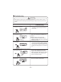
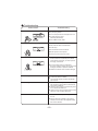
BK 2600
BK 3500
Split Air Conditioner
User Manual
2SHUDWLRQDQGPDLQWHQDQFHQRWLFHVIRURSHUDWLRQ
ƾ (DUWK7KHJURXQG ƾ%HVXUHWRSXOORXWWKHSRZHU ƾ 6HOHFWWKHPRVWDSSURSULDWHWHP
EHFRQQHFWHG SOXJZKHQQRWXVLQJWKHDLUFR
QGLWLRQHUIRUDORQJWLPH
SHUDWXUH
.HHSURRPFRRlHUWKDQRXWVLGH
DERXWGHJUHH
,IQRWSOHDVHDVNWKHTXDOLILHGSHUVRQ
QHOWRLQVWDOO)XUWKHUPRUHGRQ
WFRQQ
HFWHDFKZLUHWRWKHJDVSLSHZDWHU
SLSHGUDLQDJHSLSHRUDQ\RWKHULPSU
RSHUSODFHV
2WKHUZLVHWKHDFFXPXODWHGGXVW
PD\FDXVHILUHRUHOHFWULFVKRFN
ƾ 'RQ
WOHDYHZLQGRZVDQG
ƾ 'RQ
WEORFNWKHDLULQWDNHRURXWOHW
,WFDQGHFUHDVHWKHDLUFRQGLWLRQLQJ
FDSDFLW\
,WFDQGHFUHDVHWKHDLUFRQGLWLRQLQJ
FDSDFLW\RUFDXVHDPDOIXQFWLRQ
GRRUVRSHQIRUDORQJWLPH
ZKLOHRSHUDWLQJWKHDLUFRQGLWLRQHU
ƾ 3OHDVHQRWHZKHWKHUWKHLQVWDOOHG
VWDQGLVILUPHQRXJKRUQRW
,ILWLVGDPDJHGLWPD\OHDGWR
WKHIDOORIWKHXQLWDQGFDXVH
WKHLQMXU\
YHQWVRIERWKWKHRXWGRRUDQGLQGRRU
XQLWV
ƾ
'RQ
WVWHSRQWKHWRSRIWKH
RXWGRRUXQLWRUSODFHVRPHWKLQJ
RQLW
$VIDOOLQJRIIWKHRXWGRRUXQLW
FDQEHGDQJHURXV
1
,WFDQSUHFOXGHWKHHOHFWULFLW\ZDVWHG
ƾ .HHSFRPEXVWLEOHVSUD\DZD\
IURPWKHXQLWVPRUHWKDQP
,WFDQFDXVHDILUHRUH[SORVLRQ
ƾ
'RQ
WDWWHPSWWRUHSDLU
WKHDLUFRQGLWLRQHUE\\RXUVHOI
7KHZURQJUHSDLUZLOOOHDGWR
DQHOHFWULFVKRFNRUILUHVR
\RXVKRXOGFRQWDFWWKHVHUYLFH
FHQWHUWRUHSDLU
Notices for operation
ƾ If the supply cord is damaged, it must be replaced
ƾ 7KHDLUIORZGLUHFWLRQFDQEHDGMXVWHGDSSUR
SULDWHO\$WRSHUDWLQJDGMXVWWKHYHUWLFDODLUIORZ
GLUHFWLRQE\DGMXVWLQJWKHORXYHUVRIXSZDUGGR
ZQZDUGGLUHFWLRQ$QGWKHQKROGWZRHQGVRI
OHIWDQGULJKWORXYHUWRDGMXVWWKHKRUL]RQWDODLU
IORZ
by the manufacturer or its service agent or a
similarly qualified person in order to avoid a
hazard.
/RXYHURIOHIWULJKWGLUHFWLRQ
ƾ
'RQ
WLQVHUW\RXUKDQGVRUVWLFNLQWRWKHDLU
LQWDNHRURXWOHWYHQWV
/RXYHURIXSZDUG
GRZQZDUGGLUHFWLRQ
ƾ 'RQ
WEORZWKHZLQGWRDQLPDOVDQGSODQWV
GLUHFWO\,WFDQFDXVHDEDGLQIOXHQFHWRWKHP
2WKHUZLVHLWZLOOFDXVHDFFLGHQW
ƾ 'RQ
WDSSO\WKHFROGZLQGWRWKHERG\IRUD
ƾ 'RQ
WXVHWKHDLUFRQGLWLRQHUIRURWKHUSXUSRVHV
VXFKDVGU\LQJFORWKHVSUHVHUYLQJIRRGVHWF
ORQJWLPH
,WFDQFDXVHWKHKHDOWKSUREOHPV
ƾ 6SODVKLQJZDWHURQWKHDLUFRQGLWLRQHUFDQ
ƾ 'RQ
WSODFHDVSDFHKHDWHUQHDUWKHDLU
FDXVHDQHOHFWULFVKRFNDQGPDOIXQFWLRQ
FRQGLWLRQHU
2U&2WR[LFRVLVPD\RFFXUIRULPFRPSOHWH
EXUQLQJ
2
1RWLFHVIRUXVH
:RUNLQJSULQFLSOHDQGVSHFLDOIXQFWLRQVIRUFRROLQJ
3ULQFLSOH
Air conditioner absorbs heat in the room and transmit to outdoor and discharged, so that
indoor ambient temperature decreased, its cooling capacity will increase or decrease by
outdoor ambient temperature.
$QWLIUHH]LQJIXQFWLRQ
If the unit is running in COOL mode and in low termperature, there will be frost formed on
the heat exchanger, when indoor heat exchanger temperature decreased below 0ć , the
indoor unit microcomputer will stop compressor running and protect the unit.
:RUNLQJSULQFLSOHDQGVSHFLDOIXQFWLRQVIRUKHDWLQJ
3ULQFLSOH
Air conditioner absorbs heat from outdoor and transmits to indoor, in this way to increase
room temperature. This is the heat pump heating principle, its heating capacity will be
reduced due to outdoor temperature decrease.
If outdoor temperature becomes very low, please operate with other heating equipments.
'HIURVWLQJ
When outdoor temperature is low but high humidity, after a long while running, frost will
form on outdoor unit, that will effect the heating effect, at this time, the auto defrosting
function will act, the heat running will stop for 8-10mins.
During the auto defrosting, the fan motors of indoor unit and outdoor unit will stop.
During the defrosting, the indoor indicator flashes, the outdoor unit may emit vapor.
This is due to the defrosting, it isn't malfunction.
After defrosting finished,the heating will recover automatically.
The climate type of this unit is according to the nameplate.
The external static pressures at which the appliance was tested should be zero Pa.
3
Notices for use
Anti-cool wind function:
In "Heat" mode, under the following three kinds of state, if indoor heat exchanger doesn't
arrive at certain temp., indoor fan will not act, in order to prevent cool wind blowing(within
2 mins):
1. Heating starts. $IWHU$XWR'HIURVW¿QLVKHG. 3.Heating under the low temperature.
Gentle Breeze
In the following situation, the indoor unit may blow gentle breeze, and
the guide louver rotate to a certain position:
1. In “Heat” mode, the unit turned on, the compressor doesn’t arrive the starting condition.
2. In “Heat” mode, the temperature arrive at the setting value and the compressor stop
running about 1min.
Working temperature range
Indoor sideDB/WB(oC)
Outdoor sideDB/WB(
Maximum cooling
35/24
Minimum cooling
21/15
21/-
Maximum heating
24/---
21/15.5
Minimum heating
20/---
-7/-
43/-
The operating temperature range (outdoor temperature) for cooling unit is 18ć~ 43ć˗
for cooling and heating unit is -7ć~ 43ć.
4
1DPHVDQGIXQFWLRQVRIHDFKSDUW
,QGRRUXQLW
$LULQ
Ł
Ń
ń
Ņ
ņ
$LURXW
7KH SDWWHUQ LQ GLVSOD\HU˖
Ň
ł
˖&RRO
˖'U\
:LUHOHVV
UHPRWHFRQWURO
˖)DQ
Ł 3RZHUFDEOH
˖+HDW
ł 5HPRWHFRQWURO
˖5XQ
Ń )URQWSDQHO
˖6HW WHPS
ń )LOWHU
Ņ *XLGHORXYHU
2XWGRRUXQLW
ņ :DOOSLSH
$LULQ
Ň %LQGWDSH
ň &RQQHFWLRQZLUH
ʼn 'UDLQDJHSLSH
ň
$LURXW
ʼn
Operation of wireless remote control
Names and functions of wireless remote control
Note: Be sure that there are no obstructions between receiver and remote
controller ;
Don't drop or throw the remote control; Don't let any liquid in the remote control and
put the remote control directly under the sunlight or any place where is very hot.
SLEEP
Signal transmitter
SLEEP button
ƽ
FAN
Press this button, Sleep On and Sleep
Off can be selected. After powered on,Sleep
Off is defaulted. After the unit is turned
off, the Sleep function is canceled. After
Sleep function set up, the signal of Sleep
will display. In this mode, the time of timer
can be adjusted. Under Fan and Auto
modes, this function is not available.
FAN button
ƽ Press this button, Auto, Low, Middle, High
speed can be circularly selected. After
powered on,Auto fan speed is default.
Under Dehumidify mode, Low fan speed
only can be set up.
Remote control
Low fan
Middle fan
High fan
ON/OFF
Note:Under the Dry mode, the fan speed isn't
adjustable, low fan speed is imperative,
but when operating this button, the wireless
adjustable, low fan speed is imperative,
ON/OFF button
CLOCK
ƽ Press this button, the unit will be turned on,
press it once more, the unit will be turned
off. When turning on or turning off the unit,
the Timer, Sleep function will be canceled,
but the presetting time is still remained.
MODE
CLOCK button
ƽ Press this button, the clock can be set up,
signal blink and display.Within 5
seconds, the value can be adjusted by
pressing + or - button, if continuously
press this button for 2
seconds above,
in every 0.5 seconds, the value on ten place
of Minute will be increased 1. During blinking,
repress the Clock button,
signal
will be
constantly displayed and
it denotes the
setting succeeded. After
powered on, 12:00
is defaulted to display
and signal
will
be displayed. If there is
signal be
displayed that denotes the current time
value is Clock value, otherwise
is Timer value.
MODE button
ƽ
Press this button, Auto, Cool,Dry, Fan,
Heat mode can be selected circularly.
Auto mode is default while power on.
Under Auto mode,the temperature will not
be displayed; Under Heat mode, the
o
initial value is 28
( 82 F) ;Under other
modes, the initial value is 25
o
( 77 F).
LIGHT
LIGHT button
ƽ
AUTO
COOL
Press this button to select LIGHT on or off
in the displayer. When the LIGHT o
n is
set,the icon will be displayed and the
DRY
indicator light
FAN
When the LIGHT
HEAT
(only for cooling and heating unit)
not be display ed and the indicator light
in the displayer will be on.
off is set, the icon
in the displayer will be off.
6
will
Operation of wireless remote control
Names and functions of wireless remote control
Notice: This is a general use remote controller, it could be used for the air conditioners
with multifunction; For some function, which the model dosen't have, if press the
corresponding button on the remote controller that the unit will keep the original
running status.
+
Remote control
X-FAN
-
For presetting temperature increasing.
Press this button,can set up the temperature,
when unit is on . Continuously
press and
hold this button for more than 2 seconds,
the corresponding contents will be
changed rapidly, until unpress the button
then send the information,
is displaying all along. In Auto mode, the temperature can not be set up, but operate this
button can send the signal. Centigrade
setting range :16-30; Fahrenheit scale
setting range 61-86.
ƽ
In Cool or Heat mode, press this button
can turn on or turn off the Turbo function.
After turned on the Turbo function, its
signal will be displayed. When switching
the mode or changing fan speed, this
function will be canceled automatically.
TURBO
X-FAN button
ƽ
+ button
ƽ
TEMP
PressingX-FAN button in COOL or DRY
mode,the icon is displayed and the
indoor fan will continue operation for
10 minute in order to dry the indoor unit
even though you have turned off the unit.
After energization, X-FAN OFF is defaulted.
X-FAN is not available in AUTO,FAN or
HEAT mode.
Note:X-FAN (or BLOW:same function,
different name)
TURBO button
TEMP button
ƽ Press this button, could select displaying
the indoor setting temperature or indoor
ambient temperature.When the indoor unit
firstly power on it will display the setting
temperature, if the temperature's displaying
status is changed from other status to" ",
displays the ambient temperature, 5s later
or within 5s, it receives other remote control
signal that will return to display the setting
temperature. if the users haven't set up the
temperature displaying status,that will
display the setting temperature.
(This function is applicable to partial of models)
- button
ƽ Presetting temperature can be decreased.
Press this button, the temperature can be
set up, continuously press this button
and hold for two seconds, the relative
contents can quickly change, until unhold
this button and send the order that the
o
( F) signal will be displayed all the time.
The temperature adjustment is unavailable under the Auto mode, but the order
can be sent by if pressing this button.
7
Operation of wireless remote control
Names and functions of wireless remote control
Notice: This is a general use remote controller, it could be used for the air conditioners
with multifunction; For some function, which the model dosen't have, if press the
corresponding button on the remote controller that the unit will keep the original
running status.
TIMER ON
TIMER ON BUTTON
ƽ
Time r On setting : Signa l “ON ” wil l blin k
an d display , signa l
wil l conceal , the
numerica l sectio n wil l becom e the time r
on settin g status . Durin g 5 second s blink ,
by pressin g ˇ or ˉ butto n to adjus t the
tim e valu e of numerica l section , ever y
pres s of tha t button , the valu e wil l be
increase d or decrease d 1 minute . Hol d
pressin g ˇ or ˉbutton , 2 second s later ,
it quickl y change , the wa y of chang e is :
Durin g the initia l 2. 5 seconds , ten number s
chang e in the on e plac e of minute , the n
the on e plac e is constant , ten number s
chang e in the ten s plac e of minut e at 2. 5
second s spee d an d carry . Durin g 5s blink ,
pres s the Time r button , the time r settin g
succeeds . Th e Time r On ha s bee n se t up ,
repres s the time r On button , the Time r
On wil l be canceled . Befor e settin g the
Timer , pleas e adjus t the Cloc k to the
curren t actua l time .
ƽ
Once press this key to enter into
TIMER OFF
setup, in which case
the TIMER OFF
icon will blink.
The method of setting
is the same
Remote control
SWING UP AND DOWN BUTTON
ƽ
TIMER OFF
TIMER OFF BUTTON
Press this button, to set up swing angle,
which circularly changes as below:
OFF
as for TIMER
This is an universal use remote controller. If
remote controller sends the following three
kinds of status that the swing status of main
unit will be:
When the guide louver start to swing up and
down, if turn off the Swing, the air guide louver
will stop at current position.
which indicates the guide louver swings up
and down between that all five positions.
8
ON.
Operation of wireless remote control
Guide for operation- General operation
1. After powered on, press ON/OFF button, the unit will start to run.(Note: When
it is powered off, the guide louver of main unit will close automatically.)
2. Press MODE button, select desired running mode.
3. Pressing +or - button, to set the desired temperature. (It is unnecessary
to set the temp. at AUTO mode.)
4. Pressing FAN button, set fan speed, can select AUTO FAN, LOW, MID
and HIGH.
5. Pressing
button, to select the swing.
Guide for operation- Optional operation
1. Press SLEEP button, to set sleep.
2. Press TIMER ON and TIMER OFF button, can set the scheduled timer on
or timer off.
3. Press LIGHT button, to control the on and off of the displaying part of the
unit (This function may be not available for some units).
4. Press TURBO button, can realize the ON and OFF of TURBO function.
Introduction for special function
About X-FAN function
This function indicates that moisture on evaporator of indoor unit will be blowed after the unit
is stopped to avoid mould.
1. Having set X-FAN function on: After turning off the unit by pressing ON/OFF button
indoor fan will continue running for about 10 min. at low speed. In this period, press
X-FAN to stop indoor fan directly.
2. Having set X-FAN function off: After turning off the unit by pressing ON/OFF button, the
button complete unit will be off directly.
About AUTO RUN
When AUTO RUN mode is selected, the setting temperature will not be displayed on the
LCD, the unit will be in accordance with the room temp. automatically to select the suitable
running method and to make ambient comfortable.
About turbo function
If start this function, the unit will run at super-high fan speed to cool or heat quickly so that
the ambient temp. approachs the preset temp. as soon as possible.
9
Operation of wireless remote control
ƾ About lock
Press +and - buttons simultaneously to lock or unlock the keyboard. If the remote controller
will be displayed on it, in which case, press any button, the mark will
is locked, the icon
flicker for three times. If the keyboard is unlocked, the mark will disappear.
ƾ About swing up and down
1. Press swing up and down button continuously more than 2s,the main unit will swing back
and forth from up to down, and then loosen the button, the unit will stop swinging and present
position of guide louver will be kept immediately.
2. Under swing up and down mode, when the status is switched from off to , if press this
button again 2s later,
status will switch to off status directly; if press this button again
within 2s,the change of swing status will also depend on the circulation sequence stated above.
ƾ About switch between Fahrenheit and Centigrade
Under status of unit off, press MODE and - buttons simultaneously to switch ćanḑ
Changing batteries and notices
Slightly to press the place with
, along the arrowhead direction to push the back cover of wireless
remote control. (As show in figure)
Take out the old batteries. (As show in figure)
Insert two new AAA1.5V dry batteries, and pay attention to the polarity.
(As show in figure)
Attach the back cover of wireless remote control. (As show in figure)
ƾ NOTE:
ƽ When changing the batteries, do not use the old or different batteries,
otherwise, it can cause the malfunction of the wireless remote control.
ƽ If the wireless remote control will not be used for a long time, please
take them out, and don't let the leakage liquid damage the wireless
remote control.
ƽ The operation should be in its receiving range.
ƽ It should be placed at where is 1m away from the TV set or stereo sound sets.
ƽ If the wireless remote control can not operate normally, please take them out,
after 30s later and reinsert, if they cannot normally run, please change them.
10
Sketch map for
changing batteries
Emergency operation
Displayer indicator light control of indoor unit
It's a special selective buttonfor the users ,who are not accustomed to the
light at sleeping.
ƽ Get
the displayer indicator light on: When setting the light function,the mark will
display on the remote controller screen by
pressing this button. In which case,the dissplayer indicator light will be on if the AC receives
this signal.
ƽ Get
the displayer indicator light off: If cancel the light function,the mark
will disap-
per on the remote controller screen by pressing this
button. In which case, the displayer indicator light will
be off if the AC receives this signal.
Emergency operation
If the wireless remote control is lost
or broken, please use the manual switch
button. At this time, the unit will run at the
Auto mode, but the temperature and fan
speed cannot be changed. The operation
was shown as below:
Manual switch
To open the panel, the manual switch
is on the displayer box.
ƽ
Turn on the unit: At unit turned off, press
the button,the unit will run at Auto mode
immediately.The microcomputer will accord
to the indoor temperature to select (Cooling,
Heating, Fan) and obtain the comfortable effect.
ƽ
Turn off the unit: At unit turned on, press the
button, the unit will stop working.
11
Fig.3
Clean and care
&DXWLRQ
ƽ
ƽ
ƽ
7XUQSRZHURIIDQGSXOORXWWKHSRZHUSOXJEHIRUHFOHDQLQJDLUFRQGLWLRQHURULWPD\FDXVH electric
VKRFN
1HYHUVSULQNOHZDWHURQWKHLQGRRUXQLWDQGWKHRXWGRRUXQLWIRUFOHDQLQJEHFDXVHLWFDQFDXVH an
HOHFWULFVKRFN
9RODWLOHOLTXLGHJWKLQQHURUJDVROLQHZLOOGDPDJHWKHDLUFRQGLWLRQHU6RZLSHWKHXQLWVZLWKD
GU\VRIWFORWKRUDFORWKVOLJKWO\PRLVWHQHGZLWKZDWHURUFOHDQVHU
&OHDQWKHIURQWSDQHO
:KHQFOHDQLQJWKHIURQWSDQHOSOHDVHGLSWKHFORWKLQWRWKHZDWHUWHPSHUDWXUHRIEHORZthen
to dry
ć
WKHFORWKDQGZLSHWKHGLUW\SDUW
1RWH3OHDVHGRQRWWRLPPHUVHWKHIURQWSDQHOLQZDWHUGXHWRWKHUHDUHPLFURFRPSXWHUFRPSRQHQWV and
FLUFXLWGLDJUDPVRQWKHIURQWSDQHO
&OHDQWKHDLUILOWHU5HFRPPHQGHGRQFHHYHU\WKUHHPRQWKV
127(,IGXVWLVPXFKPRUHDURXQGWKHDLUFRQGLWLRQHUWKHDLUILOWHUVVKRXOGEHFOHDQHGPDQ\WLPHV
$IWHUWDNLQJRIIWKHILOWHUGRQ
WWRXFKWKHILQRILQGRRUXQLWLQRUGHUWRDYRLGKXUW\RXUILQJHUV
ķ 7DNHGRZQWKHDLUILOWHU
$WWKHVORWRIVXUIDFHSDQHOWRRSHQDQDQJOHSXOOWKHDLUILOWHU
GRZQZDUGDQGWDNHLWRXWSOHDVHVHHWKH)LJDE
D
E
ĸ CleanWKHDLUILOWHU
)LJ
7RFOHDQWKHGXVWDGKHULQJWRWKHILOWHUV\RXFDQHLWKHU
XVHDYDFXXPFOHDQHURUZDVKWKHPZLWKZDUPZDWHU
WKHZDWHUZLWKWKHQHXWUDOGHWHUJHQWVKRXOGEHORZ
GHJUHHDQGGU\LWLQWKHVKDGH
127(1HYHUXVHZDWHUDERYHWRFOHDQRULWFDQ
ć
FDXVHGHIRUPDWLRQRUGLVFRORUDWLRQ1HYHUSDUFKLWE\
ILUHRUFDQFDXVHDILUHRUGHIRUPDWLRQ
Ĺ ,QVHUWWKHDLUILOWHU
5HLQVHUWWKHILOWHUVDORQJWKHGLUHFWLRQRIDUURZKHDGDQG
WKHQWRFRYHUWKHFRYHUDQGFODVSLW
12
Clean and care
&KHFNEHIRUHXVH
ķ%HVXUHWKDWQRWKLQJREVWUXFWVWKHDLURXWOHWDQGLQWDNHYHQWV
ĸ&KHFNWKDWZKHWKHUJURXQGZLUHLVSURSHUO\FRQQHFWHGRUQRW
Ĺ&KHFNWKDWZKHWKHUWKHbatteriesRIDLUFRQGLWLRQHUDUH
FKDQJHGRUQRW
ĺ&KHFNWKDWZKHWKHUWKHLQVWDOODWLRQVWDQGRIWKHRXWGRRU
XQLWLVGDPDJHGRUQRW,IGDPDJHGSOHDVHFRQWDFWWKHGHDOHU
0DLQWDLQDIWHUXVH
ķ7XUQPDLQSRZHURII
ĸ&OHDQWKHILOWHUDQGLQGRRUDQGRXWGRRUXQLWV
ERGLHV
Ĺ&OHDUGXVWDQGREVWUXFWLRQVIURPWKHRXWGRRUXQLW
ĺ5HSDLQWWKHUXELJLQRXVSODFHRQWKHRXWGRRUXQLWWRSUHYHQWLWIURP spreading.
Ļ
$GRSWWKHVSHFLDOVKLHOGWRFRYHUWKHRXWGRRUXQLWDYRLGWKHUDLQZDWHUGXVWHQWHULQWR
WKHXQLWDQGJHWUXVW
13
Troubleshooting
&$87,21
'RQ
WDWWHPSWWRUHSDLUWKHDLUFRQGLWLRQHUE\\RXUVHOILWFDQFDXVHDQHOHFWULFVKRFNRU
ILUH3OHDVHFKHFNWKHIROORZLQJLWHPVEHIRUHDVNLQJIRUUHSDLULWFDQVDYH\RXUWLPHDQG
PRQH\
3KHQRPHQRQ
7URXEOHVKRRWLQJ
1RWRSHUDWHLPPHGLDWHO\ZKHQWKHDLU
FRQGLWLRQHULVUHVWDUWHG
2QFHWKHDLUFRQGLWLRQHULVVWRSSHGLWZLOO
QRWRSHUDWHLQDSSUR[LPDWHO\PLQXWHVWR
SURWHFWLWVHOI
ƽ
:DLWLQJ
7KHUH
VXQXVXDOVPHOOEORZLQJIURPWKHRXWOHW
DIWHURSHUDWLRQLVVWDUWHG
ƽ 7KHXQLWKDVQRSHFXOLDUVPHOOE\LWVHOI,IKDV
WKDWLVGXHWRWKHVPHOODFFXPXODWHGLQWKH
DPELHQW
ƽ 6ROXWLRQPHWKRG&OHDQLQJWKHILOWHU
,ISUREOHPVWLOOKDVVRQHHGWRFOHDQDLU
FRQGLWLRQHU3OHDVHFRQWDFWZLWKthe authorized
PDLQWHQDQFHFHQWHU
6RXQGRIZDWHUIORZFDQEHKHDUGGXULQJ
WKHRSHUDWLRQ
,Q&22/PRGHVRPHWLPHVWKHPLVWHPLWWHG
IURPWKHDLURXWOHWYHQW
&UHDNLQJQRLVHFDQEHKHDUGZKHQVWDUWRU
VWRSWKHXQLW
ƽ
7KHDLUFRQGLWLRQHULVVWDUWHGZKHQLWLV
UXQQLQJWKHFRPSUHVVRUVWDUWHGRUVWRSSHG
UXQQLQJRUWKHXQLWLVVWRSSHGVRPHWLPHV
WKHUHLVVZRRVKRUJXUJOHWKHVRXQGLVGXH
WRUHIULJHUDQWIORZLQJWKH\DUHQRWPDOIXQFWL
RQV
ƽ
:KHQWKHLQGRRUWHPSHUDWXUHDQGKXPLGLW\
DUHYHU\KLJKWKLVSKHQRPHQRQZRXOG
KDSSHQ7KLVLVFDXVHGE\WKHURRPDLULV
VZLIWO\FRROHGGRZQ$IWHUUXQQLQJIRUDZKLOH
LQGRRUWHPSHUDWXUHDQGKXPLGLW\ZLOOIDOO
GRZQWKHPLVWZLOOGLHDZD\
ƽ
7KLVLVFDXVHGE\WKHGHIRUPDWLRQRISODVWLF
GXHWRWKHFKDQJHVRIWHPSHUDWXUH
14
7URXEOHVKRRWLQJ
3KHQRPHQRQ
7URXEOHVKRRWLQJ
ƽ +DVWKHSRZHUEHHQVKXWGRZQ"
7KHXQLWFDQQRWUXQ.
ƽ ,VSRZHUSOXJORRVHG"
ƽ ,VWKHFLUFXLWSURWHFWLRQGHYLFHWULSSHGRIIRUQRW"
ƽ ,VYROWDJHKLJKHURUORZHU"
7HVWHGE\SURIHVVLRQDOV
%UHDNLQJRII
&RROLQJ+HDWLQJHIILFLHQF\LVQRWJRRG
ƽ ,VWKH7,0(5FRUUHFWO\XVHG"
ƽ ,V7HPSVHWWLQJVXLWDEOH"
ƽ :HUHLQOHWDQGRXWOHWYHQWVREVWUXFWHG"
ƽ ,VILOWHUGLUW\"
ƽ $UHWKHZLQGRZVDQGGRRUVFORWKHG"
ƽ 'LG)DQVSHHGVHWDWORZVSHHG"
ƽ ,VWKHUHDQ\KHDWVRXUFHVLQWKHURRP"
:LUHOHVVUHPRWHFRQWUROLVQRWDYDLODEOH.
ƽ 7KHXQLWLVLQWHUIHUHGE\DEQRUPDORUIUHTXHQW
IXQFWLRQVVZLWFKRYHURFFDVLRQDOO\WKHFRQWUROOHU
FDQQRWRSHUDWH$WWKLVWLPH\RXQHHGWRSXOORXW
RIWKHSOXJDQGUHLQVHUWLW
ƽ ,VLWLQLWVUHFHLYLQJUDQJH"2UREVWUXFWHG"
7RFKHFNWKHYROWDJHLQZLUHOHVVUHPRWHFRQWURO inside
LVFKDUJHGRWKHUZLVHWRUHSODFHWKHEDWWHULHV
ƽ :KHWKHUWKHZLUHOHVVUHPRWHFRQWUROLVGDPDJHG
,IZDWHUOHDNDJHLQWKHURRP.
ƽ 7KHDLUKXPLGLW\LVRQWKHKLJKVLGH
&RQGHQVLQJZDWHURYHUIORZHG
ƽ
ƽ 7KHFRQQHFWLRQSRVLWLRQRILQGRRUXQLWGUDLQDJH
SLSHLVORRVHG
,IZDWHUOHDNDJHLQRXWGRRUXQLW.
ƽ :KHQWKHXQLWLVUXQQLQJLQ&22/PRGHWKH pipe
DQGFRQQHFWLRQRISLSHZRXOGEHFRQGHQVHG due
WRWKHZDWHUFRROHGGRZQ
ƽ :KHQWKHXQLWLVUXQQLQJLQ$XWR'HIURVWLQJ mode
WKHLFHWKDZHGDQGIORZHGRXW
ƽ :KHQWKHXQLWLVUXQQLQJLQ+($7PRGHWKH water
DGKHUHGRQKHDWH[FKDQJHUGULSSHGRII
1RLVHIURPLQGRRUXQLWHPLWWHG
ƽ 7KHVRXQGRIIDQRUFRPSUHVVRUUHOD\LVVZLWFKLQJ
RQRURII
ƽ :KHQWKHGHIURVWLQJLVVWDUWHGRUVWRSUXQQLQJ
LWZLOOVRXQG7KDWLVGXHWRWKHUHIULJHUDQWIORZHG
WRWKHUHYHUVHGLUHFWLRQ
15
7URXEOHVKRRWLQJ
3KHQRPHQRQ
,QGRRUXQLWFDQQRWGHOLYHUDLU.
7URXEOHVKRRWLQJ
ƽ ,Q+($7PRGHZKHQWKHWHPSHUDWXUHRI indoor
KHDWH[FKDQJHULVYHU\ORZWKDW will stop deliver
DLULQRUGHUWRSUHYHQWFRRO air. (Within 2min)
ƽ ,Q+($7PRGHZKHQWKHRXWGRRUWHPSHUDWXUH
LVORZRUKLJKKXPLGLW\WKHUHDUHPXFKIURVWEH
IRUPHGRQWKHRXWGRRUKHDWH[FKDQJHUWKDWWKH
XQLWZLOODXWRPDWLFDOO\GHIURVWLQGRRUXQLWVWRS
EORZLQJDLUIRUPLQ
'XULQJWKHGHIURVWLQJWKHUHLVZDWHUIORZLQJRXW
RUYDSRUEHSURGXFHG
ƽ ,QGHKXPLGLI\LQJPRGHVRPHWLPHVLQGRRU fan will
VWRSLQRUGHUWRDYRLGFRQGHQVLQJ water be vaporized DJDLQUHVWUDLQWHPSHUDWXUH rising.
0RLVWXUHRQDLURXWOHWYHQW.
ƽ
,IXQLWLVUXQQLQJXQGHUWKHKLJKKXPLGLW\IRU
DORQJWLPHWKHPRLVWXUHZLOOEHFRQGHQVHG
RQWKHDLURXWOHWJULOODQGGULSRII
,PPHGLDWHO\VWRSDOORSHUDWLRQVDQGSOXJRXWFRQWDFW
WKHGHDOHULQIROORZLQJVLWXDWLRQV
7KHUHLVKDUVKVRXQGGXULQJRSHUDWLRQ.
7KHWHUULEOHRGRUVHPLWWHGGXULQJRSHUDWLRQ.
:DWHULVOHDNLQJLQWKHURRP.
$LUVZLWFKRUSURWHFWLRQVZLWFKRIWHQEUHDNV.
&DUHOHVV\VSODVKZDWHURUVRPHWKLQJLQWRXQLW.
7KHUHLVDQDEQRUPDOKHDWLQSRZHUVXSSO\FRUG
DQGSRZHUSOXJ
16
6WRSUXQQLQJDQGSXOORXWRIWKHSOXJ
1RWLFHVIRULQVWDOODWLRQ
,PSRUWDQW1RWLFHV
7KHXQLWLQVWDOODWLRQZRUNPXVWEHGRQHE\TXDOLILHGSHUVRQQHODFFRUGLQJWRWKHORFDO
UXOHVDQGWKLVPDQXDO
%HIRUHLQVWDOODWLQJSOHDVHFRQWDFWZLWKORFDODXWKRUL]HGPDLQWHQDQFHFHQWHULIXQLWLV
QRWLQVWDOOHGE\WKHDXWKRUL]HGPDLQWHQDQFHFHQWHUWKHPDOIXQFWLRQPD\QRWVROYHG
GXHWRGLVFRPPRGLRXVFRQWDFWV
:KHQUHPRYLQJWKHXQLWWRWKHRWKHUSODFHSOHDVHILUVWO\FRQWDFWZLWKWKHDXWKRUL]HG
0DLQWHQDQFH&HQWHULQWKHORFDODUHD
%DVLF5HTXLUHPHQWV)RU,QVWDOODWLRQ3RVLWLRQ
,QVWDOOLQWKHIROORZLQJSODFHPD\FDXVHPDOIXQFWLRQ,ILWLVXQDYRLGDEOHFRQWDFWZLWK
VHUYLFHFHQWHUSOHDVH
ƽ 3ODFHZKHUHVWURQJKHDWVRXUFHVYDSRUVIODPPDEOHJDVRUYRODWLOHREMeFWDUHHPLWWHG
ƽ 3ODFHZKHUHKLJKIUHTXHQF\ZDYHVDUHJHQHUDWHGE\UDGLRHTXLSPHQWZHOGHUVDQG
PHGLFDOHTXLSPHQW
ƽ 3ODFHZKHUHDORWRIVDOLQLWLHVVXFKDVFRDVWH[LVWV
ƽ 3ODFHZKHUHWKHRLOPDFKLQHRLOLVFRQWDLQHGLQWKHDLU
ƽ 3ODFHZKHUHDVXOIXUHGJDVVXFKDVWKHKRWVSULQJ]RQHVLVJHQHUDWHG
ƽ 2WKHUSODFHZLWKVSHFLDOFLUFXPVWDQFH
,QGRRU8QLW,QVWDOODWLRQ3RVLWLRQ6HOHFWLRQ
7KHDLULQOHWDQGRXWOHWYHQWVKRXOGEHIDUIURPWKHREVWUXFWLRQPDNHVXUHWKDWWKHDLU
FDQEHEORZQWKURXJKWKHZKROHURRP
6HOHFWDSRVLWLRQZKHUHWKHFRQGHQVLQJZDWHUFDQEHHDVLO\GUDLQHGRXWDQGWKHSODFH
LVHDVLO\FRQQHFWHGIRURXWGRRUXQLW
6HOHFWDORFDWLRQZKHUHWKHFKLOGUHQFDQQRWUHDFK
&DQVHOHFWWKHSODFHZKHUHLVVWURQJHQRXJKWRZLWKVWDQGWKHIXOOZHLJKWDQGYLEUDWLRQRI
WKHXQLW$QGZLOOQRWLQFUHDVHWKHQRLVH
%HVXUHWROHDYHHQRXJKVSDFHWRDOORZDFFHVVIRUURXWLQHPDLQWHQDQFH7KHKHLJKWRIWKH
LQVWDOOHGORFDWLRQVKRXOGEH5FPRUPRUHIURPWKHIORRU
6HOHFWDSODFHDERXWPRUPRUHDZD\IURP79VHWRUDQ\RWKHUHOHFWULFDSSOLDQFHV
6HOHFWDSODFHZKHUHWKHILOWHUFDQEHHDVLO\WDNHQRXW
Make sure that the indoor unit installation should accord with installation dimension
diagram requirements.
Do not use the unit in the immediate surroundings of a laundry a bath a shower or a
swimming pool.
2XWGRRU8QLW,QVWDOODWLRQ3RVLWLRQ6HOHFWLRQ
6HOHFWDORFDWLRQIURPZKLFKQRLVHDQGRXWIORZDLUHPLWWHGE\XQLWZLOOQRWLQFRQYHQLHQFH
QHLJKERUVDQLPDOVSODQWV
6HOHFWDORFDWLRQZKHUHWKHUHVKRXOGEHVXIILFLHQWYHQWLODWLRQ
6HOHFWDORFDWLRQZKHUHWKHUHVKRXOGEHQRREVWUXFWLRQVFRYHUWKHLQOHWDQGRXWOHWYHQW
7KHORFDWLRQVKRXOGEHDEOHWRZLWKVWDQGWKHIXOOZHLJKWDQGYLEUDWLRQRIWKHRXWGRRUXQLW
DQGSHUPLWVDIHLQVWDOODWLRQ
6HOHFWDGU\SODFHEXWGRQRWH[SRVHXQGHUWKHGLUHFWVXQOLJKWRUVWURQJZLQG
0DNHVXUHWKDWWKHRXWGRRUXQLWLQVWDOODWLRQGLPHQVLRQVKRXOGDFFRUGZLWKLQVWDOODWLRQ
GLPHQVLRQGLDJUDPFRQYHQLHQWIRUPDLQWHQDQFHUHSDLU
7KHKHLJKWGLIIHUHQFHRIFRQQHFWLQJWKHWXELQJZLWKLQPWKHOHQJWKRIFRQQHFWLQJWKH
WXELQJZLWKLQP
6HOHFWDSODFHZKHUHLWLVRXWRIUHDFKIRUWKHFKLOGUHQ
6HOHFWDSODFHZKHUHZLOOQRWEORFNWKHSDVVDJHDQGGRQRWLQIOXHQFHWKHFLW\DSSHDUDQFH
17
Notices for installation
6DIHW\5HTXLUHPHQWV)RU(OHFWULF$SSOLDQFHV
7KHSRZHUVXSSO\VKRXOGEHXVHGWKHUDWHGYROWDJHDQG$&H[FOXVLYHFLUFXLW
WKHSRZHUFDEOHGLDPHWHUVKRXOGEHVDWLVILHG
2. 'RQ
WGUDJWKHSRZHUFDEOHHPSKDWLFDOO\
3. ,WVKRXOGEHUHOLDEO\ HDUWKHGDQG LWVKRXOGEHFRQQHFWHGWRWKHVSHFLDOHDUWKGHYLFH
WKHLQVWDOODWLRQZRUNVKRXOGEHRSHUDWHG E\ WKHSURIHVVLRQDO
7KHDLUVZLWFK PXVWKDYHWKHIXQFWLRQVRI PDJQHWLFWULSSLQJDQGKHDWWULSSLQJLQ RUGHU
WR SURWHFW WKH VKRUW FLUFXLW DQG RYHUORDGLQJ
4. The min. distance from the unit and combustive surface is 1.5m.
5. The appliance shall be installed in accordance with national wiring regulations.
6. An all-pole disconnection switch having a contact separation of at least 3mm in all poles
should be connected in fixed wiring.
1RWH
ő
Make sure that the Live wire or Zero line as well as the earth wire in the family power
socket can not be wrong connected, there should be reliable and no short circuit in the
diagram.
ő
ZURQJFRQQHFWLRQPD\FDXVHILUH
(DUWKLQJUHTXLUHPHQWV
$LUFRQGLWLRQHULVW\SHI HOHFWULFDSSOLDQFHWKXVSOHDVHGRFRQGXFWUHOLDEOHHDUWKLQJ
PHDVXUH
7KH\HOORZJUHHQ WZRFRORU ZLUH LQ DLU FRQGLWLRQHULVHDUWKLQJZLUHDQGFDQQRWEHXVHG
IRURWKHUSURSRVH,WFDQQRWEHFXWRIIDQGEHIL[LWE\VFUHZRWKHUZLVHLWZRXOGFDXVH
HOHFWULFVKRFN
7KHHDUWKUHVLVWDQFHVKRXOGDFFRUGWRWKH1DWLRQDO&ULWHULRQ
7KHXVHUSRZHUPXVWRIIHUWKHUHOLDEOHHDUWKLQJWHUPLQDO3OHDVHGRQ
WFRQQHFWWKH
HDUWKLQJZLUHZLWKWKHIROORZLQJSODFH
ķ
7DSZDWHUSLSH. ĸ
*DVSLSH.
Ĺ
&RQWDPLQDWLRQSLSH.
ĺ 2WKHUSODFHVWKDWSURIHVVLRQDOSHUVRQQHOFRQVLGHUWKHPXQUHOLDEOH.
5The model and rating values for fuses according the silk print on fuse cover or related
PCB board.
18
Installation dimension diagram
Installation dimension diagram
Space to the ceiling
Above
Space to the wall
Above
Above
Space to the wall
Above
Above
Air outlet side
Space to the floor
The dimensions of the space necessary for correct
installation of the appliance including the minimum
permissible distances to adjacent structures
Space to the obstruction
Above
ƽ
Air inlet side
e
ov
Ab
Above
Space to the wall
Space to the wall
Above
e
v
bo
A
Air outlet side
19
Install indoor unit
Install the rear panel
1.Always mount the rear panel horizontally. Due to the water tray of indoor unit has been adopted the
both-way drainage design, the outlet of water tray should be adjusted slightly down when installing, that is
taking the outlet of the water tray as the center of a circle, the included angle between the evaporator and
level should be 0 or more, that is good for condensing water drainage.
Wall
2.Fix the rear panel on the wall with screws. Wall
Mark on the middle of it
Gradienter
Space
Space
(Where is pre-covered with plastic granula)
3.Be sure that the rear panel has been fixed
firmly enough to withstand the weight of an
adult of 60kg, further more, the weight should
be evenly shared by each screw.
to the
wall
150 mm
above
to the
wall
150 mm
above
Left
ĭPP
(Rear piping hole)
Right
ĭPP
(Rear piping hole)
Fig.5
Install the piping hole
Indoor
0DNHWKHSLSLQJKROHɎLQWKHZDOODWDVOLJKWdownward slant to the
outdoor side.
Wall pipe
Outdoor
Seal pad
2.Insert the piping-hole sleeve into the hole to prevent the connection piping
and wiring from being damaged when passing through the hole.
ĭ
Install the water drainage pipe
1.For well draining, the drain hose should be placed at a downward slant.
Wrenched
Bent
2.Do not wrench or bend the drain hose or flood its end by water.
3.When the long drainage hose passing through indoor,
should wrap the insulation materials.
Flooded
Connect indoor and outdoor electric wires
1.Open the surface panel.
2.Remove the wiring cover Fig 6.
3.Route the power connection cord from the back of the indoor unit and pull it toward the front
through the wiring hole for connection.
4.Reassemble the clampand wiring cover.
5.Recover the surface panel.
N(1) 2
3
blue black brown yellow-
green
20
Fig.6
Install indoor unit
127(
:KHQFRQQHFWLQJWKHHOHFWULFZLUHLIWKHZLUHOHQJWKLVQRWHQRXJKSOHDVHFRQWDFWZLWK
WKHDXWKRUL]HGVHUYLFHVKRSWREX\DH[FOXVLYHHOHFWULFZLUHWKDWLVORQJHQRXJKDQGWKH
MRLQWRQWKHZLUHDUHQRWDOORZHG
7KHHOHFWULFZLULQJPXVWEHFRUUHFWO\FRQQHFWHGZURQJFRQQHFWLRQPD\FDXVHVSDUHSDUWV
PDOIXQFWLRQ
ƽ 7LJKWHQWKHWHUPLQDOVFUHZLQRUGHUWRSUHYHQWORRVH
ƽ
$IWHUWLJKWHQWKHVFUHZVOLJKWSXOOWKHZLUHDQGFRQILUPZKHWKHULVLWILUPRUQRW
ƽ
,IWKHHDUWKZLUHLVZURQJFRQQHFWLRQWKDWPD\FDXVHHOHFWULFVKRFN
ƽ
7KHFRYHUSODWHPXVWEHIL[HGDQGWLJKWHQWKHFRQQHFWLRQZLUHLILWLVSRRULQVWDOOHGWKDW
ƽ
WKHGXVWPRLVWXUHPD\HQWHULQRUWKHFRQQHFWLRQWHUPLQDOZLOOEHDIIHFWHGE\RXWVLGHIRUFH
DQGZLOOFDXVHILUHRUHOHFWULFVKRFN
Install the indoor unit
Gas side pipe
ƽThe
piping can be lead out from right, right rear, left
left rear.
When routing the piping and wiring from the left
or right side of indoor unit, cut off the tailings
from the chassis in necessary(Show in Fig.7)
ŁCut off the tailings 1 when routing the wiring only;
łCut off the tailings 1 and tailings 2 when routing
both the wiring and piping.
Take out the piping from body case, wrap the piping
electric wire, water pipe with tape and pull them
through the piping hole (As show in Fig.8)
Hange the mounting slots of the indoor unit on the
upper tabs of the rear panel and check if it is firm
enough.(As show in Fig.9)
The height of the installed location should be 2.5m
or more from the floor.
External connection
electric wire
Liquid side piping
Tailing 2
side piping
Tailing 1 Gas
insulation
Fig.7
Liquid side
Piping insulation
Finally wrap it
Water drainage pipe
with tape
Left
েৢ
Left rear
Right
Right rear
Fixing hook
Mounting
plate
Fig.8
Mounting
baord
Fig.9
Install the connection pipe
Align the center of the piping flare with the relevant valve.
Screw in the flare nut by hand and then tighten the
nut with spanner and torque wrench refer to the
following:
Hex nut diameter
Ɏ
Ɏ Ɏ Ɏ Ɏ Indoor unit piping
Tightening
torque
1gP
̚
̚
̚
̚
̚
Spanner
Taper nut Piping
Torque
wrench
NOTE: Firstly connect the connection pipe to indoor unit, then to outdoor unit; pay attention
to the piping bending, do not damage the connection pipe; the joint nut couldn't tighten too
much, otherwise it may cause leakage.
21
,QVWDOORXWGRRUXQLW
(OHFWULFZLULQJ
'LVDVVHPEOHWKHKDQGOHRQWKHRXWGRRUXQLWULJKWVLGHSODWH
7DNHRIIZLUHFODPS&RQQHFWDQGIL[SRZHUFRQQHFW
FRUGWRWHUPLQDORIOLQHEDQN:LULQJVKRXOGILWWKDWRI
LQGRRUXQLW
+DQGOH
)L[WKHSRZHUFRQQHFWLRQFDEOHZLWKZLUHFODPS
WKHQ FRQQHFW WKH FRUUHVSRQGLQJ FRQQHFWRU
1 EOXH EODFN EURZQ
(QVXUHZLUHKDVEHHQIL[HGZHOO
\HOORZ
JUHHQ
,QVWDOOWKHKDQGOH
127(
Ɣ :URQJZLULQJPD\FDXVHVSDUHSDUWVPDOIXQFWLRQ
Ɣ $IWHUWKHFDEOHIL[HGPDNHVXUHWKHUHVKRXOGEHDIUHHVSDFHEHWZHHQWKHFRQQHFWLRQ
DQGFRQQHFWLRQDQGIL[LQJSODFHRQWKHOHDGZLUH
$LUSXUJLQJDQGOHDNDJHWHVW
&RQQHFWFKDUJLQJ KRVH RIPDQLIROGYDOYHWRFKDUJH HQG RIORZSUHVVXUH
YDOYH ERWK KLJKORZ SUHVVXUHYDOYHVPXVWEHWLJKWO\VKXW
&RQQHFWMRLQWRIFKDUJLQJ KRVHWRYDFXXP SXPS
/LTXLG SLSH
)XOO\RSHQKDQGOHKDQGOHRI/RPDQLIROGYDOYH
*DV SLSH 9DOYH
2SHQWKHYDFXXPSXPSWRHYDFXDWH$WWKHEHJLQQLQJVOLJKWO\
FDS
ORRVHQMRLQWQXWRIORZSUHVVXUHYDOYHWRFKHFNLIWKHUH
LVDLUFRPLQJLQVLGH,IQRLVHRIYDFXXPSXPSKDV
EHHQFKDQJHGWKHUHDGLQJRIPXOWLPHWHULV7KHQ
WLJKWHQWKHQXW
.HHSHYDFXDWLQJIRUPRUHWKDQPLQVDQGPDNH
VXUHWKHUHDGLQJRIPXOWLPHWHULV; SD
FP+J )XOO\RSHQKLJKORZSUHVVXUHYDOYHV
5HPRYHFKDUJLQJKRVHIURPFKDUJLQJHQGRIORZSUHVVXUHYDOYH
7LJKWHQERQQHWRIORZSUHVVXUHYDOYH$VVKRZQLQ)LJ
9DFXXP
JDXJH
9DFXXPSXPS
)LJ &RQGHQVDWHGUDLQDJHRIRXWGRRUXQLWQRIRUFRROLQJRQO\
7KHFRQGHQVDWHDQGGHIURVWLQJZDWHUIRUPGGXULQJKHDWLQJ
LQWKHRXWGRRUXQLWFDQEHSURSHUO\GLVFKDUJHGE\GUDLQDJH
SLSH
,QVWDOODWLRQPHWKRGVHWWKHGUDLQFRQQHFWLRQLQĭKROHRIWKH
FKDVVLVKDVEHHQLQVWDOOHGDQGWKHQFRQQHFWGUDLQDJHSLSH
ZLWKGUDLQQR]]OHVRWKDWFRQGHQVDWHDQGGHIURVWLQJZDHUFDQ
EHSURSHUO\GLVFKDUJHG
&KDVVLV
'UDLQ
FRQQHFWLRQ
&KHFNDIWHULQVWDOODWLRQDQGWHVWRSHUDWLRQ
&KHFNDIWHULQVWDOODWLRQ
,WHPVWREHFKHFNHG
3RVVLEOHPDOIXQFWLRQ
+DVLWEHHQIL[HGILUPO\"
7KHXQLWPD\GURSVKDNHRUHPLWQRLVH
+DYH\RXGRQHWKHUHIULJHUDQWOHDNDJHWHVW"
,WPD\FDXVHLQVXIILFLHQWFRROLQJKHDWLQJ
FDSDFLW\
,VKHDWLQVXODWLRQVXIILFLHQW"
,WPD\FDXVHFRQGHQVDWLRQDQGGULSSLQJ
,VZDWHUGUDLQDJHZHOO"
,WPD\FDXVHFRQGHQVDWLRQDQGGULSSLQJ
,VWKHYROWDJHLQDFFRUGDQFHZLWKWKHUDWHG
YROWDJHPDUNHGRQWKHQDPHSODWH"
,VWKHHOHFWULFZLULQJDQGSLSLQJ
FRQQHFWLRQLQVWDOOHGFRUUHFWO\DQGVHFXUHO\"
+DVWKHXQLWEHHQFRQQHFWHGWRDVHFXUH
HDUWKFRQQHFWLRQ"
,WPD\FDXVHHOHFWULFPDOIXQFWLRQ
RUGDPDJHWKHSDUW
,WPD\FDXVHHOHFWULFPDOIXQFWLRQ
RUGDPDJHWKHSDUW
,WPD\FDXVHHOHFWULFDOOHDNDJH
,VWKHSRZHUFRUGVSHFLILHG"
,WPD\FDXVHHOHFWULFPDOIXQFWLRQ
RUGDPDJHWKHSDUW.
,VWKHLQOHWDQGRXWOHWEHHQFRYHUHG"
,WPD\FDXVHLQVXIILFLHQWFRROLQJKHDWLQJ
FDSDFLW\
+DVWKHOHQJWKRIFRQQHFWLRQSLSHV
DQGUHIULJHUDQWFDSDFLW\EHHQUHFRUGHG"
7KHUHIULJHUDQWFDSDFLW\LVQRWDFFXUDWH
7HVW2SHUDWLRQ
%HIRUHWHVWRSHUDWLRQ
'RQRWVZLWFKRQSRZHUEHIRUHLQVWDOODWLRQLVILQLVKHGFRPSOHWHO\
(OHFWULFZLULQJPXVWEHFRQQHFWHGFRUUHFWO\DQGVHFXUHO\
&XWRIIYDOYHVRIWKHFRQQHFWLRQSLSHVVKRXOGEHRSHQHG
$OOWKHLPSXULWLHVVXFKDVVFUDSVDQGWKUXPVPXVWEHFOHDUHGIURPWKHXQLW
7HVWRSHUDWLRQPHWKRG
6ZLWFKRQSRZHUSUHVV212))EXWWRQRQWKHZLUHOHVVUHPRWHFRQWUROWRVWDUW
WKHRSHUDWLRQ
3UHVV02'(EXWWRQWRVHOHFWWKH&22/+($7&RROLQJRQO\XQLWLVQRWDYDLODEOH
)$1WRFKHFNZKHWKHUWKHRSHUDWLRQLVQRUPDORUQRW
23
Installation and Maintenance of Healthy Filter
Installation Instructions
1. Forcibly pull the panel for a specific angle
from the two ends of the front panel according
to the arrow direction. Then pull the air filter
downwards to remove it. (See Fig.a)
Fig. a
2. Mount the healthy filter onto the air filter,(as
shown in Fig.b). If the air filter cannot be installed, please mount the healthy filter on
the front case. (as shown in Fig.c)
Fig. b
Air filter
Healthy filter
Healthy filter
Fig. c
3. Mount the air filter properly along the arrow
direction in Fig.d, and then close the panel cover.
Fig. d
Cleaning and Maintenance
Take out the healthy filter before cleaning and reinstall it after cleaning
according to the installation instruction. Pay special attention to that silver
ion filter can't be cleaned with water, while active carbon, photocatalyst,
low temperature conversion (LTC) catalyst, formaldehyde eliminator, catechin or mite killing filter can, but can't with brush or hard things. Dry it in
the shade or sun after cleaning, but not by wiping.
Service Life
The healthy filter commonly has its usage lifetime for one year under
normal condition. As for silver ion filter, it is invalid when its surface becomes
black (green).
ƽ This supplementary instruction is provided for reference to the unit with
healthy filter. If the graphics provided herein is different from the physical
goods, the latter one shall prevail. The quantity of healthy filters shall be
based on the actual delivery.
24
66129914640