1
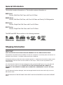
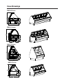
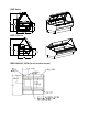
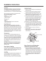
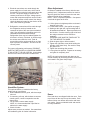
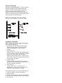
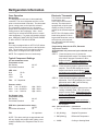
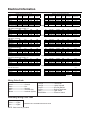
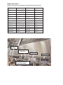
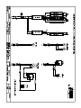
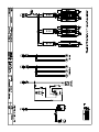
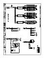
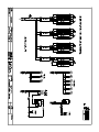
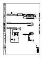
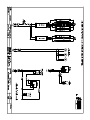
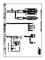
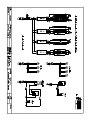
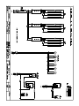
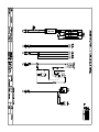
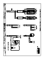
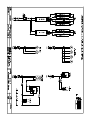
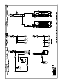
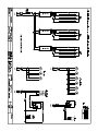
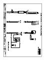
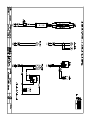
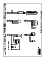
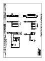
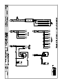
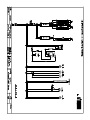
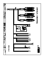
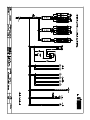
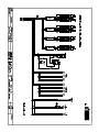
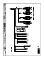
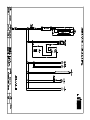
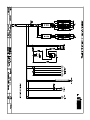
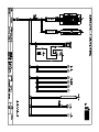
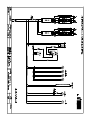
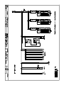
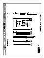
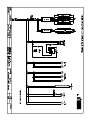
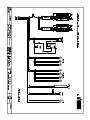
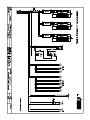
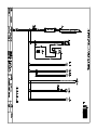
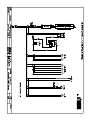
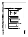
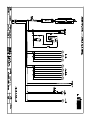
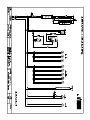
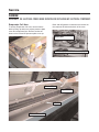
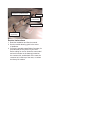
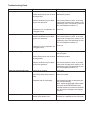
Service & Installation Instructions
Keep this booklet for future reference
BMD-48 SERIES
BMD-51 SERIES
BMD-54 SERIES
BMD-G SERIES
BSD SERIES
BSD-T SERIES
For Additional Copies Please Contact:
Barker Sales & Service
703 Franklin Street
P.O. Box 478
Keosauqua, Iowa 52565
Tel: 319/ 293-3777
Fax: 319/ 293-3776
Or Visit:
www.barkersales.com
Updated 5/21/07
Table of Contents
General Information
Electrical Information
Case Descriptions - - - - - - - - - - - - - - - - - - - - -3
Shipping Information - - - - - - - - - - - - - - - - - - -3
Case Sections
BMD Series - - - - - - - - - - - - - - - - - - - - - - - -4
BSD Series - - - - - - - - - - - - - - - - - - - - - - - -5
Mechanical View - - - - - - - - - - - - - - - - - - - - -5
Amperage Information - - - - - - - - - - - - - - - - -11
Wiring Color Code - - - - - - - - - - - - - - - - - - - -11
Ballast Information - - - - - - - - - - - - - - - - - - -12
Wiring Diagrams
BMD-R - - - - - - - - - - - - - - - - - - - - - - - - - - - -13
BMDG-R - - - - - - - - - - - - - - - - - - - - - - - - - -18
BSD-R - - - - - - - - - - - - - - - - - - - - - - - - - - - -23
BSDT-R - - - - - - - - - - - - - - - - - - - - - - - - - - -28
Installation Instructions
Location - - - - - - - - - - - - - - - - - - - - - - - - - - - -6
Crate Removal - - - - - - - - - - - - - - - - - - - - - - -6
Compressor - - - - - - - - - - - - - - - - - - - - - - - - -6
Case Exterior Loading - - - - - - - - - - - - - - - - - -6
Leveling - - - - - - - - - - - - - - - - - - - - - - - - - - - -6
Joining Lineups - - - - - - - - - - - - - - - - - - - - - - -6
Drain, Electrical and Refrigeration
Connections - - - - - - - - - - - - - - - - - - - - - - - - -6
Humidifier System - - - - - - - - - - - - - - - - - - - - -7
Glass Adjustment - - - - - - - - - - - - - - - - - - - - -7
Shelving - - - - - - - - - - - - - - - - - - - - - - - - - - - -8
Installation Checklist - - - - - - - - - - - - - - - - - - -8
Refrigeration Information
Case Operation - - - - - - - - - - - - - - - - - - - - - -9
Typical Component Settings - - - - - - - - - - - - -9
Electronic Thermostat - - - - - - - - - - - - - - - - - -9
Refrigeration Loads - - - - - - - - - - - - - - - - - - -10
BMD-SC - - - - - - - - - - - - - - - - - - - - - - - - - - -33
BMDG-SC - - - - - - - - - - - - - - - - - - - - - - - - -38
BSD-SC - - - - - - - - - - - - - - - - - - - - - - - - - - -43
BSDT-SC - - - - - - - - - - - - - - - - - - - - - - - - - -48
Maintenance Information
Cleaning - - - - - - - - - - - - - - - - - - - - - - - - - - -53
Light Bulb Replacement - - - - - - - - - - - - - - - -53
Load Limits - - - - - - - - - - - - - - - - - - - - - - - - -53
Service
Evaporator Coil Layout - - - - - - - - - - - - - - - -54
Troubleshooting Guide - - - - - - - - - - - - - - - -56
Service Department - - - - - - - - - - - - - - - - - - -57
Parts - - - - - - - - - - - - - - - - - - - - - - - - - - - - -57
Warranty - - - - - - - - - - - - - - - - - - - -58
IMPORTANT!!
KEEP FOR FUTURE REFERENCE
General Information
This booklet contains information on: This booklet contains information on:
BMD Series
Service, Multi-Deck Deli Case, with Front Lift Glass
BMDG Series
Service, Muti-Deck Deli Case, with Front Lift Glass and Gravity Coil Refrigeration
BSD Series
Service, Single Deck Deli Case, with Front Lift Glass
BSDT Series
Service, Single Deck Deli Case, with Front Tilt Glass
The BMD and BSD Series conform to the following standards
Shipping Information
IMPORTANT!
FOR YOUR PROTECTION PLEASE READ AND OBSERVE THE FOLLOWING INSTRUCTIONS:
Transportation companies assume all liability from the time a shipment is received by them until the time it is
delivered to the consumer. Our liability ceases at the time of shipment.
All shipments leaving our plant have been carefully inspected. If a shipment arrives with the crating or packaging damaged, have the carrier note the condition on the receipt. Check as soon as possible for concealed damage.
If it is found that the shipment has been damaged in transit, please DO NOT return it to us, but notify and
file a claim with the carrier at once. FAILURE TO FOLLOW THIS PROCEDURE WILL RESULT IN
REFUSAL BY THE CARRIER TO HONOR ANY CLAIMS WITH A CONSEQUENT LOSS TO THE CONSUMER.
If a UPS shipment has been damaged, retain the damaged material and the carton and notify us at once.
WE will file a claim.
GOODS SHOULD NOT BE RETURNED FOR CREDIT UNLESS AUTHORIZED BY OUR SALES DEPARTMENT.
Case Drawings
BMD-48 Series
BMD-51 Series
BMD-72 Series
BMD-G Series
BSD Series
BSD-T Series
MECHANICAL VIEW (for all models shown)
Installation Instructions
Location
This refrigerated display case has been designed
for displaying and storing perishable food product.
It is engineered for air-conditioned stores with a
maximum ambient of 75° F and 50% relative humidity.
When selecting the location for placement of this
case, avoid the following conditions:
Excessive air movement
• Doors
• Air-conditioned vents
• Other air sources
Excessive heat
• Windows
• Sun
• Flood lamps 8 feet or less from the product
• Other heat sources
Crate Removal
Move case as close as possible to its location.
Remove all crating and shipping braces above the
shipping pallet. Loosen the plastic dust cover from
the pallet, but leave cover over the case to protect it
while removing the case from the pallet. Carefully,
lift case up and off the pallet. Remove dust cover.
Installation hardware ships in an installation packet
located inside the case.
Joining Lineups
1. Begin all lineups leveling from the highest point
of the store floor.
2. Remove front and rear toe kicks by removing
screws on all sides. Set and level first case.
3. Apply foam tape to facing ends of lineup. Level
second case to first case and seal with a good
grade silicone on all edges of each case.
4. Line up bottom boltholes in lower toe kicks (bolts
for these are located in the installation packet
inside the case) and line up bolt stud located in
top rear strut with bolthole in adjoining case.
Slide cases together. Insert lower bolts and
place nuts on bolts. Tighten securely.
THE FRONT OF THE CASES MUST BE FLUSH!
5. A top joining plate is also located in the canopy
of the case. Ensure that case is properly leveled
so that the screw holes in this plate align over
the screw holes in the adjoining case. Shim as
necessary.
6. Screw in top plate and ensure all bolts are
fastened tightly.
7. Seal all seams. Use metal U-channel located
inside case to seal and cover where interior
case beds join.
Compressor
The 6', 8', 10 and 12' Self-Contained cases are
equipped with a shipping block under the compressor. This block must be removed upon installation.
Loosen all four nuts on the compressor hold down
screws. Lift or pry the compressor up and remove
the shipping block. DO NOT retighten screws, as
the compressor should be left free to float on the
spring mounts.
FAILURE TO REMOVE THE SHIPPING BLOCK
WILL RESULT IN EXCESSIVE NOISE, REFRIGERANT LEAKS AND WILL VOID WARRANTY
PROTECTION.
Case Exterior Loading
These cases are not designed for excessive external weight. DO NOT WALK ON THE TOP OF THE
CASES. Walking on top of cases could cause personal injury and damage to the case.
Leveling
To ensure proper operation of the refrigeration system and drainage of the condensate, the case
MUST BE LEVEL. Use a carpenter level to level
front to back and side to side. Shim as necessary.
Drain, Electrical and Refrigeration
Connections on Remote Cases
1. Drains are located in the center of the case.
Connect PVC drains to existing floor drains.
Provide as much downhill slope as possible and
avoid long runs of drain lines. Do not install
condensate drains in contact with non-insulated
suction lines in order to prevent condensate
from freezing. Install the 1" PVC trap, which is
provided with the case. All drains must be
trapped.
2. Electrical connections are made through the
power supply box of each case, which can be
accessed by removing the back panel above the
toe kick. The power supply is located in the
raceway as shown to the right. Voltage requirements and component amperes can be found in
the electrical section of this manual, but always
check the data tag located on the exterior of the
case. Case must be grounded.
3. Refrigeration connections will be made through
the refrigeration stub up located on the
customer left side of the case (see mechanical
view). See refrigeration information section for
caseloads and recommended settings.
Refrigeration lines may be headed together for
all cases in a lineup, if desired, by lines through
the access area under the case. Seal all
access holes with a good grade silicon or foam
tape to prevent recirculation. All lines must be
correctly sized.
For proper refrigeration performance, PRODUCT
MUST NOT BE PLACED IN A POSITION WHERE
IT MAY AFFECT THE AIR CURTAIN. Air discharge
and return air vents must remain unobstructed.
Glass Adjustment
Lift Glass is installed at the factory with the case
perfectly level, if adjustments need to be made to
align the glass first check to insure the case was
properly leveled during installation.
NOTE: This is a 2-person operation. One person
must hold the glass at all times.
1. Lift the glass to its highest position as shown in
drawing to the right.
2. Loosen allen screws. (See profile next page.)
3. Starting at the right side, tap the wedge with a
#2 standard screwdriver. Repeat procedure on
the left side. Continue working right to left until
the wedge recesses into the aluminum
extrusion.
EXTREME CARE MUST BE TAKEN NOT TO
TAP THE WEDGE TOO HARD.
4. Slide the glass right or left as needed.
5. Tighten the right allen screw while holding the
left side of the glass firmly. Be careful to keep
the glass level.
6. Tighten the remaining allen screws.
7. Lower glass into position. Repeat as necessary
until glass is completely level.
NOTE: the entire glass clamp and glass can be
moved sideways by loosening the allen screws that
are located in the glass clamp hinges.
Humidifier System This optional feature is installed at the factory.
Initial hook-up is as follows:
1. Read installation/service guide, which accompanies unit.
2. If connecting a lineup, which shares a common
control system, connect companion case dis
charge lines.
3. For all cases, connect water supply.
NOTE: It is recommended that a pre-filter be
added to the water supply.
4. Check for leaks.
Adjust water pressure as needed. See manufacturers installation guide for further information.
Doors
Rear load doors are shipped inside the case. Push
top of doors all the way into top door tracks. Push
bottom of door over bottom door tracks and lower
over tracks. Doors are labeled inside and outside
for easy installation.
Optional Shelving
Shelves are shipped separately. To place shelving,
hold shelf straight and fit brackets straight into
channel. Place shelf directly above light outlet.
Plug in light making certain the plug is fully
engaged. All cases with shelf lights are equipped
with an interlocking plug system. Shelf lights will not
operate if plugs are not fully seated.
NOTE: If the shelf light is not in use, the plug
attached to the receptacle must be fully seated.
Installation Checklist
Before supplying electrical power and starting
case check the following:
1. Compressor Area (For Self-contained cases).
Remove shipping block on units with semihermetic compressors. Check location of
controls.
2. Evaporator Area.
Check to ensure evaporator fan pressure plates
are secure and in proper position NOTE: Hinged
portion of pressure plates are secured for
shipping with mounting screws. Screws do not
have to be removed for case operation but must
be removed to use hinge.
3. Lighting System
Check to ensure male plugs are completely
inserted in female sockets and that all lamps are
securely seated in light fixture.
4. Case Leveling
Visually check case. If lift glass is out of
adjustment or case looks out of square, use a
carpenter's level and shim as needed.
After supplying power to the case and starting unit:
1. Check to ensure all fans are operational.
2. Check all lights.
3. Check case temperature and adjust thermostat
as needed. See refrigeration section of this manual
for case settings.
Refrigeration Information
Case Operation
Electronic Thermostat
Refrigeration
The refrigeration in this case is thermostatically
controlled. The case refrigerates until the cut out
point on the thermostat is reached. The thermostat
opens, cutting power to the liquid line solenoid.
The compressor continues to run, the system
pumps down causing the pressure switch to open,
cutting power to the compressor. Note: Some
cases may be ordered with EPR valves to control
case temperature. For proper refrigeration performance, PRODUCT MUST NOT BE PLACE WHERE
IT WILL AFFECT THE AIR CURTAIN.
The electronic thermostat is
located at the rear
of the case in the electronic
raceway. The thermostat is
equipped with a liquid crystal
display providing a constant
readout of the sensed temperature.
NOTE: The LCD display will be
blank during defrost. A touch
keypad that allows the users to
select the set point temperature, differential and the heating
/cooling modes.
Defrost
This case is equipped with an OFF CYCLE defrost
system. The timer cuts the power to the liquid solenoid. The unit stays in off cycle defrost until the
defrost timer re-energizes the liquid solenoid.
NOTE: The evaporator fan runs continuously.
Typical Component Settings
For Self Contained Cases
Thermostat cut out
Deli, Bakery
Fresh Meat, Seafood
CRO valve
R-22
404A
134A
TXV:
28°-30°
26°
55-58
75
N/A
Thermostat
Programming Steps for the ETC, Electronic
Temperature Control
All thermostats are pre-set and cycle checked at the
factory.
STEP 1: Press the set key once to access the
Fahrenheit/Celsius mode. The display will dis
play either F degrees Fahrenheit or C for
degrees Celsius. Press the up arrow or the
down arrow so the display indicates F.
STEP 2: Press the set key again to gain access to the
setpoint. The LCD will display the current
Setpoint and the S1 will be blinking. Press
the up arrow to increase or the down arrow
to decrease the temperature setting.
STEP 3: Press the set key again to gain access to the
differential. The LCD will display the current
differential and the DIF 1 will be blinking.
This should be set at 2°F.
10° Superheat
Pressure switch
R-22
Low - 20 lb/55 lb
404A Low - 20 lb/55 lb
134A
Low - 7 lb/25 lb
High - 350 lb
High - 350 lb
High - 225 lb
For Remote Cases
Thermostat cut out
Deli, Bakery
Fresh Meat, Seafood
28°-30°
26°
EPR Valve (saturated suction temp.)
Deli
18°-20°
Fresh Meat & Seafood
14°
TXV
Wiring
Schematic
10° superheat
NOTE: The above settings are approximate and
will vary slightly with product load, lighting, store
ambient conditions etc. Evaporator fans run constantly.
STEP 4: Press the set key again to gain access to the
cooling or heating mode. The LCD will dis
play the current mode. Press either the up
arrow or the down arrow to set the display in
the C1, cooling mode.
STEP 5: Press the set key once more and the pro
gramming is complete. Set the lock to keep
the set point.
STEP
DISPLAY INDICATION
DESCRIPTION
1. F or C
Fahrenheit or Celsius Scale
2. S1 (blinking)
Setpoint Temperature
3. DIF (blinking)
Differential Temperature
4. C1/H1
Cooling or Heating Mode
Refrigeration Loads
Model
BTU Lin/F t
BMD Series-enclosed base
BMD-4
650
BMD-6
650
BMD-8
650
BMD-10
650
BMD-12
650
Evap Temp
Defros t
+20o
+20o
+20o
+20o
+20o
20"/4hr.
20"/4hr.
20"/4hr.
20"/4hr.
20"/4hr.
BMD Series- pedestal base or bullet le gs
BMD-4
650
+20o
BMD-6
650
+20o
BMD-8
650
+20o
BMD-10
650
+20o
BMD-12
650
+20o
20"/4hr.
20"/4hr.
20"/4hr.
20"/4hr.
20"/4hr.
BMD Gravit y Coil Series
BMD-G-4
425
BMD-G-6
425
BMD-G-8
425
BMD-G-10
425
BMD-G-12
425
+15o
+15o
+15o
+15o
+15o
90"/24 hr.
90"/24 hr.
90"/24 hr.
90"/24 hr.
90"/24 hr.
BSD Series-enclosed base
BSD-4
450
BSD-6
450
BSD-8
450
BSD-10
450
BSD-12
450
+20o
+20o
+20o
+20o
+20o
20"/4hr.
20"/4hr.
20"/4hr.
20"/4hr.
20"/4hr.
BSD Series- pedestal base or bullet le gs
BSD-4
450
+20o
BSD-6
450
+20o
BSD-8
450
+20o
BSD-10
450
+20o
BSD-12
450
+20o
20"/4hr.
20"/4hr.
20"/4hr.
20"/4hr.
20"/4hr.
BSD Tilt Glass Series
BSD-T-4
450
BSD-T-6
450
BSD-T-8
450
BSD-T-10
450
BSD-T-12
450
20"/4hr.
20"/4hr.
20"/4hr.
20"/4hr.
20"/4hr.
+20o
+20o
+20o
+20o
+20o
Electrical Information
Remote Case Data - Electrical 120 Volt
Model
Evap Fans
Cornice &
Nose Lts
0.76
0.95
1.5
2.25
2.25
BMD Series-enclosed base
BMD-4
0.6
BMD-6
0.6
BMD-8
1.2
BMD-10
1.2
BMD-12
1.8
Additional Loads for Self-Contained Units
Shelf Lts
Anti-Sweat
Heaters
HP
Voltage
RLA/LRA
Cond
Fan
Pan Heater
0.49
0.75
0.95
1.54
1.54
NA
NA
NA
NA
NA
1/3
1/2
3/4
1
1
120-1-60
120-1-60
120-1-60
120-208 1-60
120-208 1-60
5.6/29
9.4/51
9.8/65
5.7/40
5.7/40
0.58
1.4
1.7
0.94
0.94
5.0
6.6
8.3
4.8
4.8
0.52
0.78
1.04
1.3
1.56
1/3
1/2
3/4
1
1
120-1-60
120-1-60
120-1-60
120-208 1-60
120-208 1-60
5.6/29
9.4/51
9.8/65
5.7/40
5.7/40
0.58
1.4
1.7
0.94
0.94
5.0
6.6
8.3
4.8
4.8
0.26
0.52
0.52
0.52
0.78
Air Sweep Fan
Add 5 amps if a humidification system is added. A separate power source is not needed.
BMD Series- pedestal base or bullet le gs
BMD-4
0.55
0.76
BMD-6
1.1
0.95
BMD-8
1.1
1.5
BMD-10
1.1
1.54
BMD-12
1.65
1.54
0.49
1.75
0.95
1.54
1.54
2.08
4.16
4.16
4.16
6.24
Add 5 amps if a humidification system is added. A separate power source is not needed.
BMD Gravit y Coil Series
BMD-G-4
NA
BMD-G-6
NA
BMD-G-8
NA
BMD-G-10
NA
BMD-G-12
NA
0.76
0.95
0.95
1.54
1.54
NA
NA
NA
NA
NA
NA
NA
NA
NA
NA
1/2
1/2
3/4
1
1
120-1-60
120-1-60
120-1-60
120-1-60
120-1-60
7/36
9.4/51
11.8/66.3
8.2/65
11.4/93
0.7
1.3
1.64
1.7
1.7
5.0
6.6
8.3
8.3
8.3
0.52
0.78
1.04
1.3
1.56
BSD Series-enclosed base
BSD-4
0.6
BSD-6
0.6
BSD-8
1.2
BSD-10
1.2
BSD-12
1.8
0.76
0.95
1.5
2.25
2.25
NA
NA
NA
NA
NA
NA
NA
NA
NA
NA
1/3
1/2
3/4
1
1
120-1-60
120-1-60
120-1-60
120-208 1-60
120-208 1-60
5.6/29
9.4/51
9.8/65
5.7/40
5.7/40
0.58
1.4
1.7
0.94
0.94
5.0
6.6
6.6
4.8
4.8
0.52
0.78
1.04
1.3
1.56
1/3
1/2
3/4
1
1
120-1-60
120-1-60
120-1-60
120-208 1-60
120-208 1-60
5.6/29
9.4/51
9.8/65
5.7/40
5.7/40
0.58
1.4
1.7
0.94
0.94
5.0
6.6
6.6
4.8
4.8
0.26
0.52
0.52
0.52
0.78
1/3
1/2
3/4
1
1
120-1-60
120-1-60
120-1-60
120-208 1-60
120-208 1-60
5.6/29
9.4/51
9.8/65
5.7/40
5.7/40
0.58
1.4
1.7
0.85
0.85
5.0
6.6
6.6
4.8
4.8
0.52
0.78
1.04
1.3
1.56
Add 5 amps if a humidification system is added. A separate power source is not needed.
BSD Series- pedestal base or bullet le gs
BSD-4
0.6
0.76
BSD-6
0.6
0.95
BSD-8
1.2
1.5
BSD-10
1.2
1.54
BSD-12
1.8
1.54
NA
NA
NA
NA
NA
2.08
4.16
4.16
4.16
6.24
Add 5 amps if a humidification system is added. A separate power source is not needed.
BSD Tilt Glass Series
BSD-T-4
BSD-T-6
BSD-T-8
BSD-T-10
BSD-T-12
Fans
0.6
1.2
1.2
1.2
1.8
NA
NA
NA
NA
NA
NA
NA
NA
NA
NA
DRY CASES - USE LIGHTING SPECIFICATIONS
NA
NA
NA
NA
NA
REMOTE CASES - 20 MINUTES DEFROST EVERY 4 HOURS
Wiring Color Code
Green------------------------Ground
Black-------------------------Hot
White ------------------------Neutral
Red --------------------------208/220 Only
Brown -----------------------Interlock System
Orange ----------------------Thermostat
Orange ----------------------Liquid Solenoid
Purple -----------------------Hot Gas Defrost
Purple -----------------------Defrost Terminator
Gray -------------------------Light Switch
Black/White ----------------Pressure Switch
Secondary Wiring Color Code
Red ----------Lights
Yellow -------Lights
Blue----------Lights
SEE BALLAST DIAGRAM FOR EACH CASE
NOTE: Case must be grounded
Ballast Information
Ballasts are located in the electronic raceway at the rear of the case.
Model
Model
BMD-4
(1) 3P, (1) 2P
BSD-4
(1) 3P
BMD-6
(2) 4P, (1) 2P
BSD-6
(1) 4P, (1) 2P
BMD-8
(2) 4P, (1) 2P
BSD-8
(1) 4P, (1) 2P
BMD-10
(5) 2P
BSD-10
(3) 2P
BMD-12
(5) 3P
BSD-12
(3) 3P
BMD-4G
(1) 3P
BSD-4T
(1) 2P
BMD-6G
(1) 4P, (1) 2P
BSD-6T
(1) 2P
BMD-8G
(1) 4P, (1) 2P
BSD-8T
(1) 2P
BMD-10G
(2) 4P
BSD-10T
(1) 3P
BMD-12G
(3) 3P
BSD-12T
(1) 3P
LH and RH Shelf
Ballast Boxes
Nose light and Canopy
Ballast Boxes
Digital Thermostat
Main Power Supply
Ballast and Light Terminal and
Light Power Supply Terminal
Maintenance Information
Cleaning
Case Exterior
Clean surfaces frequently with warm water and mild
detergent. Do not use strong alkali solutions, steel
wool, or abrasive cleansers.
Non-Glare Glass
Non-glare glass surfaces are coated to reduce the
glare from lighting. Care must be taken not to
scratch the coating. Use the following products only.
Cleaning Cloths
Scotch-Brite High Performance Cloth - manufactured by 3M and available in most grocery stores
under the name Scothch-Brite Microfiber Cleaning
Cloth in a 12" x14" size. This cloth is washable and
may be reused as long as it remains clean.
Spontex Microfibre Cleaning Cloth - distributed
by Spontex and available in most grocery stores
under the same name in a 15.75" x 12" size. This
cloth is washable and may be reused as long as it
remains clean.
The cleaning cloths named above will normally
remove dust, grease, oil and fingerprints without the
need for cleaning fluids. A light spray of the cleaning fluids listed below will reduce the time required
for cleaning.
Cleaning Fluid - for more difficult cleaning jobs,
these products are recommended:
Windex - standard product only (extra-strength
or specialty products may not be suitable)
Glass-Plus - standard product only (extrastrength or specialty products may not be suiable)
Warm Water
DO NOT USE the following types of materials can
be used for cleaning glass with anti-reflective
coatings.
Coarse Paper Towels
Scouring Pads or Powders
Steel wool or Steel Fiber Materials
Blades
Acidic or highly Alkaline detergents
Fluorine based detergents
Case Interior
All shelving and lower deck can be removed for
cleaning (See installation instructions for removing
and setting shelving). Check to make sure the
case drain(s) are not clogged. Clean interior with
warm water and a mild detergent. A sanitizer
should be used after washing to eliminate bacteria.
Rinse thoroughly being careful not to flood drain
system. Avoid spraying water directly into electrical
connections. DO NOT USE A HIGH PRESSURE
WATER HOSE. MAKE SURE FANS ARE SHUT
OFF WHEN CLEANING THE INTERIOR OF THE
CASE. Drains should be cleaned once a month.
Evaporator Coil
Clean as needed.
Condenser Coil
FAILURE TO CLEAN COILS WILL VOID WARRANTY. Clean condenser coil every three months or as
needed with a whisk broom or vacuum. Disconnect
power when servicing. FINS ON CONDENSER
COIL ARE SHARP!
Condensate Heater
(Evap-O-Way)
Add one teaspoon of scale remover or white vinegar to condensate heater pan once every three
months or as needed. Heater is designed for 75º
and 50% relative humidity. The condensate pan
may overflow if design limits are exceeded.
Seafood Application
Plexiglas should be removed for cleaning. Reinstall
Plexiglas by placing in front of case. Ice will hold it
in place. PLEXIGLAS MUST BE IN PLACE TO
KEEP ICE OUT OF AIR SCREEN.
Light Replacement
The fluorescent lights in this case are furnished with
plastic safety shields and end caps. When replacing fluorescent lamps, be certain to reinstall safety
shield and caps. (See illustration). If the bulb is not
fully seated the lights will not operate. BE SURE
BULBS ARE FULLY SEATED.
The light switch is mounted to the right side of the
ceiling. See mechanical drawing for ballast box
location.
A. To remove bulb, grasp lamp
holder on either end of the bulb
and with equal pressure pull
down.
B. Install new bulb into the
plastic safety tube protector.
Insert bulb into end cap.
lamp holder
cap
bulb in safety tube
C. Position the bulb and cap
under the lamp holder
and with even pressure
press the bulb into the
light fixture.
Caution: Failure to install bulb fully into light socket will cause
premature bulb life and may cause damage to light fixture
Load Limits
DO NOT place product in merchandisers until all
refrigeration controls have been adjusted and are at
the proper operating temperature. DO NOT place
product above load limits or in such a way that the
discharge or return air grill are blocked. This will
effect the performance of the case and effect the
defrost system.
Service
WARNING!
DISCONNECT THE ELECTRICAL POWER WHEN SERVICING OR REPLACING ANY ELECTRICAL COMPONENT.
Evaporator Coil Area
To access Evaporator Coil area, remove bottom
deck by lifting up and out to expose pressure plate
cover and evaporator fans. Remove screws as
shown to the left and lift pressure plate cover up.
Drain and refrigeration connections are located on
the customer left side at the back of the case.
Liquid and suction line refrigeration
connection points
1" PVC running trap with 11/2" to 1" reducer coupling
Evaporator Fans
Pressure Plate
Evaporator Coil
Drain
Washout Drain Pan
Thermo static expansion valve
Refrigerant is predetermined.
TXV Bulb
Schrader valve
(suction line)
Drain Pan Access
Solenoid valve
(liquid line)
Service Instructions
1. Read the Installation and Service manual.
2. See the trouble-shooting guide in the event
of problems.
3. If service is needed contact Barker Company for
an authorized service person in your area.
Before calling for service locate the case model
and serial number on the data tag located on
the customer left, outside back of the case, the
customer left, inside top of the case, or contact
the factory for location.
Troubleshooting Guide
Problem
Case temperature is too warm.
Cause
Case is in defrost.
Action
Review T-Stat settings.
Product load may be over its limits Redistribute product.
blocking airflow.
Case temperature is too cold.
Condensation on glass.
Ambient conditions may be affecting the case operation.
Check case position in store. Is the case
located near an open door, window, or air
conditioning vent?. RH should not be over
50% and temperature above 75º.
Condensing coil or evaporator coil
is clogged or dirty.
Clean coil.
The T-Stat Temp is set too low.
Ambient conditions may be affecting the case operation.
Check setting. See factory guidelines.
Check case position in store. Is the case
located near an open door, window, or air
conditioning vent? RH should not be over
50% and temperature above 75º.
Condensing coil or evaporator coil
is clogged or dirty.
Clean coil.
Inadequate air circulation.
Check grill on die board for adequate airflow over glass.
Product load may be over its limits Redistribute product.
blocking airflow.
Water has pooled under case.
Frost or ice on evaporator coil.
Ambient conditions may be affecting the case operation.
Check case position in store. Is the case
located near an open door, window, or air
conditioning vent? RH should not be over
50% and temperature above 75º.
Case drain is clogged.
Clear drain.
Check PVC drains under case for
leaks.
Repair as needed.
Evaporator pan is overflowing.
Check electrical supply to dissipater pan.
Check float assembly.
(Note: Cases equipped with electric dissipater pans should NEVER have food
products washed or poured into the drain
as it will result in damage to the heating
element.)
Check evaporator fans.
Defrost clock doesn't work.
Check electrical connections. Have unit
serviced by a qualified service technician.
Barker Sales & Service Department
IMPORTANT INFORMATION!
FOR PROMPT SERVICE WHEN CONTACTING THE FACTORY FOR SUPPORT, BE SURE TO HAVE CASE MODEL AND SERIAL
NUMBER HANDY.
(THIS INFORMATION IS LOCATED ON THE DATA TAG ATTACHED TO THE CASE. SEE BELOW FOR DATA TAG LOCATIONS)
For any warranty or service issues not covered by this manual, for tech support, or for warranty service calls, please
contact the Barker Service Manager in your area.
Jody Jones - Eastern Service
• Connecticut
• Georgia
• Massachusetts
• New York (Eastern)
• Rhode Island
• Virginia
Manager: (319) 293-8308
• Delaware
•
• Maine
•
• New Hampshire
•
• North Carolina
•
• South Carolina
•
Florida
Maryland
New Jersey
Pennsylvania (Eastern)
Vermont
Bill Connor - Midwestern Service Manager: (319) 293-8307
• Alabama
• Arkansas
• Indiana
• Iowa
• Kansas
• Kentucky
• Louisiana
• Michigan
• Mississippi
• Missouri
• Nebraska
• New York (Western)
• Ohio
• Oklahoma
• Pennsylvania (Western)
• Tennessee
• West Virginia
Gregg Rupe - 2nd Midwestern
• Alaska
• Hawaii
• Minnesota
• Texas
Service Manager: (319) 293-8324
• CANADA
• EUROPE
• Illinois
• MEXICO
• North Dakota
• South Dakota
• Wisconsin
Gary Winslow - Western Service Manager: (319) 293-8306
• Arizona
• California
• Colorado
• Idaho
• Montana
• Nevada
• New Mexico
• Oregon
• Utah
• Washington
• Wyoming
Parts
Ordering Procedure
1.
Contact the Service Parts Department
Melissa Marshall
703 Franklin Street
PO Box 478
Keosauqua, IA 52565
Tel: 319-293-8323
Fax: 319-293-8377
[email protected]
2.
Provide the serial number of the case containing the part.
To locate the serial number look on the data tag located on the
customer left, outside back of the case, the customer left, inside
top of the case, or contact the factory for location.
3.
If parts are to be returned for credit, contact the Parts
Department. Do not send parts without authorization.
BEFORE SERVICING
ALWAYS DISCONNECT ELECTRICAL
POWER AT THE MAIN DISCONNECT
WHEN SERVICNG OR REPLACING
ANY ELECTRICAL COMPONENT.
One Year Factory Warranty
703 Franklin Street
P.O. Box 478
Keosauqua, Iowa 52565
Tel:319/293-3777
Fax:319/293-3776
www.barkersales.com
For all shipments with original delivery points in the continental U.S. but with a final destinations outside the continental U.S., Barker Company warrants to the original purchaser that every new Barker merchandiser, the cabinet
and all parts thereof, to be free from defects in material or workmanship, under normal use and service, for a period of one (1) year from the date of original installation or 15 months after shipment date from Barker Company,
whichever occurs first.
Barker Company will replace, in its sole and absolute discretion, without cost to the original equipment purchaser,
any part or parts thereof, which inspection by Barker Company or proven to the satisfaction of the Company to
have been defective. Replacement parts will be shipped to the original point of shipment. Any installation and / or
service work will be at the expense of the original purchaser.
For all shipments within the continental U.S. , Barker Company warrants to the original purchaser that every new
Barker merchandiser, the cabinet and all parts thereof, to be free from defects in material or workmanship, under
normal use and service, for a period of (1) year from the date of original installation or 15 months after shipment
date from Barker Company, whichever occurs first.
Barker Company will replace, in its sole and absolute discretion, without cost to the original equipment purchaser,
any part or parts thereof, which inspection by Barker Company or proven to the satisfaction of the Company to
have been defective.
All warranty service work must be pre-authorized by Barker Company (800-814-0446). Barker Company reserves
the rights to designate the service provider, time in which labor is to be performed and specify amount of time per
warranty problem.
COMPRESSOR WARRANTY: The standard compressor warranty is for a period of one (1) year from the date of
original installation or 15 months after shipment date. A four-year compressor warranty extension is available at an
additional cost to the original purchaser/user. If compressor issues arise after the initial warranty period expires,
please provide the Company with the applicable serial number to determine whether a four-year compressor warranty extension was purchased prior to the ship date.
What is NOT Covered by Factory Warranty
This Limited Warranty also does not apply to any equipment, or parts thereof, that has been subject to misuse,
neglect, accident, misapplication or problems caused by improper installation and/or lack of periodic maintenance.
This Limited Warranty does not include glass breakage.
Barker Company shall under no circumstances be responsible for any loss, cost of damage beyond repair or
replacement, whether incidental or consequential, other than specifically identified in the foregoing Limited
Warranty including but not limited to any spoilage, shrinkage or damage to commodities or product during installation or operation of the Company's equipment caused by failure of refrigeration, or loss of business resulting therefrom.
WARRANTY CLAIMS. All claims should include: the serial number of the cabinet, proof of purchase, date of installation, and all pertinent information supporting the existence of the alleged defect. Any action for breach of these
warranty provisions must be commenced within one (1) year after that cause of action has accrued.
WARRANTY REGISTRATION CARD
This card must be mailed
immediately after installation
date to the address below for
warranty to be in effect.
P.O. Box 478
Keosauqua, IA 52565
(Name of company purchaseing merchandiser)
(Type of business)
(City & State of Purchaser)
(Cabinet Serial #)
(Date of installation)
(Signature of store owner)
Failure to forward this Warranty Registration Card within 21 days of installation
VOIDS ANY AND ALL WARRANTIES, whether by contract or at law.