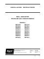
1
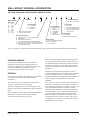
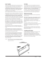
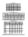
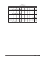
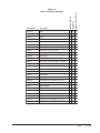
INSTALLATION
INSTRUCTIONS
WALL MOUNTED
PACKAGE AIR CONDITIONERS
MODELS
W17A1
W17L1
W18A1
W18L1
W24A1
W24L1
W30A1
W30L1
W36A1
W36L1
W42A1
W42L1
W48A1
W48L1
W60A1
W60L1
W70A1
W70L1
Bard Manufacturing Company, Inc.
Bryan, Ohio 43506
Since 1914...Moving ahead just as planned.
Manual :
Supersedes:
File:
Date:
2100-508F
2100-508E
Volume III Tab 16
12-15-11
Manual
Page
2100-508F
1 of 25
Contents
Getting Other Information and Publications
Wall Mount General Information
Wall Mount Model Nomenclature ............................
Shipping Damage ....................................................
General ................................................................
Duct Work ................................................................
Filters
................................................................
Fresh Air Intake .......................................................
Condensate Drain ....................................................
3
4
4
4
5
5
5
5
Installation Instructions
Wall Mounting Information ....................................... 6
Mounting the Unit .................................................... 6
Clearances Required ............................................... 6
Minimum Clearances ............................................... 6
Wiring – Main Power ............................................. 14
Wiring – Low Voltage Wiring ................................. 14
Figures
Figure 1
Figure 2
Figure 3A
Figure 3B
Figure 3C
Figure 4
Figure 5
Figure 6
Figure 7
Figure 8
Fresh Air Damper Assembly ................... 5
Unit Dimensions ...................................... 7
Mounting Instructions .............................. 8
Mounting Instructions - W17 – 36 .............. 9
Mounting Instructions - W42, 48, 60, 70 ... 10
Electric Heat Clearance ......................... 11
Wall Mounting Instructions .................... 12
Wall Mounting Instructions .................... 12
Common Wall Mounting Installations .... 13
Fan Blade Setting ................................. 18
Manual 2100-508F
Page
2 of 25
Start Up
General ..............................................................
Topping Off System Charge ...................................
Safety Practices .....................................................
Important Installer Note .........................................
High Pressure Switch ............................................
Three Phase Scroll Compressor ............................
Phase Monitor .......................................................
Condenser Fan Operation .....................................
Service Hints .........................................................
Sequence of Operation ..........................................
Compressor Control Module ..................................
Adjustments ...........................................................
Pressure Service Ports ..........................................
15
15
15
16
16
16
16
16
16
17
17
17
17
Troubleshooting
Fan Blade Setting Dimensions .............................. 18
Removal of Fan Shroud ......................................... 18
Refrigerant Charge ................................................ 18
Tables
Table 1
Table 2
Table 3
Table 4
Table 5
Table 6
Table 7
Table 8
Table 9
Table 10
Fan Blade Dimensions ..........................
Cooling Pressure ..................................
Electrical Specifications W**A ..............
Electrical Specifications W**L ...............
Recommended Airflow ..........................
Indoor Blower Performance ..................
Maximum ESP Electric Heat Only ........
Electric Heat .........................................
Optional Accessories ............................
Vent & Control Options .........................
18
19
20
21
22
22
22
23
24
25
GETTING OTHER INFORMATION AND PUBLICATIONS
These publications can help you install the air
conditioner or heat pump. You can usually find these at
your local library or purchase them directly from the
publisher. Be sure to consult current edition of each
standard.
FOR MORE INFORMATION, CONTACT
THESE PUBLISHERS:
ACCA
Air Conditioning Contractors of America
1712 New Hampshire Ave. N.W.
Washington, DC 20009
Telephone: (202) 483-9370
Fax: (202) 234-4721
ANSI
American National Standards Institute
11 West Street, 13th Floor
New York, NY 10036
Telephone: (212) 642-4900
Fax: (212) 302-1286
National Electrical Code ...................... ANSI/NFPA 70
Standard for the Installation .............. ANSI/NFPA 90A
of Air Conditioning and Ventilating Systems
Standard for Warm Air ...................... ANSI/NFPA 90B
Heating and Air Conditioning Systems
Load Calculation for ............................ ACCA Manual J
Residential Winter and Summer Air Conditioning
Duct Design for Residential .............. ACCA Manual D
Winter and Summer Air Conditioning and Equipment
Selection
ASHRAE American Society of Heating, Refrigeration
and Air Conditioning Engineers, Inc.
1791 Tullie Circle, N.E.
Atlanta, GA 30329-2305
Telephone: (404) 636-8400
Fax: (404) 321-5478
NFPA
National Fire Protection Association
Batterymarch Park
P.O. Box 9101
Quincy, MA 02269-9901
Telephone: (800) 344-3555
Fax: (617) 984-7057
Manual 2100-508F
Page
3 of 25
WALL MOUNT GENERAL INFORMATION
AIR CONDITIONER WALL MOUNT MODEL NOMENCLATURE
W
42
A
1
–
A
10
X
X
X
X
KW
CAPACITY
18 - 1½ Ton
24 - 2 Ton
30 - 2½ Ton
36 - 3 Ton
42 - 3½ Ton
48 - 4 Ton
60 - 5 Ton
70 - 6 Ton
VOLTS & PHASE
A - 230/208/60/1
B - 230/208/60/3
C - 460/60/3
A - Right Hand Air Conditioner
L - Left Hand Air Conditioner
VENTILATION OPTIONS
X - Barometric Fresh Air Damper (Standard)
B - Blank-off Plate
M - Motorized Fresh Air Damper
V - Commercial Ventilator - Motorized with Exhaust
E - Economizer (Internal) - Fully Modulating with Exhaust
R - Energy Recovery Ventilator - Motorized with Exhaust
(See Spec. Sheet S3397)
A
CONTROL MODULES
(See Spec. Sheet S3397)
REVISIONS
MODEL NUMBER
X
COIL OPTIONS
X - Standard
COLOR OPTIONS
1 - Phenolic Coated Evaporator
X - Beige (Standard)
2 - Phenolic Coated Condenser
1 - White
3 - Phenolic Coated Evaporator
4 - Buckeye Gray
and Condenser
5 - Desert Brown
6 - Dark Bronze
OUTLET OPTIONS
A - Aluminum
X - Front (Standard)
S - Stainless Steel
T - Top Outlet (W30A, W36A Only)
FILTER OPTIONS
X - One Inch Throwaway (Standard)
W - One Inch Washable
P - Two Inch Pleated
NOTE: Vent options X, B and M are without exhaust capability. May require separate field supplied barometric relief in building.
SHIPPING DAMAGE
Upon receipt of equipment, the carton should be
checked for external signs of shipping damage. If
damage is found, the receiving party must contact the
last carrier immediately, preferably in writing,
requesting inspection by the carrier’s agent.
GENERAL
The equipment covered in this manual is to be installed
by trained, experienced service and installation
technicians.
The refrigerant system is completely assembled and
charged. All internal wiring is complete.
The unit is designed for use with or without duct work.
Flanges are provided for attaching the supply and return
ducts.
These instructions explain the recommended method to
install the air cooled self-contained unit and the
electrical wiring connections to the unit.
Manual 2100-508F
Page
4 of 25
These instructions and any instructions packaged with
any separate equipment required to make up the entire
air conditioning system should be carefully read before
beginning the installation. Note particularly “Starting
Procedure” and any tags and/or labels attached to the
equipment.
While these instructions are intended as a general
recommended guide, they do not supersede any national
and/or local codes in any way. Authorities having
jurisdiction should be consulted before the installation is
made. See Page 3 for information on codes and
standards.
Size of unit for a proposed installation should be based
on heat loss calculation made according to methods of
Air Conditioning Contractors of America (ACCA). The
air duct should be installed in accordance with the
Standards of the National Fire Protection Association
for the Installation of Air Conditioning and Ventilating
Systems of Other Than Residence Type, NFPA No.
90A, and Residence Type Warm Air Heating and Air
Conditioning Systems, NFPA No. 90B. Where local
regulations are at a variance with instructions, installer
should adhere to local codes.
DUCT WORK
FILTERS
All duct work, supply and return, must be properly sized
for the design airflow requirement of the equipment. Air
Conditioning Contractors of America (ACCA) is an
excellent guide to proper sizing. All duct work or portions
thereof not in the conditioned space should be properly
insulated in order to both conserve energy and prevent
condensation or moisture damage.
A 1-inch throwaway filter is standard with each unit.
The filter slides into position making it easy to service.
This filter can be serviced from the outside by removing
the filter access panel. A 1-inch washable filter and 2inch pleated filter are also available as optional
accessories. The internal filter brackets are adjustable
to accommodate the 2-inch filter by bending two (2)
tabs down on each side of the filter support bracket.
Refer to Maximum ESP of operation Electric Heat Table 6.
Design the duct work according to methods given by the Air
Conditioning Contractors of America (ACCA). When duct
runs through unheated spaces, it should be insulated with a
minimum of one inch of insulation. Use insulation with a
vapor barrier on the outside of the insulation. Flexible joints
should be used to connect the duct work to the equipment in
order to keep the noise transmission to a minimum.
Models W17 - W24 as approved for zero inch clearance to
the supply duct. For model series W30, W36, W42, W48,
W60 and W70 a 1/4 inch clearance to combustible material
for the first three feet of duct attached to the outlet air frame
is required. See Wall Mounting Instructions and Figures 3
and 4 for further details.
Ducts through the walls must be insulated and all joints
taped or sealed to prevent air or moisture entering the wall
cavity.
Some installations may not require any return air duct. A
metallic return air grille is required with installations not
requiring a return air duct. The spacing between louvers on
the grille shall not be larger than 5/8 inch.
Any grille that meets with 5/8 inch louver criteria may be
used. It is recommended that Bard Return Air Grille Kit
RG2 through RG5 or RFG2 through RFG5 be installed
when no return duct is used. Contact distributor or factory
for ordering information. If using a return air filter grille,
filters must be of sufficient size to allow a maximum
velocity of 400 fpm.
FRESH AIR INTAKE
All units are built with fresh air inlet slots punched in
the service door.
If the unit is equipped with a fresh air damper assembly,
the assembly is shipped already attached to the unit.
The damper blade is locked in the closed position. To
allow the damper to operate, the maximum and
minimum blade position stops must be installed. See
Figure 1.
All capacity, efficiency and cost of operation
information is based upon the fresh air blank-off plate in
place and is recommended for maximum energy
efficiency.
The blank-off plate is available upon request from the
factory and is installed in place of the fresh air damper
shipped with each unit.
CONDENSATE DRAIN
A plastic drain hose extends from the drain pan at the
top of the unit down to the unit base. There are
openings in the unit base for the drain hose to pass
through. In the event the drain hose is connected to a
drain system of some type, it must be an open or vented
type system to assure proper drainage.
NOTE: If no return air duct is used, applicable installation
codes may limit this cabinet to installation only in a
single story structure.
FIGURE 1
FRESH AIR DAMPER
Manual 2100-508F
Page
5 of 25
INSTALLATION INSTRUCTIONS
WALL MOUNTING INFORMATION
1. Two holes for the supply and return air openings
must be cut through the wall as shown in Figure 3.
2. On wood frame walls, the wall construction must be
strong and rigid enough to carry the weight of the
unit without transmitting any unit vibration.
3. Concrete block walls must be thoroughly inspected
to insure that they are capable of carrying the weight
of the installed unit.
WARNING
Failure to provide the 1/4 inch clearance
between the supply duct and a combustible
surface for the first 3 feet of duct can result in
fire causing damage, injury or death.
MOUNTING THE UNIT
1. These units are secured by wall mounting brackets
which secure the unit to the outside wall surface at
both sides. A bottom mounting bracket, attached to
skid for shipping, is provided for ease of installation,
but is not required.
2. The unit itself is suitable for 0 inch clearance, but
the supply air duct flange and the first 3 feet of
supply air duct require a minimum of 1/4 inch
clearance to combustible material for model series
W30, W36, W42, W48, W60 and W70. However, it
is generally recommended that a 1-inch clearance is
used for ease of installation and maintaining the
required clearance to combustible material. See
Figure 3 for details on opening sizes.
3. Locate and mark lag bolt locations and bottom
mounting bracket location. See Figure 3.
6. Position unit in opening and secure with 5/16 lag
bolts; use 7/8 inch diameter flat washers on the lag
bolts.
7. Secure rain flashing to wall and caulk across entire
length of top. See Figure 3.
8. For additional mounting rigidity, the return air and
supply air frames or collars can be drilled and
screwed or welded to the structural wall itself
(depending upon wall construction). Be sure to
observe required clearance if combustible wall.
9. On side-by-side installations, maintain a minimum
of 20 inches clearance on right side to allow access
to control panel and heat strips, and to allow proper
airflow to the outdoor coil. Additional clearance
may be required to meet local or national codes.
4. Mount bottom mounting bracket.
5. Hook top rain flashing, attached to front - right of
supply flange for shipping, under back bend of top.
Clearances Required for Service A ccess
and A dequate Condenser A irflow
Minimum Clearances Required to
Combustible Materials
MOD ELS
W17A, W18A, W24A, W30A, W36A
W17L, W18L, W24L, W30L, W36L
W42A, W48A, W60A, W70A
W42L, W48L, W60L, W70L
SU P P LY AIR D U C T
C AB IN ET
FIR ST TH R EE FEET
W17A, L / W18A, L / W24A, L
0"
0"
W30A, L / W36A, L
1/4"
0"
W42A, L / W48A, L
1/4"
0"
W60A, L / W70A, L
LEFT SID E
15"
20"
20"
20"
R IGH T SID E
20"
15"
20"
20"
NOTE: For side by side installation of two (2) W**A models there
must be 20" between units. This can be reduced to 15" by using
a W**L model (left side compressor and controls) for the left unit
and WA (right side compressor and controls) for right unit.
See W**A Specification S3397 & W**L Specification S3400.
Manual 2100-508F
Page
6 of 25
MOD ELS
FIGURE 2
Dimensions of Basic Unit for A rchitectural and Installation Requirements (Nominal)
MOD EL
WID TH D EPTH HEIGHT SUPPLY
(W)
(D )
(H)
A
B
RETURN
C
B
E
F
G
I
J
K
L
M
N
O
P
Q
R
S
T
W17A, L
W18A, L 33.300 17.125 70.563 7.88 19.88 11.88 19.88 35.00 11.00 25.75 20.56 26.75 28.06 29.25 27.00 2.63 34.13 22.06 10.55 4.19 12.00 5.00
W24A, L
W30A, L
38.200 17.125 70.563 7.88 27.88 13.88 27.88 40.00 11.00 25.75 17.93 26.75 28.75 29.25 27.00 2.75 39.19 22.75 9.14 4.19 12.00 5.00
W36A, L
W42A, L
W48A, L 42.075 22.432 84.875 9.88 29.88 15.88 29.88 43.88 13.63 31.66 30.00 32.68 26.94 34.69 32.43 3.37 42.88 23.88 10.00 1.44 16.00 1.88
W60A, L
W70A, L 42.075 22.432 94.875 9.88 29.88 15.88 29.88 43.88 13.63 41.66 30.00 42.68 36.94 44.69 42.43 3.37 42.88 33.88 10.00 1.44 16.00 1.88
All dimensions are in inches. Dimensional drawings are not to scale.
W**A
RIGHT
UNIT
Built In
Rain Hood
4° Pitch
W
E
O
D
7.88
2
1.00
Heater
Access
Panel
2
.44
2.13
R
Side Wall
Mounting
Brackets
(Built In)
A
Electric
Heat
Supply Air Opening
S
B
C. Breaker/
Disconnect
Access Panel
(Lockable)
I
Top Rain
Flashing
Shipping
Location
Filter Access
Panel
5.75
31.88
2
Vent Option
Door
C H
S
Optional
Electrical
Entrances
Return Air Opening
S
Ventilation
Air
F
S
Low Voltage
Electrical
Entrance
G
K
Cond.
Air
Inlet
High Voltage
Electrical
Entrance
Condenser
Air Outlet
1
L
J
M
S
P
1
T
Front View
Drain
Side View
N
Back View
Q
1
2
Bottom Installation
Bracket
MIS-2487 B
Dimension is 21.00 inches on W70A & W70L models.
Optional top outlet (factory installed only) for W30A and W36A models only.
E
O
.44
W**L
LEFT
UNIT
R
D
Side Wall
Mounting
Brackets
(Built In)
Supply Air Opening
S
S
Optional
Electrical
Entrances
Return Air Opening
S
1
Electric
Heat
A
Heater
Access
Panel
M
1
P
W
C. Breaker/
Disconnect
Access Panel
(Lockable)
Filter Access
Panel
Ventilation
Air
Vent Option
Door
C
H
L
S
2.13
I
Top Rain
Flashing
Shipping
Location
S
Built In
Rain Hood
4° Pitch
5.75
F
Low Voltage
Electrical
Entrance
K
J
Cond.
Air
Inlet
High Voltage
Electrical
Entrance
Condenser
Air Outlet
G
T
Drain
Bottom
Installation
Bracket
2.63
Back View
Side View
Front View
MIS-2488 B
9.06
Manual 2100-508F
Page
7 of 25
Manual 2100-508F
Page
8 of 25
13
3 16 "
5"
12"
12"
12"
12"
12"
4"
Typ.
1"
20"
1
1
7 16 "
2"
38"
4"
Typ.
Return Opening
Supply Opening
20"
Wall Opening and Hole Location View
2"
7
8"
3"
1
7 16 "
1"
12"
1
20 2 "
8"
WALL
TOP
HEATER ACCESS
PANEL
SEAL WITH BEAD
OF CAULKING ALONG
ENTIRE LENGTH OF TOP.
W**A UNIT SHOWN, W**L UNIT
CONTROLS AND HEATER ACCESS
IS ON OPPOSITE (LEFT) SIDE.
MIS-353 C
IT IS RECOMMENDED THAT A BEAD OF
SILICONE CAULKING BE PLACED BEHIND
THE SIDE MOUNTING FLANGES AND UNDER
TOP FLASHING AT TIME OF INSTALLATION.
NOTES:
RETURN AIR
OPENING
SUPPLY AIR
DUCT
1/4" CLEARANCE ON ALL
FOUR SIDES OF SUPPLY
AIR DUCT IS REQUIRED
FROM COMBUSTABLE
MATERIALS
WALL STRUCTURE
FOAM AIR SEAL
RAIN FLASHING
SUPPLIED
Right Side View
FIGURE 3A
W17A1, W17L1, W18A1, W18L1, W24A1, W24L1
MOUNTING INSTRUCTIONS
Manual 2100-508F
Page
9 of 25
1
E
5"
12"
12"
12"
12"
12"
D
1
42"
3"
4"
Typ.
1"
28"
3 "
4" 8
Typ.
Return Opening
Supply Opening
A
10
1
42"
C
Wall Opening and Hole Location View
7
8"
C
30
1"
14"
E
B
4 1/2 4 9/16 16 7/8
D
REQUIRED DIMENSIONS TO MAINTAIN
RECOMMENDED 1" CLEARANCE FROM
COMBUSTIBLE MATERIALS
C
5 1/4 3 13/16 17 5/8
B
REQUIRED DIMENSIONS TO MAINTAIN
28 1/2 8 1/2
1/4" MIN. CLEARANCE FROM
COMBUSTIBLE MATERIALS
A
WALL
TOP
HEATER ACCESS
PANEL
SEAL WITH BEAD
OF CAULKING ALONG
ENTIRE LENGTH OF TOP.
FIGURE 3B
W30A1, W30L1, W36A1, W36L1
MOUNTING INSTRUCTIONS
Right Side View
W*R UNIT SHOWN, W*L UNIT
CONTROLS AND HEATER ACCESS
IS ON OPPOSITE (LEFT) SIDE.
MIS-311 C
IT IS RECOMMENDED THAT A BEAD OF
SILICONE CAULKING BE PLACED BEHIND
THE SIDE MOUNTING FLANGES AND UNDER
TOP FLASHING AT TIME OF INSTALLATION.
NOTES:
RETURN AIR
OPENING
SUPPLY AIR
DUCT
1/4" CLEARANCE ON ALL
FOUR SIDES OF SUPPLY
AIR DUCT IS REQUIRED
FROM COMBUSTABLE
MATERIALS
WALL STRUCTURE
FOAM AIR SEAL
RAIN FLASHING
SUPPLIED
Manual 2100-508F
Page
10 of 25
7
1
1
1
62"
1
62"
4"
Typ.
1"
3"
30"
4"
Typ.
Return Opening
Supply Opening
A
12
10 1/2
B
1
1
62"
38"
C
5 1/2
6 1/4
C
2
Wall Opening and Hole Location View
E
29
29 3/4
7
8"
28"
1
16"
E
B
1 1/4
D
1 Dimension
is 21" on W70A & W70L Units.
1 Dimension is 21" on W6R and W6L Units.
18"
16"
16"
16"
16"
16"
C
32
REQUIRED DIMENSIONS TO MAINTAIN
RECOMMENDED 1" CLEARANCE FROM
COMBUSTIBLE MATERIALS
D
30 1/2
REQUIRED DIMENSIONS TO MAINTAIN
1/4" MIN. CLEARANCE FROM
COMBUSTIBLE MATERIALS
A
TOP
HEATER ACCESS
PANEL
WALL
SEAL WITH BEAD
OF CAULKING ALONG
ENTIRE LENGTH OF
TOP.
Right Side View
MIS-416 C
W*R UNIT SHOWN, W*L UNIT
CONTROLS AND HEATER ACCESS
IS ON OPPOSITE (LEFT) SIDE.
IT IS RECOMMENDED THAT A BEAD OF
SILICONE CAULKING BE PLACED BEHIND
THE SIDE MOUNTING FLANGES AND UNDER
TOP FLASHING AT TIME OF INSTALLATION.
NOTES:
RETURN AIR
OPENING
SUPPLY AIR
DUCT
1/4" CLEARANCE ON ALL
FOUR SIDES OF SUPPLY
AIR DUCT IS REQUIRED
FROM COMBUSTABLE
MATERIALS
WALL STRUCTURE
FOAM AIR SEAL
RAIN FLASHING
SUPPLIED
FIGURE 3C
W42A1, W42L1, W48A1, W48L1, W60A1, W60L1, W70A1, W70L1
MOUNTING INSTRUCTIONS
FIGURE 4
ELECTRIC HEAT CLEARANCE
W30A1, W30L1, W36A1, W36L1, W42A1, W42L1, W48A1, W48L1, W60A1, W60L1, W70A1, W70L1
SIDE SECTION VIEW OF SUPPLY AIR DUCT FOR
WALL MOUNTED UNIT SHOWING 1/4 INCH
CLEARANCE TO COMBUSTIBLE SURFACES.
WARNING
A minimum of 1/4 inch clearance must be maintained between
the supply air duct and combustible materials. This is required
for the first 3 feet of ducting.
It is important to insure that the 1/4 inch minimum spacing is
maintained at all points.
Failure to do this could result in overheating the combustible
material and may result in a fire causing damage, injury or death.
Manual 2100-508F
Page
11 of 25
FIGURE 5
WALL MOUNTING INSTRUCTIONS
WALL STRUCTURE
SEE FIGURE 3 – MOUNTING INSTRUCTIONS
FACTORY SUPPLIED
RAIN FLASHING.
MOUNT ON UNIT
BEFORE INSTALLATION
SUPPLY AIR
OPENING
SUPPLY AIR
OPENING
SUPPLY AIR
DUCT
RETURN AIR
OPENING
RETURN AIR
OPENING
RETURN AIR
OPENING
BOTTOM MOUNTING
BRACKET. MOUNT ON
WALL BEFORE
INSTALLING UNIT.
WOOD OR STEEL SIDING
CONCRETE BLOCK WALL INSTALLATION
WOOD FRAME WALL INSTALLATION
SIDE VIEW
MIS-548 A
FIGURE 6
WALL MOUNTING INSTRUCTIONS
SEE UNIT DIMENSIONS, FIGURE 2,
FOR ACTUAL DIMENSIONS.
E + 1.000
ATTACH TO TOP
PLATE OF WALL
B
1.000
1.000" CLEARANCE
ALL AROUND DUCT
IF REQUIRED
INTERIOR FINISHED WALL
OVER FRAME
SUPPLY DUCT
OPENING
A
I
1.000" CLEARANCE
ALL AROUND DUCT
IF REQUIRED
RETURN DUCT
OPENING
EXTERIOR FINISH WALL
OVER FRAME
K
2x6
FRAMING MATERIAL
2 x 4'S, 2 x 6'S &/OR
STRUCTURAL STEEL
MIS-549 A
Manual 2100-508F
Page
12 of 25
ATTACH TO BOTTOM
PLATE OF WALL
C
CL
THIS STRUCTURAL MEMBER
LOCATED TO MATCH STUD
SPACING FOR REST OF WALL.
A SECOND MEMBER MAY BE
REQUIRED FOR SOME WALLS.
FIGURE 7
COMMON WALL MOUNTING INSTALLATIONS
SUPPLY DUCT MAY BE LOCATED IN AN ATTIC
OR BELOW CEILING RAFTERS AS SHOWN
RAIN
FLASHING
RAFTERS
RAIN
FLASHING
FINISHED CEILING SURFACE
SUPPLY AIR DUCT
SUPPLY AIR DUCT
W/ GRILLE
FINISHED CEILING SURFACE
RETURN AIR
OPENING W/ GRILLE
RETURN AIR
OPENING W/ GRILLE
OUTSIDE
WALL
RAFTERS
OUTSIDE
WALL
FREE AIR FLOW
NO DUCT
DUCTED SUPPLY
RETURN AT UNIT
SUPPLY DUCT MAYBE LOCATED IN AN ATTIC
OR BELOW CEILING RAFTERS AS SHOWN
RAIN
FLASHING
RAFTERS
SUPPLY DUCT MAYBE LOCATED IN AN ATTIC
OR BELOW CEILING RAFTERS AS SHOWN
RAIN
FLASHING
SUPPLY AIR DUCT
SUPPLY AIR DUCT
LOWERED
CEILING
FINISHED
CEILING SURFACE
OUTSIDE
WALL
RAFTERS
RETURN AIR
SPACE
WALL SLEEVE
CLOSET WALL
FALSE WALL
WALL
SLEEVE
RETURN AIR GRILLE
FALSE WALL INSTALLATION
OUTSIDE
WALL
SUPPLY AIR
GRILLE
FINISHED CEILING
SURFACE
RETURN AIR
GRILLE
RAISED FLOOR
RETURN AIR
CLOSET INSTALLATION
MIS-550 B
Manual 2100-508F
Page
13 of 25
WIRING – MAIN POWER
WIRING – LOW VOLTAGE WIRING
Refer to the unit rating plate for wire sizing information
and maximum fuse or “HACR” type circuit breaker
size. Each outdoor unit is marked with a “Minimum
Circuit Ampacity”. This means that the field wiring
used must be sized to carry that amount of current.
Depending on the installed KW of electric heat, there
may be two field power circuits required. If this is the
case, the unit serial plate will so indicate. All models
are suitable only for connection with copper wire. Each
unit and/or wiring diagram will be marked “Use Copper
Conductors Only”. These instructions must be adhered
to. Refer to the National Electrical Code (NEC) for
complete current carrying capacity data on the various
insulation grades of wiring material. All wiring must
conform to NEC and all local codes.
230/208V, 1 phase and 3 phase equipment dual primary
voltage transformers. All equipment leaves the factory
wired on 240V tap. For 208V operation, reconnect from
240V to 208V tap. The acceptable operating voltage
range for the 240 and 208V taps are:
The electrical data lists fuse and wire sizes (75° C
copper) for all models including the most commonly
used heater sizes. Also shown are the number of field
power circuits required for the various models with
heaters.
The unit rating plate lists a “Maximum Time Delay
Relay Fuse” or “HACR” type circuit breaker that is to
be used with the equipment. The correct size must be
used for proper circuit protection and also to assure that
there will be no nuisance tripping due to the momentary
high starting current of the compressor motor.
The disconnect access door on this unit may be locked
to prevent unauthorized access to the disconnect. To
convert for the locking capability, bend the tab located
in the bottom left-hand corner of the disconnect opening
under the disconnect access panel straight out. This tab
will now line up with the slot in the door. When shut, a
padlock may be placed through the hole in the tab
preventing entry.
See “Start Up” section for important information on
three phase scroll compressor start ups.
See Tables 3 & 4 for Electrical Specifications.
Manual 2100-508F
Page
14 of 25
TAP
240
208
RANGE
253 – 216
220 – 187
NOTE: The voltage should be measured at the field power
connection point in the unit and while the unit is
operating at full load (maximum amperage
operating condition).
For wiring size and connections, refer to Wiring Manual
2100-507.
START UP
THESE UNITS REQUIRE R-410A
REFRIGERANT AND POLYOL
ESTER OIL.
REMEMBER: When adding R-410A refrigerant, it
must come out of the charging cylinder/tank as a liquid
to avoid any fractionation, and to insure optimal system
performance. Refer to instructions for the cylinder that
is being utilized for proper method of liquid extraction.
GENERAL:
1. Use separate service equipment to avoid cross
contamination of oil and refrigerants.
2. Use recovery equipment rated for R-410A
refrigerant.
3. Use manifold gauges rated for R-410A (800 psi/250
psi low).
WARNING
Failure to conform to these practices
could lead to damage, injury or death.
4. R-410A is a binary blend of HFC-32 and HFC-125.
5. R-410A is nearly azeotropic - similar to R-22 and
R-12. Although nearly azeotropic, charge with
liquid refrigerant.
6. R-410A operates at 40-70% higher pressure than
R-22, and systems designed for R-22 cannot
withstand this higher pressure.
7. R-410A has an ozone depletion potential of zero,
but must be reclaimed due to its global warming
potential.
8. R-410A compressors use polyolester oil.
9. Polyol Ester oil is hygroscopic; it will rapidly absorb
moisture and strongly hold this moisture in the oil.
10. A liquid line dryer must be used - even a deep
vacuum will not separate moisture from the oil.
11. Limit atmospheric exposure to 15 minutes.
12. If compressor removal is necessary, always plug
compressor immediately after removal. Purge with
small amount of nitrogen when inserting plugs.
TOPPING OFF SYSTEM CHARGE
If a leak has occurred in the system, Bard Manufacturing
recommends reclaiming, evacuating (see criteria above),
and charging to the nameplate charge. If done correctly,
topping off the system charge can be done without
problems.
With R-410A, there are no significant changes in the
refrigerant composition during multiple leaks and
recharges. R-410A refrigerant is close to being an
azeotropic blend (it behaves like a pure compound or
single component refrigerant). The remaining
refrigerant charge, in the system, may be used after
leaks have occurred and then “top-off” the charge by
utilizing the pressure charts on the inner control panel
cover as a guideline.
SAFETY PRACTICES:
1. Never mix R-410A with other refrigerants.
2. Use gloves and safety glasses, Polyol Ester oils can
be irritating to the skin, and liquid refrigerant will
freeze the skin.
3. Never use air and R-410A to leak check; the
mixture may become flammable.
4. Do not inhale R-410A – the vapor attacks the
nervous system, creating dizziness, loss of
coordination and slurred speech. Cardiac
irregularities, unconsciousness and ultimate death
can result from breathing this concentration.
5. Do not burn R-410A. This decomposition
produces hazardous vapors. Evacuate the area if
exposed.
6. Use only cylinders rated DOT4BA/4BW 400.
7. Never fill cylinders over 80% of total capacity.
8. Store cylinders in a cool area, out of direct
sunlight.
9. Never heat cylinders above 125°F.
10. Never trap liquid R-410A in manifold sets, gauge
lines or cylinders. R-410A expands significantly
at warmer temperatures. Once a cylinder or line is
full of liquid, any further rise in temperature will
cause it to burst.
Manual 2100-508F
Page
15 of 25
START UP (Continued)
IMPORTANT INSTALLER NOTE
PHASE MONITOR
For improved start up performance wash the indoor coil
with a dish washing detergent.
All units with three phase scroll compressors are
equipped with a 3 phase line monitor to prevent
compressor damage due to phase reversal.
HIGH PRESSURE SWITCH
All W**A/W**L wall mounted air conditioner series
models are supplied with a remote reset for the high and
low pressure switch. If tripped, this pressure switch may
be reset by turning the thermostat off then back on again.
THREE PHASE SCROLL COMPRESSOR
START UP INFORMATION
Scroll compressors, like several other types of
compressors, will only compress in one rotational
direction. Direction of rotation is not an issue with
single phase compressors since they will always start
and run in the proper direction.
However, three phase compressors will rotate in either
direction depending upon phasing of the power. Since
there is a 50-50 chance of connecting power in such a
way as to cause rotation in the reverse direction,
verification of proper rotation must be made.
Verification of proper rotation direction is made by
observing that suction pressure drops and discharge
pressure rises when the compressor is energized.
Reverse rotation also results in an elevated sound level
over that with correct rotation, as well as substantially
reduced current draw compared to tabulated values.
Verification of proper rotation must be made at the
time the equipment is put into service. If improper
rotation is corrected at this time, there will be no
negative impact on the durability of the compressor.
However, reverse operation for over one hour may have
a negative impact on the bearing due to oil pump out.
NOTE: If compressor is allowed to run in reverse rotation
for several minutes, the compressor’s internal
protector will trip.
All three phase compressors are wired identically
internally. As a result, once the correct phasing is
determined for a specific system or installation,
connecting properly phased power leads to the same
Fusite terminal should maintain proper rotation
direction.
The direction of rotation of the compressor may be
changed by reversing any two line connections to the
unit.
Manual 2100-508F
Page
16 of 25
The phase monitor in this unit is equipped with two
LEDs. If the Y signal is present at the phase monitor
and phases are correct the green LED will light.
If phases are reversed, the red fault LED will be lit and
compressor operation is inhibited.
If a fault condition occurs, reverse two of the supply
leads to the unit. Do not reverse any of the unit factory
wires as damage may occur.
CONDENSER FAN OPERATION
Applies to W42, W48, W60 and W70 models only. The
condenser fan motor on 230/208 volt, one and three
phase, 60 HZ units is a two-speed motor that comes
factory wired on high speed for peak performance. If
ambient conditions permit, it can be reconnected to low
speed (red wire) for lower sound level. See wiring
diagram.
50 HZ models must have fan wired on low speed.
These models are factory wired on low speed.
SERVICE HINTS
1. Caution owner/operator to maintain clean air filters
at all times. Also, not to needlessly close off supply
and return air registers. This reduces airflow
through the system, which shortens equipment
service life as well as increasing operating costs.
2. Check all power fuses or circuit breakers to be sure
they are the correct rating.
3. Periodic cleaning of the outdoor coil to permit full
and unrestricted airflow circulation is essential.
SEQUENCE OF OPERATION
Alarm Relay Output
COOLING – Circuit R-Y makes at thermostat pulling
in compressor contactor, starting the compressor and
outdoor motor. The G (indoor motor) circuit is
automatically completed on any call for cooling
operation or can be energized by manual fan switch on
subbase for constant air circulation. On a call for
heating, circuit R-W1 make at the thermostat pulling in
heat contact for the strip heat and blower operation. On
a call for second stage heat, R-W2 makes bringing on
second heat contactor, if so equipped.
Alarm terminal is output connection for applications
where alarm relay is employed. This terminal is
powered whenever the compressor is locked out due to
HPC or LPC sequences as described.
COMPRESSOR CONTROL MODULE
The compressor control module is standard on all
models covered by this manual. The compressor control
module is an anti-short cycle/lockout timer with high
and low pressure switch monitoring and alarm relay
output.
Adjustable Delay On Make And Break Timer
On initial power up or anytime power is interrupted to
the unit, the delay on make period begins, which will be
2 minutes plus 10% of the delay on break setting. When
the delay on make is complete and the high pressure
switch and low pressure switch is closed, the compressor
contactor is energized. Upon shutdown, the delay on
break timer starts and prevents restart until the delay on
break and delay on make periods have expired.
During routine operation of the unit with no power
interruptions, the compressor will operate on demand
with no delay.
High Pressure Switch and Lockout Sequence
If the high pressure switch opens, the compressor
contactor will de-energize immediately. The lockout
timer will go into a soft lockout and stay in soft lockout
until the high pressure switch closes and the delay on
break time has expired. If the high pressure switch
opens again in this same operating cycle, the unit will go
into manual lockout condition and the alarm relay circuit
will energize. Recycling the wall thermostat resets the
manual lockout.
Low Pressure Switch, Bypass, and Lockout
Sequence
NOTE: Both high and low pressure switch controls are
inherently automatic reset devices. The high
pressure switch and low pressure switch cut out
and cut in settings are fixed by specific air
conditioner unit model. The lockout features,
both soft and manual, are a function of the
Compressor Control Module.
ADJUSTMENTS
Adjustable Delay on Make and Delay on Break
Timer
The potentiometer is used to select Delay on Break time
from 30 seconds to 5 minutes. Delay on Make (DOM)
timing on power-up and after power interruptions is
equal to 2 minutes plus 10% of Delay on Break (DOB)
setting:
0.5 minute
1.0 minute
2.0 minute
3.0 minute
4.0 minute
5.0 minute
(30 seconds)
(60 seconds)
(120 seconds)
(180 seconds)
(240 seconds)
(300 seconds)
DOB = 123
DOB = 126
DOB = 132
DOB = 138
DOB = 144
DOB = 150
second DOM
second DOM
second DOM
second DOM
second DOM
second DOM
During routine operation of the unit with no power
interruptions the compressor will operate on demand
with no delay.
Typical Settings for Dual Unit Installation:
Unit 1: DOB set at 2 minutes, and DOM is 132 seconds
Unit 2: DOB set at 4 minutes, and DOM is 144 seconds
PRESSURE SERVICE PORTS
High and low pressure service ports are installed on all
units so that the system operating pressures can be
observed. A pressure table can be found later in the
manual covering all models. It is imperative to match
the correct pressure table to the unit by model number.
See Table 2.
If the low pressure switch opens for more than 120
seconds, the compressor contactor will de-energize and
go into a soft lockout. Regardless the state of the low
pressure switch, the contactor will reenergize after the
delay on make time delay has expired. If the low
pressure switch remains open, or opens again for longer
than 120 seconds, the unit will go into manual lockout
condition and the alarm relay circuit will energize.
Recycling the wall thermostat resets the manual lockout.
Manual 2100-508F
Page
17 of 25
TROUBLESHOOTING
FAN BLADE SETTING DIMENSIONS
Shown in Figure 8 is the correct fan blade setting for
proper air delivery across the outdoor coil. Refer to
Table 1 for unit specific dimension.
Any service work requiring removal or adjustment in
the fan and/or motor area will require that the
dimensions below be checked and blade adjusted in or
out on the motor shaft accordingly.
FIGURE 8
FAN BLADE SETTING
R-410A
REFRIGERANT CHARGE
This unit was charged at the factory with the quantity of
refrigerant listed on the serial plate. AHRI capacity and
efficiency ratings were determined by testing with this
refrigerant charge quantity.
The following pressure tables show nominal pressures
for the units. Since many installation specific situations
can affect the pressure readings, this information should
only be used by certified technicians as a guide for
evaluating proper system performance. They shall not
be used to adjust charge. If charge is in doubt, reclaim,
evacuate and recharge the unit to the serial plate charge.
REMOVAL OF FAN SHROUD
1. Disconnect all power to the unit.
2. Remove the screws holding both grilles, one on each
side of unit, and remove grilles.
3. Remove screws holding fan shroud to condenser and
bottom. Nine (9) screws.
MIS-1724
4. Unwire condenser fan motor.
5. Slide complete motor, fan blade, and shroud
assembly out the left side of the unit.
TABLE 1
FAN BLADE DIMENSION
Mo del
D imensio n
A
W17A1 / W17L1
W18A1 / W18L1
W24A1 / W24L1
1.00"
W30A1 / W30L1
W36A1 / W36L1
1.25"
W42A1 / W42L1
W48A1 / W48L1
W60A1 / W60L1
1.75"
W70A1 / W70L1
.75"
Manual 2100-508F
Page
18 of 25
6. Service motor/fan as needed.
7. Reverse steps to reinstall.
TABLE 2
COOLING PRESSURE TABLE
Air Temperature Entering Outdoor Coil °F
Model
W17A1/L1
W18A1/L1
W24A1/L1
W30A1/L1
W36A1/L1
W42A1/L1
W48A1/L1
W60A1/L1
W70A1/L1
R eturn Air
Temperature
Pressure
75 deg. D B
62 deg. WB
Low S i de
High Side
127
295
129
316
131
337
133
360
135
383
137
407
138
432
140
457
141
484
143
511
80 deg. D B
67 deg. WB
Low S i de
High Side
136
303
138
324
140
346
142
369
145
400
146
417
148
443
150
469
151
496
153
524
85 deg. D B
72 deg. WB
Low S i de
High Side
141
314
143
335
145
358
147
382
149
407
151
432
153
459
155
485
156
513
158
542
75 deg. D B
62 deg. WB
Low S i de
High Side
121
326
123
350
125
375
127
401
130
426
132
450
134
477
135
502
137
527
138
553
80 deg. D B
67 deg. WB
Low S i de
High Side
129
334
132
359
134
385
136
411
137
431
141
462
143
489
144
515
146
541
148
567
85 deg. D B
72 deg. WB
Low S i de
High Side
134
346
137
372
139
398
141
425
144
452
146
478
148
506
149
533
151
560
153
587
75 deg. D B
62 deg. WB
Low S i de
High Side
121
335
122
357
125
380
127
404
130
429
132
454
134
481
136
509
137
537
138
566
80 deg. D B
67 deg. WB
Low S i de
High Side
129
344
131
366
134
390
136
414
139
436
141
466
143
493
145
522
146
551
148
581
85 deg. D B
72 deg. WB
Low S i de
High Side
134
356
136
379
139
404
141
428
144
455
146
482
148
510
150
540
151
570
153
601
75 deg. D B
62 deg. WB
Low S i de
High Side
123
350
125
372
127
396
129
420
131
445
133
470
136
496
138
524
140
552
143
581
80 deg. D B
67 deg. WB
Low S i de
High Side
132
359
134
382
136
406
138
431
140
452
142
482
145
509
148
537
150
566
153
596
85 deg. D B
72 deg. WB
Low S i de
High Side
137
372
139
395
141
420
143
446
145
472
147
499
150
527
153
556
155
586
158
617
75 deg. D B
62 deg. WB
Low S i de
High Side
128
341
130
362
132
383
133
406
135
429
137
453
138
480
140
506
142
534
144
564
80 deg. D B
67 deg. WB
Low S i de
High Side
137
350
139
371
141
393
142
416
142
435
146
465
148
492
150
519
152
548
154
578
85 deg. D B
72 deg. WB
Low S i de
High Side
142
362
144
384
146
407
147
431
149
455
151
481
153
509
155
537
157
567
159
598
75 deg. D B
62 deg. WB
Low S i de
High Side
125
349
127
370
129
391
131
415
133
440
136
467
137
495
140
526
143
557
146
590
80 deg. D B
67 deg. WB
Low S i de
High Side
134
358
136
379
138
401
140
426
142
454
145
479
147
508
150
539
153
571
156
605
85 deg. D B
72 deg. WB
Low S i de
High Side
139
371
141
392
143
415
145
441
147
467
150
496
152
526
155
558
158
591
161
626
75 deg. D B
62 deg. WB
Low S i de
High Side
126
352
128
373
130
396
132
418
133
442
135
466
137
491
137
517
139
544
141
571
80 deg. D B
67 deg. WB
Low S i de
High Side
135
361
137
383
139
406
141
429
142
453
144
478
146
504
147
530
149
558
151
586
85 deg. D B
72 deg. WB
Low S i de
High Side
140
374
142
396
144
420
146
444
147
469
149
495
151
522
152
549
154
578
156
607
75 deg. D B
62 deg. WB
Low S i de
High Side
118
326
119
347
121
370
122
392
123
416
125
440
127
465
130
489
132
516
135
542
80 deg. D B
67 deg. WB
Low S i de
High Side
126
334
127
356
129
379
131
402
132
427
134
451
136
477
139
502
141
529
144
556
85 deg. D B
72 deg. WB
Low S i de
High Side
130
346
131
368
134
392
136
416
137
442
139
467
141
494
144
520
146
548
149
575
75
80
85
90
95
100
105
110
115
120
Low side pressure ± 4 PSIG
High side pressure ± 10 PSIG
Tables are based upon rated CFM (airflow) across the evaporator coil. If there is any doubt as to correct operating charge
being in the system, the charge should be removed, system evacuated and recharged to serial plate charge weight.
NOTE:
Pressure table based on high speed condenser fan operation. If condensing pressures appear elevated check
condenser fan wiring. See “Condenser Fan Operation”.
Manual 2100-508F
Page
19 of 25
TABLE 3
Electrical Specifications — W**A Series
Single C ircuit
D ual C ircuit
Rated
Volts
and Phase
No. Fi eld
Power
C i rcui ts
3 Mi ni mum
C i rcui t
Ampaci ty
1 Maxi mum
External Fuse
or C kt. Brkr.
2 Fi eld
Power
Wi re Si ze
2 Ground
Wi re
W17, 18A1 - A00, A0Z
A 05
A 08
A 10
230/208-1
1
1
1
1
16
30
46
56
20
30
50
60
12
10
8
6
12
10
10
10
W24A1 - A00, A0Z
A 05
A 08
A 10
230/208-1
1
1
1
1
21
30
46
56
30
30
50
60
10
10
8
6
10
10
10
10
W24A1 - B00, B0Z
B 06
Model
230/208-3
1
1
15
22
15
25
14
10
14
10
W24A1 - C 00, C 0Z
C 06
460-3
1
1
10
12
15
15
14
14
14
14
W30A1 - A00*, A0Z*
A 05*
A 08
A 10*
A 15
230/208-1
1
1
1
1
1 or 2
24
32
48
58
84
35
35
50
60
90
8
8
8
6
4
10
10
10
10
8
1
1
1
1
18
24
33
51
20
25
35
60
12
10
8
8
12
10
10
10
W30A1 - B00*, B0Z*
B 06
B 09*
B 15
230/208-3
3 Mi ni mum
C i rcui t
Ampaci ty
1 Maxi mum
External Fuse
or C kt. Brkr.
2 Fi eld
Power
Wi re Si ze
2 Ground
Wi re Si ze
C kt. A
C kt. B
C kt. A
C kt. B
C kt. A
C kt. B
C kt. A
C kt. B
58
26
60
30
6
10
10
10
58
26
60
30
6
10
10
10
W30A1 - C 00*, C 0Z*
C 06
C 09*
C 15
460-3
1
1
1
1
11
12
17
26
15
15
20
30
14
14
12
10
14
14
12
10
W36A1 - A00*, A0Z*
A 05*
A 08
A 10*
A 15
230/208-1
1
1
1
1
1 or 2
29
32
48
58
84
35
35
50
60
90
8
8
8
6
4
10
10
10
10
8
W36A1 - B00*, B0Z*
B 06
B 09*
B 15
230/208-3
1
1
1
1
23
24
33
51
30
30
35
60
10
10
8
6
10
10
10
10
W36A1 - C 00*, C 0Z*
C 06
C 09*
C 15
460-3
1
1
1
1
12
12
17
26
15
15
20
30
14
14
10
10
14
14
10
10
230/208-1
1
1
1
1 or 2
1 or 2
33
33
59
85
111
50
50
60
90
125
8
8
6
4
2
10
10
10
8
6
59
59
26
52
60
60
30
60
6
6
10
6
10
10
10
10
230/208-3
1
1
1
2
25
34
53
N/A
35
35
60
N/A
8
8
6
N/A
10
10
10
N/A
34
28
35
30
8
10
10
10
W42A1 - C 00, C 0Z
C 09
C 15
460-3
1
1
1
13
18
27
15
20
30
14
12
10
14
12
10
W48A1 - A00, A0Z
A 05
A 10
A 15
A 20
230/208-1
1
1
1
1 or 2
1 or 2
37
37
59
85
111
50
50
60
90
125
8
8
6
4
2
10
10
10
8
6
59
59
26
52
60
60
30
60
6
6
10
6
10
10
10
10
W48A1- B00, B0Z
B 09
B 15
B 18
230/208-3
1
1
1
2
29
34
52
N/A
40
40
60
N/A
8
8
6
N/A
10
10
10
N/A
34
28
40
30
8
10
10
10
W48A1 - C 00, C 0Z
C 09
C 15
460-3
1
1
1
14
18
27
20
20
30
12
12
10
12
12
10
W60A1 - A00, A0Z
A 05
A 10
A 15
A 20
230/208-1
1
1
1
1 or 2
1 or 2
41
41
59
85
111
60
60
60
90
125
8
8
6
4
2
10
10
10
8
6
59
59
26
52
60
60
30
60
6
6
10
6
10
10
10
10
W60A1 - B00, B0Z
B 09
B 15
B 18
230/208-3
1
1
1
2
28
34
53
N/A
40
40
60
N/A
8
8
6
N/A
10
10
10
N/A
34
28
40
30
8
10
10
10
W60A1 - C 00, C 0Z
C 09
C 15
460-3
1
1
1
15
18
27
20
20
30
12
12
10
12
12
10
W70A1 - A00, A0Z
A 05
A 10
A 15
A 20
230/208-1
1
1
1 or 2
1 or 2
1 or 2
49
49
59
85
111
60
60
60
90
125
8
8
6
4
2
10
10
10
8
6
59
59
26
52
60
60
30
60
6
6
10
6
10
10
10
10
230/208-3
1
1
1
2
43
43
53
N/A
60
60
60
N/A
8
8
6
N/A
10
10
10
N/A
43
28
60
30
8
10
10
10
460-3
1
1
1
23
23
27
30
30
35
10
10
8
10
10
10
W42A1 - A00, A0Z
A 05
A 10
A 15
A 20
W42A1 - B00, B0Z
B 09
B 15
B 18
W70A1 - B00, B0Z
B 09
B 15
B 18
W70A1 - C 00, C 0Z
C 09
C 15
1 Maximum size of the time delay fuse or HACR type circuit breaker for protection of field wiring conductors.
2 Based on 75C copper wire. All wiring must conform to the National Electrical Code and all local codes.
3 These “Minimum Circuit Ampacity” values are to be used for sizing the field power conductors. Refer to the National Electrical code (latest version), Article
310 for power conductor sizing.
Caution: When more than one field power circuit is run through one conduit, the conductors must be derated. Pay special attention to note 8 of Table 310
regarding Ampacity Adjustment Factors when more than three (3) current carrying conductors are in a raceway.
* Top outlet supply option is available only factory installed and only on the selected models.
IMPORTANT: While this electrical data is presented as a guide, it is important to electrically connect properly sized fuses and conductor wires in
accordance with the National Electrical Code and all local codes.
Manual 2100-508F
Page
20 of 25
TABLE 4
Electrical Specifications — W**L Series
Single C ircuit
D ual C ircuit
Rated
Volts
and Phase
No. Fi eld
Power
C i rcui ts
3 Mi ni mum
C i rcui t
Ampaci ty
1 Maxi mum
External Fuse
or C kt. Brkr.
2 Fi eld
Power
Wi re Si ze
2 Ground
Wi re
W17, 18L1 - A00, A0Z
A 05
A 08
A 10
230/208-1
1
1
1
1
16
30
46
56
20
30
50
60
12
10
8
6
12
10
10
10
W24L1 - A00, A0Z
A 05
A 08
A 10
230/208-1
1
1
1
1
21
30
46
56
30
30
50
60
10
10
8
6
10
10
10
10
W24L1 - B00, B0Z
B 06
230/208-3
1
1
15
22
15
25
14
10
14
10
W30L1 - A00*, A0Z*
A 05*
A 08
A 10*
A 15
230/208-1
1
1
1
1
1 or 2
24
32
48
58
84
35
35
50
60
90
8
8
8
6
4
10
10
10
10
8
W30L1 - B00*, B0Z*
B 09*
B 15
230/208-3
1
1
1
18
33
51
20
35
60
12
8
8
12
10
10
W30L1 - C 00*, C 0Z*
C 09*
C 15
460-3
1
1
1
11
17
26
15
20
30
14
12
10
14
12
10
W36L1 - A00*, A0Z*
A 05*
A 10*
A 15
230/208-1
1
1
1
1 or 2
29
32
58
84
35
35
60
90
8
8
6
4
10
10
10
8
W36L1 - B00*, B0Z*
B 09*
B 15
230/208-3
1
1
1
23
33
51
30
35
60
10
8
6
10
10
10
W36L1 - C 00*, C 0Z*
C 09*
C 15
460-3
1
1
1
12
17
26
15
20
30
14
10
10
14
10
10
W42L1 - A00, A0Z
A 05
A 10
A 15
230/208-1
1
1
1
1 or 2
33
33
59
85
50
50
60
90
8
8
6
4
10
10
10
8
W42L1 - B00, B0Z
B 09
B 15
230/208-3
1
1
1
25
34
53
35
35
60
8
8
6
10
10
10
W42L1 - C 00, C 0Z
C 09
C 15
460-3
1
1
1
13
18
27
15
20
30
14
12
10
14
12
10
W48L1 - A00, A0Z
A 05
A 10
A 15
230/208-1
1
1
1
1 or 2
37
37
59
85
50
50
60
90
8
8
6
4
10
10
10
8
W48L1- B00, B0Z
B 09
B 15
230/208-3
1
1
1
29
34
52
40
40
60
8
8
6
10
10
10
W48L1 - C 00, C 0Z
C 09
C 15
460-3
1
1
1
14
18
27
20
20
30
12
12
10
12
12
10
W60L1 - A00, A0Z
A 05
A 10
A 15
230/208-1
1
1
1
1 or 2
41
41
59
85
60
60
60
90
8
8
6
4
10
10
10
8
W60L1 - B00, B0Z
B 09
B 15
230/208-3
1
1
1
28
34
53
40
40
60
8
8
6
10
10
10
W60L1 - C 00, C 0Z
C 09
C 15
460-3
1
1
1
15
18
27
20
20
30
12
12
10
12
12
10
230/208-1
1
1
1 or 2
1 or 2
49
49
59
85
60
60
60
90
8
8
6
4
10
10
10
8
W70L1 - B0Z
B 09
B 15
230/208-3
1
1
1
43
43
53
60
60
60
8
8
6
10
10
10
W70L1 - C 0Z
C 09
C 15
460-3
1
1
1
23
23
27
30
30
35
10
10
8
10
10
10
Model
W70L1 - A0Z
A 05
A 10
A 15
3 Mi ni mum
C i rcui t
Ampaci ty
1 Maxi mum
External Fuse
or C kt. Brkr.
2 Fi eld
Power
Wi re Si ze
2 Ground
Wi re Si ze
C kt. A
C kt. B
C kt. A
C kt. B
C kt. A
C kt. B
C kt. A
C kt. B
58
26
60
30
6
10
10
10
58
26
60
30
6
10
10
10
59
26
60
30
6
10
10
10
59
26
60
30
6
10
10
10
59
26
60
30
6
10
10
10
59
26
60
30
6
10
10
10
1 Maximum size of the time delay fuse or HACR type circuit breaker for protection of field wiring conductors.
2 Based on 75C copper wire. All wiring must conform to the National Electrical Code and all local codes.
3 These “Minimum Circuit Ampacity” values are to be used for sizing the field power conductors. Refer to the National Electrical code (latest version), Article
310 for power conductor sizing.
Caution: When more than one field power circuit is run through one conduit, the conductors must be derated. Pay special attention to note 8 of Table 310
regarding Ampacity Adjustment Factors when more than three (3) current carrying conductors are in a raceway.
* Top outlet supply option is available only factory installed and only on the selected models.
IMPORTANT: While this electrical data is presented as a guide, it is important to electrically connect properly sized fuses and conductor wires in
accordance with the National Electrical Code and all local codes.
Manual 2100-508F
Page
21 of 25
TABLE 5
RECOMMENDED AIRFLOW
Mo del
W17A, W17L
W18A, W18L
R ated
C FM *
R ated
ESP *
R eco mmended
Airflo w R ange
Facto ry Speed
C o nnectio n
550
.40
575 - 725
Hi gh
W24A, W24L
800
.20
700 - 950
Hi gh
W30A, W30L
100 0
.40
930 - 130 0
Hi gh
W36A, W36L
1100
.30
930 - 135 0
Hi gh
W42A, W42L
1400
.30
1600 - 1150
Hi gh
W48A, W48L
155 0
.20
1750 - 128 5
Hi gh
W60A, W60L
165 0
.30
1950 - 137 5
Hi gh
W70A, W70L
180 0
.20
2000 - 147 5
Hi gh
* Rated CFM and ESP on high speed tap.
TABLE 6
INDOOR BLOWER PERFORMANCE
W17A/L,
W18A/L,
W24A/L
E.S.P.
In
H 2O
.0
.1
.2
.3
.4
.5
W30A/L, W36A/L
W42A/L, W48A/L
W60A/L, W70A/L
H igh Speed
H igh Speed
Lo w Speed
H igh Speed
Lo w Speed
H igh Speed
Lo w Speed
D ry
C o il
We t
C o il
D ry
C o il
We t
C o il
D ry
C o il
We t
C o il
D ry
C o il
We t
C o il
D ry
C o il
We t
C o il
D ry
C o il
We t
C o il
D ry
C o il
We t
C o il
1020
960
865
820
735
615
975
905
800
735
650
535
1395
1340
1285
1205
1110
1005
1315
1270
1190
1100
1000
870
950
930
910
855
800
—
935
915
885
830
755
—
1885
1770
1635
1500
1370
1250
1800
1665
1540
1400
1285
1150
1650
1550
1450
1350
1300
—
1600
1500
1400
1300
1175
—
2200
2100
2000
1875
1775
1650
2000
1900
1800
1700
1600
1475
1600
1525
—
—
—
—
1450
1375
—
—
—
—
TABLE 7
MAXIMUM ESP OF OPERATION
ELECTRIC HEAT ONLY
Mo del
W17A/L,
W18A/L, W24A/L
Outlet
FR ON T
Speed
Single
H igh
Lo w
H igh
Lo w
H igh
Lo w
H igh
Lo w
-A0Z
-A04
-A05
-A08
-A10
-A15
-A20
.50
.50
.50
.50
.50
.50
.45
.50
.50
.50
.50
.50
.50
.50
.50
.50
.40
.50
.50
.45
.35
.50
.50
.50
.50
-B0Z
-B06
-B09
-B15
-B18
.50
.50
.50
.50
.50
.45
.50
.50
.50
.45
-C 0Z
-C 06
-C 09
-C 15
W30A/L, W36A/L
FR ON T
TOP
W42A/L, W48A/L
W60A/L, W70A/L
FR ON T
FR ON T
.50
.35
.50
.50
.50
.50
.50
.45
.50
.50
.50
.50
.50
.40
.50
.40
.50
.30
.50
.50
.50
.50
.50
.50
.45
.40
.50
.50
.50
.50
.50
.50
.50
.50
.50
.50
.50
.50
.50
.50
.40
.35
.50
.50
.50
.50
.50
.50
.45
.40
.50
.50
.50
.50
.50
.50
.50
.50
Values shown are for units equipped with standard 1-inch throwaway filter or 1-inch washable filter.
Derate ESP by .15 for 2-inch pleated filters.
Manual 2100-508F
Page
22 of 25
TABLE 8
ELECTRIC HEAT
Models
240V-1
208V-1
KW
Amps
B TU H
Amps
B TU H
4
16.7
13650
14.4
10240
5
20.8
17065
18.1
12800
6
8
33.3
27300
28.8
41.6
34130
36.2
208V-3
Amps
B TU H
Amps
B TU H
Amps
B TU H
14.4
20500
12.5
15360
7.2
20500
21.7
30600
18.7
23030
10.8
30700
14.4
40950
18.0
51200
25600
12
15
62.5
51250
54.0
38400
18
20
83.2
68260
72.1
460V-3
20475
9
10
240V-3
36.2
51200
31.2
38400
43.3
61430
37.5
46100
51200
Manual 2100-508F
Page
23 of 25
EHWA03-A05
X
X
EHWA03-A08
X
X
EHWA03-A10
X
X
EHWA03-A15
X
X
X
EHW36A-B06
X
EHWA03-B09
X
X
EHWA37-B15
X
X
EHWC03A-C06
X
X
EHWC03A-C09
X
X
EHWA03A-C15
X
X
EHWA05-A05
X
X
EHWA05-A10
X
X
X
X
EHWA05-A15
X
X
X
X
EHWA05-A20
X
X
X
X
EHWA05-B09
X
X
EHWA05-B15
X
X
X
X
EHW05A-B18
X
X
X
X
EHWA05A-C09
X
X
EHWA05A-C15
X
X
EHWA60-A05
X
X
X
X
WMCB-04B
X
WMCB-05A
X
X
WMCB-05B
X
X
WMCB-06B
X
WMCB-08A
X
X
WMCB-09A
WMCB-09B
Manual 2100-508F
Page
24 of 25
X
X
WMCB-02B
WMPD-01C
X
X
X
WMCB-01B
WMCB-03A
X
X
X
EHWA60-B09
WMCB-02A
W70A1-C
W70A1-B
W70A1-A
W60A1-C
X
EHWA03-B06
CIRCUIT BREAKER (WMCB) &
PULL DISCONNECT (WMPD)
W60A1-B
W60A1-A
W48A1-C
W48A1-B
W48A1-A
W42A1-C
X
EHWH24B-C06
HEATER KITS
W42A1-B
X
W42A1-A
X
EHWA24-B06
W36A1-C
EHWA02A-A10
W36A1-B
X
W36A1-A
X
W30A1-C
EHW02A-A08
W30A1-B
X
W30A1-A
X
W24A1-C
W24A1-A
EHWA02-A05
W24A1-B
Part Number
W17/18A1-A
TABLE 9
OPTIONAL ACCESSORIES
X
X
X
X
X
X
X
X
X
X
Part Number
Description
W17, W18, W24
W30, W36
W42, W48, W60, W70
TABLE 10
VENT & CONTROL OPTIONS
CMC-14
ODT
X
X
X
CMC-15
Start Kit (230V 1-Phase)
X
X
X
CMC-23
DDC
X
X
CMC-24
DDC
CMC-28
LA C
X
BFAD-2
Barometric Fresh Air Damper - Standard
X
BOP-2
Blank Off Plate
X
MFAD-2
Motorized Fresh Air Damper
X
CRV-2
Commercial Ventilator - Spring Return
X
EIFM-2B
Economizer
X
ERVF-2A
Energy Recovery Ventilator - 230 Volt
X
BFAD-3
Barometric Fresh Air Damper - Standard
X
BOP-3
Blank Off Plate
X
MFAD-3
Motorized Fresh Air Damper
X
CRVS-3
Commercial Ventilator - Spring Return
X
CRVP-3
Commercial Ventilator - Power Return
X
EIFM-3C
Economizer
X
ERVF-3A
Energy Recovery Ventilator - 230 Volt
X
ERVF-3C
Energy Recovery Ventilator - 460 Volt
X
BFAD-5
Barometric Fresh Air Damper - Standard
X
BOP-5
Blank Off Plate
X
MFAD-5
Motorized Fresh Air Damper
X
CRVS-5
Commercial Ventilator - Spring Return
X
CRVP-5
Commercial Ventilator - Power Return
X
EIFM-5C
Economizer
X
ERVF-5A
Energy Recovery Ventilator - 230 Volt
X
ERVF-5C
Energy Recovery Ventilator - 460 Volt
X
X
X
X
Manual 2100-508F
Page
25 of 25