1
Solaris LC40
Owners Manual
R9004120 (Events)
R9004125 (Media)
R5976672/04
13/01/2005
Barco nv Media
Noordlaan 5, B-8520 Kuurne
Phone: +32 56.36.89.70
Fax: +32 56.36.83.86
E-mail: [email protected]
Visit us at the web: www.barco.com
Barco nv Events
Noordlaan 5, B-8520 Kuurne
Phone: +32 56.36.89.70
Fax: +32 56.36.88.24
E-mail: [email protected]
Visit us at the web: www.barco.com
Printed in Belgium
Changes
Barco provides this manual ’as is’ without warranty of any kind, either expressed or implied, including but not limited to the implied warranties or merchantability and fitness for a particular purpose. Barco may make improvements and/or changes to the product(s) and/or the
program(s) described in this publication at any time without notice.
This publication could contain technical inaccuracies or typographical errors. Changes are periodically made to the information in this
publication; these changes are incorporated in new editions of this publication.
Copyright ©
All rights reserved. No part of this document may be copied, reproduced or translated. It shall not otherwise be recorded, transmitted or
stored in a retrieval system without the prior written consent of Barco.
Trademarks
Brand and product names mentioned in this manual may be trademarks, registered trademarks or copyrights of their respective holders.
All brand and product names mentioned in this manual serve as comments or examples and are not to be understood as advertising for
the products or their manufactures.
Table of contents
TABLE OF CONTENTS
1. Safety Instructions . . . . . . . . . . . . . . . . . . . . . . . . . . . . . . . . . . . . . . . . . . . . . . . . . . . . . . . . . . . . . . . . . . . . . . . . . . . . . . . . . . . . . . . . . . . . . . . . . . 3
1.1
1.2
1.3
1.4
1.5
1.6
General instructions . . . . . . . . . . . . . . . . . . . . . . . . . . . . . . . . . . . . . . . . . . . . . . . . . . . . . . . . . . . . . . . . . . . . . . . . . . . . . . . . . . . . . . . . . . . . . . . . . . . . . . . . . . . . . . . . . . .
Electrical Safety . . . . . . . . . . . . . . . . . . . . . . . . . . . . . . . . . . . . . . . . . . . . . . . . . . . . . . . . . . . . . . . . . . . . . . . . . . . . . . . . . . . . . . . . . . . . . . . . . . . . . . . . . . . . . . . . . . . . . . .
Protection on Servicing . . . . . . . . . . . . . . . . . . . . . . . . . . . . . . . . . . . . . . . . . . . . . . . . . . . . . . . . . . . . . . . . . . . . . . . . . . . . . . . . . . . . . . . . . . . . . . . . . . . . . . . . . . . . . . .
Safety on Cleaning . . . . . . . . . . . . . . . . . . . . . . . . . . . . . . . . . . . . . . . . . . . . . . . . . . . . . . . . . . . . . . . . . . . . . . . . . . . . . . . . . . . . . . . . . . . . . . . . . . . . . . . . . . . . . . . . . . . .
Safety on Shipping . . . . . . . . . . . . . . . . . . . . . . . . . . . . . . . . . . . . . . . . . . . . . . . . . . . . . . . . . . . . . . . . . . . . . . . . . . . . . . . . . . . . . . . . . . . . . . . . . . . . . . . . . . . . . . . . . . . .
On installation site. . . . . . . . . . . . . . . . . . . . . . . . . . . . . . . . . . . . . . . . . . . . . . . . . . . . . . . . . . . . . . . . . . . . . . . . . . . . . . . . . . . . . . . . . . . . . . . . . . . . . . . . . . . . . . . . . . . . .
3
3
4
5
5
5
2. Packaging and Dimensions . . . . . . . . . . . . . . . . . . . . . . . . . . . . . . . . . . . . . . . . . . . . . . . . . . . . . . . . . . . . . . . . . . . . . . . . . . . . . . . . . . . . . . . 7
2.1
2.2
2.3
Box content . . . . . . . . . . . . . . . . . . . . . . . . . . . . . . . . . . . . . . . . . . . . . . . . . . . . . . . . . . . . . . . . . . . . . . . . . . . . . . . . . . . . . . . . . . . . . . . . . . . . . . . . . . . . . . . . . . . . . . . . . . . . 7
Packaging . . . . . . . . . . . . . . . . . . . . . . . . . . . . . . . . . . . . . . . . . . . . . . . . . . . . . . . . . . . . . . . . . . . . . . . . . . . . . . . . . . . . . . . . . . . . . . . . . . . . . . . . . . . . . . . . . . . . . . . . . . . . . 7
Dimensions . . . . . . . . . . . . . . . . . . . . . . . . . . . . . . . . . . . . . . . . . . . . . . . . . . . . . . . . . . . . . . . . . . . . . . . . . . . . . . . . . . . . . . . . . . . . . . . . . . . . . . . . . . . . . . . . . . . . . . . . . . . . 8
3. Installation Guidelines. . . . . . . . . . . . . . . . . . . . . . . . . . . . . . . . . . . . . . . . . . . . . . . . . . . . . . . . . . . . . . . . . . . . . . . . . . . . . . . . . . . . . . . . . . . . . 11
3.1
3.2
3.3
General . . . . . . . . . . . . . . . . . . . . . . . . . . . . . . . . . . . . . . . . . . . . . . . . . . . . . . . . . . . . . . . . . . . . . . . . . . . . . . . . . . . . . . . . . . . . . . . . . . . . . . . . . . . . . . . . . . . . . . . . . . . . . . . 11
Solaris LC40 configurations. . . . . . . . . . . . . . . . . . . . . . . . . . . . . . . . . . . . . . . . . . . . . . . . . . . . . . . . . . . . . . . . . . . . . . . . . . . . . . . . . . . . . . . . . . . . . . . . . . . . . . . . . . 11
Battery Insertion in the Remote Control . . . . . . . . . . . . . . . . . . . . . . . . . . . . . . . . . . . . . . . . . . . . . . . . . . . . . . . . . . . . . . . . . . . . . . . . . . . . . . . . . . . . . . . . . . . . . 12
4. Connections. . . . . . . . . . . . . . . . . . . . . . . . . . . . . . . . . . . . . . . . . . . . . . . . . . . . . . . . . . . . . . . . . . . . . . . . . . . . . . . . . . . . . . . . . . . . . . . . . . . . . . . . . 13
4.1
4.2
Power connection . . . . . . . . . . . . . . . . . . . . . . . . . . . . . . . . . . . . . . . . . . . . . . . . . . . . . . . . . . . . . . . . . . . . . . . . . . . . . . . . . . . . . . . . . . . . . . . . . . . . . . . . . . . . . . . . . . . . 13
Input source connections . . . . . . . . . . . . . . . . . . . . . . . . . . . . . . . . . . . . . . . . . . . . . . . . . . . . . . . . . . . . . . . . . . . . . . . . . . . . . . . . . . . . . . . . . . . . . . . . . . . . . . . . . . . . 13
4.2.1 Input facilities . . . . . . . . . . . . . . . . . . . . . . . . . . . . . . . . . . . . . . . . . . . . . . . . . . . . . . . . . . . . . . . . . . . . . . . . . . . . . . . . . . . . . . . . . . . . . . . . . . . . . . . . . . . . . . . . . . 13
4.2.2 Digital Visual Interface (DVI) input . . . . . . . . . . . . . . . . . . . . . . . . . . . . . . . . . . . . . . . . . . . . . . . . . . . . . . . . . . . . . . . . . . . . . . . . . . . . . . . . . . . . . . . . . . . . 14
4.2.3 RGB analog input. . . . . . . . . . . . . . . . . . . . . . . . . . . . . . . . . . . . . . . . . . . . . . . . . . . . . . . . . . . . . . . . . . . . . . . . . . . . . . . . . . . . . . . . . . . . . . . . . . . . . . . . . . . . . . 16
4.2.4 Serial Digital Interface . . . . . . . . . . . . . . . . . . . . . . . . . . . . . . . . . . . . . . . . . . . . . . . . . . . . . . . . . . . . . . . . . . . . . . . . . . . . . . . . . . . . . . . . . . . . . . . . . . . . . . . . . 17
4.2.5 Compact PC module . . . . . . . . . . . . . . . . . . . . . . . . . . . . . . . . . . . . . . . . . . . . . . . . . . . . . . . . . . . . . . . . . . . . . . . . . . . . . . . . . . . . . . . . . . . . . . . . . . . . . . . . . . 17
4.2.6 Video input module . . . . . . . . . . . . . . . . . . . . . . . . . . . . . . . . . . . . . . . . . . . . . . . . . . . . . . . . . . . . . . . . . . . . . . . . . . . . . . . . . . . . . . . . . . . . . . . . . . . . . . . . . . . . 18
4.2.7 DVI input module (optional) . . . . . . . . . . . . . . . . . . . . . . . . . . . . . . . . . . . . . . . . . . . . . . . . . . . . . . . . . . . . . . . . . . . . . . . . . . . . . . . . . . . . . . . . . . . . . . . . . . . 20
4.2.8 HD-SDI input module (optional) . . . . . . . . . . . . . . . . . . . . . . . . . . . . . . . . . . . . . . . . . . . . . . . . . . . . . . . . . . . . . . . . . . . . . . . . . . . . . . . . . . . . . . . . . . . . . . . 21
4.2.9 RGB input module (optional) . . . . . . . . . . . . . . . . . . . . . . . . . . . . . . . . . . . . . . . . . . . . . . . . . . . . . . . . . . . . . . . . . . . . . . . . . . . . . . . . . . . . . . . . . . . . . . . . . . 22
4.2.10 Audio pré-amp input (optional) . . . . . . . . . . . . . . . . . . . . . . . . . . . . . . . . . . . . . . . . . . . . . . . . . . . . . . . . . . . . . . . . . . . . . . . . . . . . . . . . . . . . . . . . . . . . . . . . 23
4.3 RGB out at native screen resolution (WXGA) . . . . . . . . . . . . . . . . . . . . . . . . . . . . . . . . . . . . . . . . . . . . . . . . . . . . . . . . . . . . . . . . . . . . . . . . . . . . . . . . . . . . . . . 24
4.4 Communication Connections . . . . . . . . . . . . . . . . . . . . . . . . . . . . . . . . . . . . . . . . . . . . . . . . . . . . . . . . . . . . . . . . . . . . . . . . . . . . . . . . . . . . . . . . . . . . . . . . . . . . . . . . 25
4.4.1 RS232 IN/OUT. . . . . . . . . . . . . . . . . . . . . . . . . . . . . . . . . . . . . . . . . . . . . . . . . . . . . . . . . . . . . . . . . . . . . . . . . . . . . . . . . . . . . . . . . . . . . . . . . . . . . . . . . . . . . . . . . 25
4.5 Cable cover. . . . . . . . . . . . . . . . . . . . . . . . . . . . . . . . . . . . . . . . . . . . . . . . . . . . . . . . . . . . . . . . . . . . . . . . . . . . . . . . . . . . . . . . . . . . . . . . . . . . . . . . . . . . . . . . . . . . . . . . . . . 25
5. Getting Started. . . . . . . . . . . . . . . . . . . . . . . . . . . . . . . . . . . . . . . . . . . . . . . . . . . . . . . . . . . . . . . . . . . . . . . . . . . . . . . . . . . . . . . . . . . . . . . . . . . . . . 27
5.1
5.2
5.3
5.4
Terminology overview RCU . . . . . . . . . . . . . . . . . . . . . . . . . . . . . . . . . . . . . . . . . . . . . . . . . . . . . . . . . . . . . . . . . . . . . . . . . . . . . . . . . . . . . . . . . . . . . . . . . . . . . . . . . . 27
Switching ON/OFF . . . . . . . . . . . . . . . . . . . . . . . . . . . . . . . . . . . . . . . . . . . . . . . . . . . . . . . . . . . . . . . . . . . . . . . . . . . . . . . . . . . . . . . . . . . . . . . . . . . . . . . . . . . . . . . . . . . 28
Using the RCU . . . . . . . . . . . . . . . . . . . . . . . . . . . . . . . . . . . . . . . . . . . . . . . . . . . . . . . . . . . . . . . . . . . . . . . . . . . . . . . . . . . . . . . . . . . . . . . . . . . . . . . . . . . . . . . . . . . . . . . 29
LCD panel address. . . . . . . . . . . . . . . . . . . . . . . . . . . . . . . . . . . . . . . . . . . . . . . . . . . . . . . . . . . . . . . . . . . . . . . . . . . . . . . . . . . . . . . . . . . . . . . . . . . . . . . . . . . . . . . . . . . 30
5.4.1 IR address . . . . . . . . . . . . . . . . . . . . . . . . . . . . . . . . . . . . . . . . . . . . . . . . . . . . . . . . . . . . . . . . . . . . . . . . . . . . . . . . . . . . . . . . . . . . . . . . . . . . . . . . . . . . . . . . . . . . . 30
5.4.2 Displaying and Programming IR addresses into the RCU . . . . . . . . . . . . . . . . . . . . . . . . . . . . . . . . . . . . . . . . . . . . . . . . . . . . . . . . . . . . . . . . . . . 30
5.4.3 RS232 address . . . . . . . . . . . . . . . . . . . . . . . . . . . . . . . . . . . . . . . . . . . . . . . . . . . . . . . . . . . . . . . . . . . . . . . . . . . . . . . . . . . . . . . . . . . . . . . . . . . . . . . . . . . . . . . . 30
5.4.4 Controlling the Solaris LC40 with the RCU . . . . . . . . . . . . . . . . . . . . . . . . . . . . . . . . . . . . . . . . . . . . . . . . . . . . . . . . . . . . . . . . . . . . . . . . . . . . . . . . . . . 30
5.5 Locking the Solaris LC40 for IR signals . . . . . . . . . . . . . . . . . . . . . . . . . . . . . . . . . . . . . . . . . . . . . . . . . . . . . . . . . . . . . . . . . . . . . . . . . . . . . . . . . . . . . . . . . . . . . 32
5.6 Quick access to Picture in Picture . . . . . . . . . . . . . . . . . . . . . . . . . . . . . . . . . . . . . . . . . . . . . . . . . . . . . . . . . . . . . . . . . . . . . . . . . . . . . . . . . . . . . . . . . . . . . . . . . . . 32
6. Getting used to the Menu Structure . . . . . . . . . . . . . . . . . . . . . . . . . . . . . . . . . . . . . . . . . . . . . . . . . . . . . . . . . . . . . . . . . . . . . . . . . . . . 35
6.1
6.2
6.3
How to start up the menus . . . . . . . . . . . . . . . . . . . . . . . . . . . . . . . . . . . . . . . . . . . . . . . . . . . . . . . . . . . . . . . . . . . . . . . . . . . . . . . . . . . . . . . . . . . . . . . . . . . . . . . . . . . 35
Using the menus . . . . . . . . . . . . . . . . . . . . . . . . . . . . . . . . . . . . . . . . . . . . . . . . . . . . . . . . . . . . . . . . . . . . . . . . . . . . . . . . . . . . . . . . . . . . . . . . . . . . . . . . . . . . . . . . . . . . . 35
Adjusting a control in a Slider box . . . . . . . . . . . . . . . . . . . . . . . . . . . . . . . . . . . . . . . . . . . . . . . . . . . . . . . . . . . . . . . . . . . . . . . . . . . . . . . . . . . . . . . . . . . . . . . . . . 36
7. Input Selection . . . . . . . . . . . . . . . . . . . . . . . . . . . . . . . . . . . . . . . . . . . . . . . . . . . . . . . . . . . . . . . . . . . . . . . . . . . . . . . . . . . . . . . . . . . . . . . . . . . . . . 37
7.1
7.2
7.3
7.4
Start up the Input Selection . . . . . . . . . . . . . . . . . . . . . . . . . . . . . . . . . . . . . . . . . . . . . . . . . . . . . . . . . . . . . . . . . . . . . . . . . . . . . . . . . . . . . . . . . . . . . . . . . . . . . . . . . . 37
Selecting an Input Source . . . . . . . . . . . . . . . . . . . . . . . . . . . . . . . . . . . . . . . . . . . . . . . . . . . . . . . . . . . . . . . . . . . . . . . . . . . . . . . . . . . . . . . . . . . . . . . . . . . . . . . . . . . 37
Configuring input 2 . . . . . . . . . . . . . . . . . . . . . . . . . . . . . . . . . . . . . . . . . . . . . . . . . . . . . . . . . . . . . . . . . . . . . . . . . . . . . . . . . . . . . . . . . . . . . . . . . . . . . . . . . . . . . . . . . . . 38
Selecting Compact PC . . . . . . . . . . . . . . . . . . . . . . . . . . . . . . . . . . . . . . . . . . . . . . . . . . . . . . . . . . . . . . . . . . . . . . . . . . . . . . . . . . . . . . . . . . . . . . . . . . . . . . . . . . . . . . . 38
8. Image Settings . . . . . . . . . . . . . . . . . . . . . . . . . . . . . . . . . . . . . . . . . . . . . . . . . . . . . . . . . . . . . . . . . . . . . . . . . . . . . . . . . . . . . . . . . . . . . . . . . . . . . . 41
8.1
8.2
8.3
8.4
8.5
8.6
8.7
8.8
Image Settings Menu overview . . . . . . . . . . . . . . . . . . . . . . . . . . . . . . . . . . . . . . . . . . . . . . . . . . . . . . . . . . . . . . . . . . . . . . . . . . . . . . . . . . . . . . . . . . . . . . . . . . . . . . 41
Aspect Ratio . . . . . . . . . . . . . . . . . . . . . . . . . . . . . . . . . . . . . . . . . . . . . . . . . . . . . . . . . . . . . . . . . . . . . . . . . . . . . . . . . . . . . . . . . . . . . . . . . . . . . . . . . . . . . . . . . . . . . . . . . . 41
Brightness . . . . . . . . . . . . . . . . . . . . . . . . . . . . . . . . . . . . . . . . . . . . . . . . . . . . . . . . . . . . . . . . . . . . . . . . . . . . . . . . . . . . . . . . . . . . . . . . . . . . . . . . . . . . . . . . . . . . . . . . . . . . 42
Contrast. . . . . . . . . . . . . . . . . . . . . . . . . . . . . . . . . . . . . . . . . . . . . . . . . . . . . . . . . . . . . . . . . . . . . . . . . . . . . . . . . . . . . . . . . . . . . . . . . . . . . . . . . . . . . . . . . . . . . . . . . . . . . . . 43
Color Saturation . . . . . . . . . . . . . . . . . . . . . . . . . . . . . . . . . . . . . . . . . . . . . . . . . . . . . . . . . . . . . . . . . . . . . . . . . . . . . . . . . . . . . . . . . . . . . . . . . . . . . . . . . . . . . . . . . . . . . . 43
Tint (hue) . . . . . . . . . . . . . . . . . . . . . . . . . . . . . . . . . . . . . . . . . . . . . . . . . . . . . . . . . . . . . . . . . . . . . . . . . . . . . . . . . . . . . . . . . . . . . . . . . . . . . . . . . . . . . . . . . . . . . . . . . . . . . 44
Sharpness . . . . . . . . . . . . . . . . . . . . . . . . . . . . . . . . . . . . . . . . . . . . . . . . . . . . . . . . . . . . . . . . . . . . . . . . . . . . . . . . . . . . . . . . . . . . . . . . . . . . . . . . . . . . . . . . . . . . . . . . . . . . 44
Viewport . . . . . . . . . . . . . . . . . . . . . . . . . . . . . . . . . . . . . . . . . . . . . . . . . . . . . . . . . . . . . . . . . . . . . . . . . . . . . . . . . . . . . . . . . . . . . . . . . . . . . . . . . . . . . . . . . . . . . . . . . . . . . . 45
8.8.1 About Viewport. . . . . . . . . . . . . . . . . . . . . . . . . . . . . . . . . . . . . . . . . . . . . . . . . . . . . . . . . . . . . . . . . . . . . . . . . . . . . . . . . . . . . . . . . . . . . . . . . . . . . . . . . . . . . . . . . 45
8.8.2 Viewport creation . . . . . . . . . . . . . . . . . . . . . . . . . . . . . . . . . . . . . . . . . . . . . . . . . . . . . . . . . . . . . . . . . . . . . . . . . . . . . . . . . . . . . . . . . . . . . . . . . . . . . . . . . . . . . . 45
8.8.3 Automatic Viewport function. . . . . . . . . . . . . . . . . . . . . . . . . . . . . . . . . . . . . . . . . . . . . . . . . . . . . . . . . . . . . . . . . . . . . . . . . . . . . . . . . . . . . . . . . . . . . . . . . . . 48
8.8.4 Total pixels setup . . . . . . . . . . . . . . . . . . . . . . . . . . . . . . . . . . . . . . . . . . . . . . . . . . . . . . . . . . . . . . . . . . . . . . . . . . . . . . . . . . . . . . . . . . . . . . . . . . . . . . . . . . . . . . 49
8.9 Phase . . . . . . . . . . . . . . . . . . . . . . . . . . . . . . . . . . . . . . . . . . . . . . . . . . . . . . . . . . . . . . . . . . . . . . . . . . . . . . . . . . . . . . . . . . . . . . . . . . . . . . . . . . . . . . . . . . . . . . . . . . . . . . . . . 49
R5976672 SOLARIS LC40 13/01/2005
1
Table of contents
9. Audio Settings . . . . . . . . . . . . . . . . . . . . . . . . . . . . . . . . . . . . . . . . . . . . . . . . . . . . . . . . . . . . . . . . . . . . . . . . . . . . . . . . . . . . . . . . . . . . . . . . . . . . . . 51
9.1
9.2
9.3
9.4
9.5
9.6
9.7
Audio settings menu overview . . . . . . . . . . . . . . . . . . . . . . . . . . . . . . . . . . . . . . . . . . . . . . . . . . . . . . . . . . . . . . . . . . . . . . . . . . . . . . . . . . . . . . . . . . . . . . . . . . . . . . . 51
Starting up the audio controls. . . . . . . . . . . . . . . . . . . . . . . . . . . . . . . . . . . . . . . . . . . . . . . . . . . . . . . . . . . . . . . . . . . . . . . . . . . . . . . . . . . . . . . . . . . . . . . . . . . . . . . . 51
Volume control . . . . . . . . . . . . . . . . . . . . . . . . . . . . . . . . . . . . . . . . . . . . . . . . . . . . . . . . . . . . . . . . . . . . . . . . . . . . . . . . . . . . . . . . . . . . . . . . . . . . . . . . . . . . . . . . . . . . . . . 51
Balance control . . . . . . . . . . . . . . . . . . . . . . . . . . . . . . . . . . . . . . . . . . . . . . . . . . . . . . . . . . . . . . . . . . . . . . . . . . . . . . . . . . . . . . . . . . . . . . . . . . . . . . . . . . . . . . . . . . . . . . . 52
Bass control . . . . . . . . . . . . . . . . . . . . . . . . . . . . . . . . . . . . . . . . . . . . . . . . . . . . . . . . . . . . . . . . . . . . . . . . . . . . . . . . . . . . . . . . . . . . . . . . . . . . . . . . . . . . . . . . . . . . . . . . . . 52
Treble control . . . . . . . . . . . . . . . . . . . . . . . . . . . . . . . . . . . . . . . . . . . . . . . . . . . . . . . . . . . . . . . . . . . . . . . . . . . . . . . . . . . . . . . . . . . . . . . . . . . . . . . . . . . . . . . . . . . . . . . . . 53
Subwoofer control . . . . . . . . . . . . . . . . . . . . . . . . . . . . . . . . . . . . . . . . . . . . . . . . . . . . . . . . . . . . . . . . . . . . . . . . . . . . . . . . . . . . . . . . . . . . . . . . . . . . . . . . . . . . . . . . . . . . 53
10.PiP Settings . . . . . . . . . . . . . . . . . . . . . . . . . . . . . . . . . . . . . . . . . . . . . . . . . . . . . . . . . . . . . . . . . . . . . . . . . . . . . . . . . . . . . . . . . . . . . . . . . . . . . . . . . 55
10.1 Introduction to PiP. . . . . . . . . . . . . . . . . . . . . . . . . . . . . . . . . . . . . . . . . . . . . . . . . . . . . . . . . . . . . . . . . . . . . . . . . . . . . . . . . . . . . . . . . . . . . . . . . . . . . . . . . . . . . . . . . . . . 55
10.2 Select PiP input . . . . . . . . . . . . . . . . . . . . . . . . . . . . . . . . . . . . . . . . . . . . . . . . . . . . . . . . . . . . . . . . . . . . . . . . . . . . . . . . . . . . . . . . . . . . . . . . . . . . . . . . . . . . . . . . . . . . . . 55
10.3 PiP size . . . . . . . . . . . . . . . . . . . . . . . . . . . . . . . . . . . . . . . . . . . . . . . . . . . . . . . . . . . . . . . . . . . . . . . . . . . . . . . . . . . . . . . . . . . . . . . . . . . . . . . . . . . . . . . . . . . . . . . . . . . . . . . 56
10.3.1 Scale . . . . . . . . . . . . . . . . . . . . . . . . . . . . . . . . . . . . . . . . . . . . . . . . . . . . . . . . . . . . . . . . . . . . . . . . . . . . . . . . . . . . . . . . . . . . . . . . . . . . . . . . . . . . . . . . . . . . . . . . . . . 56
10.3.2 Horizontal size . . . . . . . . . . . . . . . . . . . . . . . . . . . . . . . . . . . . . . . . . . . . . . . . . . . . . . . . . . . . . . . . . . . . . . . . . . . . . . . . . . . . . . . . . . . . . . . . . . . . . . . . . . . . . . . . . 57
10.3.3 Vertical size . . . . . . . . . . . . . . . . . . . . . . . . . . . . . . . . . . . . . . . . . . . . . . . . . . . . . . . . . . . . . . . . . . . . . . . . . . . . . . . . . . . . . . . . . . . . . . . . . . . . . . . . . . . . . . . . . . . . 57
10.4 PiP position . . . . . . . . . . . . . . . . . . . . . . . . . . . . . . . . . . . . . . . . . . . . . . . . . . . . . . . . . . . . . . . . . . . . . . . . . . . . . . . . . . . . . . . . . . . . . . . . . . . . . . . . . . . . . . . . . . . . . . . . . . . 58
11.Compact PC Control . . . . . . . . . . . . . . . . . . . . . . . . . . . . . . . . . . . . . . . . . . . . . . . . . . . . . . . . . . . . . . . . . . . . . . . . . . . . . . . . . . . . . . . . . . . . . . . 61
11.1 Display control by Compact PC. . . . . . . . . . . . . . . . . . . . . . . . . . . . . . . . . . . . . . . . . . . . . . . . . . . . . . . . . . . . . . . . . . . . . . . . . . . . . . . . . . . . . . . . . . . . . . . . . . . . . . 61
12.Advanced Settings . . . . . . . . . . . . . . . . . . . . . . . . . . . . . . . . . . . . . . . . . . . . . . . . . . . . . . . . . . . . . . . . . . . . . . . . . . . . . . . . . . . . . . . . . . . . . . . . . 63
12.1 Advanced Settings menu overview . . . . . . . . . . . . . . . . . . . . . . . . . . . . . . . . . . . . . . . . . . . . . . . . . . . . . . . . . . . . . . . . . . . . . . . . . . . . . . . . . . . . . . . . . . . . . . . . . . 63
12.2 Gamma . . . . . . . . . . . . . . . . . . . . . . . . . . . . . . . . . . . . . . . . . . . . . . . . . . . . . . . . . . . . . . . . . . . . . . . . . . . . . . . . . . . . . . . . . . . . . . . . . . . . . . . . . . . . . . . . . . . . . . . . . . . . . . . 63
12.3 Color Temperature . . . . . . . . . . . . . . . . . . . . . . . . . . . . . . . . . . . . . . . . . . . . . . . . . . . . . . . . . . . . . . . . . . . . . . . . . . . . . . . . . . . . . . . . . . . . . . . . . . . . . . . . . . . . . . . . . . . 64
12.4 Input Balance . . . . . . . . . . . . . . . . . . . . . . . . . . . . . . . . . . . . . . . . . . . . . . . . . . . . . . . . . . . . . . . . . . . . . . . . . . . . . . . . . . . . . . . . . . . . . . . . . . . . . . . . . . . . . . . . . . . . . . . . . 65
12.4.1 Introduction to Input Balance. . . . . . . . . . . . . . . . . . . . . . . . . . . . . . . . . . . . . . . . . . . . . . . . . . . . . . . . . . . . . . . . . . . . . . . . . . . . . . . . . . . . . . . . . . . . . . . . . . 65
12.4.2 Adjusting the input balance . . . . . . . . . . . . . . . . . . . . . . . . . . . . . . . . . . . . . . . . . . . . . . . . . . . . . . . . . . . . . . . . . . . . . . . . . . . . . . . . . . . . . . . . . . . . . . . . . . . 67
12.5 Noise Reduction. . . . . . . . . . . . . . . . . . . . . . . . . . . . . . . . . . . . . . . . . . . . . . . . . . . . . . . . . . . . . . . . . . . . . . . . . . . . . . . . . . . . . . . . . . . . . . . . . . . . . . . . . . . . . . . . . . . . . . 68
12.6 Film mode detection. . . . . . . . . . . . . . . . . . . . . . . . . . . . . . . . . . . . . . . . . . . . . . . . . . . . . . . . . . . . . . . . . . . . . . . . . . . . . . . . . . . . . . . . . . . . . . . . . . . . . . . . . . . . . . . . . . 69
12.7 Video Gain. . . . . . . . . . . . . . . . . . . . . . . . . . . . . . . . . . . . . . . . . . . . . . . . . . . . . . . . . . . . . . . . . . . . . . . . . . . . . . . . . . . . . . . . . . . . . . . . . . . . . . . . . . . . . . . . . . . . . . . . . . . . 70
12.8 Display Settings . . . . . . . . . . . . . . . . . . . . . . . . . . . . . . . . . . . . . . . . . . . . . . . . . . . . . . . . . . . . . . . . . . . . . . . . . . . . . . . . . . . . . . . . . . . . . . . . . . . . . . . . . . . . . . . . . . . . . . 70
12.8.1 Rotate . . . . . . . . . . . . . . . . . . . . . . . . . . . . . . . . . . . . . . . . . . . . . . . . . . . . . . . . . . . . . . . . . . . . . . . . . . . . . . . . . . . . . . . . . . . . . . . . . . . . . . . . . . . . . . . . . . . . . . . . . . 71
12.8.2 Backlight . . . . . . . . . . . . . . . . . . . . . . . . . . . . . . . . . . . . . . . . . . . . . . . . . . . . . . . . . . . . . . . . . . . . . . . . . . . . . . . . . . . . . . . . . . . . . . . . . . . . . . . . . . . . . . . . . . . . . . . 71
12.9 Installation . . . . . . . . . . . . . . . . . . . . . . . . . . . . . . . . . . . . . . . . . . . . . . . . . . . . . . . . . . . . . . . . . . . . . . . . . . . . . . . . . . . . . . . . . . . . . . . . . . . . . . . . . . . . . . . . . . . . . . . . . . . . 72
12.9.1 File Services . . . . . . . . . . . . . . . . . . . . . . . . . . . . . . . . . . . . . . . . . . . . . . . . . . . . . . . . . . . . . . . . . . . . . . . . . . . . . . . . . . . . . . . . . . . . . . . . . . . . . . . . . . . . . . . . . . . 72
12.9.1.1 Introduction to image files . . . . . . . . . . . . . . . . . . . . . . . . . . . . . . . . . . . . . . . . . . . . . . . . . . . . . . . . . . . . . . . . . . . . . . . . . . . . . . . . . . . . . . . . . . . . . . 72
12.9.1.2 Load file set up . . . . . . . . . . . . . . . . . . . . . . . . . . . . . . . . . . . . . . . . . . . . . . . . . . . . . . . . . . . . . . . . . . . . . . . . . . . . . . . . . . . . . . . . . . . . . . . . . . . . . . . . . . 73
12.9.1.3 Loading a specific file . . . . . . . . . . . . . . . . . . . . . . . . . . . . . . . . . . . . . . . . . . . . . . . . . . . . . . . . . . . . . . . . . . . . . . . . . . . . . . . . . . . . . . . . . . . . . . . . . . . 73
12.9.2 When no Signal . . . . . . . . . . . . . . . . . . . . . . . . . . . . . . . . . . . . . . . . . . . . . . . . . . . . . . . . . . . . . . . . . . . . . . . . . . . . . . . . . . . . . . . . . . . . . . . . . . . . . . . . . . . . . . . . 74
12.9.3 Language Selection . . . . . . . . . . . . . . . . . . . . . . . . . . . . . . . . . . . . . . . . . . . . . . . . . . . . . . . . . . . . . . . . . . . . . . . . . . . . . . . . . . . . . . . . . . . . . . . . . . . . . . . . . . . 75
12.9.4 Tiled setup . . . . . . . . . . . . . . . . . . . . . . . . . . . . . . . . . . . . . . . . . . . . . . . . . . . . . . . . . . . . . . . . . . . . . . . . . . . . . . . . . . . . . . . . . . . . . . . . . . . . . . . . . . . . . . . . . . . . . 75
12.10Service. . . . . . . . . . . . . . . . . . . . . . . . . . . . . . . . . . . . . . . . . . . . . . . . . . . . . . . . . . . . . . . . . . . . . . . . . . . . . . . . . . . . . . . . . . . . . . . . . . . . . . . . . . . . . . . . . . . . . . . . . . . . . . . . 77
12.10.1Identification screen . . . . . . . . . . . . . . . . . . . . . . . . . . . . . . . . . . . . . . . . . . . . . . . . . . . . . . . . . . . . . . . . . . . . . . . . . . . . . . . . . . . . . . . . . . . . . . . . . . . . . . . . . . . 77
12.10.2IR address . . . . . . . . . . . . . . . . . . . . . . . . . . . . . . . . . . . . . . . . . . . . . . . . . . . . . . . . . . . . . . . . . . . . . . . . . . . . . . . . . . . . . . . . . . . . . . . . . . . . . . . . . . . . . . . . . . . . . 78
12.10.3Serial communication. . . . . . . . . . . . . . . . . . . . . . . . . . . . . . . . . . . . . . . . . . . . . . . . . . . . . . . . . . . . . . . . . . . . . . . . . . . . . . . . . . . . . . . . . . . . . . . . . . . . . . . . . . 78
12.10.3.1 RS232 address. . . . . . . . . . . . . . . . . . . . . . . . . . . . . . . . . . . . . . . . . . . . . . . . . . . . . . . . . . . . . . . . . . . . . . . . . . . . . . . . . . . . . . . . . . . . . . . . . . . . . . . . . . 79
12.10.3.2 Changing the baudrate for RS232 communication . . . . . . . . . . . . . . . . . . . . . . . . . . . . . . . . . . . . . . . . . . . . . . . . . . . . . . . . . . . . . . . . . . . . 79
12.10.4IR locking . . . . . . . . . . . . . . . . . . . . . . . . . . . . . . . . . . . . . . . . . . . . . . . . . . . . . . . . . . . . . . . . . . . . . . . . . . . . . . . . . . . . . . . . . . . . . . . . . . . . . . . . . . . . . . . . . . . . . . 80
12.10.4.1 Locking the display. . . . . . . . . . . . . . . . . . . . . . . . . . . . . . . . . . . . . . . . . . . . . . . . . . . . . . . . . . . . . . . . . . . . . . . . . . . . . . . . . . . . . . . . . . . . . . . . . . . . . . 80
12.10.4.2 Changing your PIN code. . . . . . . . . . . . . . . . . . . . . . . . . . . . . . . . . . . . . . . . . . . . . . . . . . . . . . . . . . . . . . . . . . . . . . . . . . . . . . . . . . . . . . . . . . . . . . . . 80
12.10.5Restore Factory Defaults . . . . . . . . . . . . . . . . . . . . . . . . . . . . . . . . . . . . . . . . . . . . . . . . . . . . . . . . . . . . . . . . . . . . . . . . . . . . . . . . . . . . . . . . . . . . . . . . . . . . . . 81
A. Standard Source Set up Files . . . . . . . . . . . . . . . . . . . . . . . . . . . . . . . . . . . . . . . . . . . . . . . . . . . . . . . . . . . . . . . . . . . . . . . . . . . . . . . . . . . . 83
A.1
Table overview . . . . . . . . . . . . . . . . . . . . . . . . . . . . . . . . . . . . . . . . . . . . . . . . . . . . . . . . . . . . . . . . . . . . . . . . . . . . . . . . . . . . . . . . . . . . . . . . . . . . . . . . . . . . . . . . . . . . . . . 83
B. Optional Mounting Equipment . . . . . . . . . . . . . . . . . . . . . . . . . . . . . . . . . . . . . . . . . . . . . . . . . . . . . . . . . . . . . . . . . . . . . . . . . . . . . . . . . . . 85
B.1
Wall Mounting Support . . . . . . . . . . . . . . . . . . . . . . . . . . . . . . . . . . . . . . . . . . . . . . . . . . . . . . . . . . . . . . . . . . . . . . . . . . . . . . . . . . . . . . . . . . . . . . . . . . . . . . . . . . . . . . . 85
B.1.1 Kit content. . . . . . . . . . . . . . . . . . . . . . . . . . . . . . . . . . . . . . . . . . . . . . . . . . . . . . . . . . . . . . . . . . . . . . . . . . . . . . . . . . . . . . . . . . . . . . . . . . . . . . . . . . . . . . . . . . . . . . 85
B.1.2 Horizontal Wall Mounting Support . . . . . . . . . . . . . . . . . . . . . . . . . . . . . . . . . . . . . . . . . . . . . . . . . . . . . . . . . . . . . . . . . . . . . . . . . . . . . . . . . . . . . . . . . . . . 85
B.1.3 Vertical Wall Mounting Support . . . . . . . . . . . . . . . . . . . . . . . . . . . . . . . . . . . . . . . . . . . . . . . . . . . . . . . . . . . . . . . . . . . . . . . . . . . . . . . . . . . . . . . . . . . . . . . 87
B.2 Table mounting support . . . . . . . . . . . . . . . . . . . . . . . . . . . . . . . . . . . . . . . . . . . . . . . . . . . . . . . . . . . . . . . . . . . . . . . . . . . . . . . . . . . . . . . . . . . . . . . . . . . . . . . . . . . . . . 89
C. Specifications . . . . . . . . . . . . . . . . . . . . . . . . . . . . . . . . . . . . . . . . . . . . . . . . . . . . . . . . . . . . . . . . . . . . . . . . . . . . . . . . . . . . . . . . . . . . . . . . . . . . . . . 91
C.1 Specifications Solaris LC40. . . . . . . . . . . . . . . . . . . . . . . . . . . . . . . . . . . . . . . . . . . . . . . . . . . . . . . . . . . . . . . . . . . . . . . . . . . . . . . . . . . . . . . . . . . . . . . . . . . . . . . . . . 91
Glossary . . . . . . . . . . . . . . . . . . . . . . . . . . . . . . . . . . . . . . . . . . . . . . . . . . . . . . . . . . . . . . . . . . . . . . . . . . . . . . . . . . . . . . . . . . . . . . . . . . . . . . . . . . . . . . . . . 93
Index. . . . . . . . . . . . . . . . . . . . . . . . . . . . . . . . . . . . . . . . . . . . . . . . . . . . . . . . . . . . . . . . . . . . . . . . . . . . . . . . . . . . . . . . . . . . . . . . . . . . . . . . . . . . . . . . . . . . . . 95
2
R5976672 SOLARIS LC40 13/01/2005
1. Safety Instructions
1. SAFETY INSTRUCTIONS
1.1 General instructions
Scope
This document includes safety considerations of the Solaris LC40. Throughout this manual, the term SERVICE PERSONNEL refers
to persons having appropriate technical training and experience necessary to be knowledgeable of potential hazards to which they
are exposed (including, but not limited to HIGH VOLTAGE ELECTRIC and ELECTRONIC CIRCUITRY and HIGH BRIGHTNESS
PROJECTORS) in performing a task, and of measures to minimize the potential risk to themselves or other persons. The term
USER and OPERATOR refers to any person other than SERVICE PERSONNEL, AUTHORIZED to operate the installed digital
video distribution system.
General safety instructions
•
Before operating your Solaris LC40, please read this manual thoroughly, and retain it for future use.
•
Installation and preliminary adjustments should be performed by qualified service personnel or authorized service dealers.
•
All warnings on the system parts and in the documentation manual should be adhered to.
•
All instructions for operating and use of this equipment must be followed precisely.
•
All local installation codes should be adhered to.
Owner’s Record
The part number and serial number are indicated on the registration plate which is located at the rear of the Solaris LC40.
Record this number here. Refer to that whenever you call upon your dealer regarding these products.
Name
Parts Number
Serial Number
Dealer
Solaris LC40
Shock Hazard
The lightning flash with an arrowhead within a triangle is intended to tell the user that
parts inside this product are risk of electrical shock to persons.
The exclamation point within a triangle is intended to tell the user that important
operating and/or servicing instructions are included in the technical documentation fo
this equipment.
Image 1-1
1.2 Electrical Safety
Ratings & Grounding
•
These products should be operated from an AC power source. Check if the mains voltage and the load matches the product
electrical ratings.
•
A grounded three-core power cable has to be used. Connect the power cord by inserting it in a grounded electrical outlet,
making sure that the cord is properly grounded.
•
If you are unable to install the AC Requirements, contact your electrician. Do not defeat the purpose of the grounding.
•
Always connect this appliance to an electrically grounded outlet. Never use a ground bypass (cheater) adapter.
R5976672 SOLARIS LC40 13/01/2005
3
1. Safety Instructions
General
•
Always plug power cord into appliance before plugging into outlet.
•
Do not allow anything to rest on the power cord. Do not locate this product where persons will walk on the cord.
•
Always unplug appliance from electrical outlet before cleaning and servicing and when not in use. Never yank cord to pull plug
from outlet. Grasp plug and pull to disconnect.
•
Do not operate appliance with a damaged cord or if the appliance has been dropped or damaged - until it has been examined
by a qualified serviceman.
•
Position the cord so that it will not be tripped over, pulled, or contact hot surfaces.
•
If an extension cord is necessary, a cord with a current rating at least equal to that of the appliance should be used. Cord rated
for less amperage than the appliance may overheat.
•
Let appliance cool completely before storing. Remove cord from appliance when storing.
•
Never push objects of any kind into this product through cabinet slots as they may touch dangerous voltage points or short out
parts that could result in a risk of fire or electrical shock.
•
Never spill liquid of any kind on the product. Should any liquid or solid object fall into the cabinet, unplug the set and have it
checked by qualified service personnel before resuming operations.
•
Lightning - For added protection for this video product during a lightning storm, or when it is left unattended and unused for
long periods of time, unplug it from the wall outlet. This will prevent damage to the projector due to lightning and AC power-line
surges.
1.3 Protection on Servicing
WARNING: Attempts to alter the factory-set internal controls or to change other control settings not specially
discussed in this manual can lead to permanent damage to the Unit and cancellation of the warranty
Servicing
Do not attempt to service the installed modules yourself, as opening or removing covers may expose you to dangerous voltage
potential and risk of electric shock! Refer all projector service to a qualified service center.
Call for service in the following conditions :
•
When the power cord or plug is damaged or frayed.
•
If liquid has been spilled into the modules.
•
If the product has been exposed to rain or water.
•
If the product does not operate normally when the operating instructions are followed. Adjust only those controls that are
covered by the operating instructions since improper adjustment of the other controls may result in damage and will often
require extensive work by a qualified technician to restore the product to normal operation;
•
If the product has been dropped or the cabinet has been damaged;
•
If the product exhibits a distinct change in performance, indicating a need for service.
Replacement Parts
When replacement parts are required, be sure the service technician has used original Barco replacement parts or authorized replacement parts which have the same characteristics as the Barco original part. Unauthorized substitutions may result in degraded
performance and reliability, fire, electric shock or other hazards. Unauthorized substitutions may void warranty.
Safety Check
Upon completion of any service or repairs to these modules, ask the service technician to perform safety checks to determine that
the modules are in proper operating condition.
Protection
Please do not disassemble or modify LCD module to avoid the possibility of electric shock, damage of electronic components, scratch
at display surface and invasion of foreign particles. In addition, such activity may result in fire accident due to burning of electronic
component. LCD module disassembled or modified by customer is out of warranty.
Please be careful in handling of display with broken glass. When the display glass breaks, please pay attention not to injure your
fingers. The display surface has the plastic film attached, which prevents dispersion of glass pieces, however touching broken edge
will injure your fingers. Also Lamp (Cold Cathode Fluorescent Lamp) is made of glass, therefore please pay attention in the same
way.
Please do not touch the fluid flown out of broken display glass. If the fluid should stick to hand or clothes, wipe off with soap or
alcohol immediately and then wash it with water. If the fluid should get in eyes, wash eyes immediately with pure water for more
than 15 minutes and then consult the doctor.
Lamp contains mercury inside. Please follow regulations or rules established by local autonomy at its disposal.
4
R5976672 SOLARIS LC40 13/01/2005
1. Safety Instructions
1.4 Safety on Cleaning
Cabinet
Unplug this product from the wall outlet before cleaning. Do not use liquid cleaners or aerosol cleaners. Use a damp cloth for
cleaning.
To keep the cabinet looking brand-new, periodically clean it with a soft cloth. Stubborn stains may be removed with a cloth lightly
dampened with mild detergent solution. Never use strong solvents, such as thinner or benzine, or abrasive cleaners, since these
will damage the cabinet.
Display surface
Contamination of display surface. When display surface of LCD module is contaminated, please wipe the surface softly with
cotton swab or clean cloth. If it is not enough, please take it away with cellophane tape or wipe the surface with cotton swab or clean
cloth containing benzine. In this case, please be careful so that benzine does not get in inside of LCD module, because it may be
damaged.
Water drop on LCD surface. Please do not leave LCD module with water drop. When the display surface gets water drop, please
wipe it off with cotton swab or soft cloth immediately, otherwise display surface will be deteriorated. If water gets in inside of LCD
module, circuit may be damaged.
1.5 Safety on Shipping
Original Shipping package
Save the original shipping packing material; they will come in handy if you ever have to ship one of your installed modules. For
maximum protection, repack your set as it was originally packed at the factory.
1.6 On installation site
Transportation
•
Any transportation of the unopened unit in its packaging should be done by two persons.
•
In transportation or storage of products in original packing, NEVER stack more than the number stated on the carton box. This
warning is also indicated on the side of the carton.
•
For transportation or storage, observe the warnings and instructions on the side of the carton.
Nearby equipment
If air conditioning ducts or lamps, etc. are located near the installation site, the attendant dust, extreme temperatures, humidity, and
condensation may become sources of trouble. Please take sufficient steps to avoid this.
Safety locations
Do not install the unit where it may be easily touched or leaned against. Avoid locations subject to high vibrations or severe impacts.
Mechanical stress. Please be careful not to apply strong mechanical stress like drop or shock to LCD module. Such stress may
cause break of display glass and Lamp or may be the cause for failure.
Pressure to display surface. Please be careful not to apply strong pressure to display surface. Such pressure may cause scratches
at surface or may be the cause of failure.
Protection against scratch. Please be careful not to hit, press or rub the display surface with hard material like tools. In addition,
please do not put heavy or hard material on display surface, and do not stack LCD modules. Polarizer at front surface can be easily
scratched.
Temperature dependence of display. Response speed (optical response) of LCD display is dependent on temperature. Under
low temperature, response speed is slower. Also brightness and chromaticity change slightly depending on temperature.
Remaining of image
Displaying the same pattern for long time may cause remaining of image even after changing the pattern. This is not a failure but
will disappear with time.
Lightning conditions
•
Consider existing lightning and sunlight angles when creating the installation layout. Extremely bright lightning can reduce the
visibility and the quality of the displayed image.
•
In extremely bright surroundings, adjusting screen intensity may not result in perceptibly brightener images. Keep in mind that
extreme intensity settings can reduce system service life.
R5976672 SOLARIS LC40 13/01/2005
5
1. Safety Instructions
Installation partially outdoors
The unit is designed for indoor use, and is not suited for open-air use. Installation in locations that are even partially exposed to the
elements may lead to malfunctions or breakdown caused by any of the following:
6
•
Water and dust
•
Changes in temperature and humidity
•
Salt-bearing wind
R5976672 SOLARIS LC40 13/01/2005
2. Packaging and Dimensions
2. PACKAGING AND DIMENSIONS
Overview
•
Box content
•
Packaging
•
Dimensions
2.1 Box content
Content
Standard delivered for :
R9004120
R9004125
•
1 Solaris LC40 (weight : 24.5 kg)
•
1 Solaris LC40 (weight : 24.5 kg)
•
2 power cables with outlet plug type CEE7 and ANSI
73.11
•
2 power cables with outlet plug type CEE7 and ANSI
73.11
•
1 owners manual
•
1 owners manual
•
1 remote control
•
1 video input
CEE7
European power plug to connect the power cord to the wall outlet.
ANSI 73.11
American power plug to connect the power cord to the wall outlet.
2.2 Packaging
Way of Packaging
The Solaris LC40 is packed in a carton box. To provide protection during transportation, the Solaris LC40 is surrounded with foam.
The packaging is secured with banding and fastening clips.
To unpack
1. Release the fastening clips.
2. Remove the banding.
3. Take the Solaris LC40 out of its shipping carton.
Save the original shipping carton and packing material, they will be necessary if you ever have to ship your
panel. For maximum protection, repack your panel as it was originally packed at the factory.
R5976672 SOLARIS LC40 13/01/2005
7
2. Packaging and Dimensions
2.3 Dimensions
518.25
610
Front view
452.5
863
950
Image 2-1
Front view
Back view
610
100
234
950
Image 2-2
Back view
8
R5976672 SOLARIS LC40 13/01/2005
2. Packaging and Dimensions
107
Bottom view
Image 2-3
Bottom view
R5976672 SOLARIS LC40 13/01/2005
9
2. Packaging and Dimensions
10
R5976672 SOLARIS LC40 13/01/2005
3. Installation Guidelines
3. INSTALLATION GUIDELINES
Overview
•
General
•
Solaris LC40 configurations
•
Battery Insertion in the Remote Control
3.1 General
Environmental conditions
•
Operating temperature : 5° to 40°C (41° to 104°F)
•
Humidity : max 85%
3.2 Solaris LC40 configurations
Different configurations
The Solaris LC40 can be used in two different configurations, landscape and portrait.
The portrait configuration is only possible with the optional Rotator module (order number : R9842362)
Image 3-1
Landscape configuration
Image 3-2
Portrait configuration
When using in landscape, the infra red receiver must be in the lower left corner.
When using in portrait, the infra red receiver must be in the upper left corner.
Applications
The Solaris LC40 can be used as stand alone display or as part of a network of displays.
R5976672 SOLARIS LC40 13/01/2005
11
3. Installation Guidelines
3.3 Battery Insertion in the Remote Control
Where to find the batteries
The batteries are not placed in the remote control to avoid remote control operation in its package, resulting in a shorter battery life
time.
How to install the batteries
1. Push the cover tab (A) with the fingernail a little backwards and pull upwards the cover top (B). (image 3-3)
2. Slide the cover forwards to remove. (image 3-4)
3. Push the battery body towards the spring and lift it up to remove. (image 3-5)
4. Insert two AA size batteries, making sure the polarities match the + and – marks inside the battery compartment (image 3-5).
5. Insert the lower tab of the battery cover in the gap at the bottom of the remote control, and press the cover until it clicks in place
(image 3-4).
Image 3-4
Battery cover removal
Image 3-3
Battery cover unlock
Image 3-5
Battery removal
12
R5976672 SOLARIS LC40 13/01/2005
4. Connections
4. CONNECTIONS
Overview
•
Power connection
•
Input source connections
•
RGB out at native screen resolution (WXGA)
•
Communication Connections
•
Cable cover
4.1 Power connection
AC power (mains) cord connection
Use the supplied power cord to connect your LCD panel to the wall outlet.
Plug the female power connector into the male connector at the back of the LCD panel.
The power input is auto-ranging from 90 to 240 VAC.
4.2 Input source connections
Overview
•
Input facilities
•
Digital Visual Interface (DVI) input
•
RGB analog input
•
Serial Digital Interface
•
Compact PC module
•
Video input module
•
DVI input module (optional)
•
HD-SDI input module (optional)
•
RGB input module (optional)
•
Audio pré-amp input (optional)
4.2.1
Input facilities
Input panel view
LAN
RS232
OUT
IN
R
G
B
H
RGB analog
DVI
RGB out (1280x768)
R
V
A
G
B
B
SDI
H
V
IN
OUT
C
D
E
Image 4-1
Input panel view
Overview standard available inputs
Ref
Input connector
Source
A
DVI
DVI digital
DVI analog
R5976672 SOLARIS LC40 13/01/2005
13
4. Connections
Ref
Input connector
Source
B
RGB analog (BNC)
RGB
C
SDI
SDI
Overview optional inputs
Ref
Input slot
Input module
Source
D
Universal input for data sources
DVI input
DVI digital
DVI analog
E
Video sources
RGB input
RGB
HD-SDI input
HD-SDI
Audio input
Audio in (L + R), audio out (L + R +
Subwoofer)
Video input
Video
S-Video
Component video
RGB Video (15 kHz)
4.2.2
Digital Visual Interface (DVI) input
DVI
Digital Visual Interface is a display interface developed in response to the proliferation of digital flat panel displays.
The digital video connectivity standard that was developed by DDWG (Digital Display Work Group). This connection
standard offers two different connectors: one with 24 pins that handles digital video signals only, and one with 29 pins
that handles both digital and analog video. This standard uses TMDS (Transition Minimized Differential Signal) from
Silicon Image and DDC (Display Data Channel) from VESA (Video Electronics Standards Association).
DVI can be single or dual link.
Input specifications
LAN
RS232
OUT
IN
R
G
B
H
V
R
G
B
SDI
H
V
IN
OUT
DVI
x768)
H
RGB analog
DVI
RGB out (1280x768)
V
R
G
Image 4-2
Standard DVI input
Pixel clock : 25 .. 165 MHz
Horizontal sync range : 15 .. 110 kHz
Vertical sync range : 23 .. 125 Hz
Max. input format : UXGA (1600x1200) @ 60 Hz
14
R5976672 SOLARIS LC40 13/01/2005
4. Connections
DVI-Digital
•
Single link
•
Differential input voltage : 200mV - 800mV
DVI-Analog
•
RGB input = 0.7 V pp ± 3dB
•
TTL sync input : U min = 2.5V
Pin assignment for the DVI connector.
Pin 1
TMDS DATA2-
Pin 15
Ground (for +5V)
Pin 2
TMDS DATA2+
Pin 16
Hot Plug Detect
Pin 3
TMDS DATA2/4 Shield
Pin 17
TMDS DATA0-
Pin 4
TMDS DATA4-
Pin 18
TMDS DATA0+
Pin 5
TMDS DATA4+
Pin 19
TMDS DATA0/5 Shield
Pin 6
DDC Clock
Pin 20
TMDS DATA5-
Pin 7
DDC Data
Pin 21
TMDS DATA5+
Pin 8
Analog Vert sync
Pin 22
TMDS Clock Shield
Pin 9
TMDS DATA1-
Pin 23
TMDS Clock+
Pin 10
TMDS DATA1+
Pin 24
TMDS Clock-
Pin 11
TMDS DATA1/3 Shield
C1
Analog Red
Pin 12
TMDS DATA3-
C2
Analog Green
Pin 13
TMDS DATA3+
C3
Analog Blue
Pin 14
+5 Power
C4
Analog Hor Sync
C5
Ground
How to select the DVI input via the RCU?
1. Press 7 on the RCU.
The internal system detects automatically the DVI source. If at the same time a digital DVI and analog DVI source is connected
and switched on, the digital DVI source will be displayed.
How to select the DVI input via the menu structure?
1. Press on the thumb wheel or press ENTER on the RCU to activate the menus.
The main menu will be displayed on the screen. (menu 4-1)
2. Turn the thumb wheel or use the up or down arrow keys to select Input selection.
The input selection menu will be displayed. (menu 4-2)
3. Turn the thumb wheel or use the up or down arrow keys to select 7 DVI.
4. Press the thumb wheel or press ENTER on the RCU.
The internal system detects automatically the DVI source. If at the same time a digital DVI and analog DVI source is connected
and switched on, the digital DVI source will be displayed.
Solaris LC40
Select input
Image settings
Audio settings
PiP settings
Compact PC Control
Advanced settings
Standby
Select input
1. Video
2. RGB
3. S-Video
4. HD-SDI/DVI/Audio/RGB
5. SDI
6. RGB
7. DVI
8. Compact PC
Configure input 2
Back
Back
Menu 4-1
R5976672 SOLARIS LC40 13/01/2005
Menu 4-2
15
4. Connections
4.2.3
RGB analog input
Input specifications
LAN
RS232
OUT
IN
R
G
B
RGB analog
DVI
RGB out (1280x768)
H
V
R
G
B
SDI
H
V
IN
OUT
RGB analog
R
G
B
SDI
H
V
IN
OUT
Image 4-3
RGB analog input
Pixel clock : 20 .. 165 MHz
Horizontal sync range : 15 .. 110 kHz
Vertical sync range : 23 Hz .. 125 Hz
Max input format : UXGA (1600x1200) @ 60 Hz
RGBHV inputs : 0.7V pp ±3 dB
Possible input sources
Inputs
RGB inputs
R
G
B
H
V
RGBHV
R
G
B
H
V
RGBS
R
G
B
S
-
RG sB
R
Gs
B
-
-
How to select the RGB source via the RCU?
1. Press 6 on the RCU.
The system scans the RGB analog input for a RGB input signal and detects automatically the sync.
How to select the RGB source via the menu structure
1. Press on the thumb wheel or press ENTER on the RCU to activate the menus.
The main menu will be displayed on the screen. (menu 4-3)
2. Turn the thumb wheel or use the up or down arrow keys to select Input selection.
The input selection menu will be displayed. (menu 4-4)
3. Turn the thumb wheel or use the up or down arrow keys to select 6 RGB.
4. Press the thumb wheel or press ENTER on the RCU.
The internal system detects automatically the sync position (separate sync or sync on green).
Solaris LC40
Select input
Image settings
Audio settings
PiP settings
Compact PC Control
Advanced settings
Standby
Select input
1. Video
2. RGB
3. S-Video
4. HD-SDI/DVI/Audio/RGB
5. SDI
6. RGB
7. DVI
8. Compact PC
Configure input 2
Back
Back
Menu 4-3
16
Menu 4-4
R5976672 SOLARIS LC40 13/01/2005
4. Connections
4.2.4
Serial Digital Interface
Specifications
LAN
RS232
OUT
IN
R
G
B
H
RGB analog
DVI
RGB out (1280x768)
V
R
G
B
SDI
H
V
IN
RGB analog
B
OUT
SDI
H
V
IN
OUT
Image 4-4
SDI input
SMPTE259M compatible serial digital signals only.
SDI input : BNC
SDI output : BNC (= loop through)
Typical : 0.8 V pp
75 Ω terminated
Output impedance : 75 Ω
How to select the SDI input with the RCU?
1. Press 5 on the RCU
How to select the SDI input via the menu structure?
1. Press on the thumb wheel or press ENTER on the RCU to activate the menus.
The main menu will be displayed on the screen. (menu 4-5)
2. Turn the thumb wheel or use the up or down arrow keys to select Input selection.
The input selection menu will be displayed. (menu 4-6)
3. Turn the thumb wheel or use the up or down arrow keys to select 5 SDI.
4. Press the thumb wheel or press ENTER on the RCU.
Solaris LC40
Select input
Image settings
Audio settings
PiP settings
Compact PC Control
Advanced settings
Standby
Select input
1. Video
2. RGB
3. S-Video
4. HD-SDI/DVI/Audio/RGB
5. SDI
6. RGB
7. DVI
8. Compact PC
Configure input 2
Back
Back
Menu 4-5
4.2.5
Menu 4-6
Compact PC module
Overview
The compact PC module is internally connected display. No external source connections are necessary. When input 8 is selected,
the compact PC image will be displayed on the screen.
This input slot is NOT hot-pluggable. Make sure the system is switched off before inserting or removing a
Compact PC module!
R5976672 SOLARIS LC40 13/01/2005
17
4. Connections
How to select with the RCU.
1. Press 8 on the RCU
How to select the Compact PC via the menu structure?
1. Press on the thumb wheel or press ENTER on the RCU to activate the menus.
The main menu will be displayed on the screen. (menu 4-7)
2. Turn the thumb wheel or use the up or down arrow keys to select Input selection.
The input selection menu will be displayed. (menu 4-8)
3. Turn the thumb wheel or use the up or down arrow keys to select 8 Compact PC.
4. Press the thumb wheel or press ENTER on the RCU.
Solaris LC40
Input Selection
1. Video
2. RGB
3. S-Video
4. DVI
5. SDI
6. RGB
7. DVI
8. Compact PC
Configure input 2
Select input
Image settings
Audio settings
PiP settings
Compact PC Control
Advanced settings
Standby
Back
Back
Menu 4-7
4.2.6
Menu 4-8
Video input module
This input slot is NOT hot-pluggable. Make sure the system is switched off before inserting or removing an
input module!
Specifications
PAL B, G, D, H, I and N, combination PAL N, PAL M, NTSC M, NTSC-Japan, NTSC 4.43 and SECAM
Video : 1 Vpp ± 3dB
S-Video : Y= 1 V pp ± 3dB, C = 300mV pp
C rYC bHV inputs : -0.5V pp to 0.5V pp
VIDEO
Possible inputs
Y/C IN
CR
Y
CB
V IN
V OUT
Image 4-5
Video input module
Inputs
18
Y/C in
Cr
Y
Cb
V in
V out
RGB inputs
RGBS
–
R
G
B
S
–
(15 kHz)
RG sB
–
R
Gs
B
–
–
Component
inputs
C rYC bS
–
Cr
Y
Cb
S
–
C rY sC b
–
Cr
Ys
Cb
–
–
R5976672 SOLARIS LC40 13/01/2005
4. Connections
Video
Composite
Video
S-Video
S-Video
–
–
–
–
Video
–
S-Video
–
–
–
–
–
Pin configuration 4 pin connector
View on input module :
2
4
3
1
Image 4-6
For S-Video
For Video
pin 1 : earth (ground) luminance
pin 1 : earth (ground) video Y
pin 2 : earth (ground) chrominance
pin 2 : earth (ground) video C
pin 3 : luminance signal (Y) 1Vpp ±3dB
pin 3 : video Y signal
pin 4 : chrominance signal (C) 300mVpp
pin 4 : video C signal
Chrominance
The color component of a video signal that includes information about tint and saturation.
Luminance
The component of a video signal that includes information about its brightness.
How to configure the input 2
1. Press on the thumb wheel or press ENTER on the RCU to activate the menus.
The main menu will be displayed on the screen. (menu 4-9)
2. Turn the thumb wheel or use the up or down arrow keys to select Input Selection.
The input selection menu will be displayed. (menu 4-10)
3. Turn the thumb wheel or use the up or down arrow keys to select Configure input 2.
The configuration window will be displayed. (menu 4-11)
4. Turn the thumb wheel or use the up or down arrow keys to select the corresponding input.
YUV
C rY sC b source
SYUV
C rYC bS source
Solaris LC40
Select input
Image settings
Audio settings
PiP settings
Compact PC Control
Advanced settings
Standby
Select input
1. Video
2. RGB
3. S-Video
4. HD-SDI/DVI/Audio/RGB
5. SDI
6. RGB
7. DVI
8. Compact PC
Configure input 2
Configuration Input 2
YUV
SYUV
SRGB
RGsB
BACK
Back
Back
Menu 4-9
Menu 4-10
Menu 4-11
How to select an input via the RCU
1. For video : press 1 on the RCU.
For Component/RGB input : press 2 on the RCU.
R5976672 SOLARIS LC40 13/01/2005
19
4. Connections
For S-Video : press 3 on the RCU.
How to select an input via the menu structure
1. Press on the thumb wheel or press ENTER on the RCU to activate the menus.
The main menu will be displayed on the screen. (menu 4-12)
2. Turn the thumb wheel or use the up or down arrow keys to select Input selection.
The input selection menu will be displayed. (menu 4-13)
3. Turn the thumb wheel or use the up or down arrow keys to select the corresponding input (Video or S-Video or Component).
4. Press the thumb wheel or press ENTER on the RCU.
Solaris LC40
Select input
Image settings
Audio settings
PiP settings
Compact PC Control
Advanced settings
Standby
Select input
1. Video
2. RGB
3. S-Video
4. HD-SDI/DVI/Audio/RGB
5. SDI
6. RGB
7. DVI
8. Compact PC
Configure input 2
Back
Back
Menu 4-12
Menu 4-13
Loop through connection for Video
The composite video input (V in) is connected in loop through with the V out. This signal can be used to connect to the next device.
4.2.7
DVI input module (optional)
This input slot is NOT hot-pluggable. Make sure the system is switched off before inserting or removing an
input module!
Specifications
DVI
Image 4-7
As this module has the same specifications as the standard DVI input, "Digital Visual Interface (DVI) input", page 14 for the further
specifications.
The optional input is automatically detected by the system and correctly filled out in the menu structure.
How to select with the RCU.
1. Press 4 on the RCU
How to select the DVI input via the menu structure?
1. Press on the thumb wheel or press ENTER on the RCU to activate the menus.
The main menu will be displayed on the screen. (menu 4-14)
2. Turn the thumb wheel or use the up or down arrow keys to select Input selection.
The input selection menu will be displayed. The correct input will be filled out immediately in input selection 4. (menu 4-15)
3. Turn the thumb wheel or use the up or down arrow keys to select 4 DVI.
20
R5976672 SOLARIS LC40 13/01/2005
4. Connections
4. Press the thumb wheel or press ENTER on the RCU.
Solaris LC40
Input Selection
Select input
Image settings
Audio settings
PiP settings
Compact PC Control
Advanced settings
1. Video
2. RGB
3. S-Video
4. DVI
5. SDI
6. RGB
7. DVI
8. Compact PC
Configure input 2
Standby
Back
Back
Menu 4-14
4.2.8
Menu 4-15
HD-SDI input module (optional)
This input slot is NOT hot-pluggable. Make sure the system is switched off before inserting or removing an
input module!
SDI/HDSD I
Specifications
INPUT
1
INPUT
2
OUT
Image 4-8
HD-SDI input module
SDI/HD-SDI input 1: BNC
SDI/HD-SDI input 2: BNC
Auto input detection between input 1 and input 2
SDI/HD-SDI output : BNC (= loop through)
Typical : 0.8 V pp
75 Ω terminated
Output impedance : 75 Ω
How to configure the HD-SDI input
1. Press the thumb wheel or press ENTER on the RCU to activate the menus.
The main menu will be displayed on the screen. (menu 4-16)
2. Turn the thumb wheel or use the up or down arrow keys to select Input Selection.
The input selection menu will be displayed. (menu 4-17)
3. Turn the thumb wheel or use the up or down arrow keys to select Configure HD-SDI.
The configuration window will be displayed. Depending on a previous setting, two different view are possible. (menu 4-18)
4. To set the selection automatic, select Automatic select and press ENTER to toggle to [Yes]. (menu 4-20)
5. Select Priority and press ENTER to toggle between [input 1] and [input 2].
When two input signals are connected, the one set in Select input will have priority.
6. To set the selection on non automatic, select Automatic Select and press ENTER to toggle to [No]. (menu 4-21)
7. Select Select input and press ENTER to toggle between [input 1] and [input 2].
R5976672 SOLARIS LC40 13/01/2005
21
4. Connections
Only the signal on the selected input will be displayed.
Solaris LC40
Select input
Image settings
Audio settings
PiP settings
Compact PC Control
Advanced settings
Standby
Back
Select input
1. Video
2. RGB
3. S-Video
4. HD-SDI
5. SDI
6. RGB
7. DVI
8. Compact PC
Configure input 2
Configure HD-SDI
Configure HD-SDI
Configure HD-SDI
Automatic select [Yes]
Priority [input 1]
Automatic select [No]
Select input [input 1]
Back
Back
Back
Menu 4-16
Menu 4-17
Configure HD-SDI
Menu 4-18
Configure HD-SDI
Automatic select [Yes]
Priority [input 1]
Automatic select [No]
Select input [input 1]
Back
Back
Menu 4-20
Menu 4-19
Menu 4-21
How to select with the RCU.
1. Press 4 on the RCU
How to select the SDI/HD-SDI input via the menu structure?
1. Press on the thumb wheel or press ENTER on the RCU to activate the menus.
The main menu will be displayed on the screen. (menu 4-22)
2. Turn the thumb wheel or use the up or down arrow keys to select Input selection.
The input selection menu will be displayed. The correct input will be filled out immediately in input selection 4. (menu 4-23)
3. Turn the thumb wheel or use the up or down arrow keys to select 4 HD-SDI.
4. Press the thumb wheel or press ENTER on the RCU.
Solaris LC40
Select input
Image settings
Audio settings
PiP settings
Compact PC Control
Advanced settings
Standby
Back
Select input
1. Video
2. RGB
3. S-Video
4. HD-SDI
5. SDI
6. RGB
7. DVI
8. Compact PC
Configure input 2
Configure HD-SDI
Back
Menu 4-22
4.2.9
Menu 4-23
RGB input module (optional)
This input slot is NOT hot-pluggable. Make sure the system is switched off before inserting or removing an
input module!
22
R5976672 SOLARIS LC40 13/01/2005
4. Connections
Specifications
R
G
B
H
V
Image 4-9
RGBHV inputs : 0.7V pp ±3 dB
How to select with the RCU.
1. Press 4 on the RCU
How to select the RGB input via the menu structure?
1. Press on the thumb wheel or press ENTER on the RCU to activate the menus.
The main menu will be displayed on the screen. (menu 4-24)
2. Turn the thumb wheel or use the up or down arrow keys to select Input selection.
The input selection menu will be displayed. The correct input will be filled out immediately in input selection 4. (menu 4-25)
3. Turn the thumb wheel or use the up or down arrow keys to select 4 RGB.
4. Press the thumb wheel or press ENTER on the RCU.
Solaris LC40
Input Selection
Select input
Image settings
Audio settings
PiP settings
Compact PC Control
Advanced settings
1. Video
2. RGB
3. S-Video
4. RGB
5. SDI
6. RGB
7. DVI
8. Compact PC
Configure input 2
Standby
Back
Back
Menu 4-24
Menu 4-25
4.2.10 Audio pré-amp input (optional)
This input slot is NOT hot-pluggable. Make sure the system is switched off before inserting or removing an
input module!
AUDIO
Specifications
L
R
SUBW
OUT
L
IN
R
Image 4-10
Audio input
Left and right input channel : maximum 2.5V pp
Input Left-Right impedance : 50 kΩ
Left and right output : maximum 2.5V pp
Output Left-Right impedance : 1 kΩ
Output subwoofer impedance : 1 kΩ
R5976672 SOLARIS LC40 13/01/2005
23
4. Connections
Adjustment steps :
•
Treble / bass : from -14dB to +14dB, steps of 2dB
•
Balance : from -79dB to 0dB, steps of 1dB
•
Volume adjustable in steps of 0.5dB
•
Subwoofer out in steps of 1dB
Output specifications
Left and right output channel + subwoofer channel.
Use of the audio pré-amp module
Input
R
AUDIO
Stereo audio
source
L
L
R
L
SUBW
OUT
Audio amplifier
R
IN
Output
Solaris with Audio module
Image 4-11
Principle drawing use of audio pré-amp module
The Solaris audio module must be mounted between the audio source (DVD player, video source,...) and the audio destination
(audio amplifier, active speakers ...). In this configuration, the user can control both video and audio parameters from one place (the
Solaris OSD menu or any other control device attached to the Solaris serial port).
This module is NOT an audio amplifier.
4.3 RGB out at native screen resolution (WXGA)
Output
The processed signal, rotated or not rotated is available in screen format for loop through to the next Solaris LC40.
Be aware of the rotation setting of the next Solaris LC40. When the output is already rotated, do not rotate the input image again in
the next Solaris LC40.
LAN
RS232
OUT
IN
R
G
B
H
RGB analog
DVI
RGB out (1280x768)
V
R
G
B
SDI
H
V
IN
OUT
RGB out (1280x768)
R
G
B
H
V
Image 4-12
RGB out on panel resolution
24
R5976672 SOLARIS LC40 13/01/2005
4. Connections
Although this is a standard analog RGBHV output, it is only meant to be used by another Solaris displays.
The output signals are not CRT-compatible, so they may not display correctly on a standard monitor
4.4 Communication Connections
4.4.1
RS232 IN/OUT
What can be connected to the RS232 IN connection ?
The RS232 IN connection allows the Solaris LC40 to communicate with a computer e.g. IBM PC or Apple Macintosh.
RS232IN
RS232OUT
RS232IN
RS232
Control PC
Image 4-13
RS232 connection
Applications of the RS232 connection
Remote control:
•
easy adjustment of LCD panel via IBM PC (or compatible) or MAC connection.
•
RS232 address range from 0 to 255.
•
allow storage of multiple LCD panel configurations and set ups.
•
wide range of control possibilities.
RS232 OUT
To make a loop through connection with other Solaris LC40’s.
4.5 Cable cover
Why cable cover
With the cable cover, all connections are protected to be disconnected.
Mounting the cable cover.
1. Slide the cover over the connections.
2. Push the cover hooks into the holes. (image 4-14)
3. Slide the cover to the right.
4. Fix this position by turning in the screw on the left side.
R5976672 SOLARIS LC40 13/01/2005
25
4. Connections
Image 4-14
Mounting cable cover
26
R5976672 SOLARIS LC40 13/01/2005
5. Getting Started
5. GETTING STARTED
Overview
•
Terminology overview RCU
•
Switching ON/OFF
•
Using the RCU
•
LCD panel address
•
Locking the Solaris LC40 for IR signals
•
Quick access to Picture in Picture
5.1 Terminology overview RCU
Overview
The following table gives an overview of the different functionalities of the keys on the RCU.
6
7
8
1
2
9
3
10
4
11
12
5
DVI
Compact PC
SDI
RGB
14
S-Video
Video
15
Image 5-1
RCU
Controls function description
Ref.
Function
Description
1
Adjust button
To enter the adjustment menus or the leave the adjustment menus.
2
Address button
To match the Remote Control with the Solaris LC40 that you are addressing (number
between 0 and 9).
3
Pause button
To blank the image.
4
Standby button
To power up/down the Solaris LC40.
R5976672 SOLARIS LC40 13/01/2005
27
5. Getting Started
Ref.
Function
Description
5
Digit buttons
Allows to directly select sources.
•
0. No source
1. Video
•
2. configurable input 2
•
3. S-Video
•
4. Optional input
•
5. SDI
•
6. RGB
•
7. DVI
•
8. Compact PC
9. Prefix for PiP source selection
6
RC operation indication
Lights up when a button on the remote control is pressed (Visual indication of remote
control operation – Battery check).
7
Function keys
The function keys are reserved for picture in picture (PIP) functionality.
F1 : PiP left corner bottom
F2 : PiP left corner top
F3 : Split screen
F4 : PiP right corner top
F5 : PiP right corner bottom
8
EXIT button
To go up one step in the menu structure.
9
ENTER button
To enter the adjustment menus or to confirm an adjustment with the adjustment
menus.
10
TEXT
When text is on, press TEXT to switch off OSD display. Press TEXT again, OSD
appears as defined in the OSD configuration window.
11
FREEZE
Press to freeze the image
12
* Button
Aspect ratio toggle button for the actual image
13
Picture controls
Allow to optimize the picture reproduction
Table 5-1
5.2 Switching ON/OFF
Main power up
1. When the Solaris LC40 was switched off when it was in standby, it will start up in standby. Continue with the standby procedure.
2. When the Solaris LC40 was displaying an image when switched off, it will start on the same source as it was playing on.
From standby to a real image with the RCU
1. Press the standby key, the same source will be displayed as before the Solaris LC40 went in standby
Or,
press the digit number of the source you want to display.
From standby to a real image with the thumb wheel
1. Press once on the thumb wheel, the same source will be displayed as before the Solaris LC40 went in standby.
Switching to Standby with the RCU
1. Press the standby button on the RCU.
The last used source will be stored to start up on that source.
Switching to Standby with the thumb wheel
1. Press the thumb wheel once.
The main menu will be displayed. (menu 5-1)
28
R5976672 SOLARIS LC40 13/01/2005
5. Getting Started
2. Turn the thumb wheel to scroll through the menu and select Standby.
3. Press the thumb wheel.
The display goes in standby.
Solaris LC40
Select input
Image settings
Audio settings
PiP settings
Compact PC Control
Advanced settings
Standby
Back
Menu 5-1
Power off
1. The display is showing an image. Switch off with the main switch.
The last used source will be stored to start up on that source when switching on.
2. Go first to standby and then switch off with the main switch.
The Solaris LC40 will always start up in standby.
5.3 Using the RCU
Pointing to the IR sensor.
1. When using the wireless remote control, make sure you are within the effective operating distance (30m, 100ft in a straight line).
The remote control unit will not function properly if strong light strikes the sensor window or if there are obstacles between the
remote control unit and the Solaris LC40 IR sensor. (image 5-2)
45
45°
45°
45
°
F3
F2
°
F4
F5
F1
AD J
EX IT
EN T
P AUSE
E
R
TE XT
PH AS E
90
SHAR PN
7
8
6
5
34
T
R
EBLE
BA SS
F3
NT
I
COLOR
BRIGHT N
2
1
F2
T
CONT R
BA LA NCE
VOL
F4
F5
F1
AD J
EX IT
EN
P AUSE
T
R
E
TEXT
PH AS E
90
SHAR PN
7
8
6
5
34
T
NT
I
COLOR
BR IGHT N
2
1
T
R
EB LE
BA SS
CONT R
BA LA NCE
VOL
Image 5-2
IR angle
R5976672 SOLARIS LC40 13/01/2005
29
5. Getting Started
5.4 LCD panel address
Overview
•
5.4.1
IR address
•
Displaying and Programming IR addresses into the RCU
•
RS232 address
•
Controlling the Solaris LC40 with the RCU
IR address
Why a IR address ?
As more than one Solaris LC40 can be installed in a room, the separate Solaris LC40 should be separately addressable with an
RCU. Therefor each Solaris LC40 has its own address.
Set up an individual IR Address.
The set up of a LCD panel IR address can be done via the software.
Solaris LC40 controlling.
Every Solaris LC40 requires an individual address between 0 and 9 which can be set in the Service menu.
When the address is set, the Solaris LC40 can be controlled by the remote control:
If it is necessary to control a specific LCD panel, then enter the LCD panel address into the RCU (only when
that address is between 0 and 9). The Solaris LC40 with the corresponding address will listen to that specific
RCU.
5.4.2
Displaying and Programming IR addresses into the RCU
Displaying the LCD panel IR Address on the Screen.
1. Press the Address key (recessed key on the RCU) with a pencil.
The Solaris LC40’s address will be displayed in a ’Text box’
To continue using the RCU with that specific address, it is necessary to enter the same address with the
digit buttons (address between 0 and 9) within 5 seconds after pushing the address key. For example : if
the Address key displays LCD panel IR address 003, then press "3" digit button on the RCU to set the RCU’s
address to match the LCD panel’s IR address. Do not press 0–0–3 . This will address the remote control to ’0’
and control all LCD panels in the room. If the address is not entered within 5 seconds, the RCU returns to its
default address (zero address) and controls then all LCD panels in the room.
5.4.3
RS232 address
Why a RS232 address ?
As the Solaris LC40 can be controlled by a computer, the separate Solaris LC40 should be separately addressable. Therefor each
Solaris LC40 has its own address.
Set up an individual RS232 Address.
The set up of a LCD panel RS232 address can be done via the software.
Solaris LC40 controlling.
Every Solaris LC40 requires an individual address between 0 and 255 which can be set in the Service menu.
When the address is set, the Solaris LC40 can be controlled by a computer:
5.4.4
Controlling the Solaris LC40 with the RCU
Input Selection
Key in the corresponding slot number with the digit keys on the RCU. The selected source will be displayed.
30
R5976672 SOLARIS LC40 13/01/2005
5. Getting Started
Picture Controls
When an image control is pressed, a text box with a bar scale, icon and function name of the control, e.g. ’brightness...’ appears on
the screen (only if OSD is ON). The length of the bar scale and the value of the numeric indication indicate the current memorized
setting for this source. The bar scale changes as the arrows on the RCU are pressed.
Brightness : 128
0
255
Image 5-3
Brightness setting
The picture settings are saved in the image file.
Brightness
Use the + button for a higher brightness.
Use the - button for a lower brightness.
Contrast
Use the + button for a higher contrast.
Use the - button for lower contrast.
Color
Use the + button for richer colors.
Use the - button for lighter colors.
Tint (Hue)
Tint is only active for Video and S-Video when using the NTSC 4.43 or NTSC 3.58 system.
Use the + button
Use the - button.
Sharpness
Use the + button for a sharper picture.
Use the - button for a softer picture.
Phase
Use the + or - button to adjust the phase.
Freeze
Press Freeze to freeze the displayed image.
Audio Controls
When an audio control is pressed, a text box with a bar scale, icon and function name of the control, e.g. ’volume...’ appears on
the screen (only if OSD is ON). The length of the bar scale and the value of the numeric indication indicate the current memorized
setting for this source. The bar scale changes as the arrows on the RCU are pressed.
Volume : 128
0
255
Image 5-4
Volume control
The audio settings are saved in the image file.
Volume
Volume control adjusts the volume.
Use the + button for a higher volume.
Use the - button for a lower volume.
Bass
Bass control adjusts the bass level (low tones).
Use the + button for more low tones.
Use the - button for less low tones.
R5976672 SOLARIS LC40 13/01/2005
31
5. Getting Started
Treble
Treble control adjusts the treble level (high tones).
Use the + button for more high tones.
Use the - button for less high tones.
Balance
Is only effective if a external amplifier with loudspeakers is connected to the audio output. The balance
control adjust the sound level between the left and the right box.
Use the + button for a higher sound level on the right box than on the left one.
Use the - button for a higher sound level on the left box than on the right one.
The Pause Key
When the Pause key is pressed, the display is blanked.
To redisplay the image:
•
Press PAUSE key
5.5 Locking the Solaris LC40 for IR signals
What is possible ?
The Solaris LC40 can be locked for any IR signal. When locked, IR signals send to the display will be ignored by the display.
Unlocking is possible via the remote control by entering a 4 digit PIN code. The default factory PIN code is “0000”.
This default PIN code or any other entered PIN code can be changed at anytime, see "Changing your PIN code", page 80
How to lock ?
1. Press ENTER on the RCU or press the thumb wheel once.
The main menu will be displayed. (menu 5-2)
2. Select Service and press ENTER or the thumb wheel.
The service menu will be displayed. (menu 5-3)
3. Select IR locking and press ENTER.
The IR locking menu will be displayed. (menu 5-4)
4. Select Locking [off] and press ENTER to toggle to [on].
As you cannot use the back button anymore, the menu will disappear after a few seconds.
Your display is locked for IR signals.
Solaris LC40
Select input
Image settings
Audio settings
PiP settings
Compact PC Control
Advanced settings
Service
Identification
IR address : 004
Serial communication
IR locking
Restore factory defaults
IR locking
Enter key
Locking : [off]
Back
Back
Standby
Back
Menu 5-2
Menu 5-3
Menu 5-4
How to unlock ?
1. Point your RCU to the display and enter the 4 digit PIN code with the digit keys on the RCU.
When your PIN code is correct, all functions are accessible.
5.6 Quick access to Picture in Picture
Quick PiP source selection
Before selecting the source number (between 1 and 8) enter first 9, immediately followed by the source number.
32
R5976672 SOLARIS LC40 13/01/2005
5. Getting Started
E.g. to show source 4 in a PiP window, enter 94 with the digits on the RCU. The selected source will be displayed on the same
place as it was previously displayed during previous PiP session.
A PiP source is always displayed in landscape.
Use of the function keys
When PiP is active, the following function are available when the key is pressed:
F1 first time
PiP window in left bottom corner. Small version.
F2 second time
PiP window in left bottom corner. Enlarged version.
F2 first time
PiP window in left top corner. Small version.
F2 second time
PiP window in left top corner. Enlarged version.
F3 first time
Split screen.
For a landscape display : PiP source left, master source right.
For a portrait display : PiP source top, master source bottom.
F3 second time
Split screen.
The position of the sources will be swapped.
F4 first time
PiP window in right top corner. Small version.
F4 second time
PiP window in right top corner. Enlarged version.
F5 first time
PiP window in right bottom corner. Small version.
F5 second time
PiP window in right bottom corner. Enlarged version.
R5976672 SOLARIS LC40 13/01/2005
33
5. Getting Started
34
R5976672 SOLARIS LC40 13/01/2005
6. Getting used to the Menu Structure
6. GETTING USED TO THE MENU STRUCTURE
Overview
•
How to start up the menus
•
Using the menus
•
Adjusting a control in a Slider box
6.1 How to start up the menus
Box menu structure
The Solaris LC40 has a box based menu structure with a parent - child relationship. When selecting an item in parent menu box
(higher level) it opens a child menu box (lower level) in which you can make other selections or it activates an adjustment.
How to start up
1. Press ENTER or ADJUST on the RCU
Or,
press on the thumb wheel on the back side of the panel. (menu 6-1)
Solaris LC40
Select input
Image settings
Audio settings
PiP settings
Compact PC Control
Advanced settings
Standby
Back
Menu 6-1
6.2 Using the menus
Layout
Non selectable items are grayed out in the menuboxes. When scrolling through the menu box content, the cursor jumps over the
grayed out items.
Selecting an item
1. Use the up or down arrow keys on the RCU to select the desired item and press ENTER to select
Tip:
When on the first item, push once on the up arrow key to select the last item in the list, or when on the last item (Back),
push the down arrow key once again to select the first item.
Or,
turn the thumb wheel until the desired item is selected and press the thumb wheel.
Tip:
When on the first item, turn the wheel left to arrive on the last item, or when on the last item (Back), turn the wheel a little
further to arrive on the first item.
Go one level up
1. Press EXIT
Or,
select Back and press ENTER or press the thumb wheel.
Escape from the menus
1. Press ADJUST on the RCU.
The explanation of the menu structure in the next chapters will be done using the RCU. Of course, everything
is possible with the thumb wheel.
R5976672 SOLARIS LC40 13/01/2005
35
6. Getting used to the Menu Structure
6.3 Adjusting a control in a Slider box
Adjusting with normal speed.
1. Press the ↑ or ↓ keys to adjust a bar scale with normal speed. This adjustment is a fine adjustment.
The bar scale will move in the corresponding direction. (image 6-1)
Brightness : 128
0
255
Image 6-1
Slider box adjustment
Short cuts for faster navigation in the slider box.
1. Press the digit keys 0 to 9 to make the slider setting jump to 0 to 90%.
E.g. pressing 5 jumps to the slider’s center position.
This adjustment is a coarse adjustment and can be followed with a fine adjustment with the arrow keys.
36
R5976672 SOLARIS LC40 13/01/2005
7. Input Selection
7. INPUT SELECTION
Overview
•
Start up the Input Selection
•
Selecting an Input Source
•
Configuring input 2
•
Selecting Compact PC
7.1 Start up the Input Selection
Steps to be taken
1. Press ENTER or ADJUST to start up the menus. (menu 7-1)
2. Select Select input.
3. Press ENTER.
The Select input menu appears. (menu 7-2)
Solaris LC40
Select input
Image settings
Audio settings
PiP settings
Compact PC Control
Advanced settings
Standby
Select input
1. Video
2. RGB
3. S-Video
4. HD-SDI/DVI/Audio/RGB
5. SDI
6. RGB
7. DVI
8. Compact PC
Configure input 2
Back
Back
Menu 7-1
Menu 7-2
Remarks
When no module is inserted in the video input slot, line one indicate No module. There will be no indication next to line 2 and 3.
Select input
1. No module
2.
3.
4. HD-SDI
5. SDI
6. RGB
7. DVI
8. Compact PC
Configure input 2
Back
Menu 7-3
Line 4 will indicate the exact input name as the software detects itself the inserted input. The possibilities are : HD-SDI, DVI, RGB
or Audio. When Audio is indicated in the menu, it will be grayed out as this is not an image source.
7.2 Selecting an Input Source
Steps to be taken
1. Scroll through the menu until the desired source is highlighted, e.g. SDI. (menu 7-4)
Note: Input 2 can be configured depending on the input source.
R5976672 SOLARIS LC40 13/01/2005
37
7. Input Selection
2. Press ENTER to select.
Select input
1. Video
2. RGB
3. S-Video
4. HD-SDI
5. SDI
6. RGB
7. DVI
8. Compact PC
Configure input 2
Configure HD-SDI
Back
Menu 7-4
7.3 Configuring input 2
Steps to be taken
1. Select Configure input 2 and press ENTER. (menu 7-5)
The configuration window will be displayed. (menu 7-6)
2. Select the corresponding input and press ENTER.
Select input
Configuration Input 2
1. Video
2. RGB
3. S-Video
4. HD-SDI/DVI/Audio/RGB
5. SDI
6. RGB
7. DVI
8. Compact PC
Configure input 2
YUV
SYUV
SRGB
RGsB
BACK
Back
Menu 7-5
Menu 7-6
7.4 Selecting Compact PC
Overview
When Compact PC is selected, the content of the compact PC will be displayed on the display.
Custom applications running on this PC can now be displayed.
No external connection between the Compact PC and the Solaris LC40 is necessary except for the Ethernet connection when the
internal hub is used. Source connections are connected internally by inserting the compact PC in its docking slot.
Steps to be taken
1. Select Compact PC. (menu 7-7)
2. Press ENTER to activate.
The compact PC content will be displayed.
Select input
1. Video
2. RGB
3. S-Video
4. HD-SDI
5. SDI
6. RGB
7. DVI
8. Compact PC
Configure input 2
Configure HD-SDI
Back
Menu 7-7
38
R5976672 SOLARIS LC40 13/01/2005
7. Input Selection
For further functionality of the Compact PC, see user manual of the Compact PC.
When no compact PC is inserted in the docking slot, a message no signal will be displayed and the display
remains on input 8 until a new input is selected or the When no signal function activates.
R5976672 SOLARIS LC40 13/01/2005
39
7. Input Selection
40
R5976672 SOLARIS LC40 13/01/2005
8. Image Settings
8. IMAGE SETTINGS
Overview
•
Image Settings Menu overview
•
Aspect Ratio
•
Brightness
•
Contrast
•
Color Saturation
•
Tint (hue)
•
Sharpness
•
Viewport
•
Phase
8.1 Image Settings Menu overview
Image settings menu
Aspect ratio
-
16/9
-
15/9
-
4/3
-
4/3 zoom
-
Letterbox
-
Non linear
-
Horizontal shift
-
Horizontal size
-
Vertical shift
-
Vertical size
•
Brightness
•
Contrast
•
Color saturation
•
Tint
•
Sharpness
•
Viewport
•
Phase
8.2 Aspect Ratio
What can be done ?
The aspect ratio setting forces the Solaris LC40 to display an image using a defined aspect ratio.
Aspect ratio
Description
16/9
Wide screen television format / anamorfic format, stretched format
15/9
Native display format
4/3
Standard television format
4/3 zoom
Standard television format enlarged
Letterbox
Standard television format including a 16 by 9 image format
Non linear
Smart stretched format.
How to change the aspect ratio?
1. Select Image Settings.
R5976672 SOLARIS LC40 13/01/2005
41
8. Image Settings
2. Press ENTER to select.
Image settings menu will be displayed (menu 8-1)
3. Select Aspect ratio.
4. Press ENTER.
The aspect ratio menu will be displayed. (menu 8-2)
Image Settings
Aspect ratio
Brightness
Contrast
(Color) Saturation
Tint
Sharpness
Viewport
Phase
Back
Aspect Ratio
16/9
15/9
4/3
4/3 zoom
Letterbox
Non linear
Hor shift
Hor size
Vert shift
Vert size
Back
Menu 8-1
Menu 8-2
Shift and size of the image
Within the chosen aspect ratio (except for non linear), the image can be shifted vertically and horizontally or it can be resized in both
directions.
Steps to be taken
1. Select the desired action.
2. Press ENTER to activate.
3. Use the arrow keys to execute the selected function.
8.3 Brightness
About Brightness
The brightness function is used to adjust the overall light output.
How to change the Brightness ?
1. Select Image Settings.
2. Press ENTER to select.
Image settings menu will be displayed (menu 8-3)
3. Select Brightness.
4. Press ENTER to activate.
A slider box appears.
5. Use the ↑ or ↓ to change the brightness.
The higher the value, the higher the brightness.
Image Settings
Aspect ratio
Brightness
Contrast
(Color) Saturation
Tint
Sharpness
Viewport
Phase
Back
Menu 8-3
42
R5976672 SOLARIS LC40 13/01/2005
8. Image Settings
8.4 Contrast
About Contrast
The Contrast function is used to adjust the contrast between the light and dark areas of the displayed image.
How to change the Contrast ?
1. Select Image Settings.
2. Press ENTER to select.
Image settings menu will be displayed (menu 8-4)
3. Select Contrast.
4. Press ENTER to activate.
A slider box appears.
5. Use the ↑ or ↓ to change the contrast.
The higher the value, the higher the contrast.
Image Settings
Aspect ratio
Brightness
Contrast
(Color) Saturation
Tint
Sharpness
Viewport
Phase
Back
Menu 8-4
8.5 Color Saturation
About Color Saturation
The Color Saturation function is used to adjust color saturation levels.
How to change the Color Saturation ?
1. Select Image Settings.
2. Press ENTER to select.
Image settings menu will be displayed (menu 8-5)
3. Select Color Saturation.
4. Press ENTER to activate.
A slider box appears.
5. Use the ↑ or ↓ to change the Color Saturation.
The higher the value, the higher the color.
Image Settings
Aspect ratio
Brightness
Contrast
(Color) Saturation
Tint
Sharpness
Viewport
Phase
Back
Menu 8-5
R5976672 SOLARIS LC40 13/01/2005
43
8. Image Settings
8.6 Tint (hue)
About Tint (hue)
The Tint function is used to adjust color hue to obtain true color reproduction and is only active for Video and S-Video when the
NTSC color system is used. For PAL and SECAM sources, tint is not accessible.
How to change the Tint ?
1. Select Image Settings.
2. Press ENTER to select.
Image settings menu will be displayed (menu 8-6)
3. Select Tint.
4. Press ENTER to activate.
A slider box appears.
5. Use the ↑ or ↓ to change the Tint.
The higher the value, the higher the tint.
Image Settings
Aspect ratio
Brightness
Contrast
(Color) Saturation
Tint
Sharpness
Viewport
Phase
Back
Menu 8-6
8.7 Sharpness
About Sharpness
The Sharpness function is used to adjust the image sharpness of video signals.
How to change the Sharpness ?
1. Select Image Settings.
2. Press ENTER to select.
Image settings menu will be displayed (menu 8-7)
3. Select Sharpness.
4. Press ENTER to activate.
A slider box appears.
5. Use the ↑ or ↓ to change the Sharpness.
The higher the value, the higher the sharpness.
Image Settings
Aspect ratio
Brightness
Contrast
(Color) Saturation
Tint
Sharpness
Viewport
Phase
Back
Menu 8-7
44
R5976672 SOLARIS LC40 13/01/2005
8. Image Settings
8.8 Viewport
Overview
•
About Viewport
•
Viewport creation
•
Automatic Viewport function
•
Total pixels setup
8.8.1
About Viewport
Overview
A viewport is a window on the input source. The source content will be cropped to the dimensions of that viewport window. The
information in that window will be used for further signal processing.
A viewport is determined by its start position and its width and height.
Image 8-1
Viewport
A
B
C
8.8.2
Input signal
Viewport creation
Cropped input signal at native resolution of display
Viewport creation
Start up of the viewport creation
1. Select Image Settings.
2. Press ENTER to select.
Image settings menu will be displayed. (menu 8-8)
3. Select Viewport.
4. Press ENTER to activate.
R5976672 SOLARIS LC40 13/01/2005
45
8. Image Settings
The Viewport menu will be displayed. (menu 8-9)
Image Settings
Aspect ratio
Brightness
Contrast
(Color) Saturation
Tint
Sharpness
Viewport
Phase
Viewport
Horizontal start
Width
Vertical start
Height
Total pixels
Automatic
Back
Back
Menu 8-8
Menu 8-9
Different steps to create a viewport.
Image 8-2
Creation of a viewport, views on the screen while adjusting
A
B
C
D
E
F
Input signal
Desired image on the screen (viewport)
Horizontal start position
Vertical start position
Set up of viewport width
Set up of viewport height
Viewport creation only works correctly when the total pixels and total lines settings in the viewport menu are
more or less correct: The other settings (Horizontal start, horizontal size, vertical start, vertical size) depend
on these two settings. The software does not allow ’horizontal start’ + ’horizontal size’ to be larger than ’total
pixels’. So, if the menu does not allow you to shift the image far enough, or set the image wide enough, it is
very likely that the total amount of pixels is set too low. The same goes for the vertical parameters.
46
R5976672 SOLARIS LC40 13/01/2005
8. Image Settings
Creating a horizontal start position
1. Select Horizontal start. (menu 8-10)
2. Press ENTER to activate.
A slider bar will be displayed. The maximum indicated values are in pixels and depends on input source.
3. Use the ↑ or ↓ to set up the horizontal start position.
When set up the start position the image will move horizontally on the screen, see image 8-2 part C.
Viewport
Horizontal start
Width
Vertical start
Height
Total pixels
Automatic
Back
Menu 8-10
Creating a vertical start position
1. Select Vertical start. (menu 8-11)
2. Press ENTER to activate.
A slider bar will be displayed. The maximum indicated values are in lines and depends on input source.
3. Use the ↑ or ↓ to set up the vertical start position.
When set up the vertical start position the image will move vertically on the screen, see image 8-2 part D.
Viewport
Horizontal start
Width
Vertical start
Height
Total pixels
Automatic
Back
Menu 8-11
Creating the viewport width
1. Select Width. (menu 8-12)
2. Press ENTER to activate.
A slider bar will be displayed. The actual viewport setting will indicated.
3. Use the ↑ or ↓ to set up the width of the viewport.
When set up the width of viewport, the image will be rescaled to the width of the LCD panel, see image 8-2 part E.
Viewport
Horizontal start
Width
Vertical start
Height
Total pixels
Automatic
Back
Menu 8-12
Creating the viewport height
1. Select Height. (menu 8-13)
R5976672 SOLARIS LC40 13/01/2005
47
8. Image Settings
2. Press ENTER to activate.
A slider bar will be displayed. The actual viewport setting will indicated.
3. Use the ↑ or ↓ to set up the height of the viewport.
When set up the height of viewport, the image will be rescaled to the height of the LCD panel, see image 8-2 part F.
Viewport
Horizontal start
Width
Vertical start
Height
Total pixels
Automatic
Back
Menu 8-13
8.8.3
Automatic Viewport function
About the Automatic function
When the automatic viewport function is selected, the reproduced image returns to the active area of the input signal.
Image 8-3
Viewport automatic
A
B
Actual viewport image
Automatic viewport to active area
Automatic viewport detection only works correctly when the total pixels and total lines settings in the viewport
menu are more or less correct: The other settings (Horizontal start, horizontal size, vertical start, vertical size)
depend on these two settings. The software does not allow ’horizontal start’ + ’horizontal size’ to be larger
than ’total pixels’. The same goes for the vertical parameters. So in the rare case the input source causes the
wrong file to be selected, and that file happens to have a much too low setting for either of the two values ’total
pixels’ or ’total lines’, the automatic viewport function will not function correctly, because it will be limited to
the range in the ’total pixels’ and ’total lines’ values.
Steps to be taken
1. Select Automatic. (menu 8-14)
2. Press ENTER to activate.
48
R5976672 SOLARIS LC40 13/01/2005
8. Image Settings
A message will be displayed while the Solaris LC40 examines the input signal : “Detection busy”.
The image jumps to the active area within the input signal.
Viewport
Horizontal start
Width
Vertical start
Height
Total pixels
Automatic
Back
Menu 8-14
8.8.4
Total pixels setup
About total number of pixels
Enter the total number of pixels in regard with the total number of pixels in your source. When the total number of pixels is not correct
(small differentiation), artifacts in the form of dark bars will be visible in the image. The more visible bars in the image, the more is
the differentiation from the correct value.
Image 8-4
Total number of pixels
A
B
Image with wrong total number of pixels
Correct adjusted image
How to set up
1. Select Total pixels. (menu 8-15)
2. Press ENTER to activate.
A slider bar will be displayed. The actual total pixel setting will inidcated.
3. Use the ↑ or ↓ to set up the total pixels.
Viewport
Horizontal start
Width
Vertical start
Height
Total pixels
Automatic
Back
Menu 8-15
8.9 Phase
About Phase adjustment
When displaying computer patterns or graphics (RGB or YUV signals) which are very detailed (tilting, vertical stripes, etc. ), jitter
in picture (mis-sampling) may occur, causing horizontal stripes in portions of the screen. When this jitter occurs, adjust ’Phase’ for
optimum image.
R5976672 SOLARIS LC40 13/01/2005
49
8. Image Settings
Image 8-5
Jittering on image
How to change the Phase ?
1. Select Image Settings.
2. Press ENTER to select.
Image settings menu will be displayed (menu 8-16)
3. Select Phase.
4. Press ENTER to activate.
A slider box appears.
5. Use the ↑ or ↓ to change the Phase and refine the jitter.
The higher the value, the higher the sharpness.
Image Settings
Aspect ratio
Brightness
Contrast
(Color) Saturation
Tint
Sharpness
Viewport
Phase
Back
Menu 8-16
50
R5976672 SOLARIS LC40 13/01/2005
9. Audio Settings
9. AUDIO SETTINGS
Overview
•
Audio settings menu overview
•
Starting up the audio controls
•
Volume control
•
Balance control
•
Bass control
•
Treble control
•
Subwoofer control
Audio settings are only active when the Solaris LC40 is equipped with an audio pre-amplifier input board.
9.1 Audio settings menu overview
Overview
•
Volume
•
Balance
•
Bass
•
Treble
•
Subwoofer
9.2 Starting up the audio controls
Steps to be taken
1. Press ENTER to enter the menu structure.
The main menu will be displayed. (menu 9-1)
2. Select Audio settings.
3. Press ENTER to activate.
The Audio settings menu will be displayed. (menu 9-2)
Solaris LC40
Select input
Image settings
Audio settings
PiP settings
Compact PC Control
Advanced settings
Audio settings
Volume
Balance
Bass
Treble
Subwoofer
Back
Standby
Back
Menu 9-1
Menu 9-2
9.3 Volume control
Steps to be taken
1. Select Volume in the Audio settings menu. (menu 9-3)
2. Press ENTER to activate.
R5976672 SOLARIS LC40 13/01/2005
51
9. Audio Settings
A slider bar will be displayed.
3. Use the ↑ or ↓ to adjust the volume to the desired level.
Audio settings
Volume
Balance
Bass
Treble
Subwoofer
Back
Menu 9-3
9.4 Balance control
Steps to be taken
1. Select Balance in the Audio settings menu. (menu 9-4)
2. Press ENTER to activate.
A slider bar will be displayed.
3. Use the ↑ or ↓ to adjust the balance of the audio output.
Audio settings
Volume
Balance
Bass
Treble
Subwoofer
Back
Menu 9-4
9.5 Bass control
Steps to be taken
1. Select Bass in the Audio settings menu. (menu 9-5)
2. Press ENTER to activate.
A slider bar will be displayed.
3. Use the ↑ or ↓ to adjust the bass (low tones) to the desired level.
Audio settings
Volume
Balance
Bass
Treble
Subwoofer
Back
Menu 9-5
52
R5976672 SOLARIS LC40 13/01/2005
9. Audio Settings
9.6 Treble control
Steps to be taken
1. Select Treble in the Audio settings menu. (menu 9-6)
2. Press ENTER to activate.
A slider bar will be displayed.
3. Use the ↑ or ↓ to adjust the treble (high tones) to the desired level.
Audio settings
Volume
Balance
Bass
Treble
Subwoofer
Back
Menu 9-6
9.7 Subwoofer control
Steps to be taken
1. Select Subwoofer in the Audio settings menu. (menu 9-7)
2. Press ENTER to activate.
A slider bar will be displayed.
3. Use the ↑ or ↓ to adjust the subwooder volume to the desired level.
Audio settings
Volume
Balance
Bass
Treble
Subwoofer
Back
Menu 9-7
R5976672 SOLARIS LC40 13/01/2005
53
9. Audio Settings
54
R5976672 SOLARIS LC40 13/01/2005
10. PiP Settings
10. PIP SETTINGS
Overview
•
Introduction to PiP
•
Select PiP input
•
PiP size
•
PiP position
10.1 Introduction to PiP
PiP
PiP stands for "Picture in Picture" and allows to display multiple windows containing each of them an image. The
windows may be of the video or data type.
What is possible ?
The Solaris LC40 allows to add one extra image (window) as picture in picture to the displayed image. This inserted image can be
re-sized and repositioned on the screen.
The type of the inserted image depends on the type of the full image.
When the full image is e.g. a video source, only an insertion of non video source is possible.
10.2 Select PiP input
What can be done ?
The inserted image can be selected out of the list of available sources. The sources which cannot be selected depending the type
of the master source are grayed out.
When no PiP is desired, select no PiP source.
How to select
1. Press ENTER or ADJUST to start up the menus. (menu 10-1)
2. Select PiP settings.
3. Press ENTER to select.
The PiP settings menu will be displayed. (menu 10-2)
4. Select Select PiP input.
5. Press ENTER to select
The Select PiP input window will be displayed. (menu 10-3)
Depending on the master source, some sources will be grayed out and are not selectable.
6. Select the desired PiP source.
The selected PiP source appears on the same place with the same settings as it was previously displayed during a previous PiP
display.
When No PiP source is selected. PiP will be disabled.
Solaris LC40
Select input
Image settings
Audio settings
PiP settings
Compact PC Control
Advanced settings
PiP settings
Select PiP input
PiP size
PiP position
Back
Standby
Select PiP input
1.
2.
3.
4.
5.
6.
7.
8.
0.
Video
RGB
S-Video
HD-SDI/DVI/Audio/RGB
SDI
RGB
DVI
Compact PC
No PiP source
Back
Back
Menu 10-1
R5976672 SOLARIS LC40 13/01/2005
Menu 10-2
Menu 10-3
55
10. PiP Settings
10.3 PiP size
What can be done ?
The size of the PiP window can be changed. That can be done proportionally in both directions or individually for width and height
Overview
•
Scale
•
Horizontal size
•
Vertical size
10.3.1 Scale
How to scale
1. Press ENTER or ADJUST to start up the menus. (menu 10-4)
2. Select PiP settings.
3. Press ENTER to select.
The PiP settings menu will be displayed. (menu 10-5)
4. Select PiP size.
5. Press ENTER to select.
The PiP size menu will be displayed. (menu 10-6)
6. Select Scale.
7. Press ENTER to select.
8. Use the arrow keys to scale the PiP window.
The scaling will be done proportionally. The center of the window is fixed. The window be enlarged or reduced at the four corners
at the same time. (image 10-1)
Solaris LC40
Select input
Image settings
Audio settings
PiP settings
Compact PC Control
Advanced settings
PiP settings
PiP size
Select PiP input
PiP size
PiP position
Scale
Hor size
Ver size
Back
Back
Standby
Back
Menu 10-4
Menu 10-5
Menu 10-6
Image 10-1
Scaling PiP window
When the horizontal size or vertical size is extremely out of proportion and the scale is activated, the PiP
window will be re-sized with an aspect ratio equal of those of the display (15:9).
56
R5976672 SOLARIS LC40 13/01/2005
10. PiP Settings
10.3.2 Horizontal size
How to size horizontally
1. Press ENTER or ADJUST to start up the menus. (menu 10-7)
2. Select PiP settings.
3. Press ENTER to select.
The PiP settings menu will be displayed. (menu 10-8)
4. Select PiP size.
5. Press ENTER to select.
The PiP size menu will be displayed. (menu 10-9)
6. Select Hor size.
7. Press ENTER to select.
8. Use the ← or → keys to size the PiP window horizontally.
The center of the PiP image is taken as reference to enlarge or reduce the horizontal size. The indicated value is a percentage
of the total PiP window size. (image 10-2)
Solaris LC40
Select input
Image settings
Audio settings
PiP settings
Compact PC Control
Advanced settings
PiP settings
PiP size
Select PiP input
PiP size
PiP position
Scale
Hor size
Ver size
Back
Back
Standby
Back
Menu 10-7
Menu 10-8
Menu 10-9
Image 10-2
Horizontal size PiP window
10.3.3 Vertical size
How to size horizontally
1. Press ENTER or ADJUST to start up the menus. (menu 10-10)
2. Select PiP settings.
3. Press ENTER to select.
The PiP settings menu will be displayed. (menu 10-11)
4. Select PiP size.
5. Press ENTER to select.
The PiP size menu will be displayed. (menu 10-12)
6. Select Ver size.
7. Press ENTER to select.
8. Use the ↑ or ↓ keys to size the PiP window vertically.
R5976672 SOLARIS LC40 13/01/2005
57
10. PiP Settings
The center of the PiP image is taken as reference to enlarge or reduce the vertical size. The indicated value is a percentage of
the total PiP window size. (image 10-3)
Solaris LC40
Select input
Image settings
Audio settings
PiP settings
Compact PC Control
Advanced settings
PiP settings
PiP size
Select PiP input
PiP size
PiP position
Scale
Hor size
Ver size
Back
Back
Standby
Back
Menu 10-10
Menu 10-11
Menu 10-12
Image 10-3
Vertical size PiP window
10.4 PiP position
What can be done ?
The PiP window can be moved to any place on the display.
How to move
1. Press ENTER or ADJUST to start up the menus. (menu 10-13)
2. Select PiP settings.
3. Press ENTER to select.
The PiP settings menu will be displayed. (menu 10-14)
4. Press ENTER to select.
5. Use the arrow keys to move the PiP window to the desired position.
The bar scale indicated the position of the middle of the PiP window in comparison with the middle of the display. (image 10-4)
Solaris LC40
Select input
Image settings
Audio settings
PiP settings
Compact PC Control
Advanced settings
PiP settings
Select PiP input
PiP size
PiP position
Back
Standby
Back
Menu 10-13
58
Menu 10-14
R5976672 SOLARIS LC40 13/01/2005
10. PiP Settings
Image 10-4
Positioning PiP window
R5976672 SOLARIS LC40 13/01/2005
59
10. PiP Settings
60
R5976672 SOLARIS LC40 13/01/2005
11. Compact PC Control
11. COMPACT PC CONTROL
Overview
•
Display control by Compact PC
11.1 Display control by Compact PC
About display control
The display can be controlled by its internal processor or by an optional inserted compact PC. When the compact PC has granted
the control all IR signals coming from the RCU will be switched through to the compact PC for further processing.
How to grant control to the compact PC ?
1. Press ENTER to enter the menu structure.
The main menu will be displayed. (menu 11-1)
2. Select Compact PC Control.
Note: These selection is only available when the Solaris LC40 is displayed the output of the Compact PC (input selection 8).
3. Press ENTER to grant the control to the Compact PC.
The compact PC menu will be displayed.
Solaris LC40
Select input
Image settings
Audio settings
PiP settings
Compact PC Control
Advanced settings
Standby
Back
Menu 11-1
Normally with the EXIT key you can go one step upwards in the menu structure and return on this way to the
main menu of the internal processor. If it does not work, use the ADJUST key to force the return to the main
menu.
R5976672 SOLARIS LC40 13/01/2005
61
11. Compact PC Control
62
R5976672 SOLARIS LC40 13/01/2005
12. Advanced Settings
12. ADVANCED SETTINGS
Overview
•
Advanced Settings menu overview
•
Gamma
•
Color Temperature
•
Input Balance
•
Noise Reduction
•
Film mode detection
•
Video Gain
•
Display Settings
•
Installation
•
Service
12.1 Advanced Settings menu overview
Overview
•
Gamma
Color temperature
•
-
Display white
-
Computer
-
Video
-
Film
-
Broadcast
-
Custom balance
Input balance
•
Noise reduction
•
Film mode
•
Video AGC
Display settings
-
Rotate
-
Backlight
Installation
-
File service
-
When no signal
-
OSD configuration
Service
-
Identification screen
-
Service password
-
IR address
Serial communication
o RS232 address
o Baudrate
-
Terminal diagnosis
-
I2C diagnosis
12.2 Gamma
About Gamma
Gamma is an image quality enhancement function that offers a richer image by brightening the darker portions of the image without
altering the brightness of the brighter portions.
R5976672 SOLARIS LC40 13/01/2005
63
12. Advanced Settings
How to change the gamma
1. Select Advanced Settings.
2. Press ENTER to activate.
The Advanced Settings menu will be displayed. (menu 12-1)
3. Select Gamma.
4. Press ENTER to select.
The Gamma menu will be displayed. The actual value will be indicated with a *. (menu 12-2)
5. Select the desired value and press ENTER.
Advanced Settings
Gamma
Color Temperature
Input Balance
Noise Reduction
Film mode detection [ON]
Video AGC
Display Settings
Installation
Service
Gamma
1.0
1.3
1.6
1.9
* 2.2
2.5
2.8
3.1
Back
Back
Menu 12-1
Menu 12-2
12.3 Color Temperature
What can be done ?
The color temperature can be selected according to the type of source:
There are 5 different preset color temperatures:
•
Display white
•
computer : 9300 K
•
Video : 6500 K
•
Film : 5400 K
•
Broadcast : 3200 K
These calibrated presets can be selected and will provide optimum color tracking, the display allows however the setting of a personal
color temperature, this is done in Custom balance
How to select a preset color temperature.
1. Select Advanced Settings.
2. Press ENTER to activate.
The Advanced Settings menu will be displayed. (menu 12-3)
3. Select Color Temperature.
4. Press ENTER to activate.
The Color temperature menu will be displayed. (menu 12-4)
The actual color temperature will be indicated by a *.
5. Use ↑ or ↓ to select the desired color temperature.
6.
64
Press ENTER to confirm the selection.
R5976672 SOLARIS LC40 13/01/2005
12. Advanced Settings
The color temperature of the image is adapted and a * shows the active setting.
Advanced Settings
Gamma
Color Temperature
Input Balance
Noise Reduction
Film mode detection [ON]
Video AGC
Display Settings
Installation
Service
Color Temperature
Display White
Computer [9300K]
Video [6500K]
Film [5400K]
Broadcast [3200K]
Custom Balance
Back
Back
Menu 12-3
Menu 12-4
How to adjust the custom color balance.
1. Select Advanced Settings.
2. Press ENTER to activate.
The Advanced Settings menu will be displayed. (menu 12-5)
3. Select Color Temperature.
4. Press ENTER to activate.
The Color temperature menu will be displayed. (menu 12-6)
The actual color temperature will be indicated by a *.
5. Use ↑ or ↓ to select Custom Balance.
The Custom balance menu will be displayed. (menu 12-7)
6. Select respectively Gain red, Gain green and Gain blue and adjust with the arrow keys until the desired custom color balance is
obtained.
Advanced Settings
Gamma
Color Temperature
Input Balance
Noise Reduction
Film mode detection [ON]
Video AGC
Display Settings
Installation
Service
Color Temperature
Display White
Computer [9300K]
Video [6500K]
Film [5400K]
Broadcast [3200K]
Custom Balance
Custom Balance
Gain red
Gain green
Gain Blue
Back
Back
Back
Menu 12-5
Menu 12-6
Menu 12-7
12.4 Input Balance
Overview
•
Introduction to Input Balance
•
Adjusting the input balance
12.4.1 Introduction to Input Balance
Introduction: Unbalanced color signals
When transporting signals, there is always a risk of deterioration of the information contained in the signals.
In case of information contained in the amplitude of the signals which is the case of data color signals (R, G, B),image 12-1 , we are
quite sure that the amplitude of these color signals is subject to alterations.
An example of alteration may be a DC component added to the signal, in the form of a DC offset repositioning the black level, since
this black level (“brightness”) will become crucial later on (clamping circuit) it will result in “black not being black”.
Another value that is subject to alteration is the amplitude of the signal, resulting in an altered “Gain” of the signal (“white level” or
contrast).
The alterations of the three color signals will happen independently i.e. the colors will end to be unbalanced, image 12-2
R5976672 SOLARIS LC40 13/01/2005
65
12. Advanced Settings
B
0.7V
Black level
Image 12-1
G
B
R
∆G
∆R
∆Β
Black level
Image 12-2
One can conclude here that a good color tracking can only be met by using three previously (input) balanced
color signals
Analog Digital Conversion
The analog color signals must pass through an Analog/Digital conversion circuit prior to any digital processing in the PMP.
A typical ADC transforms the analog value into an 8 bit coded digital signal.
The graphic shows that when converting a signal containing a DC offset component the range of the converter is not optimally used.
ADC
R
255
i2 : video information
∆
0
i1 : superfleous information
Black level
Image 12-3
One can conclude here that a good data conversion can only be met by using three previously (input) balanced
color signals
The objective of input balancing
The objective in input balancing is to “set” the same black level and the same white level for the three colors of a particular input
source.
Black level setting : brightness
White level setting : contrast
The same absolute black and white level for the three colors allow the same reference for Brightness and contrast control of the
picture !
These two references also set the range in which the ADC will work for that particular source (this explains also why each input
balance setting is linked to a particular source and thus saved in the image file).
66
R5976672 SOLARIS LC40 13/01/2005
12. Advanced Settings
12.4.2 Adjusting the input balance
How can it be done ?
To balance the three color signals of a particular source there are conditions; in fact we must know the black and the white level of
the source i.e. :
1.
The source in question must be able to generate a white signal, ideally a 100% white (background) full screen pattern
2.
The source in question must be able to generate a black signal, ideally a 100% black (background) full screen pattern
B
A
Image 12-4
White balance : In the projector, we will set the contrast for each color until we get a 100% light output picture when displaying a
100% white image (image A)
Black balance : In the projector, we will set the brightness for each color until we get a 0% light output picture when displaying a
100% black image (image B).
The changeover from min to max is indicated by the apparition of bright spots also called “digital noise”
An alternative to a full screen White/black pattern is the standard gray scale pattern, the white bar will be used
for white balance and the black bar for black balance.
Image 12-5
Black balance
1. Select Advanced Settings.
2. Press ENTER to activate.
The Advanced Settings menu will be displayed. (menu 12-8)
3. Select Input Balance.
The Input Balance selection menu will be displayed. (menu 12-9)
4. Select Black balance and press ENTER to activate.
The black balance menu will be displayed. (menu 12-10)
5. Adjust the Brightness to a maximum value until there is no green noise visible in the black areas.
6. Select Black balance red and press ENTER.
A slider bar appears. Adjust with the ↑ or ↓ until there is no red noise visible in the black areas.
7. Select Black balance blue and press ENTER.
R5976672 SOLARIS LC40 13/01/2005
67
12. Advanced Settings
A slider bar appears. Adjust with the ↑ or ↓ until there is no blue noise visible in the black areas.
Advanced Settings
Gamma
Color Temperature
Input Balance
Noise Reduction
Film mode detection [ON]
Video AGC
Display Settings
Installation
Service
Input Balance
Black Balance
Black balance
White balance
Black balance red
Black balance blue
Back
Back
Back
Menu 12-8
Menu 12-9
Menu 12-10
White balance
1. Select Advanced Settings.
2. Press ENTER to activate.
The Advanced Settings menu will be displayed. (menu 12-11)
3. Select Input Balance.
The Input Balance selection menu will be displayed. (menu 12-12)
4. Select White balance and press ENTER to activate.
The white balance menu will be displayed. (menu 12-13)
5. Adjust the Contrast to a maximum value until the green noise becomes visible in the white areas and return one step.
6. Select White balance red and press ENTER.
A slider bar appears. Adjust with the ↑ or ↓ until there the red noise becomes visible in the white areas and return one step.
7. Select White balance blue and press ENTER.
A slider bar appears. Adjust with the ↑ or ↓ until there the blue noise becomes visible in the white areas and return one step.
Advanced Settings
Gamma
Color Temperature
Input Balance
Noise Reduction
Film mode detection [ON]
Video AGC
Display Settings
Installation
Service
Input Balance
White Balance
Black balance
White balance
White balance red
White balance blue
Back
Back
Back
Menu 12-11
Menu 12-12
Menu 12-13
12.5 Noise Reduction
About Noise reduction
Reduces noise and pixel jitter in all video sources.
Noise reduction can be done manually or automatic. When set to automatic, the processor itself selects the best noise reduction
level for the actual displayed image.
Switching between manual and automatic
1. Select Advanced Settings.
2. Press ENTER to activate.
The Advanced Settings menu will be displayed. (menu 12-14)
3. Select Noise Reduction.
The noise reduction menu will be displayed. (menu 12-15)
4. Select Manually or Automatic and press ENTER to toggle between [Manually] or [Automatic].
68
R5976672 SOLARIS LC40 13/01/2005
12. Advanced Settings
When Automatic is selected, the Adjust option is grayed out.
Advanced Settings
Noise Reduction
Gamma
Color Temperature
Input Balance
Noise Reduction
Film mode detection [ON]
Video AGC
Display Settings
Installation
Service
Adjust
[Manually]
Back
Back
Menu 12-14
Menu 12-15
Adjusting the noise reduction manually.
1. Check first if the noise reduction is set to manually.
If yes, go to step 2
If no, Select first automatic and press ENTER to toggle to manually.
2. Select Adjust.
A slider bar will be displayed with the actual noise level reduction.
3. Use ↑ or ↓ to adjust the noise level to the desired value.
The higher the value, the higher the noise reduction.
12.6 Film mode detection
What can be done ?
Some sources like common DVD material are derived from cinema 24 Hz sources (2/2 or 3/2 pull down method).
The film mode detection insures that these converted signals are shown without artefacts.
This function may cause undesired effects on standard sources, therefore it can be disabled (OFF) at any time
2:2 pull-down
The process of transferring 24-frames/sec film format into video by repeating each frame (used for PAL DVD’s) as two
video fields. ( AD )
3:2 pull-down
Method used to map the 24 fps of film onto the 30 fps (60 fields) or 25 fps (50 fields), so that one film frame occupies
three video fields, the next two, etc. It means the two fields of every other video frame come from different film frames
making operations such as rotoscoping impossible, and requiring care in editing. Some sophisticated equipment can
unravel the 3:2 sequence to allow frame-by-frame treatment and subsequently re-compose 3:2. The 3:2 sequence
repeats every five video frames and four film frames, the latter identified as A-D. Only film frame A is fully on a video
frame and so exists at one time code only, making it the editable point of the video sequence.
How to switch the film mode
1. Select Advanced Settings.
2. Press ENTER to activate.
The Advanced Settings menu will be displayed. (menu 12-16)
3. Select Film mode detection.
4. Press ENTER to toggle between [on] and [off].
R5976672 SOLARIS LC40 13/01/2005
69
12. Advanced Settings
[on] : film mode detection is enabled.
[off] : film mode detection is disabled.
Advanced Settings
Gamma
Color Temperature
Input Balance
Noise Reduction
Film mode detection [ON]
Video AGC
Display Settings
Installation
Service
Back
Menu 12-16
12.7 Video Gain
About Video Gain
The automatic gain control for video and S-Video sources can be switched off. Then it is possible to adjust the gain manually. When
a YUV video signal, no AGC is available but the video gain can be adjusted.
How to adjust the video gain manually
1. Select Advanced Settings.
2. Press ENTER to activate.
The Advanced Settings menu will be displayed. (menu 12-17)
3. Select Video gain.
The Video gain menu will be displayed. (menu 12-18)
4. For Video and S-Video, select AGC. For YUV video, step 6.
5. Press ENTER to toggle between [ON] and [OFF].
ON
Automatic gain control active, no manual video gain adjustment possible.
OFF
Automatic gain control is disabled, manual video gain control is possible.
6. To adjust the video gain control, select Video gain.
A slider box appears.
7. Use ↑ or ↓ to change the video gain.
Nominal position : 100
Adjustable between 50 and 150.
Advanced Settings
Gamma
Color Temperature
Input Balance
Noise Reduction
Film mode detection [ON]
Video AGC
Display Settings
Installation
Service
Video Gain
AGC : [OFF]
Video gain
Back
Back
Menu 12-17
Menu 12-18
12.8 Display Settings
Overview
70
•
Rotate
•
Backlight
R5976672 SOLARIS LC40 13/01/2005
12. Advanced Settings
12.8.1 Rotate
Rotate is only available when the optional rotator module is inserted in the Solaris LC40.
About rotate
With the rotate function it is possible to go from a normal landscape image to a portrait image.
Image 12-6
Display rotation
A
B
Landscape
Portrait, with same input image
If you do not change anything to the viewport, the image will be compressed and stretched until it fills the display.
How to activate a rotation
1. Select Advanced Settings.
2. Press ENTER to activate.
The Advanced Settings menu will be displayed. (menu 12-19)
3. Select Display Settings.
4. Press ENTER to activate.
The Display settings menu will be displayed. (menu 12-20)
5. Select Rotate.
6. Press ENTER to toggle between Landscape and portrait.
Advanced Settings
Gamma
Color Temperature
Input Balance
Noise Reduction
Film mode detection [ON]
Video AGC
Display Settings
Installation
Service
Display Settings
Rotate : landscape
Backlight
Back
Back
Menu 12-19
Menu 12-20
12.8.2 Backlight
About backlight
The backlight function can be used to adjust the display brightness for the different environment conditions. E.g. when installed in
an environment with a lot of light the backlight should be increased.
R5976672 SOLARIS LC40 13/01/2005
71
12. Advanced Settings
How to change the backlight ?
1. Select Advanced Settings.
2. Press ENTER to activate.
The Advanced Settings menu will be displayed. (menu 12-21)
3. Select Display Settings.
4. Press ENTER to activate.
The Display settings menu will be displayed. (menu 12-22)
5. Select Backlight.
6. Press ENTER to activate.
A slider bar will be displayed with the actual backlight level filled out.
7. Use ↑ or ↓ to adjust the backlight level to desired level.
Advanced Settings
Gamma
Color Temperature
Input Balance
Noise Reduction
Film mode detection [ON]
Video AGC
Display Settings
Installation
Service
Display Settings
Rotate : landscape
Backlight
Back
Back
Menu 12-21
Menu 12-22
12.9 Installation
Overview
•
File Services
•
When no Signal
•
Language Selection
•
Tiled setup
12.9.1 File Services
12.9.1.1 Introduction to image files
Introduction
An image file contains the main characteristics of a source (number of active lines,...). The displays’s memory contains a list of files
corresponding to the most common sources, these are the standard files (file extension= *.s). When a new source corresponds to
one of these files, a custom file (file extension=*.C) is created and saved for future use.
The maximum number of custom files that can be created is 63, the four last files are systematically overwritten.
When there is a little difference, the file can also be loaded and then edited until the source specs are reached.
The Load Automatic function creates automatically the best suited image file (custom file) for a new source.
72
R5976672 SOLARIS LC40 13/01/2005
12. Advanced Settings
Possible file manipulations
The possible file manipulations are :
•
Load : installation of a file for a new source
12.9.1.2 Load file set up
About load file
With load file, a file containing source specific settings for that source, will be loaded. This load file can be done automatically by the
system or manually by the user. When done automatically, the file which corresponds the best with the input source will be loaded.
The priority will be given to a custom file. If no custom file is found, a standard file will be loaded.
How to set the load file property ?
1. Select Advanced Settings.
2. Press ENTER to activate.
The Advanced Settings menu will be displayed. (menu 12-23)
3. Select Installation.
4. Press ENTER to activate.
The Installation menu will be displayed. (menu 12-24)
5. Select File services.
6. Press ENTER to activate.
The File services menu will be displayed. (menu 12-25)
7. Select Load [Automatic] or Load [Manually].
8. Press ENTER to toggle between Automatic and Manually.
Automatic
The most corresponding file will be loaded automatically.
Manually
The operator has the possibility to load a specific file.
Advanced Settings
Installation
File Service
When no signal
Language
Tile setup
Gamma
Color Temperature
Input Balance
Noise Reduction
Film mode detection [ON]
Video AGC
Display Settings
Installation
Service
File Service
Load file
Load [automatic]
Back
Back
Back
Menu 12-23
Menu 12-24
Menu 12-25
12.9.1.3 Loading a specific file
How to load a specific file
1. Select Advanced Settings.
2. Press ENTER to activate.
The Advanced Settings menu will be displayed. (menu 12-26)
3. Select Installation.
4. Press ENTER to activate.
The Installation menu will be displayed. (menu 12-27)
5. Select File services.
6. Press ENTER to activate.
The File services menu will be displayed. (menu 12-28)
7. Select Load file.
The load file menu will be displayed. (menu 12-29)
R5976672 SOLARIS LC40 13/01/2005
73
12. Advanced Settings
8. If you want to load from a list of matching file, select List matching files.
If you want to load from the all available files, select List all files.
9. Select the desired file and press ENTER.
While scrolling through the files, the image will be online adapted.
Advanced Settings
Gamma
Color Temperature
Input Balance
Noise Reduction
Film mode detection [ON]
Video AGC
Display Settings
Installation
Service
Installation
File Service
When no signal
Language
Tile setup
File Service
Load File
Load file
Load [automatic]
List matching files
List all files
Back
Back
Back
Back
Menu 12-26
Menu 12-27
Menu 12-28
Menu 12-29
12.9.2 When no Signal
About When no signal
The Solaris LC40 can switch automatically to standby after a certain time when no signal is available on the inputs.
When no signal set up
1. Select Advanced Settings.
2. Press ENTER to activate.
The Advanced Settings menu will be displayed. (menu 12-30)
3. Select Installation.
4. Press ENTER to activate.
The Installation menu will be displayed. (menu 12-31)
5. Select When no signal.
6. Press ENTER to activate.
The When no signal menu will be displayed. (menu 12-32)
7. Select Standby [off] or Standby [on] and press ENTER to toggle the When no display setting.
off
when no input signal, the display stay on.
on
when no input signal, the display goes to standby when the time installed in Delay is past.
Advanced Settings
Gamma
Color Temperature
Input Balance
Noise Reduction
Film mode detection [ON]
Video AGC
Display Settings
Installation
Service
Installation
File Service
When no signal
Language
Tile setup
When no signal
Standby : [off]
Delay (min) : 5
Back
Back
Back
Menu 12-30
Menu 12-31
Menu 12-32
Delay set up
When no signal is Standby [on]:
1. Select Delay. (menu 12-33)
2. Press ENTER to activate.
The delay entering menu appears. (menu 12-34)
The first digit is highlighted.
3. Enter a new delay time with the digit keys on your RCU
74
R5976672 SOLARIS LC40 13/01/2005
12. Advanced Settings
Or,
turn the thumb wheel to change the first digit. Press the thumb wheel to enter the selected value and to jump to the next digit.
Handle in the same way for the second digit.
When no signal
Standby : [off]
Delay (min) : 5
Shutdown delay
Enter new value
05
Back
Menu 12-33
Menu 12-34
12.9.3 Language Selection
What can be done ?
The OSD language can be changed to one of the available languages.
How to change the language
1. Select Advanced Settings.
2. Press ENTER to activate.
The Advanced Settings menu will be displayed. (menu 12-35)
3. Select Installation.
4. Press ENTER to activate.
The Installation menu will be displayed. (menu 12-36)
5. Press ENTER to activate.
The language menu will be displayed. (menu 12-37)
The * indicates the actual active language.
6. Select the desired language and press ENTER.
The OSD will change to the selected language.
Advanced Settings
Gamma
Color Temperature
Input Balance
Noise Reduction
Film mode detection [ON]
Video AGC
Display Settings
Installation
Service
Installation
Language
File Service
When no signal
Language
Tile setup
*English
Français
Deutsch
Español
Back
Back
Back
Menu 12-35
Menu 12-36
Menu 12-37
12.9.4 Tiled setup
This set up has to be done for each tile (display) in the configuration.
Tiled setup toggle
1. Select Advanced Settings.
2. Press ENTER to activate.
The Advanced Settings menu will be displayed. (menu 12-38)
3. Select Installation.
R5976672 SOLARIS LC40 13/01/2005
75
12. Advanced Settings
4. Press ENTER to activate.
The Installation menu will be displayed. (menu 12-39)
5. Press ENTER to activate.
The Tile setup menu will be displayed. (menu 12-40)
6. Select Tiled setup [yes] or [no].
7. Press ENTER to toggle between [yes] or [no].
[yes]
The display is configured for a tiled setup.
[no]
The display is configured as a stand alone display.
When [yes] is selected, the complete set up can be finished.
Advanced Settings
Installation
Gamma
Color Temperature
Input Balance
Noise Reduction
Film mode detection [ON]
Video AGC
Display Settings
Installation
Service
File Service
When no signal
Language
Tile setup
Back
Tiled setup
Tiled setup : [yes]
Complete setup has:
Rows: 3
Columns: 3
This panel is:
Row: 1
Colomn: 1
Back
Back
Menu 12-38
Menu 12-39
Menu 12-40
Set up of the complete configuration
1. Select Rows just below Complete set. (menu 12-41)
2. Press ENTER to select.
3. Enter the number of the rows available in the tiled configuration.
Maximum rows allowed : 99
4. Select Columns just below Complete set. (menu 12-42)
5. Press ENTER to select.
6. Enter the number of the columns available in the tiled configuration.
Maximum columns allowed : 99
Tiled setup
Tiled setup
Tiled setup : [yes]
Complete setup has:
Rows: 3
Columns: 3
This panel is:
Row: 1
Colomn: 1
Tiled setup : [yes]
Complete setup has:
Rows: 3
Columns: 3
This panel is:
Row: 1
Colomn: 1
Back
Back
Menu 12-41
Menu 12-42
Tile set up
1. Select Row just below This panel is. (menu 12-43)
2. Press ENTER to select.
3. Enter the row number in which the display (tile) is situated. (image 12-7)
4. Select Column just below This panel is. (menu 12-44)
5. Press ENTER to select.
76
R5976672 SOLARIS LC40 13/01/2005
12. Advanced Settings
6. Enter the column number in which the display (tile) is situated.
Tiled setup
Tiled setup
Tiled setup : [yes]
Complete setup has:
Rows: 3
Columns: 3
This panel is:
Row: 1
Colomn: 1
Tiled setup : [yes]
Complete setup has:
Rows: 3
Columns: 3
This panel is:
Row: 1
Colomn: 1
Back
Back
Menu 12-43
Menu 12-44
1
2
3
1
2
Image 12-7
Practical example to set up the configuration.
•
Start with the first display and give it a IR address. Enter a logical pin code for the IR unlocking and set the IR locking on.
As the PIN code contains four digits, use e.g. the first 2 digits to indicate the row and the second 2 digits to indicate the colomn.
•
Set display per display on the same IR address, enter the logical PIN code and set the IR locking on.
•
Unlock now the first display and set up the tile configuration and all other adjustments for that display. Set IR locking back on
ON and continue with the next display.
12.10Service
Overview
•
Identification screen
•
IR address
•
Serial communication
•
IR locking
•
Restore Factory Defaults
12.10.1Identification screen
The display’s identification screen
The identification screen displays the display’s main characteristics.
These are :
•
Display type
•
IR address
•
RS232 address
•
Serial number of the display
•
Run time since first start up
•
Software version
R5976672 SOLARIS LC40 13/01/2005
77
12. Advanced Settings
How to display the identification screen ?
1. Press ENTER to activate the menu structure.
2. Select Advanced Settings and press ENTER to activate.
The advanced settings menu will be displayed. (menu 12-45)
3. Select Service.
4. Press ENTER to select.
The service menu will be displayed. (menu 12-46)
5. Select Identification.
6. Press ENTER to display the identification screen. (menu 12-47)
Advanced Settings
Gamma
Color Temperature
Input Balance
Noise Reduction
Film mode detection [ON]
Video AGC
Display Settings
Installation
Service
Service
Identification
IR address : 004
Serial communication
IR locking
Restore factory defaults
Back
Identification
Solaris LC40
IR address :
4
RS232 address : 1
Serial number : 00000000
Runtime (h:mm) : 1:03
Soft version :
1.0
link : oct 10 2003
Back
Back
Menu 12-45
Menu 12-46
Menu 12-47
12.10.2IR address
How to change the IR address ?
1. Press ENTER to activate the menu structure.
2. Select Advanced Settings and press ENTER to activate.
The advanced settings menu will be displayed. (menu 12-48)
3. Select Service.
4. Press ENTER to select.
The service menu will be displayed. (menu 12-49)
5. Select IR address.
6. Press ENTER.
The IR address box opens. (menu 12-50)
7. Use ↑ or ↓ to change the value.
Or,
enter the desired value with the digit keys on the RCU.
Or,
turn the thumb wheel until the desired value is displayed and press the thumb wheel.
Advanced Settings
Gamma
Color Temperature
Input Balance
Noise Reduction
Film mode detection [ON]
Video AGC
Display Settings
Installation
Service
Service
Identification
IR address : 004
Serial communication
IR locking
Restore factory defaults
IR address
Enter new value
3
Back
Back
Menu 12-48
Menu 12-49
Menu 12-50
12.10.3Serial communication
Overview
78
•
RS232 address
•
Changing the baudrate for RS232 communication
R5976672 SOLARIS LC40 13/01/2005
12. Advanced Settings
12.10.3.1RS232 address
How to change the RS232 address ?
1. Press ENTER to activate the menu structure.
2. Select Advanced Settings and press ENTER to activate.
The advanced settings menu will be displayed. (menu 12-51)
3. Select Service.
4. Press ENTER to select.
The service menu will be displayed. (menu 12-52)
5. Select Serial communication.
6. Press ENTER.
The serial communication menu opens. (menu 12-53)
7. Select RS232 address and press ENTER.
The RS232 address change menu opens. (menu 12-54)
The first digit will be highlighted.
8. To change the address :
Use ↑ or ↓ to change the value.
For a highlighted value, use ↑ or ↓ to change this value or enter the desired value with the digit keys on the RCU
To go to the next digit : use the ← or → to highlight another value.
Advanced Settings
Gamma
Color Temperature
Input Balance
Noise Reduction
Film mode detection [ON]
Video AGC
Display Settings
Installation
Service
Service
Identification
IR address : 004
Serial communication
IR locking
Restore factory defaults
Serial Communication
RS232 address
RS232 address : 001
Baudrate : [57600]
Enter new value :
[001]
Back
Back
Back
Back
Menu 12-51
Menu 12-52
Menu 12-53
Menu 12-54
12.10.3.2Changing the baudrate for RS232 communication
How to change the baudrate ?
1. Press ENTER to activate the menu structure.
2. Select Advanced Settings and press ENTER to activate.
The advanced settings menu will be displayed. (menu 12-55)
3. Select Service.
4. Press ENTER to select.
The service menu will be displayed. (menu 12-56)
5. Select Serial communication.
6. Press ENTER.
The serial communication menu opens. (menu 12-57)
7. Select Baudrate.
8. Press ENTER to scroll through the different possible values.
R5976672 SOLARIS LC40 13/01/2005
79
12. Advanced Settings
Possible values:
-
9600
-
19200
-
30400
-
57600
-
115200
-
230400
Advanced Settings
Gamma
Color Temperature
Input Balance
Noise Reduction
Film mode detection [ON]
Video AGC
Display Settings
Installation
Service
Service
Identification
IR address : 004
Serial communication
IR locking
Restore factory defaults
Serial Communication
RS232 address : 001
Baudrate : [57600]
Back
Back
Back
Menu 12-55
Menu 12-56
Menu 12-57
12.10.4IR locking
Overview
•
Locking the display
•
Changing your PIN code
12.10.4.1Locking the display
How to lock ?
1. Press ENTER on the RCU or press the thumb wheel once.
The main menu will be displayed. (menu 12-58)
2. Select Service and press ENTER or the thumb wheel.
The service menu will be displayed. (menu 12-59)
3. Select IR locking and press ENTER.
The IR locking menu will be displayed. (menu 12-60)
4. Select Locking [off] and press ENTER to toggle to [on].
As you cannot use the back button anymore, the menu will disappear after a few seconds.
Your display is locked for IR signals.
Solaris LC40
Select input
Image settings
Audio settings
PiP settings
Compact PC Control
Advanced settings
Service
Identification
IR address : 004
Serial communication
IR locking
Restore factory defaults
IR locking
Enter key
Locking : [off]
Back
Back
Standby
Back
Menu 12-58
Menu 12-59
Menu 12-60
12.10.4.2Changing your PIN code
What is possible ?
Your PIN code can be changed at anytime to a new PIN code. With this procedure you can also change the factory installed PIN
code.
Factory default PIN code : 0000
80
R5976672 SOLARIS LC40 13/01/2005
12. Advanced Settings
How to change ?
1. Press ENTER on the RCU or press the thumb wheel once.
The main menu will be displayed. (menu 12-61)
2. Select Service and press ENTER or the thumb wheel.
The service menu will be displayed. (menu 12-62)
3. Select IR locking and press ENTER.
The IR locking menu will be displayed. (menu 12-63)
4. Select Enter key and press ENTER.
The IR key window opens. (menu 12-64)
The first digit will be highlighted.
5. To change the value :
Use ↑ or ↓ to change the value.
For a highlighted value, use ↑ or ↓ to change this value or enter the desired value with the digit keys on the RCU
To go to the next digit : use the ← or → to highlight another value.
Solaris LC40
Select input
Image settings
Audio settings
PiP settings
Compact PC Control
Advanced settings
Service
Identification
IR address : 004
Serial communication
IR locking
Restore factory defaults
IR locking
Enter key
Locking : [off]
IR key
Enter new value
0000
Back
Back
Standby
Back
Menu 12-61
Menu 12-62
Menu 12-63
Menu 12-64
12.10.5Restore Factory Defaults
What is possible ?
With the factory defaults setting it is possible to return to the factory stored settings for the display.
How to return to factory defaults
1. Press ENTER on the RCU or press the thumb wheel once.
The main menu will be displayed. (menu 12-65)
2. Select Service and press ENTER or the thumb wheel.
The service menu will be displayed. (menu 12-66)
3. Select Restore factory defaults and press ENTER.
The Restore factory defaults menu will be displayed. (menu 12-67)
4. Do you want to continue?
If yes, Select Continue and press ENTER.
A confirmation window will be displayed. (menu 12-68)
If no, select Back and press ENTER.
5. If you are sure to reset to the factory default, select Yes and press ENTER.
The factory defaults will be restored.
Solaris LC40
Select input
Image settings
Audio settings
PiP settings
Compact PC Control
Advanced settings
Service
Identification
IR address : 004
Serial communication
IR locking
Restore factory defaults
Restore factory defaults
Restoring factory
default will erase
all user settings
Restore factory defaults
Are you sure?
No
Yes
Back
Continue
Back
Standby
Back
Menu 12-65
R5976672 SOLARIS LC40 13/01/2005
Menu 12-66
Menu 12-67
Menu 12-68
81
12. Advanced Settings
82
R5976672 SOLARIS LC40 13/01/2005
A. Standard Source Set up Files
A. STANDARD SOURCE SET UP FILES
A.1 Table overview
Table
The following standard source files are pre-programmed in the display.
1.
2.
3.
4.
5.
6.
7.
Name1
interlaced2
Line duration3
Total lines4
Total pixels5
Active lines6
Active pixels7
none
1
63556
263
858
240
675
vid525_2
1
63556
262
858
445
663
ntsc_osd
0
63556
262
858
226
650
vid625_2
1
64000
313
864
548
679
pal_osd
0
64000
312
864
274
662
pro_pal
0
32000
625
864
570
686
sdi_525
1
63556
262
858
232
690
sdi_625
1
64000
312
864
275
690
vga_txt
0
31777
449
900
400
720
vga_gr
0
31777
525
800
480
640
vga75iso
0
25397
525
800
480
640
vga_72v
0
26416
520
832
480
640
svga_56v
0
28445
625
1024
600
800
svga_60v
0
26400
628
1056
600
800
svga_72v
0
20799
667
1040
600
800
xga_60
0
20678
806
1344
768
1024
wsga_60
0
20370
818
1676
768
1280
xga_70v
0
17799
806
1328
768
1024
xga_70
0
17528
815
1368
768
1024
xga_75
0
16372
806
1408
768
1024
xga75_gs
0
16750
801
1328
768
1024
xga_72
0
17200
808
1376
768
1024
ews_50
0
19102
1047
1680
1024
1280
ews_60v
0
15709
1056
1728
1024
1280
ews_72
0
12992
1069
1690
1024
1280
ews_75
0
12504
1066
1688
1024
1280
sunews67
0
13949
1067
1632
1024
1280
Name : name of file, contains the settings
0 = not interlaced, 1 = interlaced
Line duration in ns
Total lines in one field
Total pixels in one horizontal line
Active lines in one field
Active pixels in one horizontal line
R5976672 SOLARIS LC40 13/01/2005
83
A. Standard Source Set up Files
84
sunews76
0
12326
1066
1664
1024
1280
sg_60_1
0
15649
1065
1680
1024
1280
pro_ntsc
0
31777
525
910
480
735
ews_60
0
15649
1064
1680
1024
1280
sg_50
0
16000
1250
2085
1200
1600
sg_60_4
0
13333
1250
2085
1200
1600
1600_60v
0
13333
1250
2160
1200
1600
1600_65v
0
12308
1250
2160
1200
1600
1600_70v
0
11429
1250
2160
1200
1600
s1600_67
0
11200
1334
2240
1280
1600
hd_60p
0
22222
750
1650
720
1280
hd_30i
1
29630
563
2200
540
1920
hd_25i
1
35556
562
2640
540
1920
hd_24sf
1
37037
562
2750
540
1920
ews_85
0
10971
1072
1728
1024
1280
1280sqr
0
12550
1328
1506
1280
1280
R5976672 SOLARIS LC40 13/01/2005
B. Optional Mounting Equipment
B. OPTIONAL MOUNTING EQUIPMENT
Overview
•
Wall Mounting Support
•
Table mounting support
B.1 Wall Mounting Support
B.1.1
Kit content
Overview
Image B-1
B.1.2
Horizontal Wall Mounting Support
How to mount
1. Use the center cross (A) which indicates the middle of the Solaris LC40 to mark the drill holes (B) for the wall support.
The diagonals of the Solaris LC40 must cross each other in the center of the center cross, see image B-5. image B-2)
Note: Attention, always mount the bracked with handle D at the top side.
2. Put the security handle (D) right up.
3. Slide a wall spacer over each bolt. (image B-3)
4. Turn the four bolts into the backside of the Solaris LC40 (A). (image B-4)
5. Hook the Solaris LC40 with the four bolts into the holes (C) of wall mount (image B-2).
6. Slowly lower the panel until it rest on the support.
7. Close the security handle by pushing it to the left.
Your panel is mounted to the wall. (image B-5)
R5976672 SOLARIS LC40 13/01/2005
85
B. Optional Mounting Equipment
B
D
A
Image B-3
B
A
B
Wall
mount
spacer
Wall mount bolt
C
C
B
A
Image B-2
Wall mount support
A
Image B-4
86
R5976672 SOLARIS LC40 13/01/2005
B. Optional Mounting Equipment
Image B-5
Final result
B.1.3
Vertical Wall Mounting Support
How to mount
1. Use the center cross (A) which indicates the middle of the Solaris LC40 to mark the drill holes (B) for the wall support.
The diagonals of the Solaris LC40 must cross each other in the center of the center cross, see image B-9. image B-6)
Note: Attention, always mount the bracket in the way that handle D on the left side.
2. Put the security handle (D) to the left.
3. Slide a wall spacer over each bolt. (image B-7)
4. Turn the four bolts into the backside of the Solaris LC40 (A). (image B-8)
5. Hook the Solaris LC40 with the four bolts into the holes (C) of wall mount (image B-2).
6. Slowly lower the panel until it rest on the support.
7. Close the security handle by pushing it to the left.
Your panel is mounted to the wall. (image B-9)
R5976672 SOLARIS LC40 13/01/2005
87
B. Optional Mounting Equipment
B
B
A
Image B-7
A
B
C
Wall
mount
spacer
Wall mount bolt
D
A
C
B
Image B-6
A
Image B-8
88
R5976672 SOLARIS LC40 13/01/2005
B. Optional Mounting Equipment
Image B-9
Final result
B.2 Table mounting support
How to use
1. Turn in a little bid four bolt on the backside of the Solaris LC40 (A). (image B-10)
2. Hook the panel into the mounting holes of the table mount support (A). (image B-11)
3. Slowly lower the panel until it rest on the support.
4. Secure by fixing the four bolts.
5. For easily cable connection, loosen wing nut B and turn the panel until it lays down.
The cables can be connected in an easy way. When finished, turn it back in its original position and secure wing bolt B.
R5976672 SOLARIS LC40 13/01/2005
89
B. Optional Mounting Equipment
A
Image B-10
A
B
Image B-11
90
R5976672 SOLARIS LC40 13/01/2005
C. Specifications
C. SPECIFICATIONS
C.1 Specifications Solaris LC40
Overview
Technology
TFT LCD
Hor. viewing angle
170°
Vert. viewing angle
170°
Lifetime
typical 50.000h
Weight
25kg / 55.1lbs
Contrast Ratio
600:1
Brightness
450NIT
Aspect Ratio
15:9
Power Requirements
Input: 85V-264V (50Hz-60Hz)
Power consumption
270W (330W including Compact PC)
Operating T°
5°C to 40°C (41°F to 104°F)
Regulation Compliance
UL, CE
Native resolution
1280 x 768 (W-XGA)
Active screen area
862mm x 517mm (33.9" x 20.4")
Active screen diagonal
1010mm (39.6")
Colors
16.8 million
Standard inputs for R9004120
DVI, RGBHV (on BNC), SDI
Video PAL/NTSC/SECAM (CVBS in/out; S-Video in; YUV in)
Standard inputs for R9004125
DVI, RGBHV (on BNC), SDI
Humidity
Max. 85%
Control
Control over IP (including internal hub for LAN applications)
RS232 control
On Screen Display (OSD)
IR Remote control
R5976672 SOLARIS LC40 13/01/2005
91
C. Specifications
92
R5976672 SOLARIS LC40 13/01/2005
Glossary
GLOSSARY
2:2 pull-down
The process of transferring 24-frames/sec film format into video by repeating each frame (used for PAL DVD’s) as two video fields.
( AD )
3:2 pull-down
Method used to map the 24 fps of film onto the 30 fps (60 fields) or 25 fps (50 fields), so that one film frame occupies three video
fields, the next two, etc. It means the two fields of every other video frame come from different film frames making operations
such as rotoscoping impossible, and requiring care in editing. Some sophisticated equipment can unravel the 3:2 sequence to
allow frame-by-frame treatment and subsequently re-compose 3:2. The 3:2 sequence repeats every five video frames and four film
frames, the latter identified as A-D. Only film frame A is fully on a video frame and so exists at one time code only, making it the
editable point of the video sequence.
ANSI 73.11
American power plug to connect the power cord to the wall outlet.
CEE7
European power plug to connect the power cord to the wall outlet.
Chrominance
The color component of a video signal that includes information about tint and saturation.
DVI
Digital Visual Interface is a display interface developed in response to the proliferation of digital flat panel displays.
The digital video connectivity standard that was developed by DDWG (Digital Display Work Group). This connection standard offers
two different connectors: one with 24 pins that handles digital video signals only, and one with 29 pins that handles both digital
and analog video. This standard uses TMDS (Transition Minimized Differential Signal) from Silicon Image and DDC (Display Data
Channel) from VESA (Video Electronics Standards Association).
DVI can be single or dual link.
Luminance
The component of a video signal that includes information about its brightness.
PiP
PiP stands for "Picture in Picture" and allows to display multiple windows containing each of them an image. The windows may be
of the video or data type.
R5976672 SOLARIS LC40 13/01/2005
93
Glossary
94
R5976672 SOLARIS LC40 13/01/2005
Index
INDEX
A
Address 30
Program 30
RCU 30
setting 30
IR address 30
RS232 address 30
Advanced settings 63–65, 68–72, 74–75, 77–80
Color temperature 64
Display settings 70–71
Backlight 71
Rotate 71
Film mode detection 69
Gamma 63
Input balance 65
Installation 72, 74–75
File services 72
Language 75
Tiled setup 75
When no signal 74
Menu overview 63
Noise reduction 68
Service 77–80
Baudrate 79
Identification screen 77
IR address 78
IR locking 80
RS232 address 79
Serial communication 78
Video Gain 70
Aspect ratio 41
Audio settings 51–53
Balance control 52
Bass control 52
Overview 51
Start up 51
Subwoofer control 53
Treble control 53
Volume control 51
B
Balance control 52
Menu structure 52
Bass control 52
Menu structure 52
Brightness 42
C
Cable cover 25
Color Saturation 43
Color temperature 64–65
Custom balance 65
Preset values 64
Communication connections
RS232 25
Compact PC control 61
Display control 61
Configuring input 2 19, 38
Connections 13
Input sources 13
Power 13
Contrast 43
25
D
Dimensions 7–8
Display settings 70–71
Backlight 71
Rotate 71
R5976672 SOLARIS LC40 13/01/2005
DVI 14–15
Pin configuration 15
Specifications 14
E
Electrical Safety
3
F
Factory defaults 81
Film mode detection 69
G
Gamma 63
Getting started 27–30
LCD panel address 30
RCU 27
Terminology 27
Switching Off 28
Switching On 28
Using the RCU 29
I
Image settings 41–45, 48–49
Aspect ratio 41
Brightness 42
Color Saturation 43
Contrast 43
Menu overview 41
Phase 49
Sharpness 44
Tint (hue) 44
Viewport 45, 48–49
About 45
Automatic 48
Creation 45
Total pixels 49
Input balance 65, 67
Adjust 67
Introduction 65
Input connections 14, 16–18, 20–23
Audio pré-amp 23
Compact PC 17
DVI 14, 16
DVI input 20
Optional module 20
HD-SDI input 21
Optional module 21
RGB input 22
Optional module 22
SDI 17
Video input 18
Input facilities 13
Input selection 37–38
Compact PC 38
Configuring input 2 38
Source selection 37
Start up 37
Input sources 13
Input facilities 13
Installation 5, 72–75
File services 72–73
Introduction to image files 72
Load file 73
Load specific file 73
Language 75
Safety precautions 5
Tiled setup 75
95
Index
S
When no signal 74
Installation Guidelines 11
Configurations 11
General 11
IR address 30
IR locking 32
L
Language setup 75
LCD panel 30, 32
Controlling 30
IR locking 32
Loop through connection
RGB output 24
24
M
Menu structure 35–36
Slider box 36
Start up 35
Use 35
Mounting equipment 85, 87, 89
Table mounting support 89
Wall mounting support 85, 87
Horizontal 85
Vertical 87
N
Noise reduction
68
P
Packaging 7
Box content 7
Way of 7
Phase 49
PIN code 80
Change 80
PiP 32, 55–58
Function keys 32
Introduction 55
PiP position 58
PiP size 56–57
Horizontal size 57
Scale 56
Vertical size 57
Quick access keys 32
Select PiP input 55
PiP position 58
PiP settings 55–58
PiP position 58
PiP size 56–57
Horizontal size 57
Scale 56
Vertical size 57
Select PiP input 55
PiP size 56–57
Horizontal size 57
Scale 56
Vertical size 57
R
RCU 27
Terminology 27
Remote control 12
Battery insertion 12
RS232 address 30
96
S-Video 19
Pin configuration 19
Safety 3
Safety Instructions 3–5
General 3
On cleaning 5
On Shipping 5
Protection on Servicing 4
Select PiP input 55
Service 77–81
Baudrate 79
Factory defaults 81
Identification screen 77
IR address 78
IR locking 80
Display 80
PIN code 80
RS232 address 79
Serial communication 78
Sharpness 44
Slider box 36
Specifications 91
Standard Source Set up Files
Table overview 83
Subwoofer control 53
Menu structure 53
Switching off 28–29
Power off 29
To standby 28
Switching Off 28
Switching On 28
From standby 28
Main power up 28
83
T
Table mounting support
Tiled setup 75
Tint (hue) 44
Treble control 53
Menu structure 53
89
U
Using the RCU
29
V
Video Gain 70
Viewport 45, 47–49
About 45
Automatic 48
Creation 45
Height 47
Horizontal start 47
Total pixels 49
Vertical start 47
Width 47
Volume control 51
Menu structure 51
W
Wall mount support 85
Kit content 85
Wall mounting support 85, 87
Horizontal 85
Vertical 87
R5976672 SOLARIS LC40 13/01/2005
Revision Sheet
To:
Barco nv Events/Documentation
Noordlaan 5, B-8520 Kuurne
Phone: +32 56.36.89.70, Fax: +32 56.36.88.24
E-mail: [email protected], Web: www.barco.com
From:
Date:
Please correct the following points in this documentation (R5976672/04):
page
R5976672
wrong
SOLARIS LC40
13/01/2005
correct


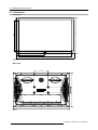


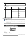

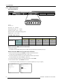
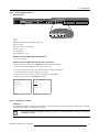
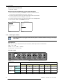

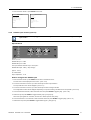


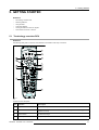


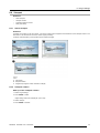
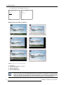

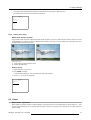


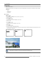
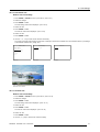
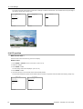
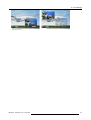


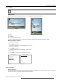


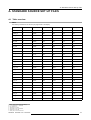


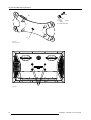


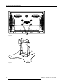


![Solaris LC40 [v04]](http://vs1.manualzilla.com/store/data/006347096_1-050cff7c0b4f91b9fb35d753454c0152-150x150.png)
![SLM R12+ Performer [v05]](http://vs1.manualzilla.com/store/data/006296879_1-50504fc86d9979ae79ec928acfe3e08c-150x150.png)