1
APEX-JLS User’s Manual
Revision 1.15.00
Copyright ©1998-2006 Newing-Hall, Inc.
2019 Monroe Street
Toledo, Ohio, 43624
NH Part # 2511000
Last Updated January 2006
Newing-Hall, Inc. makes every effort to update
and insure the manuals and documentation is
accurate. In continuing efforts to improve Newing-Hall’s
product line this manual is subject to change without notice.
Table of Contents
Chapter 1 - Installation Guide
1.1 Upon Receipt of Shipment
1.2 Assembly of Engraving Tables
1.3 Spindle Installation
1.4 Air Compressor Installation
1.6 Installing the AMC Controller
1.7 Installing the APEX Product Software
1.8 Spindle Operation - General
1.9 Diamond Spindle Operation
1.10 Rotary Spindle Operation
Chapter 2 - Overview
2.1 Getting Around
2.2 JLS Screen Areas
2.3 System Help
2.4 Creating A Simple Layout
2.5 Other Simple Job Controls
2.6 Setting up the Toolbox
2.7 Engraving the Work file
2.8 Creating a Manual Layout
2
Chapter 3 - Display Options
3.1 Scrolling the Draw Area
3.2 Zooming the Draw Area
3.3 Rulers & Guides
3.4 Maximizing the Available Draw Area
3.5 Preview
3.6 Unit Preferences
Chapter 4 - JLS Objects
4.1 Plates
4.2 Jobs
4.3 Frames
4.4 Lines
4.5 Elements
4.6 Symbol Libraries
4.7 Object Selection
4.8 Aligning Objects
Chapter 5 - Object Attributes
5.1 Setting An Object's Attributes
5.2 Attribute Dialog Box Controls
5.3 Standard Attributes
5.4 Using Standard Attributes
5.5 Job Attributes
5.6 Using Job Attributes
3
5.7 Frame Attributes
5.8 Using Frame Attributes
5.9 Line Attributes
5.10 Using Line Attributes
5.11 Graphic Attributes
5.12 Using Graphic Attributes
5.13 Character Attributes
5.14 Using Character Attributes
5.15 Attributes for Multiple Objects
5.16 Text Layout
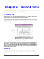
Chapter 6 - Text And Fonts
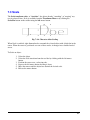
6.1 Entering Text
6.2 Fonts
6.3 Kerning
6.4 Importing Text
6.5 Importing TrueType™ Fonts
Chapter 7 - Object Transforms
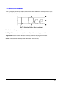
7.1 Selection Nodes
7.2 Move
7.3 Scale
7.4 Size
7.5 Rotate
7.6 Mirror
4
7.7 Slant
7.8 Duplicating Objects
7.9 Repeat
Chapter 8 - Tool Box
8.1 Tools and Cutting Specs Defined
8.2 Example Applications
8.3 Tools Changes
8.4 Toolbox Parameters
8.5 Assigning Cutting Specs To JLS Objects
8.6 Controlled Z-Axis Tools
8.7 Toolbox Default Settings
8.8 Suggested Feed Rates And Dwell Settings
8.9 Sample Tool/Cutting Spec Configurations
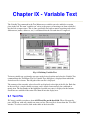
Chapter 9 - Variable Text
9.1 Text File
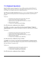
9.2 Starting Entry
9.3 New File Button
9.4 Edit File Button
9.5 Inc
9.6 Next
9.7 Using Variable Text
Chapter 10 - Serialization
10.1 Serial Field
5
10.2 Selection Range
10.3 Leading Zero Mode
10.4 Full Field
10.5 Using Serialization
10.6 Serialization Example
10.7 Re-using Serialized Work files
Chapter 11 - Simple Text Editor
11.1 Using the Simple Text Editor
11.2 Exiting the Simple Text Editor
11.3 Importing Text
11.4 Undo
11.5 Clipboard Operations
11.6 Justification
11.7 Changing the Display Font
11.8 Word Wrap
11.9 Text Blocking
Chapter 12 - Import/Export Graphics
12.1 Advantages of True Arcs
12.2 Advantages of HPGL
12.3 Import Graphic
12.4 Export Graphic
6
Chapter 13 - Dials & Scales
13.1 Composition
13.2 Dial Parameters
13.3 Scale Parameters
13.4 Graduations
13.5 Text
13.6 Cutting Specification
13.7 Direction
13.8 Making a Dial (Frame)
13.9 Making a Scale (Frame)
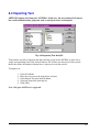
Chapter 14 - Columnizing
14.1 Making a Columized Frame
14.2 Advanced Columnizing
Chapter 15 - Clipboard
15.1 Manipulating Objects within JLS
15.2 Sharing Text with Other Applications
15.3 Loading Graphics from Other Applications
15.4 Cut
15.5 Copy
15.6 Paste
Chapter 16 - Machine Config/Setup
16.1 Machine Configuration
7
16.2 Machine Setup
16.3 Confirm Execution
Chapter 17 – Long Plate/Tall Plate
17.1 Overview
17.2 Engraving Direction and Positioning
17.3 Engraving a Plate
17.4 Measuring
Chapter 18 - Compatibility
18.1 EC Job File Conversion
18.2 Graphic/Logo Conversion
Chapter 19 - Font Editor
19.1 Using Existing Windows Fonts
19.2 Creating New Fonts
19.3 Editing Fonts
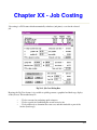
Chapter 20 - Job Costing
20.1 Costing Of Fonts
20.2 Costing Of Graphics
20.3 Costing Of Setup/Machine Time
20.4 Costing A Job
8
Appendix A - Glossary
Appendix B - System Hook-Up
Appendix C - Sample Exercises
Appendix D - Maintenance Procedures
Appendix E - Symbol Font Keys
Appendix F - APEX-JLS Fonts
Warranty
9
Chapter 1 - Installation
1.1 Upon Receipt of Shipment
Shipping Box
Check the shipping box for damage. If any damage is found, it is important, for insurance
purposes, to indicate this on the freight company's bill of lading before accepting shipment. Call
Newing-Hall's Customer Service at 1-800-521-2615 to report any damage.
Unpacking
Open shipping carton carefully and remove all boxes. DO NOT DAMAGE SHIPPING
CARTONS! Items returned to the factory for service must be shipped in their original containers,
and packed according to applicable instructions provided.
Check the packing list to see that all items have arrived. Call Customer Service if there is a
discrepancy.
10
1.2 Assembly of Engraving Tables
Model 240SE, 300, and 400 Engraving Tables
Remove the engraving table from the box and place it on a flat surface where it is to be installed,
leaving room for rear access.
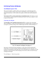
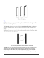
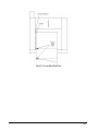
With wire cutters or a sharp knife cut the two large plastic straps that hold the bridge in place for
shipment (see fig. 1-2).
Fig. 1-2 Removal of Foam Shipping Block
Lift the rear of the engraving table slightly and remove the plastic straps.
Remove the foam block from between the bridge and the center cross member.
Table Plate Installation
Remove the four (4)-table plate springs and two 2-3/4" guide pins from the tool kit.
Place one table plate in the engraving table so that the two spring holes are facing you with the
table plate as far back as possible, against the center cross member (see fig. 1-3).
11
Fig. 1-3 Installation of Table Plates
Position the other table plate in front of the engraving table with the spring holes facing away
from you (see fig. 1-3).
Insert one spring into each spring hole, 2 per table plate and insert one pin into each spring hole
on the rear table plate (see fig. 1-3).
Lift the rear table plate slightly and align the front and rear table plates with the pins.
Push the front table plate toward the rear until it clears the inside of the front cross member,
lower it into the frame, and release it.
Dynagrip Table Installation without Pedestal
The Dynagrip table installs in the same manner as the table plates. Insert the top edge of the
Dynagrip table into the NH-300/400 Engraving Table, push it up against the center cross
member and carefully set it into place (see fig. 1-4).
12
Fig. 1-4 Installation of Dynagrip Table
Dynagrip Table Installation for NH-400 with Pedestal
The Dynagrip table installs by inserting the top edge of the table into the NH-400 Engraving
Table, pushing it up against the center cross member and carefully setting it into place.
Cam Installation
Remove the cam and cam lever knob from the tool kit and mount the cam assembly onto the
front cross member (see fig. 1-5).
Fig. 1-5 Cam Installation
13
NH-600 Engraving Table
Remove the T-slot table by inserting the threaded T-handle into the hole under the rubber
manifold cover, and lift carefully. (The hole is positioned at the front center of T-slot and
vacuum tables.) Position it near to the area where the engraving table is to be installed.
Remove the engraving table from the box and place it on a flat surface where it is to be installed,
leaving room for rear access.
Remove the foam block from between the bridge and the center cross member.
Standing in front of the engraving table, place the T-slot or vacuum table into the engraving table
as shown (see fig. 1-6).
14
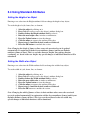
1.3 Spindle Installation
Setting the Spindle Travel
It
is best to keep the spindle positioned so that it runs with minimal actuation. This will minimize
dwell time required during engraving and improve overall speed of the engraving job. To do this:
1. Connect and power-up the controller (and air pump).
2. Press the Test Left Spindle button.
3. Lower or raise the bottom Z-Stroke/Height adjust knob until the nose cone of the
spindle touches the engraving material.
4. Release the Test Left Spindle button.
5. The spindle should raise approx. 1/8 in. If it rises more or less than 1/8 in., adjust
the upper Z-Stroke/Height adjust knob for desired actuation.
Setting the Spindle Pressure
The pressure of the spindle determines how quickly the spindle actuates, and how hard the
cutting tool is driven into the material. Insufficient pressure will result in poor/incomplete
engraving. Excessive pressure may result in nose rub. To set the desired spindle pressure:
1.
2.
3.
4.
Remove the cutting tool from the spindle.
Press the Test Left Spindle key on the controller.
Observe how hard the spindle moves downward.
Turn the airflow adjustment screw at the top of the spindle clockwise to reduce
spindle pressure, or counterclockwise to increase the pressure.
5. Continue to repeat steps 2-4 until a smooth actuation is achieved.
NH-300, 400, 600 Diamond Spindle Installations
Screw the needle valve assembly into the port of the quick exhaust valve marked "L" (see fig. 18). Do not over tighten.
15
Fig. 1-8 Conventional Needle Valve Assembly
Note: Do not attempt to alter the position of any other air fittings on the Spindle or damage
may result.
Locate the black T-slot on the front of the bridge assembly.
Be sure to hold the spindle barrel to prevent it from falling out of the spindle housing
Loosen the black knobs on the spindle so that the T-bolts stick out about 1/4" from the rear of the
spindle housing (see fig. 1-9).
Align the T-bolts with the left side of the center slot and slide the spindle to the right.
Position the spindle housing in the center of the T-slot aligning it with the location marks on the
top of the T-slot (see fig. 1-10).
Rotate the stainless steel spindle barrel so that the needle valve extends directly toward the front
of the engraving table (see fig. 1-9).
Position the spindle barrel so that the diamond stylus is approximately 1/2" above the table
plates. Tighten the black knobs on the front of the spindle.
16
Fig. 1-9 Mounting a Conventional Diamond Spindle
Attach the left air hose by pushing it into the fitting on the needle valve.
Fig. 1-10 Spindle Location Marks
NH-300, 400, 600 Rotary Spindle Installations
Screw the needle valve assembly into the port of the quick exhaust valve marked "L" (see fig. 111). Do not over tighten.
NOTE: Do not attempt to alter the position of any other air fittings on the Spindle or damage
will result.
17
Fig. 1-11 Conventional Needle Valve Assembly
Locate the black T-slot on the front of the bridge assembly.
Loosen the black knobs on the spindle so that the T-bolts stick out about 1/4" from the
rear of the spindle housing.
Align the T-bolts with the right side of the center slot and slide the spindle to the left as
shown (see fig. 1-12).
Fig. 1-12 Mounting the Conventional Rotary Spindle
Position the spindle housing in the center of the T-slot aligning it with the location marks on the
top of the T-slot (see fig. 1-13).
18
Tighten the black knobs on the front of the spindle.
Attach the right air hose fitting by pushing it into the fitting on the needle.
Fig. 1-13 Spindle Location Marks
Rotary Drive Installation
Remove the attached screw attached to the riser stud. Slide the rotary drive riser stud into the
right rear cross member. Secure the stud under the rear cross member with the supplied screw.
|
Fig. 1-14 Conventional Rotary Drive
Place yoke into the slot under the spindle pulley and wrap belt around the spindle pulley as
shown (see fig. 1-15).
19
Fig. 1-15 Yoke Installation
20
1.4 Air Compressor Installation
Engraving Table without Pedestal
Remove the air compressor from its carton.
Screw the air regulator assembly into the front of the air compressor (see fig. 1-16).
Fig. 1-16 Air Regulator Assembly
Plug the electrical line into the foot switch and the foot switch into a wall outlet.
While facing the rear of the engraving table connect the yellow-coiled hose to the quickdisconnect fitting on the left.
Pull back on the outer ring while making the connection and then release (see fig 1-17).
Caution: Opposite the regulator is an inlet opening. Before operation, remove any plug that
may have been installed in this opening.
21
Fig. 1-17 Air Compressor Connection
Engraving Table with Pedestal
Remove the air compressor from its carton.
Plug the electrical line into the outlet on the rear of the pedestal marked "Air Compressor".
While facing the rear of the engraving table connect the yellow-coiled hose to the quickdisconnect fitting on the left of the pedestal. Pull back on outer ring while making the
connection, then release (see fig. 1-18).
Fig. 1-18 Air Compressor Connection (Pedestal)
22
Air Compressor Test
Engraving Table without Pedestal
Press the foot switch to start the air compressor.
Turn the knob on top of the assembly clockwise to increase the pressure and counterclockwise to
decrease pressure.
Adjust the pressure to 15 psi.
Note: Excessive air compressor vibration may be caused by pressure in the line. This may be
corrected by actuation of the spindle using the test spindle button on the front of the controller.
Engraving Table with Pedestal
Plug the pedestal power cord into an electrical outlet.
To start the air compressor turn on the switch marked "Air Compressor" located on the front.
Turn the air regulator knob clockwise to increase pressure and counterclockwise to decrease
pressure.
Adjust the air regulator until the pressure gauge reads 15 psi.
23
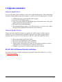
1.6 Installing the APEX-AMC/HPGL Controller
NH-300 and NH-400 Engraving Tables without Pedestal
Remove the Apex AMC/HPGL controller from its carton and carefully place the controller
upside down, facing you on a stable protected surface near the engraving table.
Place the controller stand upside down onto the bottom of the controller with the controller
supports curving to the back of the controller. (See fig 1-22).
Fig. 1-22 Assembly of the Controller and Stand
Align the mounting holes in the stand with the four (4) tapped holes in the bottom of the
controller and secure the controller to the stand using the four (4) 10-32 BHCS (see fig 1-22).
Install the controller and stand to the NH Engraving Table by pressing in the tabs on the
controller bracket and slide it into the horizontal mounting holes. Continue to slide the controller
bracket in until the tabs on the bracket lock into place. (See figure 1-23)
Note: Do not adjust the mounting blocks they are set at the factory.
24
Fig. 1-23 Controller and Stand Installation
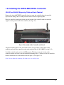
NH-400 and NH-600 Engraving Table with Pedestal
Remove the Apex AMC/HPGL controller from its carton and carefully place the controller
upside down, facing you on a stable protected surface near the engraving table.
Locate the controller bracket and align the holes in the bracket with the four (4) tapped holes on
the bottom of the controller. Secure the bracket to the controller making sure that the angle of the
bracket post is toward the rear of the controller (see fig 1-24).
Assemble the controller arm to the mounting post located to the left rear of the pedestal and
secure it with the lever knob. Attach the controller to the arm and secure it with the remaining
lever knob (see fig 1-24).
Fig. 1-24 Controller and Arm Installation
25
Cable Connections
Refer to Appendix B for a cable hookup diagram. Be sure that the AC power to the AMC or
HPGL controller and the host computer is OFF before connecting any cables. Connect the
cables as follows:
1. Connect the 9-pin RS232 cable to the AMC 9-pin serial port. This is located in the
middle of the rear panel of the AMC. The HPGL 9-pin serial port is located in the
right rear panel of the HPGL.
2. Connect the remaining end of the 9-pin RS232 cable to the computer's serial port
(COM 1 or COM2).
3. Connect end of the 25-pin Motor Driver cable labeled "APEX MOTOR DRIVER
PORT" to the AMC controller. This is located on the left side of the rear panel
(looking from behind). The HPGL motor driver port is located in the right rear
panel of the HPGL.
4. Connect the 4-way end of the rotary motor power cord to the AMC rotary motor
power connector. This is located on the right side of the rear panel. The HPGL 4way connector is located in the left rear of the HPGL. Systems that have been
upgraded from NH-series systems, which have a Bodine motor, require an adaptor
cable (supplied).
5. Connect the standard AC power cord to the AMC main power connector on the
right side of the AMC rear panel. The HPGL main power connector is located on
the left side of the HPGL rear panel. Connect the remaining end of the power
cable to a standard wall outlet.
6. Connect the serial mouse, if applicable (COM1 or COM2).
NOTE: IF INSTALLING HPGL AND ETHERNET PLEASE SEE THE HPGL MANUAL.
26
Controller Test
To verify that the controller is in working order:
AMC:
1. Turn on the POWER switch on the rear of the AMC. The AMC will initiate its
power-on self-test and fan on the side of the controller will begin operating once
the drives are turned on. After the test, the menu screen on the front of the
controller will read:
2. Press the "Drives On" key to enable motion on the table.
3. Press the jog (red arrow) keys on the left side of the AMC front panel. The bridge
should move accordingly. If there is no movement check to see that the drives are
ON, and also check the cable connections.
4. To test the rotary spindle motor, press the Datum <F1> key, followed by the
Execute <F1> key to display Start/Go to Home.
5. Press the Spindle key. Immediately press the + key and hold it down. The spindle
motor should turn on after a moment, and the menu screen should show the
percent spindle speed increasing. The - key will decrease the speed. If the rotary
motor does not turn on, check to see that the drives are ON, and also check the
rotary motor power cable connection.
HPGL
1. Turn on the POWER switch on the rear of the HPGL controller. The HPGL
controller will initiate its power-on self-test.
2. Press the “Drives On” key on the front panel.
3. Press the jog keys on the left side of the HPGL front panel. The bridge should move
accordingly. If there is no movement check to see that the drives are ON, and also
check the cable connections.
4. To test the rotary spindle motor, press the “SPDL” spindle key. Adjust the rotary
motor speed control located on the right side of the front panel.
27
1.7 Installing the APEX Product Software
The APEX Product Software is distributed on a CD-ROM. It has an automated installation
process that makes installation fast and easy.
1. Start the host computer.
2. Insert the CD-ROM in the CD drive. The CD-Browser should start automatically.
If the browser does not start navigate to the CD-ROM drive and double click on
CDStartup.exe.
3. A number of options are available depending on the version of the CD-Browser
including the option to install APEX Product Software.
4. To install APEX Product Software click the APEX Product Software button.
APEX Product Software will auto configure the software components that are
derived from setup.
5. Once the installation of APEX Product Software starts answer the questions
presented by the installation wizard. Once the installation wizard collects enough
information the files will be copied to the computer then configured.
NOTE: IF INSTALLING HPGL AND ETHERNET PLEASE SEE THE HPGL MANUAL.
28
1.8 Spindle Operation - General
Left/Right Spindle Keys
The Left and Right Spindle keys are located to the left of the large emergency stop button on the
front panel of the AMC. The HPGL keys are located in the center. These keys control manual
actuation (up and down movement) of the spindles.
AMC
To use these functions, turn on the air pump and adjust the air pressure and flow as directed
below. Then press the Left Spindle or Right Spindle key. The corresponding spindle will extend
to its "down" position.
When these keys are released the corresponding spindle returns to its "up" position.
HPGL
To use these functions, turn on the air pump and adjust the air pressure and flow as directed
below: Then press the “TEST SOL” key. Next press the “L” or “R”. Pressing the “L” or “R”
key once causes the spindle to extend to the down position. To retract the spindles press the ”L”
or “R”. When finished press the “TEST SOL” key again to exit the solenoid test.
Air Pressure
Air pressure determines the downward force of the spindle on the engraving material.
Turn the regulator valve on the air pump clockwise to increase the spindle's downward force,
counterclockwise to decrease it.
Air Flow
Airflow controls the speed of the downward travel. It does not change the pressure being applied
to the engraving material.
To adjust the airflow, press the corresponding Left/Right Spindle key while turning the needle
valve on the spindle assembly. Turn the valve clockwise to reduce airflow and counter-clockwise
to increase it.
By adjusting the needle valve, the downward travel speed can be controlled to prevent damage to
the cutting tool while achieving optimum speed down to the work material.
29
1.9 Diamond Spindle Operation
Ping Marks
Proper adjustment of the airflow eliminates diamond spindle "ping marks" on the engraving
material. The speed of the downward travel can leave a small indentation in the plate, known as a
ping mark, which is undesirable. If this cannot be corrected by adjusting the airflow you may
have to reduce the air pressure.
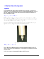
Replacing a Diamond Graver
The Diamond Graver is the diamond tip insert that fits into the end of the diamond spindle on
Models 300, 400, and 600. The diamond is subject to wear and occasionally must be replaced in
order to maintain a high quality cut. To replace a Diamond Graver, remove the setscrew with a
1/16" Allen Wrench and remove the old Graver (see fig. 1-25).
Insert the new Diamond Graver with the flat side towards the setscrew hole so that when you
tighten the setscrew it will press into that flat side of the Diamond Graver.
Fig. 1-25 Diamond Graver Installation
Multiple Diamond Spindles
Models 300, 400, and 600 allow simultaneous engraving with multiple diamond spindles. To
engrave several identical plates simultaneously, set each spindle at its designated home position
and set the airflow.
In JLS, select the proper tool setup in the Tool Box for "BOTH" spindles.
30
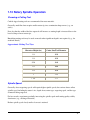
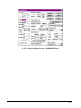
1.10 Rotary Spindle Operation
Choosing a Cutting Tool
Carbide-tipped cutting tools are recommended for most materials.
Generally, multi-line fonts require smaller cutter-tip sizes to maintain sharp corners (e.g., on
serifs).
Note also that the width of the line engraved will increase as cutting depth is increased due to the
beveled shape of most cutter tips.
Burnishing cutting tools may be used on metals when significant depth is not required (e.g., for
anodized metals).
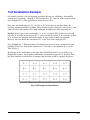
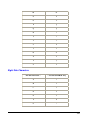
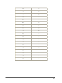
Approximate Cutting Tool Sizes
Character Height (in.)
Cutter Size/Tool Diameter
1/8
.020
1/4
.030
5/16
.040
1/2
.060
3/4
.090
1
.125
1 1/4
.171
Spindle Speed
Generally, faster engraving speeds will require higher spindle speeds, but various factors affect
spindle speed, including the cutter's size, depth of cut, cutter type, engraving speed, and the type
of material being engraved.
For best results, experiment, gradually increasing the spindle speed until cutting quality visibly
deteriorates (e.g., melting of material).
Reduce spindle speed slowly until a clean cut is attained.
31
Dual Synchronized Rotary Spindles
Models 300, 400, and 600 allow mounding of dual rotating spindles. To engrave two identical
plates simultaneously, set each spindle at its designated home position and set the airflow for
each spindle.
In JLS, select the proper tool setup in the Tool Box for "BOTH" spindles.
Dual Independent Rotary Spindles
Dual rotary spindles may also be used independently for engraving a single plate with two
different cutting tools (e.g., tool diameters).
For this operation it is necessary to mount the spindles adjacent to each another so that they
touch. This sets the tools 2.0 inches apart.
Be sure that the correct "home" spindle specified in the JLS software is properly positioned
before engraving.
Rotary Engraving with a Nose
Remove the rotary spindle from the machine.
Screw the nose assembly onto micrometer sleeve (see fig. 1-26).
Fig. 1-26 Nose Assembly Installation
Rotate spindle to make sure nose has seated properly in micrometer sleeve. (No threads should
be visible.)
32
WARNING! Failure to seat nose assembly may result in damage to cutting tool and
unsatisfactory engraving.
Remount the rotary spindle onto the machine (see page 1-13).
Insert Cutting Tool and Set Depth
Loosen the setscrew in the brass cutter head with the supplied small, L-shaped cutter head
wrench (see fig. 1-27).
Fig. 1-27 Cutting Tool Assembly
Slide the brass cutter head to the midsection of the cutting tool. Lightly tighten the setscrew.
Insert cutting tool assembly into the hole at the top of the spindle pulley and turn brass cutter
head counter-clockwise to tighten (see fig. 1.28)
33
Fig. 1-28 Installation of Cutting Tool Assembly
The reverse thread prevents loosening during engraving.
Zeroing the Cutting Tool
Set the micrometer sleeve so the indicator points to zero (see fig. 1-29).
34
Fig. 1-29 Adjusting the Micrometer Sleeve
Place some scrap material on the engraving table beneath the spindle.
While gripping the top of the cutting tool shank, loosen the setscrew in the brass cutter head to
adjust the cutting tool.
Push down on the spindle pulley (to lower the spindle barrel) until the nose touches the flat
surface of the material.
While holding the spindle in the down position, push the cutting tool shaft lightly so that the tip
of the cutter touches the engraving material.
Tighten the setscrew in the brass cutter head and release the spindle pulley. This is known as
"zeroing" the cutting tool.
Setting the Depth
Rotate the micrometer sleeve counterclockwise to set the depth of cut. One click of the
micrometer sleeve is equal to 0.001" in depth. The type of engraving material and character size
35
determines the proper setting. See the previous chart of approximate cutting tool sizes for a
starting point.
Always use the nose when engraving on plastic to control depth accurately.
Rotary Engraving without a Nose
Insert Cutter and Set Depth
This method may be appropriate for cutting deeply into metals or where nose rub is a detriment.
Press down on the spindle pulley to lower the spindle.
Rotate the alternate depth micrometer (ADM) clockwise until the bottom of the micrometer
sleeve is 1/4" to 1/2" above material when pressing down on the spindle pulley (see fig. 1-30).
Fig.
1-30 Alternate Depth Micrometer Setup
Release the spindle pulley and turn the ADM to zero.
Insert the cutter into the hole at the top of the spindle pulley and turn it counter-clockwise to
tighten (see fig. 1-28).
Place some scrap engraving material on the table.
36
Loosen the setscrew in the brass cutter head.
Press down on the spindle pulley until the stop plate hits the stop nut and hold, and then press the
cutter down until the tip touches the material.
Tighten the setscrew on the cutter head and release the spindle pulley.
Rotate the ADM counter-clockwise until desired depth is reached. Each mark is equal to 0.001"
in depth.
Note: If the engraving cut is shallow on one side, shim the item with paper, thin plastic or
shim material on the shallow side.
If a greater depth is desired the nose assembly may be removed. However, this setup is not
recommended, and requires that the chip removal system be removed.
To remove the nose assembly, unscrew the retaining nut, remove the nose, and finally the chip
removal system. Do not reinstall the retaining nut.
Follow the procedure listed above for inserting the cutting tool and establishing the depth of cut.
Up-Travel Stop
As the spindle retracts upon completion of a character segment, the up-travel stop will limit the
up travel of the quill assembly (see fig. 1-31).
Fig. 1-31 Up-Travel Stop
37
For maximum efficiency and speed, the up-travel stop should be set so that in the "up" position
the tip of the cutter is 1/16" to 1/8" above the material.
This will allow a quicker dwell setting while still completing each character segment.
38
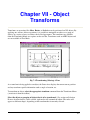
Chapter II - Overview
This section introduces the JLS display and user interface, and describes the basic principles for
operating the JLS program. Detailed descriptions of the commands, as well as instructions for
creating and manipulating items on the plate, are all provided in later sections of this manual.
2.1 Getting Around
Using the Mouse and Cursor
APEX-JLS provides an on-screen cursor which is moved around the screen by means of a mouse
or a digitizer tablet. The cursor changes appearance over certain screen areas to indicate a change
in context. For example, an arrow cursor may change to a text I-beam when positioned over a
text to signify that text-editing operations are available at that point.
The cursor may also change appearance to indicate a change in function, for example, a "hand"
with its index finger outstretched indicates that the user may "press" a button on the tool bar by
clicking on its icon.
Using the Keyboard
In addition to the mouse, the keyboard is also supported. It is possible to select and execute menu
items using the keyboard, but full interactive operation of APEX-JLS requires a mouse or
digitizer.
Where textual or precise information is required, JLS supports keyboard input into standard entry
forms, including dialog boxes, list boxes, etc. Keyboard input is used as the primary means of
entering characters for text.
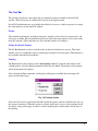
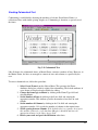
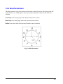
Using the Tool Bar
The Tool Bar is located at the top of the Draw Area and consists of a series of pushbuttons for
quick selection of certain commonly used functions and modes.
Fig. 2-1 JLS Tool Bar
Each JLS function/mode is accessed by a corresponding pushbutton and represented pictorially
by an icon positioned directly on top of the pushbutton. The buttons are grouped into sets by
colors and consist of:
39
Screen modes (white) - The screen modes on the left side of the
tool bar comprise the first group of buttons. These buttons allow
you to determine the position and magnification factors for
viewing the plate.
Edit modes (green) - The edit mode buttons allow you to select
and add objects of a particular type and also to edit text. The
currently selected mode enables and/or disables certain functions
of APEX-JLS.
Edit levels (yellow) - The edit level buttons allow you to select the
type or level of objects you are dealing with. The different edit
levels are job, frame, line and element. There is no plate level, as
the only way to alter the plate is to resize it using the plate setup
dialog box.
Transforms (blue) - The transforms are located on the far right
side of the tool bar. These buttons include the main transform
functions, such as rotate, move and resize. The transforms are only
available in select mode and operate exclusively on any selected
objects.
Note: A complete diagram of the tool bar is included at the front of this manual on a handy
reference card.
Choosing the `Show Tool Bar’ command in the Options menu can disable the tool bar. This is a
toggle, and alternately turns the tool bar on or off each time it is selected.
Using Accelerator Keys
Another ease-of-use feature is the existence of `accelerator' keys. These are `hot keys' that allow
immediate execution of certain commands without having to pull down menus.
For example, opening a work file is normally done via the Open command from the File Menu.
The accelerator key combination for this is CTRL-O, and is displayed immediately to the right
of the Open command. Hold the Ctrl key down and press the O key to access the Open
command.
40
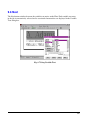
2.2 JLS Screen Areas
To start JLS, double-click on the JLS icon from the APEX program group. The software will
present its sign-on screen and then display the main work area (the current program version
appears on the status bar).
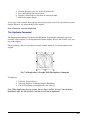
The main screen of JLS consists of four basic components:
Draw Area - Plate/text display
Menu Bar - Menu of commands
Status Bar - Instructions for current process
Tool Bar - Collection of buttons, switches
Fig. 2-2 APEX-JLS Main Screen
41
Draw Area
The Draw Area is the large graphical area in the center of the JLS main window. It contains the
graphical view of the plate and allows for interactive editing of the work file.
Menu Bar
The Menu Bar extends across the top of the main window and contains the names of the menus
available during the editing process (i.e. File, Edit, & Help). By clicking on the menu names, the
appropriate menus are displayed along with various options and commands.
Status Bar
The Status Bar is located at the bottom of the screen and provides the user with English-language
instructions on what is happening at the current time and what to do next. Updates after
transformations, directions on what to type/do during specific functions, size and positioning
information, etc. all appear on the status bar during various operations.
Tool Bar
The Tool Bar is located immediately beneath the Menu Bar and contains pushbuttons that
represent options or commands in the JLS menus. By merely pressing one of the pushbuttons, an
operation is completed - quickly and easily.
42
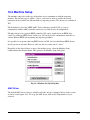
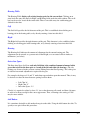
2.3 System Help
JLS provides a powerful context-sensitive help facility. To access this facility, select Help from
the main menu.
Some of the ways to obtain help are:
Choose the Help Menu. The buttons near the top of the Help window allow the user to access
help in the most convenient manner for a specific task:
•
•
•
•
•
•
Contents- Displays a list of topics
Search- Search for a specific topic
Back- View the previous topic
History- Displays topics in the order
>> - Next page in Help
<< - Previous page in Help
Press F1 at any time. If the current operation is found in the help system, Help will be opened at
that point to give context-sensitive help on the current operation. Otherwise, Help may be opened
at the main help index for further action.
Select the Help key from a dialog box that has one. Pressing the Help key will display
information on procedures for the current dialog box or related function.
Use Context Sensitive Help. This is accomplished by selecting the 'question mark' button at the
extreme right portion of the tool bar.
After pressing the button, the cursor changes to a help arrow. Place the arrow on the area of the
screen or the item for which help is desired. Click the left mouse button again and help will be
given on the item or the contents of the screen immediately beneath the cursor.
43
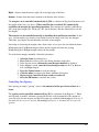
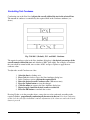
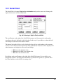
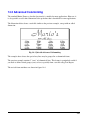
2.4 Creating a Simple Layout
The Simple Layout consists of one Job and one Frame (to establish margins) that contains a
number of text lines. The Job and Frame are exactly the same dimensions as the Plate.
To do a Simple Layout:
1. Select the New command from the File Menu.
2. Enter the desired Plate size.
3. Press the Simple Job button. The Job will automatically be
created to occupy the entire Plate.
4. Select the desired font, if necessary.
5. Enter the desired text in the Text window. The appropriate
number of lines will be created automatically to match the number
of text lines entered from the keyboard.
6. Press OK to create the layout. It is that simple.
Fig. 2-3 Creating A Simple Job
Once the job is created, it can be modified in any way in the main program.
44
Step 1 - Selecting the New Command
The first step when creating any new work file is to select the New command from the File
Menu. To do this, move the cursor onto the main menu bar so that it is positioned directly over
"File" and click the mouse. This displays the File Menu, which contains the new command.
Move the cursor over "New" and click the mouse to activate the new command. The Plate Setup
dialog box is displayed, which allows you to configure the plate dimensions and other aspects of
the plate.
Fig. 2-4 the Plate Setup Dialog Box
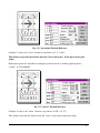
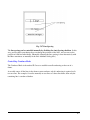
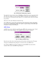
Step 2 - Entering the Plate Size
To enter the plate height, double-click in the Height field and enter the height, in inches (or
millimeters) from the keyboard.
To enter the plate width, double-click in the Width field and enter the width, in inches (or
millimeters) from the keyboard.
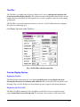
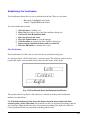
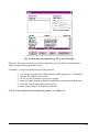
Step 3 - Selecting the Plate Layout Method
Press the Simple Job button to initiate a simple layout. One job and one frame are automatically
created for you, and are exactly the same size as the plate. The Single Frame dialog box is
displayed, which allows you to configure the text in the new frame.
45
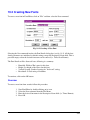
Fig. 2-5 the Simple Job Dialog Box
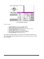
Step 4 - Selecting the Desired Font
To select a font, click the mouse in the Font list box. Use the scroll bar or arrow keys to review
the list of available fonts.
Click on the desired font name to select that font. Example text in the selected font is displayed
in the Preview area to the right of the Font list box
Step 5 - Entering the Text
To enter text, click in the Text box in the middle of the Single Frame dialog box. Enter the
desired text from the keyboard. To advance to the next line, press the Enter key.
Step 6 - Clicking OK
To finish the setup procedure, click on the OK button. Each text line in the Text box will be
automatically inserted into the frame.
The final plate is displayed in the Draw Area for you to examine (or edit further if desired).
46
2.5 Other Simple Job Controls
Controlling the Current Line
The Line controls determine which text line is being displayed or edited during text entry.
Checking the Count Lines checkbox instructs JLS to automatically count the lines as they are
entered (default). Every time the user presses the [Enter] key a new line is created. JLS
automatically keeps track of the total number of lines. The Number of Lines display indicates
the total number of lines in the simple job.
If the Count Lines checkbox is not checked, then the Number Of Lines field is active, and you
may enter the desired number of (blank) lines for the job without having to enter any text. Text
may then be entered directly from the JLS main screen, after the simple job is created.
The Line field indicates the current line by a line number. Lines are numbered from the top,
starting with line 1. Use the arrow buttons to the right of the line number to change to the next or
previous text line. To change to a specific line, simply enter the desired line number into this
field. The text caret is automatically repositioned in the Text window.
The Set Line from Caret button sets the line number based on the current position of the text
caret in the Text window. To determine which line number corresponds with a line of text;
click on the text to position the text caret, and then press the Set Line from Caret button.
Controlling Line Heights
Line heights may be manipulated from within the Simple Job dialog box. If Auto Heights is
checked (default), then JLS automatically controls the heights based on the Line Height
Proportions for each line. If Auto Heights is not checked, then the line height for each line can
be entered specifically.
Auto Heights Enabled
In this case, JLS will automatically set the heights of the lines as follows:
•
•
First, JLS reviews the Line Height Proportions values for all the
lines and scales them accordingly. For example, if the proportions
for a three-line job were 20, 40, and 80, then the height of Line 3
would be four times the height of Line 1, and twice the height of
Line 2.
Next, the combined height of all the lines is set to a percentage of
the available height of the job (less margins). The Engrave% field
establishes this. For example, and Engrave% of 55% reserves
about 55% of the job height (less margins) for text lines, and 45%
for interline spacing.
47
To set the Line Height Proportions, set the desired line number in the Line field, and then enter
the corresponding proportion value in the Line Height Proportion field. Increasing the Line
Height Proportions for a given line decreases the heights of the other lines, and vice versa. Note:
The actual numbers are not important – only their relation to each other. For example, the
proportions mentioned above would generate the same result as (2, 4, and 8) or (100,200,400),
etc.
To set the Engrave%, enter the desired value in the Engrave% field. Increasing the Engrave%
increases the heights of all lines and decreases the interline spacing. Likewise, decreasing the
Engrave% field decreases the heights of all lines and increases interline spacing.
Auto Heights Disabled
In this case, it is up to the user to set the heights of the lines specifically. To do this, set the
desired line number in the Line field, and then enter the corresponding line height value (in
inches or millimeters) in the Actual Height field. If Auto Heights is disabled, the Layout
command will have no effect on the line heights.
Controlling Margins
"Margins" refer to the white space allocated as a border around the perimeter of the job. If the
Auto Margins checkbox is checked (default), the margins are controlled automatically by
JLS as a function of the plate dimensions and the heights of the lines. JLS sets the margins to
provide the most visually appealing result. Auto margins are initially established at 20% of the
job height (10% top and bottom) and then adjusted based on the line heights.
The margins can be set manually by disabling the Auto Margins checkbox. If Auto
Margins is disabled, JLS will not allocate margins, and the Layout command will have no
effect on margins. Setting the margins manually is discussed further in Chapter 5.
Controlling Spacing
"Spacing" refers to the interline spacing of text lines. If the Auto Spacing checkbox is checked
(default), the interline spacing is controlled automatically by JLS as a function of the line
heights and the margins. Recall that increasing the Engrave% decreases the interline spacing, and
decreasing the Engrave% increases the interline spacing.
The spacing can be set manually by disabling the Auto Spacing checkbox. If Auto Spacing is
disabled, JLS will not adjust interline spacing as a result of the Layout command. Setting the
spacing manually is discussed further in Chapter 5.
Controlling Text Justification
Justification affects the way text is positioned (horizontally) along the line. There are three
options:
48
•
•
•
Left- aligned with the left margin.
Center- aligned with the center of the job.
Right- aligned with the right margin.
To set the justification, click on the desired option button. The text in the Text window will be
re-positioned accordingly. All text in the simple job is justified the same.
49
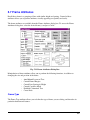
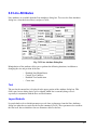
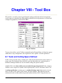
2.6 Setting up the Toolbox
JLS provides a versatile utility for specifying the cutting parameters for a given work file. These
parameters are located and configured, appropriately, in the JLS Tool Box. The following text
discusses toolbox settings for the simple work file created in the previous section.
To access the Tool Box, click on "Execute" to display the Execute Menu, and then click on
"Tool Box" to display the JLS Tool Box.
NOTE: The only fields the HPGL controller recognizes in the toolbox are Feed Rate, Tool
attributes and Path.
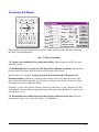
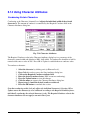
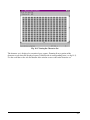
Fig. 2-6 The JLS Tool Box
A tool, in JLS, is a physical device, which scores or marks engraving material. It has a length, a
diameter, and is assigned to a spindle on the engraving system.
A cutting specification is a method of using a tool, which consists of a tool index (see above)
and various speeds, dwells, and other attributes.
Establishing the Proper Cutting Specification
The Cutting Spec field contains the index of the current cutting specification and is used as the
main index into the toolbox. The default cutting attribute is 1 for everything in the work file, so
values entered for Cutting Spec 1 will apply to everything that is engraved.
50
Setting the Feed Rate
The Feed Rate field contains a value from 0% to 100% that describes the maximum possible
speed during the machining cycle. Leave this at the default setting for acceptable results.
Note: Diamond-drag work files may be more efficient if the feed rate is set to 90% or more.
Setting the Spindle RPM
The Spindle RPM field contains a value from 0% to 100% that describes the maximum rotational
speed to use during the machining cycle. Set this to 0% for diamond-drag or 70% for acceptable
results using a rotary spindle.
Setting the Dwell Down
The Dwell Down field specifies the amount of time to wait, in seconds, after a tool-down
operation, before starting normal motion (pneumatic Z-axis only). Set this to 0.2 seconds for
diamond drag or 0.25 seconds for rotary engraving.
Setting the Dwell Up
The Dwell Up field specifies the amount of time to wait, in seconds, prior to a tool-up operation
before starting normal motion (pneumatic Z-axis only). Set this to 0.1 seconds for diamond drag
or 0.25 seconds for rotary engraving.
Additional Settings for Controlled Z-Axis
Setting the Number of Passes
The Number Of Passes refers to the number of times that the work file will be engraved. Each
pass penetrates the engraving material an equal amount until the total depth is achieved (see
below). For example, to cut to a depth of 0.100" in 5 passes means that each successive pass will
penetrate 0.020".
Setting the Depth
The Depth field refers to the depth of cut (see above). The depth varies with each application.
Setting the Z Clearance
Z Clearance is the distance between the point of the tool and the surface of the material during
tool-up motion. The clearance should be limited to the minimum distance required to clear the
tool safely from the material surface, jigs, etc. This will reduce the amount of time spent
retracting and replacing the tool.
51
Setting the Speed Down
Speed Down is the down feed rate for the Z-axis. This should be sufficiently fast to minimize job
time, but slow enough to provide adequate time for the tool to cut down into the material.
Setting the Speed Up
Speed Up is the up feed rate for the Z-axis. This should be set to the maximum speed (100%) to
minimize job time.
Establishing the Proper Tool Attributes
The Tool field contains the index of the tool assigned to the current cutting specification. Up to
eight different tools can be defined. The attributes of the tool are defined in the Tool Attributes
section.
Setting the Diameter
The tool diameter is the diameter of the tool at the surface of the material during machining. Set
this to 0.0 for diamond-drag or the proper diameter (0.020) for rotary engraving.
Setting the Spindle ID
The Spindle ID field specifies the spindle (Left, Right, or Both) in which the tool will be
mounted. Set this to Left.
For now, ignore the Path options. This will be covered later in this manual. Press OK to finish
the toolbox setup.
52
2.7 Engraving the Work File
To engrave the work file, select the Execute Menu and then click on the Machine command. A
summary of the current machining parameters is displayed, including options to control the
engraving process.
•
•
•
•
•
•
•
•
Remote Start- Allows engraving to be started from JLS.
Reload Fonts- Reloads fonts even if they exist in AMC.
Reload Symbols- Reloads symbols even if they exist in AMC.
Preload Fonts- Loads ALL fonts BEFORE engraving.
Preload Symbols- Loads ALL symbols BEFORE engraving.
Override Spindle- Allow spindle speed override at AMC.
Override Dwell- Allow dwell override at AMC.
Override feed rate- Allow feed rate override at AMC
Fig. 2-7 Machining Parameters
Once these options are configured as desired, press OK to send the work file to the AMC.
Once the work file is resident in AMC:
1.
2.
3.
4.
Press the Datum <F1> soft key.
Press the Execute <F1> soft key.
Jog the tool into its HOME position.
Jog the tool down to the material surface and digitize the surface position using
the Dig <F2> soft key (controlled Z-axis systems only).
5. Press the Start <F1> soft key.
If this is the first work file of the day, you may be prompted to:
53
Insert Tool 1 into the Left Spindle
Verify that you have the desired tool in the Left Spindle and press <F1> to begin engraving.
Note: The Machine Execute dialog box does not appear if the Confirm Execution checkbox is
not checked in the machine set up. See Chapter 16 for details.
Note 2: The HPGL Machine Execute differs than that of the AMC.
54
2.8 Creating a Manual Layout
JLS can be used to create an unlimited variety of manual layouts; however, they all follow a
general pattern. That is, a primary object is created, followed by lower-level objects. This
pattern, outlined below, constitutes the general method of creating a JLS plate definition by
manually.
1. Create the Plate using the New command from the File Menu. This must be
done first.
2. Create a Job on the plate. A job may occupy the entire plate or only a portion of
it. (Several different jobs may be defined on the plate, each with a different size,
position, orientation, etc. However, only one job is active in JLS at a given time.)
3. Create Frames, Lines (independent), and Elements (the job's child objects).
These may be created in any order, but frames must be created before creating
any lines that are part of those frames.
4. Modify the above objects and add Text (characters) to the lines. This can be
done any time a line has been created.
This general procedure is used to create a job regardless of the type of job or the specific method
of creation. Some of the above operations are performed automatically by JLS in certain cases.
Single Job Layout
This method is the best method for setting up a standard plate that has text and graphics or a
complex text layout.
The Single Job button creates the Plate and automatically creates a single job on top of it. The
job is exactly the same size as the Plate and is positioned precisely over the Plate, just like the
Simple Job option above. Single Job, however, does not define any other objects (i.e. frames,
lines). The user is now free to manually create any other JLS objects as desired.
55
Chapter III - Display Options
This chapter discusses methods of displaying your work in JLS. The discussion includes the
powerful Preview feature, which shows the plate, as it will be engraved; with different colors
depicting different tools or cutting methods.
3.1 Scrolling the Draw Area
The Draw Area is a window, or "view port" through which you can view the plate. It may be
desired to move the view port around to show different parts of the plate at the current
magnification setting. This movement is generally known as "panning" or scrolling. Scrolling is
done via scroll bars attached to the bottom and right sides of the JLS window.
Fig. 3-1 Scroll Bars in JLS
To scroll the Draw Area, place the cursor over a scroll bar arrow and click. The Draw Area
will be scrolled in the direction of the arrow. The slider box moves accordingly. When the slider
box is positioned at the extreme end of a scroll bar, the Draw Area cannot be scrolled further in
that direction.
56
Alternately, it is possible to directly position the plate by dragging the slider box in the
desired direction and then releasing the mouse button. Place the cursor over the desired slider
box, depress the left mouse button, drag the mouse as desired, and then release the mouse button.
57
3.2 Zooming the Draw Area
The Draw Area may be magnified, or "zoomed", as desired to change the amount of the plate
displayed within the Draw Area. The following zoom options are available from the View Menu,
but are more commonly accessed via the JLS Tool Bar.
Zoom Full
The Zoom Full command is used to display the entire plate in the main window. To Zoom Full,
simply click on the left-most pushbutton. (The tool bar icon for this operation is a white square.)
Fig. 3-2 Zooming In
Zoom In
The Zoom In command allows you to select an area of the plate to be displayed in more
detail. This area will be magnified to completely occupy the Draw Area window.
To zoom-in on a specific area, select the Zoom In command with the left mouse button. (The
tool bar icon for this operation is a magnifying glass.) The cursor changes to a large magnifying
glass to signify that the current operation is zoom in. Then move the cursor to the upper left
corner of the area to be zoomed. Depress the left mouse button and hold it down while dragging
the cursor to the lower right corner of the zoom area. Release the mouse button. The defined area
will be magnified to fill the entire Draw Area. Zoom In can be accessed directly from the tool
bar by pressing the "magnifying glass" icon using the left mouse button.
58
Fig. 3-3 Draw Area after Zooming In
Zoom Out
The Zoom Out command allows you to reduce the displayed contents of the Draw Area to
specified size in the center of the main window. This makes room for the display of more of
the plate at a lower magnification.
Fig. 3-4 Zooming Out
59
To zoom out, select the Zoom Out command. (The tool bar icon for this operation is the same as
Zoom In, above, except with the right mouse button.) The cursor changes to a small magnifying
glass to signify that the current operation is zoom out. Depress and hold the right mouse button.
A blue rectangle is displayed on-screen. Move the cursor to establish the desired reduction and
release the mouse button. The contents of the current window will occupy the area within the
blue rectangle after the Zoom Out operation is completed. Zoom Out can be accessed directly
from the tool bar by pressing the "magnifying glass" icon using the right mouse button.
Fig. 3-5 Draw Area after Zooming Out
Zoom Selected
The Zoom Selected command causes JLS to zoom in/out to display the currently selected
object(s). To Zoom Selected, select the desired object by clicking on it, and then pick the Zoom
Selected command. (The tool bar icon for this operation is a white square with dots around it.)
Zoom Previous
The Zoom Previous command resets the main window to the previously displayed zoom level.
It is possible to successively step back through every zoom level used since starting JLS. (The
tool bar icon for this operation is a white backwards arrow.)
Redraw
The Redraw command causes JLS to refresh the entire Draw Area. To redraw the screen, pick
the Redraw command. (The tool bar icon for this operation is a white eyeball.)
60
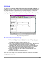
3.3 Rulers & Guides
Rulers and Guides are on-screen designing aids that allow you to quickly position and measure
objects on the plate.
Rulers
Rulers allow real-world visual positioning and alignment of objects in the Draw Area. The rulers
appear along the top and left sides of the Draw Area and show Inches or Millimeters whichever is configured in the Plate Setup. As the zoom factor is changed, the rulers are changed
by the appropriate scale factor.
Fig. 3-6 Rulers & Guides
To display the rulers, select the Show Rulers command in the View Menu. A checkmark will
appear next to the command, indicating that it is a toggle, and that it is currently active. To
dismiss the rulers, simply select the Show Rulers command again.
Guides
Guidelines, or "guides", are extension lines for the rulers. Guides appear as dotted lines that
extend across the Draw Area from the top or left ruler. Each guide corresponds with an
appropriate tick mark on the associated ruler to more easily see the positioning of certain objects.
61
To create a guide, position the cursor over a ruler and drag it into the draw area. Dragging from
the top creates a horizontal guide, and dragging from the left creates a vertical guide. There are a
maximum of eight vertical and eight horizontal guidelines.
Positioning the cursor over it and dragging it to a new position may move a guide.
Guides can be removed via the Remove Guidelines command in the View Menu. This command
erases and destroys all guides currently defined in the Draw Area.
62
3.4 Maximizing the Available Draw Area
Status Line Toggle
The status line may be disabled to provide more space for the Draw Area. This is achieved via
the Show Status Line command in the Options Menu. This command acts as a toggle. Selecting
the Show Status Line command alternately enables and disables the status line.
Tool Bar Toggle
The tool bar may be disabled to provide more space for the Draw Area. This is achieved via the
Show Tool Bar command in the Options Menu. This command also acts as a toggle. Selecting
the Show Tool Bar command alternately enables and disables the tool bar.
63
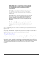
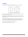
3.5 Preview
A JLS work file can be visually verified via the Preview option. Preview shows a
representation of the complete plate on-screen, without the bounding rectangles, using highresolution fonts. Preview also provides access to the printer configuration and print commands.
The display is generated in color, with specific colors corresponding to specific cutter
specifications.
Fig. 3-7 Preview
The Preview main window, or Preview Area, is similar to the main JLS Draw Area and displays
the same components, though functionality is more restricted in the preview mode.
To preview the plate, select the Preview command from the Execute Menu in JLS. Press
the Esc key to end the preview.
The Preview Area
The Preview Area displays the JLS Plate. The actual content of the display is affected by a
number of configurable parameters, including:
•
•
•
The color of the cutter path (defined as part of the tool configuration section)
The type of path displayed (cutter path and/or the actual programmed path may be
displayed)
Scoring (if defined)
The zoom commands and scroll bars can be used to display a small section of the plate/symbol in
more detail.
64
The Tool Bar
The tool bar provides the same quick and easy function selection available in the main JLS
window. The tool bar may be switched off (and on) in the Options menu.
Not all JLS pushbutton icons are available from Preview; however, each icon operates in exactly
the same manner as in the main JLS window.
Zooms
The standard zoom buttons, including zoom plate, magnify, zoom selected, zoom previous, and
redraw are available. Each zoom button operates in exactly the same manner as the zooms in the
main JLS window. (These functions are also available from the View Menu.)
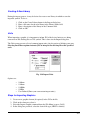
Setting the Batch Number
The Set Batch button is used to select the index of the desired batch to be viewed. This batch
number is used to establish the correct serializing and variable text on the plate. (This function is
also available from the Preview Menu.)
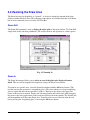
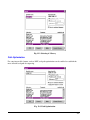
Printing
The Print button on the tool bar provides local printer access. To print the plate image to the
(default) printer, select the Print command from the Preview Menu. The current screen contents
will be transmitted to the printer.
After selecting the Print command, a dialog box will appear to establish how the image will
appear on the printed page:
Fig. 3-8 Printing Options
Select the Current View option and click OK to print the current contents of the Preview Area, at
the current zoom factor. When this option is selected, the Preview Area is scaled such that it will
fit entirely on the printed page. A border is added, including the work file name and the date of
the printing.
65
Select the Actual Size option and click OK to print the work file at its actual size. When this
option is selected, a 2" x 4" plate will appear on the page at precisely 2" x 4", and without a
border.
After selecting the desired print option, a status message will briefly flash on the screen to show
that a printing operation is about to take place.
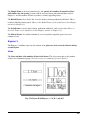
Print Setup
The Print Setup button is used to configure the local printer. Configurable parameters include:
•
•
•
Paper size and orientation (portrait or landscape)
Configuration of printer connections (LPT1, COM1, etc)
Miscellaneous printer parameters (print quality, density, etc.)
Refer to the Windows™ User Guide for a full description of how Windows™ handles printing
using the Control Panel and Print Manager.
Fig. 3-9 Example Printer Setup
Help By Pointing
The Help-By-Pointing button starts the help system on the object or item pointed to by the
cursor. To get help, press the Help-By-Pointing button (the cursor changes to an arrow with a
question mark), move the cursor so that the arrow points to the desired topic, and click the
mouse. This button works in Preview the same as it works in the main JLS window.
66
Tool Box
The Tool Box is available from the Preview Menu and is used to configure the tools that will
be used to produce/display the plate. The toolbox provides configuration/setup facilities for the
length, diameter, and spindle for each defined tool, as well as complete control over each cutting
specification.
The Tool Box is especially important in Preview, since it is in the Tool Box that one configures
the colors for each cutting spec.
(See Chapter 8 for more on the Tool Box.)
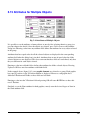
Fig. 3-10 Tool Box with Drawing Color
Preview Display Options
Displaying Profiles
The Show Profile command in the View Menu sets the Preview Area to display the plate,
showing the characters and elements with a thin line. The color of this line corresponds to the
Drawing Color set in the Toolbox for the particular cut spec assigned to the character/element.
Displaying the Tool Path
The Show Tool Path command in the View Menu sets the Preview Area to display the plate
using a dashed line to trace the tool path. The tool path is the trajectory of the center of the
67
tool, which may correspond with the profile, or may be offset, depending on the Path Type
configured in the Toolbox for the particular cut spec.
Displaying Outlines
The Show Outline command in the View Menu sets the Preview Area to display the plate using
an appropriate line thickness to simulate the tool diameter. This option shows the width of
the cut along the tool path.
Displaying Job Matrices
The Show Matrixed Jobs command in the View Menu toggles the display to show the entire
matrix (if any) with any variable text and serialization, or is used to suppress it and show only
the first job in the matrix.
Displaying Long Plate/Tall Plate Partitions
The Show Partitions command in the View Menu toggles the display to show the entire Long
Plate or Tall Plate with all text, or to show only the first partition in the sequence.
Rulers and Guides
It is possible to display the rulers and guides in the Preview Area using the appropriate
commands in the View Menu.
Note: See the discussion of Rulers & Guides at the beginning of this chapter for more details.
68
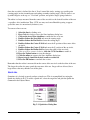
3.6 Unit Preferences
The Unit Preferences command in the Options Menu allows you to configure the way JLS
displays numbers.
Fig. 3-11 Unit Preferences
Setting the options in the Unit Preferences dialog box sets the type of units used to display
numbers system-wide.
Linear units may be displayed in inches, millimeters, centimeters, or meters.
Angular units may be displayed in degrees, degrees-minutes-seconds, radians, or revolutions.
Linear Velocity may be displayed in inches per second, millimeters per second, centimeters per
second, meters per second, inches per minute, millimeters per minute, centimeters per minute, or
meters per minute.
Angular Velocity may be displayed in degrees per second, radians per second, degrees per
minute, radians per minute, or revolutions per minute.
Time may be displayed in seconds, milliseconds, minutes, or hours-minutes-seconds.
69
Chapter IV - JLS Objects
A JLS work file consists of various different items, such as lines and graphics. These items are
referred to as objects. A plate can contain many different types of objects or many of the same
types of objects. The content is completely determined by the user at the time of creation.
4.1 Plates
The Plate is a single piece of engraving material. There is only one plate for every JLS session.
(The New command from the File Menu abandons the current plate and creates a new one.)
To create a Plate, select the New command from the File Menu. This generates the Plate Setup
dialog box and allows you to set up the general plate specs as well as select the desired job
creation method.
Note: Consult Chapter 2 for more details on creating a Plate.
Fig. 4-1 Plate Setup Dialog Box
70
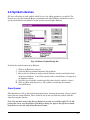
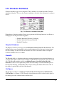
4.2 Jobs
The Job is the object that represents work for one particular purpose or customer, say for
one sign or one plaque. A job is positioned according to its lower-left corner.
Fig. 4-2 Creating a New Job
To Create (add) A Job Interactively:
1. Click the Add Mode button on the JLS tool bar to enter Add Mode.
A small cross is displayed next to the cursor.
2. Click the Job Level button on the tool bar to select Job Level. This
focuses our attention on Jobs and causes all creation and selection
operations to be constrained to Jobs.
3. Move the cursor to the position on the plate that corresponds to the
upper-left corner of the Job. Press and hold the left mouse button.
4. Drag the mouse to the lower right so that the rectangle defines the
desired boundaries of the Job.
5. Release the mouse button to complete the process.
A new Job is created within the area just defined, which has the specifications, or "attributes", of
the previously created Job.
71
Fig. 4-3 Job Attributes
To Create (add) a Job Manually:
1. Click the Add Mode button on the JLS tool bar to enter Add Mode.
2. Click the Job Level button on the tool bar to select Job Level. This focuses our
attention on Jobs and causes all creation and selection operations to be
constrained to Jobs.
3. Select the Create Job command from the Objects Menu (or simply press the '+'
key on the numeric keypad). A new Job is created and its specification is
displayed in a dialog box for you to edit/verify. The specifications, or "attributes",
are defined by the default job attributes stored in the EPS.INI file.
4. Set up the Job's parameters as desired (height, width, position, etc.) and click on
OK.
Jobs can only be created if a plate is defined in the current workspace.
72
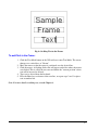
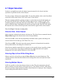
4.3 Frames
A Frame is an object that represents a number of similar lines of text. A Frame contains lines
that have similar height, spacing, and/or margins. A Frame may contain a single line or multiple
lines of text. All lines in the frame originate with the same left and right margins and have the
same interline spacing. (The text lines in a frame may be manipulated independently after the
frame has been created.) A Frame is positioned according to its lower - left corner.
Fig. 4-4 Creating A New Frame
To Create (add) A Frame Interactively:
1. Click the Add Mode button on the JLS tool bar to enter Add Mode (this step is
not necessary if JLS is already in Add Mode). A small cross will be displayed
next to the cursor when it is moved into the Draw Area.
2. Click the Frame Level button on the tool bar to select Frame Level. This focuses
our attention on Frames and causes all creation and selection operations to be
constrained to Frames (this step is not necessary if JLS is already at Frame Level).
3. Move the cursor to the position on the plate that corresponds to the upper-left
corner of the Frame and press the left mouse button (holding it down).
4. Drag the mouse to the lower right so that the rectangle defines the desired
boundaries of the Frame.
5. Release the mouse button to complete the process.
A new Frame is created within the area just defined, which has the specifications, or "attributes"
of the previously created Frame.
73
The Frame is created with the default number of lines (commonly 3). Selecting the Edit
Attributes command from the Edit Menu and setting the number of lines to the desired number
can change this.
Fig. 4-5 Frame Attributes
To Create (add) a Frame Manually:
1. Click the Add Mode button on the JLS tool bar to enter Add Mode (this step is
not necessary if JLS is already in Add Mode).
2. Click the Frame Level button on the tool bar to select Frame Level. This focuses
our attention on Frames and causes all creation and selection operations to be
constrained to Frames (this step is not necessary if JLS is already at Frame Level).
3. Select the Create Frame command from the Objects Menu (or simply press the '+'
key on the numeric keypad). A new Frame is created, and its specification is
displayed in a dialog box for you to edit/verify. The specifications, or "attributes",
are defined by the default frame attributes stored in the EPS. INI file.
4. Set up the Frame's parameters as desired (height, width, position, etc.) and click
on OK. Pay special attention to the Lines field as this establishes the number of
lines in the Frame. (The Frame's parameters, or "attributes", are discussed in
detail in the next chapter.)
Newly created Frames are attached to the currently selected job. Frames can only be created if a
job is defined in the current workspace.
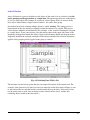
74
Fig. 4-6 Adding Text to the Frame
To add Text to the Frame:
1. Click the Text Mode button on the JLS tool bar to enter Text Mode. The cursor
changes to a vertical bar, or "I-beam".
2. Move the mouse so that the cursor is positioned over the desired line.
3. Click the mouse. A flashing divider bar will appear on the line where the mouse
was clicked. This is called the text caret and marks the "current position" where
text will be inserted or deleted.
4. Type text as desired from the keyboard.
5. Press the Enter key to advance to the next line, or repeat steps 2 and 3 to place
text on another line.
Note: For more details on editing text, consult Chapter 6.
75
4.4 Lines
This object represents text, or a number of characters with the same height and baseline, and
is analogous to the 'line' in the EC software. Lines are positioned according to their Justification.
For example, in the X-axis, a center-justified line is positioned according to its center, a leftjustified line is positioned according to its left side, and a right-justified line is positioned
according to its right side. This same concept holds true for top-, middle-, and bottom- (baseline)
justification in the Y-axis.
Fig. 4-7 Creating a New Line
To Create (add) A Line Interactively:
1. Click the Add Mode button on the JLS tool bar to enter Add Mode (this step is
not necessary if JLS is already in Add Mode). A small cross will be displayed
next to the cursor when it is moved into the Draw Area.
2. Click the Line Level button on the tool bar to select Line Level. This focuses our
attention on Lines and causes all creation and selection operations to be
constrained to Jobs (this step is not necessary if JLS is already at Frame Level).
3. Move the cursor to the position on the plate that corresponds to the upper-left
corner of the Line and press the left mouse button (holding it down).
4. Drag the mouse to the lower right so that the rectangle defines the desired
boundaries of the Line.
5. Release the mouse button to complete the process.
A new Line is created within the area just defined, which has the specifications, or "attributes",
of the previously created Line.
76
Fig. 4-8 Line Attributes
To Create (add) a Line Manually:
1. Click the Add Mode button on the JLS tool bar to enter Add Mode (this step is
not necessary if JLS is already in Add Mode).
2. Click the Line Level button on the tool bar to select Line Level. This focuses our
attention on Lines and causes all creation and selection operations to be
constrained to Lines (this step is not necessary if JLS is already at Line Level).
3. Select the Create Line command from the Objects Menu (or simply press the '+'
key on the numeric keypad). A new Line is created, and its specification is
displayed in a dialog box for you to edit/verify. The specifications, or "attributes",
are defined by the default line attributes stored in the EPS.INI file.
4. Set up the Line's parameters as desired (height, width, position, etc.) and click on
OK.
Newly created Lines are attached to the currently selected job. Lines can only be created if a job
is defined in the current workspace.
Fig. 4-9 Adding Text to the Line
77
To add Text to the Line:
1. Click the Text Mode button on the JLS tool bar to enter Text Mode. The cursor
changes to a vertical bar, or "I-beam".
2. Move the mouse so that the cursor is positioned over the line.
3. Click the mouse. A flashing divider bar will appear on the line where the mouse
was clicked. This is called the text caret, and marks the "current position" where
text will be inserted or deleted.
4. Type text as desired from the keyboard.
Note: For more details on editing text, consult Chapter 6.
78
4.5 Elements
An element is an object that represents a single, engrave-able item, such as a Graphic or
Profile. Font characters are also treated as Elements for purposes of moving, rotating, slanting,
etc. Elements are positioned according to their lower-left corner.
Fig. 4-10 Creating a New Element
To Create (add) An Element Interactively:
1. Click the Add Mode button on the JLS tool bar to enter Add Mode (this step is
not necessary if JLS is already in Add Mode). A small cross will be displayed
next to the cursor when it is moved into the Draw Area.
2. Click the Element Level button on the tool bar to select Element Level. This
focuses our attention on Elements and causes all creation and selection operations
to be constrained to Elements (this step is not necessary if JLS is already at
Element Level).
3. Move the cursor to the position on the plate that corresponds to the upper-left
corner of the Element and press the left mouse button (holding it down).
4. Drag the mouse to the lower right so that the rectangle defines the desired
boundaries of the Element.
5. Release the mouse button to complete the process.
A new Element is created within the area just defined, which has the specifications, or
"attributes", of the previously created Element.
79
Fig. 4-11 Element Attributes
To Create (add) an Element Manually:
1. Click the Add Mode button on the JLS tool bar to enter Add Mode (this step is
not necessary if JLS is already in Add Mode).
2. Click the Element Level button on the tool bar to select Element Level. This
focuses our attention on Elements, and causes all creation and selection operations
to be constrained to Elements (this step is not necessary if JLS is already at
Element Level).
3. Select the Create Graphic command from the Objects Menu (or simply press the
'+' key on the numeric keypad). A new Graphic Element is created, and its
specification is displayed in a dialog box for you to edit/verify. The specifications,
or "attributes", are defined by the default element attributes stored in the
EPS.INI file.
4. Set up the Element's parameters as desired (height, width, position, etc.) and click
on OK.
Newly created Elements are attached to the currently selected job. Elements can only be created
if a job is defined in the current workspace.
To assign ("browse") a graphic symbol to the new Element, see the next section - Symbol
Libraries.
80
4.6 Symbol Libraries
JLS uses collections of stock symbols called libraries for adding graphics to a work file. The
libraries are accessible using the Browse command in the Objects Menu, which allows you to
specify which library and symbol is loaded into the current Graphic Element.
Fig. 4-12 Browse Symbol Dialog Box
To define the symbol content of an Element:
1. Click on an Element to select it.
2. Select the Browse command from the Objects Menu.
3. Review the list of libraries displayed in the Libraries window and double-clicks
on the desired Library. A list of the symbols in the selected library is displayed in
the Symbols window.
4. Scroll the list of available symbols and click on the desired symbol to select it.
5. Click on OK to finish the process. The symbol is loaded into the currently
selected Element.
Draw Symbol
This button directs JLS to update the background display, showing the currently selected symbol
loaded into the current Element. This is useful if you are not sure what the symbols look like
when browsing the libraries.
Note: You may have to move the Browse dialog box in order to reveal the symbol. To do this,
position the cursor over the title bar of the Browse dialog box, depress the left mouse button,
drag the box to one side, and release the mouse button.
81
4.7 Object Selection
In order to accomplish most tasks, the objects in question must first be selected, and then
operations are performed on the selected objects.
To select an object, JLS must be in Select Mode. To enter Select Mode, click on the Select Mode
icon on the tool bar (white arrow). JLS is now ready to select objects.
The most common method for selecting an object is to place the cursor inside the boundary of
the object and click the mouse. The object will then appear to have a number of small "dots"
around its perimeter to show that it has been selected. These "dots" are called nodes and may
appear as different shapes depending on the current state of the tool bar. Once the nodes appear,
the object has been selected, and all operations enacted will be applied to this selected object.
Note: See Chapter 7 for more on using nodes.
Selection State - Select Nearest
Object selection is affected by the current selection state. The Select Nearest command from the
Objects Menu toggles the selection state to one of two possibilities:
Select Nearest ON - Selects the item immediately beneath the mouse pointer and changes the
current selection level to that type (Job, Frame, Line, etc.).
Select Nearest OFF - Selects the item at the current selection level immediately beneath the
mouse pointer and does not change the selection level.
Select Nearest should be turned ON if it is desired to select specific objects (regardless of their
level), or to successively select objects at different levels, where this mode saves explicit
changing of levels on the toolbar. Otherwise it is best left OFF.
Selecting Objects From Within Dialog Boxes
Objects can also be selected by pressing the Next or Prev keys in certain dialog boxes. The
selection will move from the current object in the existing order to the next or previous object
respectively.
Selecting Multiple Objects
In JLS it is possible to select more than one object at a time. The only requirement is that all
objects selected at one time must be of the same level (i.e. Jobs, Frames, or Lines). This allows
the user to perform a single operation on all the selected objects in a single pass, thus saving time
and preventing inadvertent omission of objects.
82
Active Selection
Active Selection is a process in which several objects of the same level are selected so that the
entire grouping can be operated on as a single unit. Subsequent operations act on the objects
as if it is a single object. For example, if an actively selected group of lines is rotated, all the
lines will be rotated about a single center of rotation - the center of the group.
One method of actively selecting multiple objects is called "netting". The netting process is
characterized by the user drawing a rectangle around the objects to be selected. This process
selects objects within the area bounded by the rectangle, or net, instead of limiting the selection
to a single object. To net some objects, place the mouse pointer in the upper-left corner of the
imaginary rectangle that bounds the objects. Depress the left mouse button and drag the mouse
diagonally such that the rectangle surrounds all the objects scheduled for selection. Operations
applied to this grouping will be applied to the group as a whole.
Fig. 4-13 Selecting Lines With A Net
The net must start and end on points that are not occupied by objects of the current level. For
example, if the current level is Line Level and you intend to net the lines inside a Frame, be sure
to start and end the net such that no lines extend outside the area of effect. (You could, in fact,
net the entire frame as well, since no frames can be selected in Line Level, and the only
remaining objects would be the lines inside.)
83
Fig. 4-14 Active Selection of Lines
Another method of active selection is accomplished by using a "shift-click" key combination. In
this process, one of the objects in the grouping is selected first by clicking on it. Then the user
holds the Shift key down and successively clicks on each individual object remaining in the
grouping. Finally, the Shift key is released. This process allows multiple objects of the same
level to be selected, even if they are positioned randomly around the plate and are not positioned
optimally enough for netting.
Passive Selection
Passive Selection, unlike active selection, is a process in which several objects of the same level
are selected so that all objects in the grouping are manipulated individually, in the same
manner as the initial object selected in the group. For example, if a passively selected group of
lines is rotated, each line will be rotated about its own individual center of rotation - not the
center of the group.
The passive selection method is involves use of a "control-shift-click" key combination to make
the selection. In this process, one of the objects in the grouping is selected first by clicking on it.
The usual selection nodes appear around it. Then the user holds both the Ctrl and Shift keys
down and successively clicks on each individual object remaining to be selected in the grouping.
Smaller, black nodes appear around the entire grouping. Finally, the Ctrl and Shift keys are
released.
Fig. 4-15 Passive Selection Of Characters
84
Select Nearest Revisited
The Select Nearest command toggles the selection state of JLS. If Select Nearest is turned ON,
the above selection processes are difficult, if not impossible. This is because when Select Nearest
is ON, there is no default level and the software may not be able to deduce which objects of
which level should be included in the grouping. Remember to turn Select Nearest OFF for
multiple-object selections.
Selecting Text in Text Mode (Shift-Drag)
To select text in Text Mode, place the text caret (I-beam) immediately before the first character
that is to be selected. Press the left mouse button and drag the text to the left (and down if
required) until it is positioned immediately after the last character to be selected. Release the
mouse button. Each character between the first character and the last character has been selected,
and is highlighted to reflect its selected status. All subsequent operations (i.e. Cut/Paste) will be
applied to the selected text. This method of selecting text is valid for WYSIWYG text editing
and for editing in the simple text editor.
Fig. 4-16 Selecting Text In Text Mode
To select ALL the text in the current frame, simply click on a line in the desired frame, and then
click on the Select All command in the Edit Menu.
85
4.8 Aligning Objects
The Align function positions an object so that its center is aligned with the center of another
object.
Fig. 4-17 Aligning a Line with a Graphic
To align an object:
1.
2.
3.
4.
5.
6.
7.
Select the "reference" object (in Select Mode).
Open the Objects Menu.
Select the Set Alignment Point command.
Select the "target" object (in Select Mode).
Open the Objects Menu.
Select the Align command.
Choose Vertical, Horizontal, or Central alignment.
86
Fig. 4-18 (Vertical) Aligned Line and Graphic
The center of the desired object, or "target", is automatically aligned with the center of the
"reference" object. The Align function automatically repositions the target object based on the
type of alignment desired:
•
•
•
Vertical - vertical centerline is the same as the reference object.
Horizontal - horizontal centerline is the same as the reference object.
Center - center is exactly the same as the reference object.
87
Chapter V - Object Attributes
Every object has descriptive characteristics called attributes. These characteristics, such as
Height, Width, X&Y Position, etc., combine to form a complete description of the object and
can be changed by the user to suit his needs.
5.1 Setting an Object's Attributes
To set an object's attributes, click on the object to select it, and then select the Edit Attributes
command from the Edit Menu. (Or, select the object and press Ctrl-A.) The attribute dialog
box for the currently selected object is displayed, along with all appropriate attributes for
examination and editing.
Fig. 5-1 Object (Line) Attribute Dialog Box
To edit a particular attribute, click on the desired attribute field with the mouse, or press the tab
key until the desired attribute field is highlighted. Delete the existing attribute value and enter a
new value.
Double-clicking the field not only selects the desired attribute field, but also highlights the
attribute value so that a new one can be entered directly from the keyboard, without having to
delete the old value first.
88
5.2 Attribute Dialog Box Controls
This section explains the controls found in the attribute dialog boxes.
OK
The OK button is the standard method of exiting an attribute dialog box and saving the changes.
When OK is pressed, all the changes to the attribute settings are applied to the currently selected
object(s). The attribute editing session is terminated, and the attribute dialog box is closed.
Control returns to the main JLS window.
Cancel
The Cancel button is the standard method of exiting an attribute dialog box and abandoning the
changes. When Cancel is pressed, all un-saved changes to the attribute settings are ignored,
the attribute editing session is terminated, and the attribute dialog box is closed. Control returns
to the main JLS window. Permanent changes applied via the Update or Layout buttons (see
below) are established before canceling, and cannot be undone using the Cancel button.
Help
The Help button is the standard method of getting help on the current dialog box operations.
When Help is pressed, the JLS help system is invoked and help is displayed about the current
operation.
Update
The Update button allows ongoing examination of changes to the selected object as a result of
changing attribute values. Pressing Update is the same as pressing OK, except that the
attribute editing session is not closed. After pressing Update, the attribute dialog box
disappears, allowing you to examine the changes. The cursor is changed to a small black box
in order to remind you that operations in the Draw Area are temporarily suspended. Click
the mouse or press any key to return the dialog box to the screen and continue.
Prev & Next
The Prev & Next buttons accept any changes to the currently selected object and then cause the
previous or next object (at the same Level) to be selected for editing.
For example, consider a JLS plate with three lines. By selecting the middle line and pressing
Ctrl-A, the Line Attributes dialog is invoked on the middle line. Pressing the Prev button accepts
any changes to the middle line, and then selects the first line for editing. Likewise, pressing the
Next button accepts any changes to the middle line, and then selects the last line for editing.
89
Set As Default
The purpose of this function is to save the current attributes as default values. When the Set As
Default button is depressed, the current attribute settings for the dialog box are saved to disk.
(Default values are saved in EPS.INI in the c:\windows directory.) All displayed attribute values
are updated. In the case of objects with variable types (i.e. "straight" lines vs. "arc"), only the
displayed attributes are updated.
After default values have been set, they are used thereafter, each time a new object (of the same
type) is created, via the Create command in the Objects Menu, or the (+) shortcut key.
The default attribute values are stored in the EPS.INI file located in the WINDOWS™ directory.
To restore the default values for ALL object types, use the Load System Defaults command in
the Objects menu.
Note: When creating objects interactively (that is, using the mouse in Add Mode), the default
settings assigned to the new object are established by the most recently created object of that
type - NOT THE SYSTEM DEFAULTS.
Exiting the Attribute Dialog Box
When the attributes are correctly set, press OK.
90
5.3 Standard Attributes
Standard attributes are parameters that are applicable for all JLS objects. For example, every
job, frame, line, etc. has a height and a width. Therefore, height and width are said to be standard
attributes. A Height field and a Width field are found in every attribute dialog box.
X Position
The X Position attribute is the distance from the position reference point (usually the lower left
corner) of the object to the origin, in the x-axis.
Y Position
The Y Position attribute is the distance from the position reference point (usually the lower left
corner) of the object to the origin, in the y-axis.
Horizontal (x) Position Reference
The Horizontal Position Reference is used to locate the object on the plate, in the x-axis. This is
usually Left (for the lower-left corner of the object), but it can be Left, Center, or Right, as
desired.
Vertical (y) Position Reference
The Vertical Position Reference is used to locate the object on the plate, in the y-axis. This is
usually Bottom (for the lower-left corner of the object), but it can be Bottom, Middle, or Top, as
desired.
Height
The Height attribute is the vertical height of the object.
Width
The Width attribute is the horizontal width of the object.
Rotate
The Rotate attribute is the degree of rotation of the object. Zero degrees is the default angle of
rotation, and represents the "normal" object orientation. Positive slant angles represent counterclockwise rotations. Negative slant angles represent clockwise rotations.
91
Slant
The Slant attribute is the degree of slant of the object. Zero degrees is the default angle of slant,
and represents the "normal", or un-slanted, object. Positive slant angles represent a rightward
shift of the upper portion and a corresponding leftward shift of the lower portion, as in italic
type. Negative slant angles slant in the opposite way.
Reflect
The Reflect attribute is the object's reflection along X-, Y-, or X- and Y-axes (or not at all, which
is the default).
92
5.4 Using Standard Attributes
Setting the Height of an Object
Entering a new value into the Height attribute field can change the height of any object.
To set the height of a job, frame, line, or element:
1.
2.
3.
4.
5.
6.
7.
8.
Select the object by clicking on it.
Press Ctrl-A in order to access the object's attribute dialog box.
Double-click on the Height attribute field to select it.
Enter the new height value, in inches or millimeters.
Press the Update button to view the changes.
Click the mouse to return to the attribute dialog box.
Repeat steps 3-6 until the desired results are achieved.
Press the OK button to conclude the session.
Note: Changing the height of frames or lines causes the associated text to be updated
automatically in conjunction with the Layout attributes (frames) and Layout Defaults
attributes (frames & lines). This is to reset the character heights, line spacing, margins,
condensing, etc. based on the new height. Any special changes to individual characters will be
abandoned.
Setting the Width of an Object
Entering a new value into the Width attribute field can change the width of any object.
To set the width of a job, frame, line, or element:
1.
2.
3.
4.
5.
6.
7.
8.
Select the object by clicking on it.
Press Ctrl-A in order to access the object's attribute dialog box.
Double-click on the Width attribute field to select it.
Enter the new width value, in inches or millimeters.
Press the Update button to view the changes.
Click the mouse to return to the attribute dialog box.
Repeat steps 3-6 until the desired results are achieved.
Press the OK button to conclude the session.
Note: Changing the width of frames or lines via their attribute values causes the associated
text to be updated automatically in conjunction with the Layout attributes (frames) and Layout
Defaults attributes (frames & lines). This is to reset the text based on the new width. Any
special changes to individual characters will be abandoned.
93
Positioning JLS Objects
The position of an object depends on two aspects of the engraving setup: the plate Origin, and
the object's Position Reference.
Fig. 5-2 Object Positioning
The Origin is the established (0,0) position on the Plate. All measurements in JLS are made
from this position.
The Position Reference is a point on a JLS object that establishes its position. The reference
point for most JLS objects is fixed in the lower left corner of the object.
Based on these two concepts, an object's position is described by the X Position and Y
Position attributes. X Position is defined as the distance in the x-axis from the Origin to the
object's Reference Point. Similarly, the Y Position is defined as the distance in the y-axis from
the Origin to the object's Reference Point.
In figure 5-2, above, the selected element is defined at X Position 2.5, and Y Position 8.0. This
means that the distance from the origin to the lower left corner of the graphic is 2.5 in the x-axis
and 8.0 in the y-axis.
The Position Reference indicates how the object will be positioned on the plate. The most
conventional setting is the" lower-left corner", or Left/Bottom.
94
Fig. 5-3 Conventional Position Reference
In figure 5-3 above, the "arrow" element is at position: (x=2.5", y=8.0")
This distance represents the distance from the "lower-left corner" of the object to the plate
origin.
Many other options are available for setting the position reference. Another popular option is
"central", or Center/Middle.
Fig. 5-4 "Central" Position Reference
In Figure 5-4 above, the "arrow" element is at position: (x=5.0", y=5.75").
This distance represents the distance from the "center" of the object to the plate origin.
95
To set the position of an object:
1. Select the object by clicking on it.
2. Press Ctrl-A to access the object’s attribute dialog box.
3. Check/set the Horizontal and Vertical Position Reference.
4. Double-click on the X-Position attribute field to select it.
5. Enter the new x-axis position value, in inches or millimeters.
6. Repeat steps 4-5 for the Y-Position attribute.
7. Press the Update button to view the changes.
8. Click the mouse to return to the attribute dialog box.
9. Repeat steps 4-8 until the desired results are achieved.
10. Press the OK button to conclude the session.
Fig. 5-5 Horizontal Positioning Of Lines (X Pos=5.0)
The Position Reference for a text Line is a special case, and is established according to the
Justification attributes defined in the Line Attributes dialog box (described later in this chapter).
In the Horizontal, Left-justified text lines are positioned according to the left side of the line.
Right-justified text lines are positioned according to the right side of the line, and center-justified
text lines are positioned according to their center.
In the Vertical, Top-justified text lines are positioned according to the top of the line. Bottomjustified text lines are positioned according to the bottom, or baseline of the line (default), and
middle-justified text lines are positioned according to their midline.
Rotating an Object
Any object can be rotated about its reference point by changing the rotate attribute.
96
Fig. 5-6 Rotating A Graphic
To rotate an object:
1.
2.
3.
4.
5.
6.
7.
Select the object by clicking on it; then press Ctrl-A.
Double-click on the rotate attribute field to select it.
Enter the new rotation value, in degrees (positive angles are CCW).
Press the Update button to view the changes.
Click the mouse to return to the attribute dialog box.
Repeat steps 2-5 until the desired results are achieved.
Press the OK button to conclude the session.
Note: Changing the Rotate attribute causes the object to be rotated about its reference point.
This is different than the Rotate Transform, which uses the center of the object as its rotation
point (see Chapter 7).
97
Slanting an Object
Changing the Slant attribute can slant any object.
Fig. 5-7 Slanting A Line
To slant an object:
1.
2.
3.
4.
5.
6.
7.
8.
Select the object by clicking on it.
Press Ctrl-A in order to access the object's attribute dialog box.
Double-click on the Slant attribute field to select it.
Enter the new slant value, in degrees (positive angles for italics).
Press the Update button to view the changes.
Click the mouse to return to the attribute dialog box.
Repeat steps 3-6 until the desired results are achieved.
Press the OK button to conclude the session.
98
Reflecting an Object
Changing the Reflect attribute can reflect any object.
Fig. 5-8 Reflecting A Graphic Element
To reflect (mirror) an object:
1.
2.
3.
4.
Select the object by clicking on it.
Press Ctrl-A in order to access the object's attribute dialog box.
Double-click on the Reflect attribute field to select it.
Select the new reflection:
•
•
•
•
5.
6.
7.
8.
None (default)
X
Y
X and Y
Press the Update button to view the changes.
Click the mouse to return to the attribute dialog box.
Repeat steps 3-6 until the desired results are achieved.
Press the OK button to conclude the session.
99
5.5 Job Attributes
Job Attributes are available from the Job Attributes dialog box, which is displayed by selecting
the desired job(s) and pressing Ctrl-A.
Fig 5-9 Job Attributes Dialog Box
Manipulation of job attributes allow you to perform the following functions, in addition to
changing the size and position of the job:
o
o
Scoring
Matrix
Scoring
The Score attribute refers to the use of boundary lines around the job and associated
matrix items. Options are:
o
o
o
o
Complete- Solid lines around and between matrix items.
Perimeter- Solid lines around entire matrix.
Partial Scoring- Dotted lines around and between matrix items.
None- No boundary lines.
Comment
The Comment attribute is a three-line text message that serves as a note about the selected job.
Enter any text you wish, including creation date, job type, purpose, etc. This message can be
displayed on the AMC controller’s front-panel display.
100
Repeats
The Repeats section in the Job Attributes dialog box allows you to specify an automatic job
matrix. This is useful when producing many jobs of the same specification - with different text.
Job matrixing supports Serialization and Variable Text to allow automatic updates of text on
consecutive matrix items. The procedure for defining repeats in a matrix is discussed later in this
chapter.
Repeat Across
The Repeat Across attribute is the number of times the job repeats across the plate, from HOME.
(Note: The plate should be of sufficient size to accept all matrix items.)
Repeat Down
The Repeat Down attribute is the number of times the job repeats down the plate, from HOME.
(Note: The plate should be of sufficient size to accept all matrix items.)
Spacing Across
This attribute is the distance between the left side of a matrix item and the left side of an adjacent
matrix item. That is, the relative horizontal position of the next item in the matrix. The default is
equal to the job width, which positions consecutive matrix items so that they just touch.
Spacing Down
This attribute is the distance between the base of a matrix item and the base of an adjacent matrix
item. That is, the relative vertical position of the next item in the matrix. The default is equal to
the job height, which positions consecutive matrix items so that they just touch.
Auto Spacing
The Auto Spacing checkbox controls how spacing for matrix items is determined. Checking the
Auto Spacing checkbox instructs JLS to insert the job width and height for Spacing Across and
Down. Leaving the Auto Spacing checkbox unchecked enables you to enter custom offsets.
Keep Size as Plate
This checkbox enables automatic re-sizing of a Simple Job whenever the plate size is altered. If
the Keep Size As Plate checkbox is checked, changing the plate size automatically:
o
o
o
Updates the Job size
Updates the size of the Single Frame
Performs a Layout on the text in the Single Frame
101
This is useful if you need to quickly re-adjust the overall size of your work.
Enabling this feature disables manual setting of the following attributes:
o
o
o
o
o
o
o
Position
Position Reference
Height
Width
Rotate
Slant
Reflect
102
5.6 Using Job Attributes
Setting up a Matrix
As stated earlier, the Repeats section in the Job Attributes dialog box allows you to specify an
automatic job matrix. Job matrixing utilizes Serialization (Chapter 12) and Variable Text
(Chapter 11) to allow automatic updates of text on consecutive matrix items.
Fig. 5-10 Matrix Of Jobs (With Complete Scoring)
To set up a matrix:
1.
2.
3.
4.
5.
6.
Select the desired job by clicking on it.
Enter the desired number of items across in the Across field.
Enter the desired number of items down in the Down field.
If Auto Spacing is desired, proceed to step 8.
Click on the Auto Spacing checkbox to disable automatic spacing.
Enter the desired spacing across in the Spacing Across field. Be sure to
consider any extra room needed for the tool diameter, shear, etc.
Note that enabling Auto Spacing for the frame causes JLS to automatically offset the
matrix columns for the tool diameter listed in the Tool Box.
•
Enter the desired spacing down in the Spacing Down field. Be sure to consider
any extra room needed for the tool diameter, shear, etc.
103
Note that enabling Auto Spacing for the frame causes JLS to automatically offset the
matrix rows for the tool diameter listed in the Tool Box.
•
Review your work and press the OK button when finished.
Defining Scoring
To establish bounding lines or tick marks around the job and associated matrix items, set the
appropriate option in the Job Attributes dialog box:
1. Click on the Score field.
2. Select the desired scoring option:
o
o
o
o
Complete- Solid lines around and between matrix items.
Perimeter- Solid lines around entire matrix.
Partial Scoring- Dotted lines around and between matrix items.
None- No boundary lines.
3. Review your work and press the OK button when finished.
Note: JLS currently scores the matrix, applying any appropriate matrix offsets (across and
down) as defined in the Job Attributes. JLS assumes that the individual matrix items are
ADJACENT. Thus, entering (manual) matrix offsets that are greater than the width of the
tool, shear, etc., used to separate the matrix items, will cause any excess space to be added to
the right and/or bottom of each matrix item.
104
5.7 Frame Attributes
Recall that a frame is a grouping of lines with similar height and spacing. Control of these
attributes allows you to produce uniform, visually appealing text, quickly and easily.
The frame attributes are available from the Frame Attributes dialog box. To access the Frame
Attributes dialog box, select the desired frame(s) and press Ctrl-A.
Fig. 5-11 Frame Attributes Dialog Box
Manipulation of frame attributes allow you to perform the following functions, in addition to
changing the size and position of the frame:
o
o
o
o
o
o
Auto/Manual Layout of Text
Control Frame Margins
Control Line Spacing & Height
Control Condense Mode
Establish Columnized Text
Create Dials
Frame Type
The Frame Type attribute allows you to define the type of frame you are editing, and therefore its
particular function and features.
105
The Simple Frame is the most common type, and consists of a number of normal text lines
with similar size and spacing. Layout controls work in concert with other attributes such as
Engrave % and the number of Lines to produce a visually appealing layout.
The Radial Frame, also called a dial, is used to mark a circular graduation with labels. This is
useful for labeling control panels. (More on the Radial Frame can be found later in this Chapter,
and also in Chapter 13.)
The Scale Frame is used to mark a linear graduation with labels, such as for a ruler. (More on
the Scale Frame can be found later in this Chapter, and also in Chapter 13.)
The Matrix Frame, also called columnized, is used to produce regularly spaced rows and
columns of text.
Engrave %
The Engrave % attribute represents the amount of the plate area to be covered with text during
an auto-layout.
Lines
The Lines attribute is the number of lines in the frame. This also corresponds to the number
of lines in a columnnized group. (See later section on columnizing for more details.)
Fig. 5-12 Frame With Engrave % At 20% and 80%
106
Layout
The controls in the Layout section define how JLS will re-position lines and text associated with
Simple and columnized Frames when the Layout button is pressed.
Auto Heights
If Auto Heights is activated (checked), JLS assumes control of the heights of the lines in the
frame according to the specified Engrave% frame attribute and the Line Height Proportions line
attribute for each line.
If Auto Heights is not activated, the line heights are not changed during a Layout, but the text is
re-initialized using the current line size and position. Any individual changes to the spacing or
heights of the characters are lost.
Auto Margins
If Auto Margins is activated (checked), JLS assumes control of the frame margins. These are
established as a portion of the available space after the Line Heights are established, and are
applied uniformly to all lines in the frame.
If Auto Margins is not activated, the frame margins are not affected by Layout.
Auto Spacing
If Auto Spacing is activated (checked), JLS assumes control of the interline spacing of the
lines in the frame. This is established according to the available spacing after the Line Heights
are established.
If Auto Spacing is not activated, the Layout procedure does not affect the spacing of the lines.
The baselines remain unchanged.
Keep Size as Job
This checkbox enables automatic re-sizing of a Frame whenever the job size is altered. If the
Keep Size As Job checkbox is activated (checked), changing the size of the job automatically:
o
o
Updates the Frame size
Performs a Layout of the text in the Frame
This is useful if you need to quickly re-adjust the overall size of your work.
Enabling this feature disables manual setting of the following attributes:
o
o
Position
Position Reference
107
o
o
o
o
o
Height
Width
Rotate
Slant
Reflect
Layout Defaults
The Layout Defaults represent initializing parameters. When Layout (Ctrl-L) is pressed, all the
lines in the selected frame are re-initialized using these default settings.
Req'd Condense
The Required Condense attribute is an overall condense value default setting for the lines in the
frame. After the type is set along the line, the entire text line is condensed to this default setting.
Note: If the text is still too large to fit within the line boundaries, it is condensed further, until
it fits.
A condense value of 100% means no condensing, and the type appears at its proper scale.
Emwidth
The Emwidth field is a default inter-character spacing adjustment for all lines in the frame, as a
percent of Em. (Em is defined as the width of a capital 'M' in the current font, and at its current
size.) For example, to insert additional space between all the characters, set Emwidth to 10% and
press the Layout button. This inserts 10% of the width of a capital 'M' between all characters.
Cutting Specs
The Cutting Specs attribute is a default cutting spec index, as defined in the JLS Tool Box (see
Chapter 8). Any lines added to the frame will have default cutting specs taken from this attribute.
Note: It is not currently possible to reset the cutting spec index for text by changing the Frame
Attribute default value. This is only applicable to new lines in the frame. To reset the cutting
spec index for any text, select the characters at Element Level and change the cutting specs in
the Character Attribute dialog box.
(Auto-) Condense Mode
Condense specifies how the lines in the frame are auto-condensed.
As needed causes all the lines in the frame to auto condense only if condensing is required to fit
text on a line.
108
The All Equal option causes JLS to auto-condense all the lines in the frame to the same value.
This is, of course, the lowest natural condense value of all the lines in the frame.
Equal Heights Equal causes all lines of equal height to auto-condense to the same value. This
works like the All Equal option, above, except that it is applied to certain groups of lines with
equal height instead of the entire frame.
Margins
Margins refer to the bordering white space of a frame. Manipulating the margins causes the text
to occupy more or less of the overall area:
Left
The Left Margin is the distance from the left side of the frame to the left edge (start) of the lines.
Right
The Right Margin is the distance from the right side of the frame to the right edge (end) of the
lines.
Top
The Top Margin is the distance from the top of the frame to the top of the first line.
Bottom
The Bottom Margin is the distance from the bottom of the frame to the bottom of the last line.
Margins are only available if the Auto Margins attribute is unchecked (disabled). If Auto
Margins is enabled, the margins are determined automatically by JLS as a function of the frame
dimensions.
Columnizing (Matrix Frame)
The Matrix Frame attributes are enabled when the Matrix frame type is selected (see above).
These parameters allow you to columnize text lines.
109
Fig. 5-13 Columnizing Attributes
Rows
The Rows attribute is the number of rows (of columnized lines) in the matrix.
Columns
The Columns attribute is the number of columns in the matrix.
Space Across
Space Across is the distance between each column.
Space Down
Space Down is the distance between each row (of columnized lines).
Note: For more on columnizing, see the Columnized Text section later in this chapter.
Dials (Radial and Scale Frames)
Dial attributes are used to generate dials and are enabled when the Radial or Scale frame type is
selected (see above). The rest of our discussion of frame attributes will focus directly on Radial
and Scale Frames.
110
Fig. 5-14 Dial (Radial Frame) Attributes
Start
Start is the starting angle of the Radial dial. The dial circle has 0 degrees at the top, so a typical
clockwise dial starts at -45, -90, or -135 degrees. Any value between -360 and 360 degrees is
valid.
End
End is the ending angle of the Radial dial. The dial circle has 0 degrees at the top, so a typical
clockwise dial ends at +45, +90, or +135 degrees. Any value between -360 and 360 degrees is
valid.
Radius
The Radius attribute designates the distance from the center of the Radial dial circle to the
edge, where the dial graduations will be drawn. This is an absolute (positive) distance, and does
not determine direction.
Length (Scale Frame)
The Length attribute is the overall distance between each end of a Scale dial.
Angle (Scale Frame)
The Angle attribute is the angle of rotation for a Scale dial. Like the radial dial, 0 degrees is
normal (horizontal). Any value between -360 and 360 degrees is valid.
111
Graduations
Graduations are marks used for measurement, sometimes called "tick marks", and are used to
show specific angular positions on the dial.
Major graduations occur at the start and end of the dial, and at equal intervals in between.
There is a text label for each major graduation. Major graduations have a number (count) and a
length. The number includes the starting and ending marks.
Minor graduations occur at equal intervals between major graduations and serve to further subdivide the dial. The minor graduations also have a number and a length.
Number
The Number attributes refer to the number of major and minor graduations on the dial.
The number of major graduations controls how the dial section is divided, and where the
associated text label is positioned (see below).
The number of minor graduations controls how each major interval is divided.
Each major graduation is positioned at equal intervals around the dial. For example, a clock face
would have 12 major graduations (one at each hour), and these would be associated with 12
distinct labels (hour numbers).
Minor graduations occur between major graduations, and do not have text labels. The number of
minor graduations further subdivides each interval established by the major graduations. For
example, the clock face above might have 3 minor graduations (defined between each major),
representing each quarter-hour.
Length
The Length attributes refer to the length of major and minor graduations. These can be the
same, but major graduations are typically longer than minor graduations.
Start On Major Graduation
Checking this attribute causes JLS to begin the dial with a major graduation. This graduation is
placed at the start of the dial, and in accordance with the start angle.
Disabling this attribute causes JLS to begin the dial without a major graduation.
End on Major Graduation
Checking this attribute causes JLS to end the dial with a major graduation. This graduation is
placed at the end of the dial, and in accordance with the end angle.
112
Disabling this attribute causes JLS to end the dial without a major graduation.
Show Dial Outline
Checking this attribute causes the dial circle to be rendered as part of the dial. This gives a
"baseline" for the major and minor graduations. Only the portion of the circle that is part of the
dial will be used (between start and end angles).
Text (Dial Labels)
Text attributes are used to generate dial labels, and are enabled when the Radial or Scale frame
type is selected (see above).
Offset
The Offset attribute refers to the distance between the end of a major graduation, and the
text of the label.
Height
The Height attribute refers to the height of the label text.
Align
The Align attribute refers to the way in which the labels are positioned around the dial.
Options are:
•
•
•
Radial - Text extends directly out from the graduations, such as the spokes of a
bicycle wheel.
Tangential - Text is positioned at right angles to the graduations, such as the
words on a bicycle tire.
Horizontal - Text is positioned horizontally, so that it is always level and even
with the base of the frame, as in conventional lines.
Dial Cut Specs
The Dial Cut Specs attribute allows you to establish which cutting spec will be used to render
the graduations and dial outline. This may be different than the cut spec used to render the text
labels.
Direction (Radial Dial)
The Direction attribute specifies which way a dial flows around the dial circle. By checking
the Counter-clockwise checkbox, the dial flows counter-clockwise. Otherwise, the dial flows
clockwise.
113
5.8 Using Frame Attributes
Auto/Manual Layout of Text
The text layout facilities available in JLS are wide-ranging and versatile. Knowing which
operations to perform according to the demands of each editing session will quickly cut your
design and layout time, as well as enable you to produce excellent results with a minimum of
effort.
Text layouts in JLS are achieved primarily by manipulating frames. The following sections
devote attention to specific methods for modifying text layouts via the frame attributes, in order
to generate desired affects.
Controlling Line Heights
The line heights can be controlled automatically by JLS as a function of the line heights.
When Auto Heights is enabled, JLS automatically forces the combined heights of all the lines to
correspond to a certain percentage of the available height of the frame, namely the Engrave %.
Fig. 5-15 Automatic Line Heights Using Engrave %
Increasing or decreasing the value in the Engrave % field will cause JLS to automatically
allocate more or less space for the lines when the Layout button is pressed. In this way, it is
possible to layout the frame so that either more or less of the frame area is occupied by text. This
technique is especially effective when attempting to fit text into a certain area by increasing or
reducing the line heights.
To set the Engrave %, follow this procedure:
114
1.
2.
3.
4.
5.
6.
7.
8.
Select the frame by clicking on it.
Press Ctrl-A in order to access the Frame Attributes dialog box.
Click on the Engrave % field.
Enter the desired value for the Engrave %.
Press the Update button to view the changes.
Click the mouse to return to the Frame Attributes dialog box.
Repeat steps 4-6 until the desired results are achieved.
Press the OK button to conclude the session.
The line heights can be set proportionally by accessing the Line Height Ratio attribute in the
Line Attributes dialog box (discussed later in this chapter.)
The line heights can be controlled manually by disabling the Auto Heights checkbox. In this
way, you can modify a previously created frame layout, or simply enter your own line heights.
When the Auto Heights attribute is disabled, pressing the Layout button has no affect on the line
heights. (Manually adjusting the line heights is done interactively with the Size/Scale transform,
or manually in the Line Attributes dialog box.)
Controlling Frame Margins
The Margins of a frame refer to white space allocated within the frame as a border around
the lines in the frame.
Recall that the margins are defined as follows:
Fig. 5-16 Frame Margins
Top - distance from the frame's top to the top of the first line.
Left - distance from the frame's left side to the left edge of the lines.
115
Right - distance from the frame's right side to the right edge of the lines.
Bottom - distance from the frame's bottom to the bottom of the last line.
The margins can be controlled automatically by JLS as a function of the plate dimensions and
the heights of the lines (see above). When Auto Margins is enabled, JLS automatically
establishes the margins for appealing proportions. Auto margins are initially established at
20% of the plate height (10% for the top, 10% for the bottom), and then adjusted based on the
line heights.
The margins can be controlled manually by disabling the Auto Margins checkbox. In this
way, you can modify a previously created frame layout, or simply enter your own margins.
Thereafter, pressing the Layout button has no affect on the margins.
Increasing or decreasing the margin values allows more or less space for text within the frame.
Manipulating the Top/Bottom margins affects the line heights and inter-line spacing.
Manipulating the Left/Right margins affects the line widths.
To set the frame margins manually, follow this procedure:
1.
2.
3.
4.
5.
6.
7.
8.
Select the frame by clicking on it.
Press Ctrl-A in order to access the Frame Attributes dialog box.
In the Layout section, click on the Auto Margins checkbox to disable it.
In the Margins section, enter the desired margin values for the Top, Bottom,
Left, and Right margins.
Press the Update button to view the changes.
Click the mouse to return to the Frame Attributes dialog box.
Repeat steps 4-6 until the desired results are achieved.
Press the OK button to conclude the session.
Controlling Line Spacing
Line spacing (or simply "spacing") refers to the amount of white space between lines in a
frame.
The spacing can be controlled automatically by JLS as a function of the Engrave %. When
Auto Spacing is enabled, automatic spacing for the lines is the determined by the amount of
space left over after the margins and the line heights are established. Increasing the Engrave %
automatically decreases the spacing. Decreasing the Engrave % automatically increases the
spacing.
116
Fig. 5-17 Line Spacing
The line spacing can be controlled manually by disabling the Auto Spacing checkbox. In this
way, pressing the Layout button does not change the positions of the lines, and you can set the
position of each line individually. (Manually adjusting the line spacing is done interactively with
the Move transform, or manually in the Line Attributes dialog box.)
Controlling Condense Mode
The Condense Mode is the method JLS uses to establish overall condensing on the text of a
frame.
As needed causes all the lines in the frame to auto condense only if condensing is required to fit
text on a line. For example, if text fits normally on two lines of a three-line frame, then only the
remaining line is condensed further.
117
Fig. 5-18 Condensing ‘As Needed’
In the example above, figure 5-18 shows a frame with:
•
•
•
Top line condensed to 59%
Middle line condensed to 88%
Bottom line at 100% (not condensed)
The All Equal option causes JLS to auto-condense all the lines in the frame to the same
value. This is, of course, the lowest natural condense value of all the lines in the frame. All
Equal permits all the text of a given frame to appear uniformly typeset. For example, if
condensing naturally occurs in a three-line frame at 94%, 89%, and 100%, then all lines are
automatically reset to condense at 89% - the minimum condense value.
118
Fig. 5-19 Condensing ‘All Equal’
In the example above, figure 5-19 shows a frame with:
•
•
•
Top line condensed to 59%
Middle line condensed to 59%
Bottom line condensed to 59%
Equal Heights Equal causes all lines of equal height to auto-condense to the same value.
This works like the All Equal option, above, except that it is applied to certain groups of lines
with equal height instead of the entire frame. Equal Heights Equal permits all the text at the
same height to appear uniformly typeset. For example, if condensing naturally occurs in a
three-line frame at 94%, 89%, and 100%; and the heights of the first two lines are equal, then the
first two lines are automatically reset to condense at 89%, and the last line remains at 100%.
119
Fig. 5-20 Condensing ‘Equal Heights Equal’
In the example above, figure 5-20 shows a frame with:
•
•
•
Top line condensed to 59%
Middle line condensed to 88%
Bottom line condensed to 88%
To set the condense mode, follow this procedure:
1.
2.
3.
4.
Select the frame by clicking on it.
Press Ctrl-A in order to access the Frame Attributes dialog box.
Click on the Condense field.
Select the desired condense mode from the following options:
•
•
•
5.
6.
7.
8.
As Needed - Text condenses only as necessary to fit.
All Equal - All text is condensed to the same (min) value.
Equal Heights Equal - Condensing is the same for lines of equal
height.
Press the Update button to view the changes.
Click the mouse to return to the Frame Attributes dialog box.
Repeat steps 4-6 until the desired results are achieved.
Press the OK button to conclude the session.
120
Creating Columnized Text
Columnizing is established by adjusting the attributes of a frame. Recall that a Frame is a
collection of lines with similar spacing, height, etc. Columnizing is, therefore, a special case of
the frame.
Fig. 5-21 Columnized Text
Like all frames, the columnized frame, or Matrix Frame, contains a number of lines. However, in
the Matrix Frame, the lines are arranged in a matrix of rows and columns, as specified by the
user.
To create columnized text, follow this procedure:
1. Select Create Frame from the Objects Menu. This generates the Frame
Attributes dialog box, which is required for columnizing. The default attributes of
a new frame are displayed and available for editing.
2. Change the frame type to Matrix by clicking in the Frame Type field and
selecting Matrix.
3. Set the number of Lines by clicking in the Lines field and entering the
appropriate number. This attribute specifies the number of text lines in each
column.
4. Set the number of Columns by clicking in the Cols field and entering the
appropriate number. Cols specify the number of columns in the matrix frame.
5. Set the spacing between columns. If the default value is acceptable, then ignore
this attribute. Otherwise, verify that Auto Margins is disabled and enter the
appropriate distance in the Space Across field.
6. Review your work and press the OK button when done.
121
The horizontal positioning of each column is controlled by the number of columns in the Cols
field and the value specified in the Space Across field (if used).
The baselines and column widths are established as usual, controlled by the Auto Margins, Auto
Spacing, and Auto Heights layout options. Be sure to set up the frame margins, interline spacing,
and line heights as desired.
Note: The Spacing Across field is only available when Auto Margins is disabled.
Advanced Columnizing
The standard Matrix Frame as described above is suitable for most applications. However, it is
also possible to add an extra dimension to the procedure that is beneficial for some applications.
This involves setting the remaining matrix parameters:
Rows specifies the number of columnized rows in the matrix.
Space Down is the distance between columnized rows.
Fig. 5-22 Advanced 3-Dimensional Columnizing
By setting the Rows field to some value other than 1, it is possible to make the matrix have a
"third dimension". This creates a number of "rows of column groups". For example, the
columnized frame in figure 5-22 is set up with Lines=2, Cols=4, and Rows=4.
To create a three-dimensional columnized frame, follow this procedure:
1. Perform steps 1-5, above, to create a columnized layout.
122
2. Set the number of Rows by clicking in the Rows field and entering the
appropriate value. Remember that Rows specifies the number of column groups in
the matrix frame.
3. Set the spacing between rows. If the default value is acceptable, then ignore this
attribute. Otherwise, verify that Auto Margins is disabled, and enter the
appropriate distance in the Space Down field.
4. Review your work and press the OK button when done.
This advanced functionality is not normally required, but can save setup time when the need
arises.
Note: Consult Chapter 14 for more on columnizing.
Creating (Radial) Dials
Dials are established by adjusting the attributes of a frame. Recall that a Frame is a collection of
lines with similar spacing, height, etc. The dial is, therefore, a special case of the frame.
The basic radial frame attributes are the same as standard frame attributes, except that
conventional margins have been removed, and several new attributes have been added.
Fig. 5-23 Dial (Radial Frame)
The layout of the dial is like that of an arc, with 0 degrees at the top of the dial circle and positive
rotation in the clockwise direction.
To create a dial (radial frame) follow this procedure:
123
1. Select Create Frame from the Objects Menu. This generates the Frame
Attributes dialog box. The default attributes of a new frame are displayed and
available for editing.
2. Change the frame type to Radial by clicking in the Frame Type field and
selecting Radial.
3. Set the starting angle by clicking in the Start field and entering the appropriate
number. This attribute specifies the start angle, in degrees, for the new dial.
4. Set the ending angle by clicking in the End field and entering the appropriate
number. This attribute specifies the end angle, in degrees, for the new dial.
5. Set the radius by clicking in the Radius field and entering the appropriate
number. This attribute specifies the radius of the dial circle, and therefore, the
position of the dial outline.
6. Set the Major Graduation attributes by clicking in the Number and Length
fields and entering the appropriate values. Recall that the major graduations
divide the dial into equal sections, and mark the point where text labels will be
applied.
7. Set the Minor Graduation attributes by clicking in the Number and Length
fields and entering the appropriate values. Recall that the minor graduations subdivide the major intervals into equal subsections.
8. Define how the major graduations will be placed on the dial. Check the Start on
Major attribute to place the first major graduation at the start of the dial. Check
the End on Major attribute to place the last major graduation at the end of the
dial.
9. Check the Show Dial Outline attribute if it is desired to include the dial outline
as a "base" for the graduations.
10. Set the offset to the text labels by clicking on the Offset field and entering the
desired distance. This is the distance from dial to the text label.
11. Set the height of the text by clicking on the Height field and entering the desired
height.
12. Click on the Alignment field to set the label's alignment. Select Tangential,
Horizontal, or Radial.
13. Set the dial cutting specification by clicking on the Cut Spec field and selecting
the desired specification.
14. Set the Direction of the dial by clicking on the Counter-clockwise checkbox, or
leave it unchecked for clockwise flow (default).
15. Review the set up for changes and press OK to finish the dial.
Note: Consult Chapter 13 for more on dials.
Creating Scales
Scales are dials that are straight instead of circular. They have similar properties to radial dials
and are also established by adjusting the attributes of a frame.
124
Fig. 5-24 Scale Frame Attributes
To create a scale (scale frame), follow this procedure:
1. Select Create Frame from the Objects Menu. This generates the Frame
Attributes dialog box. The default attributes of a new frame are displayed and
available for editing.
2. Change the frame type to Scale by clicking in the Frame Type field and
selecting Scale.
3. Set the length by clicking in the Length field and entering the appropriate
number. This attribute specifies the length of the scale, in inches/mm.
4. Set the angle by clicking in the Angle field and entering the appropriate number.
This attribute specifies the angle of the scale, with 0 degrees being horizontal.
5. Set the Major Graduation attributes by clicking in the Number and Length
fields and entering the appropriate values. Recall that the major graduations
divide the scale into equal sections, and mark the point where the text labels will
be applied.
6. Set the Minor Graduation attributes by clicking in the Number and Length
fields and entering the appropriate values. Recall that the minor graduations subdivide the major intervals into equal sub-sections.
7. Define how the major graduations will be placed on the scale. Check the Start
On Major attribute to place the first major graduation at the start of the scale.
Check the End On Major attribute to place the last major graduation at the end of
the scale.
8. Check the Show Dial Baseline attribute if it is desired to include the scale
baseline along with the graduations.
9. Set the offset to the text labels by clicking on the Offset field and entering the
desired distance. This is the distance from baseline to the text label.
125
10. Set the height of the text by clicking on the Height field and entering the desired
height.
11. Click on the Alignment field to set the label’s alignment. Select Tangential,
Horizontal, or Radial.
12. Set the scale cutting specification by clicking on the Cut Spec field and selecting
the desired specification.
13. Review the set up for changes and press OK to complete the dial.
Note: Consult Chapter 13 for more on dials and scales.
126
5.9 Line Attributes
Line attributes are available from the Line Attributes dialog box. To access the Line Attributes
dialog box, select the desired line(s) and press Ctrl-A.
Fig. 5-25 Line Attribute Dialog Box
Manipulation of line attributes allow you to perform the following functions, in addition to
changing the size and position of the line:
o
o
o
o
Establish Line Height Ratios
Control Text Condense
Establish Text Justification
Create Arcs
Text
The text for the current line is displayed in the upper portion of the attribute dialog box. This
field is not for text editing, but is used to identify which line is currently being revised especially in conjunction with the Prev and Next buttons.
Layout Defaults
Layout defaults refer to default parameters passed down to characters from the Line Attributes
dialog box when the user activates the Layout command (Ctrl-L). These parameters do not affect
the line itself, but are initializers for new characters added to the line.
127
Emwidth
The Emwidth field is a default inter-character spacing adjustment for characters in the line,
as a percent of Em. (Recall that Em is defined as the width of a capital 'M' in the current font,
and at its current size.) For example, to insert additional space between the characters, set
Emwidth to 10% and press the Layout button. This inserts 10% of the width of a capital 'M'
between all characters.
Cutting Specs
The Cutting Specs attribute is a default cutting spec index, as defined in the JLS Tool Box (see
Chapter 8). Any characters added to the line will have default cutting specs taken from this
attribute.
Note: It is currently not possible to reset the cutting spec index for text by changing the Frame
Attribute default value. This is only applicable to characters in the line. To reset the cutting
spec index for any text, select the characters at Element Level and change the cutting specs in
the Character Attribute dialog box.
Condense
The Condense attributes define how the overall text in the current line will be condensed.
Required
Required Condense is the desired amount of condensing. This value represents the desired
condense setting from the user. This value is taken from the Required Condense field in the
Frame Attributes for lines in frames. For example, it may be desired to condense text on a
particular line to half its normal width. Required Condense would be set to 50%.
Actual
The Actual attribute is determined by JLS, and is the actual amount of condensing based on
the current specs for the line. This may differ from the required field, since there may not be
enough room on a particular line to fit the text at the required value. For example, the text above
may not fit at required = 50%, so JLS will condense it until it just fits on the line (i.e. 46%).
Line Height Ratio
The Line Height Ratio attribute determines the line heights for lines in frames during automatic
layout. This line attribute is an expression of the line height, relative to all other lines in the
frame, and is used in con-junction with the Auto Heights frame attribute.
128
Fig. 5-26 Line Height Ratio Attribute
Horizontal Justify
The Horizontal Justify attribute describes how text on a line will be horizontally justified.
There are three options:
o
o
o
Left - Left-justified text. Reference is re-located at left side.
Right - Right-justified text. Reference is re-located at right side.
Center - Center-justified text. Reference is re-located in the center.
Note: Lines are the only JLS objects where the reference point is established by a
"justification" attribute. Changing the Horizontal Justify attribute also causes the line's
position reference point and the X Pos attribute to change.
Vertical Justify
The Vertical Justify attribute describes how text on a line will be vertically justified. There are
three options:
o
o
o
Top-Top-justified text. Reference is re-located at the top.
Middle - Middle-justified text. Reference is re-located in the middle.
Bottom - Baseline-justified text. Reference is re-located on the baseline.
Note: Changing the Vertical Justify attribute also causes the line's position reference point
and the Y Pos attribute to change.
Arced Line
The Arced Line checkbox sets the current line to be an arc when checked. This also enables
the Arc attributes discussed below. Arcs are defined on an "arc circle", which serves as a
construction circle that defines the position and curvature of the arc when it is completed.
Fig. 5-27 Arc Attributes
129
Arc
The Arc attributes allow you to control how an arc is created in JLS.
Start
The Start attribute is the starting angle of the arc. The arc is positioned with 0 degrees at the
top, so a typical clockwise arc starts at -45, -90, or -135 degrees. Any value between -360 and
360 degrees is valid.
End
The End attribute is the ending angle of the arc. The arc is positioned with 0 degrees at the top,
so a typical clockwise arc ends at +45, +90, or +135 degrees. Any value between -360 and 360
degrees is valid.
CCW
The CCW attribute specifies which way the text flows around the arc. By checking the CCW
checkbox, the text flows counter-clockwise. Otherwise, the text flows clockwise.
Center X
The Center X attribute is the x-position of the center of the "arc circle". This works in
conjunction with the Radius to define the position and curvature of the arc.
Center Y
The Center Y attribute is the y-position of the center of the "arc circle". This works in
conjunction with the Radius to define the position and curvature of the arc.
Radius
The Radius attribute defines the distance from the center of the arc circle to the baseline of
the text.
130
5.10 Using Line Attributes
Establishing Line Height Ratios
The Line Height Ratio attribute determines the line heights for lines in frames during
automatic layout. This line attribute is an expression of the line height, relative to all other lines
in the frame, and is used in conjunction with the Auto Heights frame attribute.
Fig. 5-28 Establishing Line Height Ratios
For example, consider a simple frame with several lines, and with Auto Heights enabled (see
figure 5-28). If the first line has a line height ratio of 100 (default), and the others have a line
height ratio of 50, then the first line will be twice the height of the other lines, regardless of the
actual heights of the lines in inches (or mm). In this way, you can set up the line heights to be
relative, when the appearance of the copy is more important than the numeric precision of the
line heights.
To set the Line Height Ratio for a given line:
1.
2.
3.
4.
5.
6.
7.
8.
Select the line by clicking on it.
Press Ctrl-A in order to access the Line Attributes dialog box.
Click on the Line Height Ratio field.
Enter the desired ratio value.
Press the Update button to view the changes.
Click the mouse to return to the Line Attributes dialog box.
Repeat steps 4-6 until the desired results are achieved.
Press the OK button to conclude the session.
131
Controlling Inter-character Spacing Of Text In A Line
To manipulate the inter-character spacing of an entire line of text, use the Emwidth attribute.
Emwidth inserts additional space between the characters as a percent of Em. (Recall that Em is
defined as the width of a capital 'M' in the current font, and at its current size.)
For example, to insert additional space between the characters, set Emwidth to 10% and press the
Layout button. This inserts 10% of the width of a capital 'M' between all characters.
Fig. 5-29 0% (Default), 20% and 50% Emwidth
This is a powerful method for manipulating the inter-character spacing, since Em is:
o
o
o
Different for, and proportional to, the character set of each font.
Scalable, so 10% Em looks the same at any height.
Easy to use as a quick, uniform adjustment for inter-character spacing.
Emwidth % defaults to 0 (no adjustment), but can be easily modified for a uniform spacing
adjustment for the entire line.
To edit the Emwidth % field:
1.
2.
3.
4.
5.
6.
7.
8.
Select the line by clicking on it.
Press Ctrl-A in order to access the Line Attributes dialog box.
In the Layout Defaults section, click on the Emwidth field.
Enter the desired Emwidth value (negative values reduce spacing).
Press the Update button to view the changes.
Click the mouse to return to the Line Attributes dialog box.
Repeat steps 4-6 until the desired results are achieved.
Press the OK button to conclude the session.
132
Controlling Text Condense
Condensing text at the Line Level adjusts the overall width of the text in the selected Line.
The amount of condense is controlled by the required field in the Condense attributes (see
above).
Fig. 5-30 100% (Default), 50% and 200% Condense
The required condense value in the Line Attribute dialog box is the desired percentage of the
overall normal width of the text, and defaults to 100% (full width). For example, to condense
the text to half its normal width, enter a value of 50% and press Update to apply the new
condense value.
To adjust the overall Condense on a line:
1.
2.
3.
4.
5.
6.
7.
8.
Select the line by clicking on it.
Press Ctrl-A in order to access the Line Attributes dialog box.
In the Condense section, click on the required field.
Enter the desired overall Condense value (100 means none).
Press the Update button to view the changes.
Click the mouse to return to the Line Attributes dialog box.
Repeat steps 4-6 until the desired results are achieved.
Press the OK button to conclude the session.
Pressing Update, as in the procedure above, causes the text to be condensed according to the
required attribute, proportionally condensing all characters in the text. Note that condensing
at this level does not affect individual condense adjustments of the characters unless the Layout
button is pressed.
133
Establishing Text Justification
Text Justification affects the way text is positioned on the line. There are two kinds:
o
o
Horizontal- Left/Right/Center Justify
Vertical- Top/Middle/Bottom Justify
To set the justification of a line:
1.
2.
3.
4.
5.
6.
7.
8.
Select the line by clicking on it.
Press Ctrl-A in order to access the Line Attributes dialog box.
Click on the Line Height Ratio field.
Enter the desired ratio value.
Press the Update button to view the changes.
Click the mouse to return to the Line Attributes dialog box.
Repeat steps 4-6 until the desired results are achieved.
Press the OK button to conclude the session.
Line Positioning
Text Justification also affects the way the entire line is positioned on the plate.
As stated previously, all JLS objects have a reference point. This reference point is used to
position the object, and is normally fixed at the lower-left corner of the object.
Fig. 5-31 Line Position Based On Horizontal Justification
The position reference point for a line, however, is located according to the Justification
attributes described above.
The X Position attribute of a line shows the distance from the plate origin to the line's
reference point - in the X direction. Left-justified text lines are positioned according to the left
side of the line. Right-justified text lines are positioned according to the right side of the line.
Center-justified text lines are positioned according to their center.
134
The Y Position attribute of a line shows the distance from the plate origin to the line's
reference point - in the Y direction. Top-justified text lines are positioned according to the top
of the line. Bottom-justified text lines are positioned according to the bottom, or baseline, of the
line (default). Middle-justified text lines are positioned according to their midline.
The process described above for setting the justification of a line automatically revises the X and
Y Position attributes of the line to reflect the new justification setting.
To accurately position a line:
1.
2.
3.
4.
5.
6.
7.
8.
Establish the Justification as described above.
Click on the X field in the Position attributes.
Enter the desired X Position, based on Horizontal justification.
Repeat steps 2 & 3 for Y Position, based on Vertical justification.
Press the Update button to view the changes.
Click the mouse to return to the Line Attributes dialog box.
Repeat steps 2-6 until the desired results are achieved.
Press the OK button to conclude the session.
Creating Arcs
Converting standard JLS lines through the Line Attributes dialog box creates arcs.
Arcs are defined around a circle, called the "arc circle". Defining its center and radius sets up this
circle. The position and size of the arc circle controls the position and curvature of the arc.
Fig. 5-32 Arc (With ‘Arc Circle’)
135
Once the arc circle is defined, the line is "bent" around this circle, starting at a specific point
(starting angle) on the circumference and ending at another (ending angle). The arc circle is set
up with 0 degrees at the top, or "12-o'clock" position, and positive angles going clockwise.
The radius is always measured from the center of the arc circle to the desired baseline of the text
- regardless of its justification. Thus, CCW arcs may need extra Emwidth spacing to appear
spaced the same as conventional (clockwise) arcs.
To convert a line to an arc:
Select the line by clicking on it.
Press Ctrl-A in order to access the Line Attributes dialog box.
Click on the Arced Line checkbox to enable the line as an arc.
Double-click on the Start field and enter the starting angle.
Double-click on the End field and enter the ending angle.
Double-click on the Center X field and enter the X-position of the center of the
arc circle.
7. Double-click on the Center Y field and enter the Y position of the arc circle.
8. Double-click on the Radius field and enter the radius of the arc circle.
9. If the arc will be counter clockwise, click the CCW checkbox to enable it.
10. Press the Update button to view the changes.
11. Click the mouse to return to the Line Attributes dialog box.
12. Repeat steps 4-9 until the desired results are achieved.
13. Press the OK button to conclude the session.
1.
2.
3.
4.
5.
6.
Remember that the radius is measured from the center of the arc circle to the baseline of the text.
The larger the radius, the more gentle the curvature of the arc. Large radii are allowed, but a
large radius value may shift the text off the plate.
Quick Arc
Sometimes it is desired to merely produce a simple arc. This is accomplished best using the
Quick Arc facility in JLS. To create a Quick Arc, select the target line and pick the Quick Arc
command in the Objects Menu.
Fig. 5-33 Quick Arc Dialog Box
136
The Quick Arc is simply an arc version of the existing (standard) line, with its ends "bowed" up
or down around the midpoint to make the arc.
Angle
The Angle field specifies the amount of the arc circle that the arc will occupy. For example, a
value of 45 degrees represents a quarter circle. The angle is always evenly distributed to create
equal left and right halves, respectively, and the arc is adjusted to extend to the original margins
of the (standard) line.
Direction
Quick arcs can be generated in two directions.
Up - text travels "above" a horizontal line between the endpoints.
Down - text travels "below" a horizontal line between the endpoints.
Text is always positioned in "seal fashion” or with the baseline closest to the center of the arc.
137
5.11 Graphic Attributes
Graphic Attributes apply to JLS graphic Elements. These attributes are available from the
Graphic Attributes dialog box. To access the Graphic attributes, select the desired element(s) and
press Ctrl-A.
Fig. 5-34 Graphic Element Attributes Dialog Box
Manipulation of graphic attributes allows you to perform the following functions, in addition to
changing the size and position of the graphic:
o
o
Establish Cutter Specs
Set Aspect Ratio
Cut Specs
The Cut Specs attribute designates which cutting specification will be applied to the currently
selected graphic(s).
Maintain Aspect Ratio
The Maintain Aspect Ratio attribute defines how the symbol attached to the graphic element
will be displayed.
If Maintain Aspect Ratio is enabled (checked), then the associated symbol is displayed as large
as possible, with no distortion of the image.
If Maintain Aspect Ratio is disabled, then the symbol is stretched to the bounds of the graphic.
138
5.12 Using Graphic Attributes
Setting the Cutting Specification
Every graphic created in JLS has a cutting specification defined that determines how it will be
rendered on the plate.
To set the cut spec for a graphic:
1.
2.
3.
4.
5.
Select the graphic by clicking on it (at Element Level).
Press Ctrl-A to access the Line Attributes dialog box.
Click on the Cut Spec attribute field.
Enter the desired cut spec index (1-8 as described in the Tool Box).
Press the OK button to conclude the session.
Setting the Aspect Ratio
The Maintain Aspect Ratio attribute defines how the symbol attached to the graphic element
will be displayed.
Recall that if the Maintain Aspect Ratio checkbox is enabled (checked), then the associated
symbol is displayed as large as possible, with no distortion of the image. If Maintain Aspect
Ratio checkbox is disabled, then the symbol is stretched to the bounds of the graphic.
Fig. 5-35 Graphics With Maintain Aspect Ratio ON & OFF
Generally, the Maintain Aspect Ratio attribute should remain enabled to prevent distorting the
associated symbol. However, it may be disabled to scale the image in a particular way. For
example, to make an ellipse, one might create a graphic element that is 2"X4", load the Circle
symbol (from the SYMBOLS library), and disable the Maintain Aspect Ratio attribute. The
affect is to distort the circle into an "ellipse" of the desired dimensions.
139
To set the Maintain Aspect Ratio attribute for a graphic:
1.
2.
3.
4.
Select the graphic by clicking on it (at Element Level).
Press Ctrl-A to access the Line Attributes dialog box.
Click on the Maintain Aspect Ratio checkbox.
Press the OK button to conclude the session.
Keep Size as Job
This checkbox enables automatic re-sizing of an Element whenever the job size is altered. If the
Keep Size as Job checkbox is checked, changing the size of the job automatically updates the
element size.
This is useful if you need to quickly re-adjust the overall size of your work.
Enabling this feature disables manual setting of the following attributes:
o
o
o
o
o
o
o
Position
Position Reference
Height
Width
Rotate
Slant
Reflect
140
5.13 Character Attributes
Character Attributes apply to text characters. These attributes are available from the Character
Attributes dialog box. To access the Character attributes, select the desired character(s) and press
Ctrl-A.
Fig. 5-36 Character Attributes Dialog Box
Manipulation of graphic attributes allows you to perform the following functions, in addition to
changing the size and position of the graphic:
o
o
o
Establish Individual Character Condensing
Establish Individual Character Emwidth
Establish Underlines
Required Condense
The Required Condense field represents an individual condense factor for the character. This
attribute allows you to (horizontally) scale a specific character before the type is set on the text
line. For example, if you needed the first character of a line to be double-width, its Required
Condense attribute can be set to 200%.
Emwidth
The Emwidth field is a default inter-character spacing adjustment for the individual character, as
a percent of Em. (Em is defined as the width of a capital 'M' in the current font, and at its current
size.) The Emwidth attribute specifies an additional space to be added to the left of the
character, in order to set it apart from previous text. For example, to insert additional space to
the left of the character, set Emwidth to 10% and press the Update button. This inserts 10% of
the width of a capital 'M' to the left of the character.
Cut Specs
The Cut Specs attribute is a cutting spec index for the current character as defined in the
JLS Tool Box (see Chapter 8). The currently selected character will be rendered on the plate by
the cutting spec index contained in this attribute field.
141
Note: It is only possible to reset the cutting spec index for text characters by changing the Cut
Spec attribute value at this level (character).
Underline
The Underline checkbox enables and disables an underline for the currently selected
character(s). Check the box to enable an Underline; uncheck it to disable the underline.
Fig. 5-37 Underline Attributes
Underline Percent
The Underline Percent attribute is available when the Underline checkbox is enabled. The
Underline Percent is the percentage of the character height, and represents the distance from
baseline to the underline.
For example, if Underline Percent is set to 10% for a 1-inch high character, then the underline
will appear exactly 0.1 inches below the baseline.
A negative value can be used to create strikethrough characters.
Fig. 5-38 Underlined Text
142
5.14 Using Character Attributes
Condensing Certain Characters
Condensing at the Character (element) Level adjusts the individual width of the selected
character(s). The amount of condense is controlled by the Required Condense field in the
Character Attributes dialog box.
Fig. 5-39 Character Attributes
The Required Condense value in the Character Attributes dialog box is a percentage of the
character's normal width and defaults to 100% (full width). To condense the character to half it's
normal width; enter a value of 50%. Press OK or Update to establish the new condense value.
To condense a character:
1.
2.
3.
4.
5.
6.
7.
8.
Select the character by clicking on it (at Element Level).
Press Ctrl-A in order to access the Line Attributes dialog box.
Click on the Required Condense attribute field.
Enter the desired condense factor (100% means no condensing).
Press the Update button to view the changes.
Click the mouse to return to the Character Attributes dialog box.
Repeat steps 3-6 until the desired results are achieved.
Press the OK button to conclude the session.
Note that condensing at this level only affects the individual character(s). Pressing OK or
Update causes the character(s) to be condensed according to the Required Condense factor,
individually condensing the selected character(s) only. The Required Condense value in the
character attributes does not apply to an entire line of text.
143
Manipulating Character Spacing With Emwidth
The Emwidth field is a default inter-character spacing adjustment for the individual character, as
a percent of Em. (Em is defined as the width of a capital 'M' in the current font, and at its current
size.) The Emwidth attribute specifies an additional space to be added to the left of the
character, in order to set it apart from previous text.
To adjust the spacing for a character:
1.
2.
3.
4.
5.
6.
7.
8.
Select the character by clicking on it (at Element Level).
Press Ctrl-A in order to access the Line Attributes dialog box.
Click on the Emwidth attribute field.
Enter the desired spacing adjustment (100% means the full width of capital
'M' will be added to the left of the character).
Press the Update button to view the changes.
Click the mouse to return to the Character Attributes dialog box.
Repeat steps 3-6 until the desired results are achieved.
Press the OK button to conclude the session.
Underline
The Underline and Underline Percent attributes are used to establish underlined text
characters.
Fig. 5-40 Underlined Text
144
The Underline checkbox enables and disables an underline for the currently selected character(s).
The Underline Percent attribute is available when the Underline checkbox is enabled, and
represents the percentage of the character height used to offset the underline from the baseline.
To underline a character:
1.
2.
3.
4.
5.
6.
7.
8.
9.
Select the character by clicking on it (at Element Level).
Press Ctrl-A to access the Line Attributes dialog box.
Click on the Underline checkbox to enable underlining.
Click on the Underline Percent attribute field.
Enter the desired offset (10% means that the underline will be placed below
the baseline at a distance equal to 10% of the character height).
Press the Update button to view the changes.
Click the mouse to return to the Character Attributes dialog box.
Repeat steps 4-7 until the desired results are achieved.
Press the OK button to conclude the session.
Strikethrough/Over score
To create "strikethrough", or "over score" affects, enter a negative value for the Underline
Percent.
145
5.15 Attributes for Multiple Objects
Fig. 5-41 Attributes of Multiple Objects
It is possible to set the attributes of many objects at once by first selecting them in a group (see
previous chapter for details). Once the objects are selected, press Ctrl-A to access the attribute
dialog box. Entering a value into any attribute field defines that attribute for every object selected
in the group.
Attributes that have equal value for all the selected objects are displayed in the corresponding
attribute field when the dialog box is invoked. Attributes that are not of equal value for all the
selected objects are not displayed. This does not mean that these fields are not defined, only that
they are different for each object selected.
Entering a value into a blank field re-defines that attribute for all the selected objects. Pressing
Update or OK does not alter attributes with blank fields.
In the example above (figure 5-41), two graphic elements are selected as a group. Each graphic
has equal Y position, so the Y Position attribute is displayed. However, each graphic has a
different X Position and Width, so these fields are left blank.
Entering a value into the Y Position field and pressing OK will cause BOTH lines to have this
new Y Position.
Similarly, to set the Slant attribute for both graphics, merely enter the desired degree of slant in
the Slant attribute field.
146
5.16 Text Layout
The Layout command in the Edit Menu is a special function for Frames and Lines - which both
contain text. Layout resets the currently selected line(s) or frame(s) to the current attribute
settings, and then resets the associated text according to these values. To do a Layout on the
selected line(s) or frame(s), select the Layout command from the Edit Menu, or press the Ctrl-L
key combination.
Frame Layout
Frame Layout is used to change the size and position of the frame, and also to reset the size and
position of associated text. The layout operation is controlled via the layout attributes for the
current frame. By manipulating these parameters, the lines in the frame can be re-sized or respaced in a number of ways. The layout parameters are located at the bottom of the Frame
Attributes dialog box.
If Auto Heights is activated, JLS assumes control of the heights of the lines in the frame
according to the specified Engrave% and the Line Height Proportions established for each line. If
Auto Heights is not activated, the line heights are not changed, but the text is re-initialized using
the current line size and position. Any individual changes to the spacing or heights of the
characters are lost.
This is of primary usefulness when re-spacing a frame. Once the general frame layout is
complete, de-activate the Auto Heights attribute. Then, continue to adjust the individual heights
of the lines manually, periodically doing a Layout (Ctrl-L) to quickly re-space the frame based
on the new line heights.
If Auto Spacing is activated, JLS assumes control of the interline spacing of the lines in the
frame. This is established according to the available spacing after the Line Heights are
determined. If Auto Spacing is not activated, the Layout procedure does not affect the spacing of
the lines, and the baselines remain unchanged.
If Auto Margins is activated, JLS assumes control of the frame margins. These are established
as a portion of the available space after the Line Heights are established, and are applied
uniformly to all lines in the frame. If Auto Margins is not activated, the frame margins are not
affected by Layout.
After each line is adjusted for height, spacing, and margins, the text is re-initialized, according to
the Required Condense, Emwidth%, and Cutter Attributes settings for each line. Any individual
changes to the condense, spacing, or heights of the characters are lost.
Line Layout
Line Layout is used to change the size and spacing of the text characters on the selected line(s).
The Line Layout operation happens independently from the frame layout parameters described
above and can be applied to any line, regardless of whether it is part of a frame or not.
147
When Layout is applied to a given line, the current line height is applied to all characters in the
line, and the text is re-positioned using the currently defined Emwidth% and Cutter Attribute
settings. Any individual changes to the spacing or heights of the characters are lost.
148
Chapter VI - Text and Fonts
This chapter discusses the use of text and fonts in APEX-JLS.
6.1 Entering Text
Adding text to JLS work files is done in Text Mode. When JLS is in Text Mode, object selection
and editing operations are suspended, and text operations are enabled.
To enter Text Mode, press the Text Mode button on the tool bar (I-beam). The cursor changes to
a long vertical divider line. Using this cursor, it is possible to specify precisely where text will be
inserted, deleted, etc.
Fig. 6-1Text in a Work file
To enter text on a line (independent or in a frame), position the cursor over the desired line and
click the mouse. A flashing divider bar will appear on the line where the mouse was clicked.
This is called the text caret, and marks the "current position" where text will be inserted or
deleted. Simply begin typing text from the keyboard. Text will appear justified and condensed
according to the defaults for the line.
Inserting Text
To insert text at any position, place the cursor over the point at which the new text will be
inserted, click the mouse, and type the new text. The new text is inserted at the position of the
text caret.
149
Overtyping Text
To overtype text, press the Ins key. The Ins key toggles between insert and overtype modes.
Place the cursor over the point at which the new text will begin, then click the mouse, and type
the new text. New text replaces the existing text.
Deleting Text
To delete text, position the cursor before the first character to delete, click the mouse, and press
the Del key until the desired text is deleted.
This can be done more efficiently for large amounts of text by selecting all the text first, then
pressing the Del key once.
The Backspace key can be used to delete text. First position the cursor after the last character to
delete, click the mouse, and press the Backspace key until the desired text is deleted.
150
6.2 Fonts
JLS supports a wide variety of fonts. The system ships with over 30 standard fonts, and more can
be imported into the system from a variety of sources. Using fonts in JLS is easy and
straightforward and you may specify a virtually unlimited number of fonts in a single JLS work
file.
The Current Font
During an editing session, JLS keeps track of the current, or "running", font. During text entry,
any new text entered onto a blank line is defined in the current font.
Fig. 6-2 Font Select Dialog Box
The current font is established by selecting the desired style in the Font Select dialog box. To
select a font:
1.
2.
3.
4.
Enable Text Mode.
Select the Font command from the Text Menu.
Select the desired font from the list box.
Click [OK].
As different styles are selected, sample text is displayed to the right of the list box to show how
the font appears in text.
Once the new font is selected, any new text entered onto empty lines will appear in this font.
151
Fig. 6-3 Changing The Font For Selected Text
Changing the Font for Existing Text
Changing the font for existing text is similar to setting the current font:
1.
2.
3.
4.
5.
6.
7.
8.
Enable Text Mode.
Move the cursor to the start of the desired text.
Press the left mouse button and hold it down.
Drag the mouse to highlight the desired text.
Release the mouse button.
Select the Font command from the Text Menu.
Select the desired font from the list box.
Click [OK].
This also updates the "current font" (see above) to the newly selected typestyle.
Repeating Font Selections
It is possible to Repeat a font selection in Text Mode. This means that once some text has been
changed to the desired font, changing other text to that font is done quickly by using the Ctrl-R
key combination.
For example, if some text has just been changed to Goudy Bold via the Font command in the
Text Menu, it is possible to change other text to Goudy Bold by selecting the text (in Text Mode)
and pressing the Ctrl-R key combination (or use Repeat in the Edit Menu).
152
Italicize
The italicize check box allows for slanted text. When this option is checked, JLS automatically
slants the affected text characters to +30 degrees.
Fig. 6-4 Italicize Checkbox
Fig. 6-5 Kerning Text for Appearance
153
6.3 Kerning
Kerning is the adjustment of inter-character spacing between two characters in order to achieve
more balanced, visually appealing typesetting.
To manually kern text, place the text caret between the two characters that require kerning and
use the following key combinations:
•
•
•
•
Ctrl + (plus key)- Add 1% Em
Ctrl - (minus key)- Subtract 1% Em
Ctrl Shift + (plus key)- Add 10% Em
Ctrl Shift - (minus key) - Subtract 10% Em
154
6.4 Importing Text
APEX-JLS imports text from pure ASCII files. In this way, the text content of a frame or
line can be defined in other programs, such as word processors and notepads.
Fig. 6-6 Importing Text Into JLS
Text from the text file is imported such that each line of text in the ASCII file is placed on a
single (corresponding) line of the desired frame in JLS. If there are more lines in the text file
than in the frame, the number of frame lines is increased to suit the text file.
To import text:
1.
2.
3.
4.
5.
Select Text Mode.
Place the text caret on the desired line or frame.
Select Import Text from the File Menu.
Select the desired file from the list.
Click [OK].
Note: Only pure ASCII text is supported.
155
6.5 Importing TrueType TM Fonts
It is possible to import TrueType TM fonts defined in the Windows TM operating environment for
use with APEX-JLS.
Fig. 6-7 Importing TrueType TM Fonts Into JLS
TrueType TM font imports are not done from Text Mode, as with text operations, but from Select
Mode - as an extension of the standard import/export functions.
To import a TrueType TM Font:
1.
2.
3.
4.
5.
Enable Select Mode.
Select the current Job (at Job Level).
Select Import Font from the File Menu.
Scroll the left list box for the available fonts.
Double-click on the name of the desired font.
A font must be an installed True Type TM font for importing into JLS.
Note: See Windows TM user manual for details on installing system fonts.
156
Chapter VII - Object
Transforms
Transforms are operations like Move, Rotate, or Scale that can be performed on JLS objects. By
applying one or more of these operations, it is possible to manipulate an object, or a group of
objects, in a variety of ways to achieve the desired appearance. The transforms are available
from the Transforms Menu or as options on the tool bar. Transforms work on APEX objects and
are not available in Text Mode.
Fig. 7-1 Transforming (Moving) A Line
As a transform is being applied to an object, the Status Area displays the current cursor position
and any transform-specific information such as angle of rotation, etc.
To transform an object, select the appropriate transform command from the Transforms Menu
(or activate it from the toolbar).
Select the object or grouping of objects that is to be transformed. (See section on Selection
Process for more details.) Once selected, eight nodes will surround the object. The nodes will
appear as different shapes, depending on the transform that is currently selected.
157
To apply the transform, place the mouse pointer over one of the nodes, depress the left mouse
button, and drag. The object is now free to change, and a representation of the changed object
will be continuously displayed on the screen until the mouse button is released.
158
7.1 Selection Nodes
When a particular transform is enabled, the selection nodes around the currently selected object
change to reflect the type of transform.
Fig. 7-2 Selection Nodes (Move transform)
The selection nodes operate as follows:
Left/Right Nodes transform the object horizontally, without changing the vertical.
Top/Bottom Nodes transform the object vertically, without changing the horizontal.
Corner Nodes transform the object both horizontally and vertically.
159
7.2 Move
The Move transform allows any selected APEX object(s) to be repositioned. When Move is
enabled, eight black square nodes surround the selected object. Move is available from the
Transforms Menu or by clicking the Move button on the toolbar using the left mouse button.
Fig. 7-3 A Line Selected For Moving
When the cursor is positioned over one of the nodes, it changes from the current cursor shape
into a double-headed arrow.
To move an object:
1.
2.
3.
4.
5.
6.
Select the object by clicking on it.
Select the Move transform from the tool bar.
Position the cursor over a node.
Depress the left mouse button, holding it down.
Move the mouse until the object is in the desired position.
Release the mouse button.
160
7.3 Scale
The Scale transform scales, or "stretches", the object, thereby "stretching" or "warping" any
text in selected Lines. Scale is available from the Transforms Menu or by clicking the
Scale/Size button on the toolbar using the left mouse button.
Fig. 7-4 A Character After Scaling
When Scale is enabled, eight diamond nodes surround the selected object with a black dot in the
center. When the cursor is positioned over one of these nodes, it changes into a double-headed
arrow.
To Scale an object:
1. Select the object.
2. Select the Scale transform from the tool bar by clicking with the left mouse
button.
3. Position the cursor over a selection node.
4. Depress the left mouse button, holding it down.
5. Move the mouse until the object has attained the desired scale.
6. Release the mouse button.
161
7.4 Size
The Size transform changes the size of the selected object without deforming it,
proportionately re-sizing any text in selected Lines. Size is available from the Transforms
Menu or by clicking the Scale/Size button on the toolbar using the right mouse button.
Fig. 7-5 A Line After Sizing
When Size is enabled, eight diamond nodes with a hollow center surround the selected object.
When the cursor is positioned over one of these nodes, it changes into a double-headed arrow.
To Size an object:
1. Select the object.
2. Select the Size transform from the tool bar by clicking with the right mouse
button.
3. Position the cursor over a selection node.
4. Depress the left mouse button, holding it down.
5. Move the mouse until the object has attained the desired size.
6. Release the mouse button.
162
7.5 Rotate
The Rotate transform rotates selected objects around a center of rotation. Positioning the
mouse pointer over the center node and dragging it to its new location may move the center of
rotation.
Fig. 7-6 Rotating a Character
When Rotate is enabled, four black circular nodes surround the selected object. Another small
circle appears in the center of the object. This is the center of rotation. The nodes allow the
object to be pulled on-screen so that it rotates around the small circle in the center of the object.
To rotate an object:
1.
2.
3.
4.
5.
6.
Select the object.
Select the Rotate transform from the tool bar.
Position the cursor over a selection node.
Depress the left mouse button, holding it down.
Move the mouse until the object has attained the desired position.
Release the mouse button.
The angle of rotation is displayed in the Status Area at the bottom of the screen during the
process.
The center of rotation can be moved so that the object can rotate around any point on the screen.
To move the center of rotation, position the cursor over the small circle. The cursor changes to
four black arrows pointing toward the center point. Press the left mouse button and hold it down.
Drag the center of rotation into the new position and release the mouse button.
Fig. 7-7 Changing the Center Of Rotation
Note: This procedure allows you to select objects, especially Jobs, to be engraved at any angle,
including upside down.
163
7.6 Mirror
The Mirror Transform causes the selected object to be mirrored about a vertical,
horizontal or diagonal line through its center (shown inside the selection node).
Fig. 7-8 Mirrored Frame (Top Node)
When an object is selected and the Mirror transform applied, eight box nodes appear around the
object. Each node contains a horizontal, vertical or diagonal line. This is the axis about which the
object will be mirrored.
To Mirror an object:
1.
2.
3.
4.
5.
Select the object.
Select the Mirror transform from the toolbar.
Move the cursor over the desired selection node.
Depress the left mouse button, holding it down.
Release the mouse button to apply the transform.
Note: This procedure allows you to select objects, especially Jobs, to be engraved reverse, or
inverted, or both.
164
7.7 Slant
Slant allows a selected object to be slanted. When an object is selected and the Slant transform is
applied, four slanted box nodes appear around the selected object. A small square appears in the
center of the object, which indicates the slant "axis point".
Fig. 7-9 Character ‘J’ Selected for Slanting
Positioning the mouse pointer over the central point and dragging it to another location may
move the axis point. This affects all subsequent slanting of the object.
To Slant an object:
1.
2.
3.
4.
5.
6.
Select the object.
Select the Slant transform from the tool bar.
Position the cursor over a selection node.
Depress the left mouse button, holding it down.
Move the mouse until the object has attained the desired degree of slanting.
Release the mouse button.
The slant angle is displayed in the Status Area at the bottom of the screen during the process.
Fig. 7-10 Moving the Axis Point
165
Like Rotate, the axis point can be moved to any place on the screen by dragging it with the
mouse. To move the axis point, position the cursor over the small box. The cursor changes to
four black arrows pointing toward the axis point. Press the left mouse button and hold it down.
Drag the axis point to the new position and release the mouse button.
166
7.8 Duplicating Objects
APEX objects can be duplicated in order to produce multiple copies of the same object quickly
and accurately. There are several ways to duplicate an object.
Keep Original
The Keep Original command on the Transforms Menu is not a transform itself, but, if activated,
causes all subsequent transform operations to preserve the original form of the selected
object. The original object will remain intact at the conclusion of a transform operation, and a
new, transformed version will be created and added to the job. A new transformation is created
each time the object is dragged to a new position.
Fig. 7-11 Duplicating a Graphic with Keep Original
For example, to produce three identical "holes" in a control panel, one might use the following
procedure:
1.
2.
3.
4.
5.
6.
Create the first "hole" graphic.
Select the Keep Original in the Transforms menu.
Select the Move transform on the toolbar.
Drag the "hole" graphic to the next position.
Repeat step 4, for a total of three identical "holes".
Select the Keep Original command to switch it off.
In the above example, the graphic was moved to a new location each time, but the original
graphic was preserved in its original position.
The 'Keep Original' function can be accessed more quickly by using the Ctrl-Shift key
combination before a Move transform. This temporarily enables Keep Original while Ctrl-Shift
is held down. JLS objects may then be duplicated at will.
To Duplicate an APEX object manually:
1. Select the object by clicking on it.
2. Select the Move transform button on the tool bar.
3. Press the Shift and Ctrl keys and hold them down.
167
4.
5.
6.
7.
Position the cursor over one of the selection nodes.
Press and hold the left mouse button.
Drag the selected object away from its current position.
Release the mouse button.
A new copy of the selected object appears in its new position, and can be repositioned, rotated,
slanted, mirrored, etc. independently of the original.
Note: Characters cannot be duplicated.
The Duplicate Command
The Duplication command is located in the Edit Menu. Selecting this command causes the
currently selected object(s) to be duplicated and drawn slightly offset in the X and Y-axes over
top of the original.
The new object(s) may be repositioned, rotated, slanted, mirrored, etc. independently of the
original.
Fig. 7-12 Duplicating A Graphic With The Duplicate Command
To duplicate:
1. Select the desired object(s).
2. Select the Duplicate command from the Edit Menu.
3. Use the Transforms to manipulate the new object(s).
Note: When duplicating lines in a frame, the new line(s) will be "merged" into the frame
immediately after the selected line(s), but the text will not be duplicated.
168
7.9 Repeat
The Repeat operation repeats the previous Transform on the currently selected object(s).
Fig. 7-13 Repeating The Last Move Transform
To repeat the previous transform, select the Repeat command from the Edit Menu. The previous
transform is repeated, with the same effect.
For example, consider a graphic element, that has just been moved from X=2.0 to X=3.0. If the
Repeat command is selected from the Edit Menu, the graphic object is moved again, by the same
amount (1") to X=4.0.
This is especially helpful if Keep Original is enabled (see above). If it is desired to set up a
control panel with three equally spaced graphics, merely perform the Move Transform the first
time (creating the second graphic), and then do a Repeat for the remaining two graphics.
Scale, Size, Rotate, Slant, and Mirror are all supported by Repeat.
The shortcut key combination for Repeat is Ctrl-R.
169
Chapter VIII - Tool Box
JLS provides a versatile system of specifying the cutting specification and tool arrangements
used to engrave a particular plate. The cutting specification and tool parameters are located and
configured, appropriately, in the JLS Tool Box.
Fig. 8-1 Tool Box
To access the toolbox, use the Toolbox command from the Execute Menu. A dialog box appears
which allows setup, configuration, and assignment of tools, spindles, and other parameters.
8.1 Tools and Cutting Specs Defined
In JLS, 'tools' are not the same as 'cutting specs'. This must be understood in order to achieve a
proper setup. The distinction allows the user a wide freedom in the way a particular plate is
machined, making maximum use out of available tooling and spindle resources.
A tool, in JLS, is the device which scores or marks the engraving material. It has a length, a
diameter, and is assigned to a spindle on the engraving table. A tool is sometimes called a "bit".
A cutting specification, or cutting spec, is a method of using a tool, which consists of a tool
index (see above) and various speeds, dwells, and other attributes. This difference must be
understood in order to fully utilize the powerful toolbox facility of JLS. Using the above two
170
components, it is possible to create a large variety of tooling possibilities with a minimum of
resources.
171
8.2 Example Applications
Example 1: Single Tool, Single Cutting Spec
Suppose that a labeling task requires the repetitive engraving of serial numbers on small label
plates. This example is not complicated and requires only one tool in a single spindle and one
cutting specification. The settings are arbitrary and vary based on desired specs.
Example 2: Single Tool, Two Cutting Specs
Suppose it is required to machine an instrument panel using a single tool. Some engraving will
apply text to the panel, while some will actually cut holes most of the way through the material.
Cutting the holes requires a slower speed due to the increased load of cutting deeply. This can be
done by defining two cutter specifications that use the same tool (bit) in the same spindle.
Example 3: Two Tools, Two Cutting Specs
The above example of the instrument panel might require a different diameter for the tool (bit)
that cuts the holes. If this is the case, two tools could be defined, each assigned to a
corresponding cutter specification.
172
8.3 Tool Changes
In the previous examples, only one spindle is required, thus, the spindle ID for both tools is the
same - Left. This setup requires manual tool changes for each tool. Adding a second spindle
would eliminate this, since tool changes could now be automated. To do this, fit a Right spindle,
install the second tool, and change the Spindle ID for the second tool to Right in the JLS tool
box.
It is common for dual-spindle applications to have a one tool defined for the Left Spindle and
another tool defined for the Right Spindle. When the AMC senses that it is about to need a tool
that is currently available on the other spindle, the AMC automatically adjusts for the desired
spindle and moves on to the next part of the plate without pausing.
When the AMC senses that it is about to need a tool that is not present on the system, it
automatically pauses and issues a prompt to change the tools. The prompt appears on the LCD
display in the middle of the AMC front panel.
173
8.4 Toolbox Parameters
Cutting Spec
The Cutting Spec field contains the index of the current cutting spec and is used as the main
index into the toolbox. Attributes and related tool parameters for the current cutting spec are
displayed in the Tool Box dialog.
Fig. 8-2 Cutting Specs
Cutting Specifications
The toolbox provides several parameters that describe the current cutting spec.
Feed Rate
The Feed Rate field contains a number that describes the maximum speed that the system will
achieve during the machining cycle. This value can be entered as a true speed (in/s or mm/s) or
as a percent of the maximum system speed from 0% to 100%, depending on the units entered
after the value.
For example, if the Feed Rate field is set to 50%, then the system will never exceed 50% of its
full maximum speed during engraving. If the Feed Rate is set to 2.5 in/s, then the system will
never exceed 2.5 in/s during engraving.
Note that the system may not ever reach the full feed rate over any part of the plate. This
can occur if the plate is composed of many small characters or graphics with short arcs and
vectors. The system is not able to achieve maximum speed in these cases due to the large
number of radical direction changes, which force the system to slow down to accomplish the
short turns without stalling.
174
Spindle RPM
The Spindle RPM field contains a number that describes the maximum rotational speed of the
tool during the machining cycle. This value can be entered as a true rotational speed (RPMs) or
as a percent of the maximum system speed from 0% to 100%, depending on the units entered
after the value.
For example, if the Spindle RPM field is set to 50%, the tool will rotate at 50% of the maximum
RPMs that the system can achieve. If the Spindle RPM field is set to 13,500 RPMs, then the tool
will rotate at 13,500 RPM.
Finishing Cuts
The Finishing Cuts field contains a number, usually 0, which specifies the number of passes to
make at the end of the machine cycle to de-burr or otherwise clean up the final plate. Finishing
cuts are made in the reverse direction for maximum benefit.
Dwell Down
The Dwell Down field specifies the amount of time to wait, in seconds, after a tool-down
operation, before starting normal motion. This is to allow time for the spindle to travel down
to the material and cut through to reach the "down" position before starting any lateral
movements.
Proper setting of the Dwell Down field will maintain constant width of cut during all phases of
lateral motion.
Dwell Up
The Dwell Up field specifies the amount of time to wait, in seconds, after a tool-up operation
before starting normal motion. This is to allow time for the spindle to retract out of the
material in order to reach the "up" position before starting any lateral movements. Proper setting
of the Dwell Up field will prevent tool breakage and eliminate unwanted "shadow" engraving.
Drawing Color
The Drawing Color field specifies the color assigned to the current cutting spec for use in
Preview.
Tool
The Tool field contains the index of the tool assigned to the current cutting specification. Up
to eight different tools can be defined.
175
Fig. 8-3 Tool Attributes
Tool Attributes
The attributes of the tool are defined in the Tool Attributes section.
Length
The length of the tool is the distance, or travel, from the top-most to the bottom-most position on
the spindle.
Note: The Length attribute is not used at this time.
Diameter
The tool diameter is the diameter of the tool at the surface of the material during machining.
Milling bits have a constant diameter, while the diameter of the common "V-shaped" engraving
bit varies with depth. The tool diameter of the appropriate cutting tool is automatically inserted
between all characters for normal engraving applications (see the description of the Outline path
option below). This allows for any "character bloom" associated with the tool extending outside
the outline of the character.
Spindle ID
The Spindle ID field specifies the spindle (Left, Right, or Both) in which the tool will be
mounted.
Path
This group specifies the type of path used during engraving for the current cutting spec. This
control is used to establish automatic routing, or to select different methods of offsetting the
tool for different results.
176
Fig. 8-4 Path Options
Type
The Internal setting causes the tool to follow a path around the interior of the figure outline.
This is for cutout letter applications.
The Centerline setting causes the tool to follow the true outline of the figures, including text
characters and graphic images. This leaves half the tool diameter on either side of the figure
outline.
The External setting causes the tool to follow a path around the exterior of the figure outline.
This is also for cutout letter applications.
Fig. 8-5 Cutting Tool Offsets (counter-clockwise orientation)
The Left setting allows for tool compensation offsets in HPGL mode. This means that the tool
will be offset to the left of the centerline by the cutting tool's diameter, in order to produce
cutouts and stencils. This offset is only available in HPGL mode, and is a simple offset that
requires that the user to be sensitive to the order and direction in the CAD stage of designing
177
graphics. For example, a counter-clockwise circle would be offset to the inside and a vertical line
defined from bottom to top would be offset to the left.
The Right setting is similar to the Left setting described above. This means that the tool will be
offset to the right of the centerline by the cutting tool's diameter, in order to produce cutouts and
stencils. Again, the user must be sensitive to the order and direction of movements during the
CAD stage of designing graphics. For example, a vertical line defined from bottom to top would
be offset to the right, and a counter-clockwise circle would be offset to the outside.
Left and Right offsets are only available in HPGL mode. (See Chapter 16 for details on
configuring JLS.)
The Centerline setting is the default path type, and involves no offset.
Overlap
The Overlap field specifies the amount of space that the auto-routing paths will overlap, in order
to provide the desired coverage. Overlap is specified as a percent of the tool diameter.
Accordingly, 50% overlap causes the routing paths to overlap by half the diameter of the cutting
tool, and 0% will NOT overlap (routing paths will just touch each other).
178
8.5 Assigning Cutting Specs to JLS Objects
Once the appropriate tools, cutting specs, and spindles are defined, it is necessary to assign the
various cutting specs to the actual letters and graphics that will use them.
Fig. 8-6 Assigning Cutting Specs
To assign a cutting spec to a character or graphic, select it and set the cutting spec attribute
field to the desired cutting spec index. The attribute field is accessed using the Edit Attributes
command from the Edit Menu, or by pressing Ctrl-A when the desired object is selected.
Multiple objects can be selected using the Active and Passive Selection methods. In this way, a
number of objects may be assigned a cutting spec simultaneously.
It is possible to visually verify which cutting specs will be applied to each object by entering
Preview (colors can be assigned in Toolbox).
Note: Setting the cutting specs of Frames and Lines do not change the existing character in
the Frames and Lines. Set the cutting specs at Element Level (characters and graphics)
instead of Frame Level or Line Level.
179
8.6 Controlled Z-Axis Tools
JLS can be configured for systems with a controlled Z-axis (Model 500, Model 700, Millgrav) to
actuate the cutting tool. For these types of systems, some additional parameters are added to the
Tool Box:
Fig. 8-7 Controlled Z-axis (3-axis) Tool Box
Pneumatic Head
This checkbox switches the Tool Box from the standard three-axis parameters to two-axis
parameters described previously. Thus, it is possible to easily switch between different types of
engraving systems. Z-axis output is converted from depths to Tool Up/Down moves - relying on
the mechanics to establish the actuation and proper depth.
Passes
The Passes field describes the number of times the work file will be engraved in order to achieve
the desired depth. Each pass penetrates the engraving material in equal amounts until the desired
depth is achieved (see below). For example, to cut to a depth of 0.100 inches in 5 passes means
that each successive pass will penetrate 0.020 in.
180
Depth
The Depth field refers to the total depth of the cut (see above). The depth may vary with each
application, and for each cutting spec within a work file.
Z Clearance
The Z Clearance is the distance between the point of the tool and the surface of the material
during tool-up motion. The clearance should be limited to the minimum distance required to
clear the tool safely from the material surface, jigging, etc. This will reduce the amount of time
spent retracting and replacing the tool, since lateral motion will not begin until the tool is fully
retracted to its "Z Clearance" position.
Speed Down
Speed Down is the down feed rate for the Z-axis. This should be sufficiently fast to minimize job
time, but slow enough to provide adequate time for the tool to cut down into the material without
stalling. Because of the three-axis operation, this parameter replaces the Dwell Down parameter
in the two-axis toolbox. Lateral motion will not begin until the tool is fully inserted to its
"Depth" position (or proper intermediate position when using multiple passes).
Speed Down is different for every material used. Slower speeds will be required for hard metals,
but faster speeds are practical for soft plastics. Experimentation is necessary to determine the
optimum setting for each material.
Speed Up
Speed Up is the up feed rate for the Z-axis. This should be set to the maximum speed (100%) to
minimize job time. Because of the three-axis operation, this parameter replaces the Dwell Up
parameter in the two-axis toolbox. Lateral motion will not begin until the tool is fully retracted to
its "Z Clearance" position.
Path
This group specifies the type of path used during engraving for the current cutting spec. This
control is used to establish automatic routing, or to select different methods of offsetting the tool
for different results.
Type
This field is analogous to the Path Type field discussed previously in this chapter for standard
toolbox controls.
The Internal setting causes the tool to follow a path around the interior of the figure outline.
This is for cutout letter applications.
181
The Centerline setting causes the tool to follow the true outline of the figures, including text
characters and graphic images. This leaves half the tool diameter on either side of the figure
outline.
The External setting causes the tool to follow a path around the exterior of the figure outline.
This is also for cutout letter applications.
The Left setting allows for tool compensation offsets in HPGL mode. This means that the tool
will be offset to the left of the centerline by the cutting tool’s diameter, in order to produce
cutouts and stencils. This offset is only available in HPGL mode, and is a simple offset that
requires that the user be sensitive to the order and direction in the CAD stage of designing
graphics. For example, a counter-clockwise circle would be offset to the inside and a vertical line
defined from bottom to top would be offset to the left.
The Right setting is similar to the Left setting described above. This means that the tool will be
offset to the right of the centerline by the cutting tool’s diameter, in order to produce cutouts and
stencils. Again, the user must be sensitive to the order and direction of movements during the
CAD stage of designing graphics. For example, a vertical line defined from bottom to top would
be offset to the right, and a clockwise circle would be offset to the inside.
Left and Right offsets are only available in HPGL mode. (See Chapter 16 for details on
configuring JLS.)
The Centerline setting is the default path type. It involves no offset.
Overlap
The Overlap field specifies the amount of space that the auto-routing paths will overlap, in order
to provide the desired coverage. Overlap is specified as a percent of the tool diameter.
Accordingly, 50% overlap causes the routing paths to overlap by half the diameter of the cutting
tool, and 0% will NOT overlap (routing paths will just touch each other).
182
8.7 Toolbox Default Settings
The Toolbox has two controls that govern default tool parameters. These are the Load Default
and Save Default buttons.
Fig. 8-8 Tool Box Default Buttons
Load Default
Pressing this button restores the Toolbox defaults from disk. ALL Toolbox parameters are reassigned according to the default values.
Save Default
Pressing this button saves the current Toolbox settings to disk. ALL Toolbox parameters are
saved, but each cutting specification can be configured individually.
183
8.8 Suggested Feed Rates and Dwell Settings
The following are suggestions for toolbox settings based on common engraving materials and
depths. These suggestions should be viewed as starting points from which more optimal settings
may be derived.
Aluminum and Brass
Diamond scratch engraving as follows:
•
•
•
•
•
•
Feed Rate- 100 %
Spindle RPM- 0 %
Dwell Down- 0.1 s
Dwell Up- 0.1 s
Air Pressure- 20 psi
Spindle- Left
Silver and Pewter
Diamond scratch engraving as follows:
•
•
•
•
•
•
Feed Rate- 100 %
Spindle RPM- 0 %
Dwell Down- 0.1 s
Dwell Up- 0.1 s
Air Pressure- 15 psi
Spindle- Left
Plastic
Rotary engraving, primary cut specs as follows:
•
•
•
•
•
•
•
Feed Rate- 75 %
Spindle RPM- 75 %
Dwell Down- 0.2 s
Dwell Up- 0.15 s
Tool Diameter- as desired
Air Pressure- 18-20 psi
Spindle- Right
Rotary engraving, scoring cut specs as follows:
•
•
•
Feed Rate- 25 %
Spindle RPM- 100 %
Dwell Down- 0.35 s
184
•
•
•
•
Dwell Up- 0.35 s
Tool Diameter- as desired
Air Pressure- 18-20 psi
Spindle- Right
Glass
Rotary engraving cut specs as follows:
•
•
•
•
•
•
•
Feed Rate- 25 %
Spindle RPM- 75 %
Dwell Down- 0.25 s
Dwell Up- 0.1 s
Tool Diameter- as desired
Air Pressure- 12-15 psi
Spindle- Right
Stainless Steel
Diamond scratch engraving as follows:
•
•
•
•
•
•
Feed Rate- 35 %
Spindle RPM- 0 %
Dwell Down- 0.1 s
Dwell Up- 0.1 s
Air Pressure- 15 ps1
Spindle- Left
Rotary engraving as follows:
•
•
•
•
•
•
•
Feed Rate- 10 %
Spindle RPM- 100 %
Dwell Down- 0.65 s
Dwell Up- 0.2 s
Tool Diameter- as desired
Air Pressure- 30-40 psi
Spindle- Right
Remember that when changing the Dwell Up/Down settings to re-adjust the airflow control on
the top of the spindle (for pneumatic systems only). The spindle must reach its "down" position
just prior to movement for optimal results. If the dwell time is too long for the current airflow
setting, the work will take longer to complete and the material may be damaged by friction when
using a rotary cutting tool. If the dwell time is too short for the current airflow setting, the result
is incomplete characters.
185
8.9 Sample Tool/Cutting Spec Configurations
Single-Spindle Diamond (fixed) Cutting spec
Diamond cutting specs are the easiest to define. Many of the available attributes are not
necessary.
Tool Attributes (single tool)
•
Spindle ID - usually Left
Cutting Specs (single cutting spec)
•
•
•
•
•
Feedrate- as desired, usually 80% to 100%
Spindle RPM- 0 (zero defines a diamond cutting spec)
Dwell Down- as desired
Dwell Up- as desired, usually 0
Drawing Color- as desired
Dual-Spindle Diamond (fixed) Cutting spec
Dual-spindle diamond applications are usually set up to run in tandem:
Tool Attributes (single tool)
•
Spindle ID - Both
Cutting Specs (single cutting spec)
•
•
•
•
•
Feedrate- as desired, usually 80% to 100%
Spindle RPM- 0 (zero defines a diamond cutting spec)
Dwell Down- as desired
Dwell Up- as desired, usually 0
Drawing Color- as desired
Single-Spindle Rotary Cutting spec
Single-spindle rotary applications may have one or more cutting specs. Cutting spec changes are
manual, but the assigned spindle is always the same.
Tool Attributes (each defined tool)
•
•
•
Length- as desired (not applicable for air-driven systems)
Diameter- as desired
Spindle ID - usually Left
186
•
Path Options- as desired
Cutting Specs (each defined cutting spec)
•
•
•
•
•
Feedrate- as desired, usually 60 to 80%
Spindle RPM- as desired, usually over 50%
Dwell Down- as desired, usually 0.2 to 0.5 sec
Dwell Up- as desired, usually 0.1 to 0.2 sec
Drawing Color- as desired
Dual-Spindle Rotary Cutting Specs
Dual-spindle rotary applications are very common and differ widely depending on the
application and the materials being engraved. Metals are different than plastics and resins and
require different cutting spec attributes in order to cut them properly.
Dual-spindle rotary applications can be follower applications, as in the dual-spindle diamond
example above, or may have one, or more than one, cutting spec. Cutting spec changes are
automatic, with one spindle configured for tool/cutting spec 1 and the other spindle configured
for tool/cutting spec 2.
Tool Attributes (each defined tool)
•
•
•
•
Length - as desired (not applicable for air-driven systems)
Diameter - as desired
Spindle ID - usually Left for Tool 1 and Right for Tool 2
Path Options - as desired
Cutting Specs (each defined cutting spec)
•
•
•
•
•
Feedrate - as desired, usually 60 to 80%
Spindle RPM - as desired, usually over 50%
Dwell Down - as desired, usually 0.2 to 0.5 sec
Dwell Up - as desired, usually 0.1 to 0.2 sec
Drawing Color - as desired
Single-Spindle Multi-Tool/Cutting spec
Single-spindle, multi-tool applications have one spindle configured for each tool/cutting spec
combination. In this case, multiple cutting specs are defined with two or three tools.
Tool Attributes (each defined tool)
•
•
•
Length - as desired (not applicable for air-driven systems)
Diameter - as desired
Spindle ID - usually Left
187
•
Path Options - as desired
Cutting Specs (each defined cutting spec)
•
•
•
•
•
Feedrate - as desired, usually 60 to 80%
Spindle RPM - as desired, usually over 50%
Dwell Down - as desired, usually 0.2 to 0.5 sec
Dwell Up - as desired, usually 0.1 to 0.2 sec
Drawing Color - as desired
188
Chapter IX - Variable Text
The Variable Text command in the Text Menu causes variable text to be enabled at a certain
place in the Job. The term "variable text" refers to the process of inserting text (from a disk file)
into the Job at engrave-time. This is done specifically for batch or matrix engraving tasks where
different text (names, addresses, etc.) is substituted into the Job each time it is engraved.
Fig. 9-1 Defining Variable Text
To insert variable text, position the text caret at the desired position and select the Variable Text
command from the Text Menu. The Set Variable Text dialog box is displayed from which the
desired text file is chosen. The full path of the text file is displayed.
The contents of the currently selected text file are displayed to the right of the file list. Each line
in the text file is a single variable text entry, and is inserted consecutively for each batch or
matrix item. The line number of the highlighted variable text entry is displayed at the bottom.
Scroll bars are available if the entire file cannot fit into the display area.
9.1 Text File
JLS inserts variable text phrases from ASCII text files on the hard disk. These files must be
pure ASCII text, with one variable text entry per line. The text file is chosen from the "Text File"
window. To select a text file, click on the name of the desired file.
189
Fig. 9-2 Selecting the Text File
190
9.2 Starting Entry
Once a text file is selected, its contents are displayed in the "Contents" window. The starting
entry for the variable text sequence is highlighted, and defaults to the first entry (line) in the file.
To establish the starting entry, click on the desired text in the Contents box. The job will be
processed, starting with this variable text entry.
Fig. 9-3 Selecting The Starting Entry
191
9.3 New File Button
If it is desired to create a new variable text file, press the New File button. The New File button
is used to create a new file without exiting JLS or Windows™. This is accomplished via the
Simple Text Editor (discussed in Chapter 11).
Fig. 9-4 Creating A New Variable Text File
After you have completed entering the text, select the Shift-Enter key combination to save the
changes you have made (or press Esc to abort). Saving causes JLS to prompt for the file name:
Fig. 9-5 Naming A New Variable Text File
Enter the desired file name and press OK to save the file. The variable text file is now available
to the system thereafter, and may be used for other jobs/applications.
192
9.4 Edit File Button
If it is desired to edit an existing variable text file, press the Edit File button. The Edit File button
is used to edit the currently selected text file without exiting JLS.
This is accomplished via the Simple Text Editor. When done, select the Shift-Enter key
combination to save the changes you have made (or press Esc to abort).
193
9.5 Inc
The Inc (increment) field in the lower right corner displays the number of lines in the text file
to move through for each batch or matrix item.
Fig. 9-6 Increment
Using an increment of 1 (default), JLS inserts the text entries starting with the selected entry, and
then incrementing 1 line each time to get the next entry. This causes the entries to be used in
order, without skipping any lines in the file.
Likewise, using an increment of 3 means that JLS starts the variable text with the selected entry,
and then increments 3 lines each time to get the next entry.
For example, a customer may provide a disk file containing consecutive lines of text in the
following format:
Name 1
Address 1
Title 1
Name 2
Address 2
Title 2
194
Name 3...
Let us assume that it is required to engrave a name badge using this text file. If it is only required
to engrave the name, then a single variable text entry is positioned in the Job. The starting entry
is selected (Name 1) and Inc is set to 3. Thus, the first name (Name 1) is engraved, and the text
file is incremented 3 lines to find the next variable text entry (Name 2) which is inserted into the
job on the next pass.
If, in the example above, it is only required to engrave the address entries, then the starting entry
is selected as Address 1 and Inc is set to 3.
195
9.6 Next
The Next button switches between the variable text entries on the Plate. Each variable text entry
in the job is consecutively selected and its associated characteristics are displayed in the Variable
Text dialog box.
Fig. 9-7 Using Variable Text
196
9.7 Using Variable Text
To define variable text:
1.
2.
3.
4.
5.
6.
Move the cursor over the desired position for variable text.
Click the mouse to place the text caret.
Select the Variable Text command in the Text Menu.
Select the desired variable text file in the left window.
Select the desired starting entry in the right window.
If desired, press the Edit button to make changes to the file. (When done, press
Shift-Enter to save changes, Esc to abort.)
7. To set the increment, double-click on the Inc field and enter the desired value.
Remember that this specifies the number of lines/entries to advance for the next
entry.
8. Click [OK] to finish the process.
197
Chapter X - Serialization
Serialization refers to the ability of the system to automatically generate and control serial
numbers in JLS text.
The Serialize command in the Text Menu converts selected text to a serialized field. The term
'serialization' means automatic alteration of text to generate serial numbers, indexes, or addresses
- specifically in a batch or matrix job. For each item in the batch or matrix, the serial field is
interpreted and updated to the next logical number. For example, typical sequences of 3 plates
might be 104,105,106, or 100a, 100b, 100c, or 1z8, 1z9, 2a0.
Fig. 10-1 Define Serial Text Dialog Box
Any part of a text line may be designated as a serial field by using the Serialize command. To
serialize some text, select it, and then pick the Serialize command from the Text Menu. A dialog
box is displayed with the various parameters controlling the serialization process.
198
10.1 Serial Field
The Serial Field edit control displays the serial number and provides means of selecting each
digit to define how it will be incremented.
Fig. 10-2 Selecting A Digit In The Serial Field
The scroll buttons to the right of the Serial Field increment and decrement the serial number
according to the rules displayed in the dialog box. In this way, it is possible to see how the field
will change for each item of the batch or matrix.
The buttons below this field are used to display the first and last serial numbers in the sequence
and also to reset the field to the original text. Only alphanumeric characters will be displayed. All
other characters are displayed as stars and do not change.
•
•
•
Min shows the minimum value
Reset resets the field to its original value
Max shows the maximum value
By clicking on the scroll buttons to the right of the Serial Field control, it is possible to step
through the sequence, observing that each number is generated in sequence, as specified. Press
the 'Reset' button to set the field to its starting value.
199
10.2 Selection Range
The Selection Range control allows the user to specify the range of values for the selected
digit(s) of the serial number. It is possible to specify a range for a single digit, several digits, or
all digits in the serialized text.
Select the desired part of the Serial Field by placing the cursor before the first desired digit,
depressing the left mouse button, and moving the mouse to the right until the desired digits are
highlighted. Release the mouse button to select the serial field.
The `First' field represents the lowest value for the highlighted digit(s) in the Serial Field. This
value is either `A, 'a', or `0'. If both numbers and letters are included in the highlighted text, the
first field is grayed.
The `Last' field represents the highest value for the highlighted digit(s) in the Serial Field. This
value is `Z, 'z', or `9'. If both numbers and letters are included in the highlighted text, the first
field is grayed.
The 'Inc' field represents the amount of change, or increment, applied to the selected digit(s) each
time the serial number is engraved. This is commonly set to 1 (default) but can be altered to any
value from 1 to 99 for numbers and for characters.
200
10.3 Leading Zero Mode
Leading Zero Mode allows the user to define how leading zeroes are handled. There are three
possible settings:
•
•
•
Don't Suppress fills all leading zero positions with 0's.
Replace with Spaces fills all leading zero positions with spaces.
Suppress eliminates all leading 0's.
For example, the serial number "001" is treated as follows:
Leading Zero Mode
Don't Suppress
Serial Number 001 Looks
Like:
001
Replace With Spaces
Suppress
1
1
201
10.4 Full Field
The Full Field display shows the first, current, and last value of the whole serial field, with the
current range definitions and leading zero suppression. This provides the user with a global
view to how the complete serial number will operate when engraved.
202
10.5 Using Serialization
Serialization is easy to use, since the default parameters reflect a great majority of applications.
Numbers normally go from 0 to 9 and letters from A to Z. Thus, most serialization operations
consist of selecting the initializing sequence, selecting the Serialize command from the Text
Menu, and pressing OK to complete the process.
Fig. 10-3 Defining a Serial Number
The complete process is described as follows:
1.
2.
3.
4.
5.
6.
7.
In Text Mode, enter the initializing text for the serial number.
Select the text.
Select the Serialize command in the Text Menu.
Set up the range for each part of the serial number.
Define the Leading Zero Mode.
Review the serial number using the scroll buttons in the Serial Field control.
Press OK.
203
10.6 Serialization Example
For example, consider a job for engraving apartment door tags for 4 buildings, A through D,
each having 5 apartments, 1 through 5. The starting text is 'A-1', and you wish to engrave all the
tags, through to 'D-5'. (This application is shown in figure 10-4.)
First, enter the initializing text "A-1" on a line in JLS. Select the text and then choose the
Serialize command from the Text Menu. Notice that the hyphen is changed to an asterisk (*) and
cannot be edited. The hyphen will remain unchanged throughout the entire engraving job.
Highlight the first part of the serial number, 'A', in 'A1' (see figure 10-3). If there were enough
tags, this 'A' would be incremented to 'B', 'C', and so on until it reached 'Z'. It would then go back
to 'A' and cause the character immediately before it (none in this example) to increment.
However, this text should only increment to 'D', so the 'Last' field is changed to 'D'.
Next, highlight the '1'. This must likewise be limited since there are only 5 apartments in each
building. Set the 'Last' field for this character to '5'. Also, there is no apartment '0', so set the
'First' field to '1'.
By clicking on the scroll buttons to the right of the Serial Field control, it is possible to step
through the sequence, observing that each number is generated in sequence, as specified. Press
the 'Reset' button to set the field to its starting value and click on OK to complete the process.
Fig. 10-4 Example Serialized Matrix
204
10.7 Re-using Serialized Work Files
It is not recommended to re-use work files that have serial text defined in them. This is because it
is difficult to distinguish between text that has been serialized and text that has not.
In JLS, serialized text appears as it will appear on the engraved plate. Since the serialized text is
not displayed any differently, it appears to be normal text to the operator. If the operator
unknowingly re-uses any serialized text (thinking that it is normal), the serialized text will
change for each matrix or batch item engraved - producing undesired results.
Thus, when making template work files, save the work file without serialized text, leaving blank
lines in place of text that is to be serialized. This practice has the following advantages:
1. The operator need not worry that some part of an existing work file
is serialized.
2. The operator is reminded that some text must be entered on the
blank line.
3. The text entered into the blank line will be configured correctly
since the operator is required to enter it and configure it each time
the work file is used.
205
Chapter XI - Simple Text
Editor
The Simple Text Editor is a pop-up text editing facility used to enter/edit text in a frame.
This is advantageous when entering a large amount of text from the keyboard. It also allows you
to see text as plain letters when using non-readable typestyles such as Braille or Bar Code fonts.
Fig. 11-1 Editing Text In A Frame With Simple Text Editor
The Simple Text Editor consists of two screen areas. These are the menu bar, used to display and
select the available commands, and the text entry area, used to enter and edit the text. Text can
be scrolled up and down, using the scroll bar to the right of the screen, or the up and down arrow
keys.
The size and position of the pop-up Text Editor Windows™ can be altered in the usual ways for
a window.
206
11.1 Using the Simple Text Editor
To start the Simple Text Editor, select Text Mode and position the I-beam cursor (text caret)
over a line of text within the desired frame. Double click the mouse to start the Simple Text
editor.
All text from the desired frame (if any) is loaded, including blank lines. Each line of text in the
edit window corresponds to a single text line in the frame.
Fig. 11-2 Simple Text Editor Dialog Box
Text is displayed in a common system font and is justified according to its justification attribute.
If text extends outside of the current window, the text will wrap onto the next line. (Simple Text
Editor is a window that can be re-sized to accommodate large lines of text. This feature will be
discussed later.)
Edit the text as desired. Pressing the Enter key creates a new line in the text each time it is
pressed. Backspace, Del, Ins, Home, End, and the arrow keys operate in the normal fashion.
(Consult Chapter 6 for more on editing text in JLS.)
207
11.2 Exiting the Simple Text Editor
When editing is complete, hold down the Shift key and then press Enter to save the changes
back to the frame. The frame will be altered to accommodate the number of lines defined in the
new text.
To cancel the changes, press the Esc key.
Note: Using the Simple Text Editor on a frame that contains previous adjustments to the text
should be done with caution, since all spacing, positioning, font selection, etc. is reset
automatically (Frame Layout) upon exit.
208
11.3 Importing Text
The Open Text command in the File Menu is used to import text from a selected text file into
the Simple Text Editor. Specify the drive, full path and filename of the text file. Press OK to
import all the text from this file, replacing any previously loaded text.
The Merge Text command in the File Menu is used to append the contents of a text file onto
the end of existing text, thus merging the text together into a single block. Specify the drive, full
path and filename of the text file. Press OK to import all the text from this file onto the end of the
existing text.
209
11.4 Undo
The Undo command is used to undo or cancel the most recent edit operation. Undo only
operates the previous edit. This command will be grayed if no edit functions have been
performed or if an Undo has just been performed.
210
11.5 Clipboard Operations
Simple Text Editor supports common Cut, Copy, and Paste operations with the Windows™
Clipboard. Text is processed as ASCII text, so all imports from word processors are text-only.
(See Chapter 15 for complete discussion of Clipboard operations.)
The CUT command deletes selected text and places a copy of it into the Windows™ Clipboard.
This is useful for removing unwanted text or transferring text from JLS to other Windows™
programs.
To cut text:
1.
2.
3.
4.
5.
Position the cursor before the first letter of the desired text.
Depress the left mouse button, holding it down.
Move the mouse to the right until the desired text is selected.
Release the mouse button.
Select the Cut command from the Edit Menu.
Note: The shortcut key combination for Cut is Shift-Del.
The COPY command places a copy of the selected text into the Windows™ Clipboard
without deleting it. This is useful for transferring text from JLS to other Windows™ programs.
To copy text:
1.
2.
3.
4.
5.
Position the cursor before the first letter of the desired text.
Depress the left mouse button, holding it down.
Move the mouse to the right until the desired text is selected.
Release the mouse button.
Select the Copy command from the Edit Menu.
Note: The shortcut key combination for Copy is Ctrl-Ins.
The PASTE command inserts a copy of the text from the Windows™ Clipboard into the
frame. The text is inserted at the current text caret position. This is useful for transferring text
from other Windows™ programs to JLS.
To Paste text:
1. Position the cursor at the desired position in the text.
2. Click the left mouse button to set the text caret.
3. Select the Paste command from the Edit Menu.
Note: The shortcut key combination for Paste is Shift-Ins.
211
11.6 Justification
Using the justification commands in the Edit Menu can set text justification.
The Left Justify command sets all of the text in the Text Editor to be Left justified.
The Center Justify command sets all of the text in the Text Editor to be Center justified.
The Right Justify command sets all of the text in the Text Editor to be Right justified.
212
11.7 Changing the Display Font
Several fonts are available for use in the Simple Text Editor. These fonts are display only, and
may be used as desired to create different spacing of the text, or give the text a different
appearance.
To select a new display font click on the Options Menu and select the desired font from the list.
Note: This is purely a display feature and does not change the font in the Draw Area.
213
11.8 Word Wrap
The Word Wrap command in the Edit Menu automatically causes a new line to be created in
the text when text exceeds the limits of the edit window. Normally, there are no limits to the
number of characters per line. If the Word Wrap option is enabled during the editing process,
JLS will automatically create a new line when text reaches the right edge of the edit window and
add subsequent text to the new line.
214
11.9 Text Blocking
This feature can be used to create text layouts that have greater visual appeal. Resizing the width
of the Simple Text Editor causes more (or less) available space for text. By manipulating the
size of the edit window it is possible to spread text over more (or fewer) lines, altering its
appearance until a desirable result is attained. This process changes the dimensions of the "text
block", and is therefore called "text blocking".
Fig. 11-3 "Re-Blocking" Text In A Frame
Fig. 11-4 Text After "Blocking"
To use text blocking:
1.
2.
3.
4.
5.
Create a 1-line frame in JLS.
Enter Text Mode.
Double-click on the frame to start the Simple Text Editor.
Press Yes to ignore changes to attributes.
Begin entering text from the keyboard without pressing the Enter key.
215
6. Resize the text edit window (width) to re-adjust the text block until it appears as
desired.
7. Check to see that there are no "phantom" (blank) lines at the end of the text block.
If blank lines exist, remove them using the Del or Backspace keys.
8. Press Shift-Enter to accept the changes.
The number of lines in the frame is re-shuffled and the text is inserted into the frame as defined
in the Simple Text Editor.
216
Chapter XII - Import/Export
Graphics
APEX-JLS supports a large number of graphical file formats, including HPGL, DXF, WMF, and
MCR. Thus, APEX directly incorporates graphics from a variety of common software packages.
The one you use depends on what is available to you, and your type of application.
HPGL
HPGL is a format designed to represent drawings as a list of point-to-point plotter movements. In
the past, most plotters were only capable of processing straight lines (vectors). Thus, HPGL files
typically contain straight lines only. When CAD programs write the HPGL files to disk, arcs and
curves are sometimes converted to large number of small vectors in order to approximate a
smooth curve using straight lines.
DXF
DXF is a format designed to produce a drawing file that is highly portable between CAD system
and other graphics programs. In this case, the hardware (plotter) restriction on straight lines is
not applicable, and so DXF files typically contain TRUE ARCS as well as vectors. That is, all
arcs in the drawing are represented in the DXF file as arcs - not straight-line approximations.
MCR
MCR is a format designed to represent a drawing as a list of "drawing commands". The
command files are easily readable and conform to CAD system commands in Generic CADD™.
The MCR file is similar in construction to DXF, since it stores arcs as true arcs.
Metafiles
WMF is a format that represents a drawing as a collection of Windows™ graphics commands.
This is the format commonly used for exchanging drawings between any Windows™ graphics
programs and also the Windows™ Clipboard. Like the other computer-based file formats, the
metafile stores arcs as true arcs.
12.1 Advantages Of True Arcs
There are several advantages to importing drawings into JLS as DXF, MCR, or WMF files.
These advantages are related to the ability of these formats to support true arcs.
217
True arcs are scalable. This means that a small drawing may be magnified in JLS without loss
of resolution (smoothness). HPGL files which represent small circles, as a number of straight
lines cannot be magnified without a loss in smoothness.
True arcs are less memory intensive. Straight-line approximations require hundreds (perhaps
thousands) of lines to approximate a smooth arc. True arcs only require a single arc command,
which means that files that support true arcs are typically smaller than files that do not (i.e.
HPGL).
True arcs result in faster work file transfer. Since these files are smaller (see above) they
transfer to the AMC much more quickly.
True arcs result in faster engraving. True arcs can result in faster engraving since there is less
raw information for AMC to process and fewer acceleration and deceleration points for AMC to
negotiate during engraving. In addition, AMC's advanced ASIC circuitry is specifically designed
for high-speed arcs. This advantage is not available for graphics that do not have arcs.
218
12.2 Advantages of HPGL
It is sometimes desirable to use HPGL if CAD fonts are present in the drawing. The HPGL
file, since it contains no high-level graphics commands, makes no reference to device-dependant
fonts or other functions. It is purely a collection of lines. Therefore, CAD fonts present in a
drawing transfer to JLS, not as fonts, but as part of the drawing itself.
Other drawing formats treat text specially, separating it from the rest of the drawing. Text
in these formats consists of naming the size and position of the text and the actual letters in the
type - leaving the CAD program to draw the text. JLS does not support text in this way and
ignores these internal font commands.
219
12.3 Import Graphic
Import refers to incorporating an existing graphic into JLS. To import a graphic, select the
Import Graphic command from the File Menu. This displays a dialog box listing the drawings
available for importing.
The current file type controls the list of displayed drawing files. Set the file type to the desired
drawing file format and select the desired drawing file from the list of files. Press OK to go on to
the next step.
Fig. 12-1 Importing A Graphic
Libraries
Imported graphics are stored in one of the systems’ symbol libraries. It then becomes available
for general use with JLS and may be incorporated into any work file thereafter, without the need
to import it again.
To store the graphic in an existing library, click on the name of the library in the Libraries
window. This also displays a list of the existing symbols in the library.
The default name for the symbol is derived from the import file name. To change the name under
which the symbol will be listed, double-click on the Symbol Name field and enter a new name.
Click on the OK button to go on to the next step.
220
Fig. 12-2 Selecting A Library
Path Optimization
For some import file formats, such as DXF, tool path optimization can be enabled to establish the
most efficient tool path for engraving.
Fig. 12-3 Path Optimization
221
Allow Path Reversal
Enabling this option allows JLS to reverse the direction of some tool motions in order to create a
more optimal overall tool path.
Tolerance
When path optimization is enabled, consecutive lines or arcs, which are in close proximity, will
be merged into a single shape. The Tolerance field specifies the maximum gap distance. A value
of ‘0.0’ (default) disables tolerance so that no tool-up motions are lost.
Size to Selected Element
When this feature is enabled, JLS will automatically trim the size of the imported graphic to fit
the boundaries of the selected element. This is ideal for situations where the size of the element
is pre-determined by the work file limitations (i.e. a miniature company logo on a name tag).
Conversely, when this feature is disabled, JLS will load the symbol into the work file at its true
size. That is, the size at which the external CAD program created it. This is ideal in situations
where the size of the element must be maintained exactly at the size at which it was originally
created (i.e. full size schematic diagram on a sign).
Layers
For DXF Imports (only), JLS will automatically map numbered DXF layers to the corresponding
tool. Thereafter, as each layer engraves, the AMC controller will prompt for (or automatically
initiate) a corresponding tool change.
This is extremely useful for identifying areas of the graphic to be engraved with different tool
diameters (outline vs. rout-out, etc.).
To use layers:
1.
2.
3.
4.
5.
Design the graphic in CAD, assigning layers to each separate area.
Export/Save the graphic to disk as a DXF file.
State JLS and import the graphic (DXF) file.
During import, enable the Map DXF Layers To Tools feature.
After import, set up the appropriate tools in the Toolbox (see Chapter 8 for
details).
Note: Tool changes within a layered symbol ALL USE THE CUTTING SPECIFICATION
ASSIGNED TO THE GRAPHIC ELEMENT. Keep this in mind when designing the work file
and configuring the toolbox.
222
Creating A New Library
During the import process, it may be desired to create a new library in which to store the
imported symbol. To do so:
1.
2.
3.
4.
Click on the Create Library button in the Import dialog box.
Enter a file name for the new library in the Library Name field.
Enter a description of the library in the Comment field.
Click on OK.
Units
When importing a graphic, it is important to inform JLS of the desired units to use during
conversion of the drawing file to a JLS symbol. This is done via the Import dialog box.
The Units group presents a list of common import units, plus the option of defining your own.
Selecting one of these options instructs JLS to interpret the drawing file at the specified
scale.
Fig. 12-4 Import Units
Options are:
•
•
•
•
•
1/40mm
1/10mm
1/1000in
1/200in
User Defined (Enter your own custom import units.)
Steps for Importing Graphics
1.
2.
3.
4.
Create a new graphic element (if required) in the JLS work file.
Click on the element to select it.
Select the Import Graphic command from the File Menu (or press Ctrl-I).
In the dialog box provided, select the desired file type (HPGL is default).
223
5. Select the desired vector file to import in the "File Name" list box and click OK.
6. In the "Import" dialog box, click on the library where the imported symbol will be stored, or
create a new one with the Create Library button.
7. Set the path optimization and layering parameters as desired.
8. Enter an appropriate name for the new symbol in the Symbol Name field and click OK.
9. Set the desired units and resolution. Click on OK when done. The status bar indicates the status
of the import operation during the import process.
Note: When the import process is complete, the symbol is displayed inside the selected
graphic element.
224
12.4 Export Graphic
Exporting is the reverse of the importing process. In this way, work files from JLS may be
exported for use with other programs such as CAD systems and drawing applications.
Exported work files contain all the engraved components on the plate. The drawings are saved
on-disk for transfer to other software packages, in either HPGL or WMF formats.
Fig. 12-5 Exporting A Graphic
Export Parameters
Once a filename is specified, the HPGL Export dialog box is presented. The options in this
dialog box allow you to control the way the exported file will be created.
Fig. 12-6 Export Parameters
Accuracy refers to the number of points in the created drawing. JLS can save space in the
drawing by using a lower accuracy, making it faster to load and faster to process. The LOW
accuracy setting is usually acceptable for most engraving applications, but this depends on size.
Use HIGH accuracy for best results.
225
Units, as in Graphic Import, refer to the resolution at which the graphic file will be created. The
Units group is a list of common export resolution choices, plus the option of defining your own.
Selecting one of these options instructs JLS to create the drawing file at the specified scale.
Steps for Exporting a Work File
1. Select Export from the File Menu.
2. Select the desired file and format and press OK.
3. Set the desired export parameters. Press 'Export’
226
Chapter XIII - Dials and
Scales
Dials and scales are actually generated by adjusting the attributes of a JLS frame (Radial or Scale
frame). Recall that a Frame is a collection of lines with similar spacing, height, etc. The dial or
scale is, therefore, a special case of the frame.
Fig. 13-1 Work file With A Simple Dial
Fig. 13-2 Work file with a Scale
13.1 Composition
The basic Radial and Scale frame attributes are the same as standard frame attributes, but
conventional margins have been removed, and several new attributes have been added.
227
Fig. 13-3 Attribute Dialog Box for a Dial (Radial Frame)
228
13.2 Dial Parameters
The Dial parameters refer to the position and curvature of the dial out-line. The layout of the dial
is like that of an arc, with 0 degrees at the top (vertical) and positive rotation in the clockwise
direction.
Start Angle is the starting angle of the dial (measured from vertical).
End Angle is the ending angle of the dial (measured from vertical).
Radius is the radius of the dial (measured from the center of rotation).
Fig. 13-4 Dial Parameters
229
13.3 Scale Parameters
The Scale Parameters refer to the length and angle of the scale. The layout of the scale is similar
to the dial, but straight.
Length is the overall length of the scale (from start to end).
Angle is the angle of the scale (0 degrees is horizontal).
Fig. 13-5 Scale Parameters
230
13.4 Graduations
Dials and scales are marked by tick-marks called graduations. These marks show specific
angular positions on the dial/scale.
Major graduations occur at the start and end of the dial/scale, and at equal intervals in between.
There is a text label for each major graduation. Major graduations have a number (count) and a
length. The number includes the starting and ending marks.
The major graduations might represent the hours on a clock face, from 1 to 12. Each associated
label might then be used to enter text for the actual numbers, from "1" to "12".
Fig. 13-6 Major and Minor Graduations In A Dial
Minor graduations occur at equal intervals between major graduations and serve as secondary
markings. The minor graduations also have a number and a length.
The minor graduations might represent the minutes on a clock face, from 1 to 59. These minor
graduations do not have associated labels.
Several control parameters are also available for display options on the dial itself:
Start On Major causes the frame to begin (at the start angle, etc.) with a major graduation. If
this option is disabled, the major graduations will be placed evenly within the length of the
dial/scale, with the first major graduation positioned well inside the frame.
End On Major causes the same behavior for the end of the dial. If this is enabled, the dial/scale
ends (at the end angle, etc.) with a major graduation. If this option is disabled, the major
graduations will be placed evenly within the length of the dial/scale, with the last major
graduation positioned well inside the frame.
Show Dial Outline enables the "arc" of the dial section to be displayed.
Show Scale Baseline causes the baseline of a scale to be displayed.
231
13.5 Text
The Text parameters control how the text labels are displayed for each major graduation.
Offset is the distance from dial/scale to the label (in or mm).
Height is the height of the letters in the (dial) label (in or mm).
Alignment is the alignment of the text in the (dial) labels:
•
•
•
Tangential- Labels positioned at right angles to major graduations.
Horizontal- Labels set horizontally, regardless of dial position.
Radial- Labels radiate out from center along major graduations.
Length is the distance from the start of the (scale) label to the end.
Angle is the angle of the (scale) label (0 degrees is horizontal).
Justification is the justification of the text in the (scale) label.
232
13.6 Cutting Specification
The Cut Spec field specifies which cutting spec will be used to cut the boundary and graduations.
Set the index value to the desired cutting spec in the toolbox.
233
13.7 Direction
Checking the Counter-clockwise checkbox causes a dial to flow in the counter-clockwise
direction. Otherwise, the dial flows clockwise.
234
13.8 Making a Radial Frame (Dial)
To construct a dial:
1.
2.
3.
4.
5.
6.
7.
8.
Select Create Frame from the Objects Menu.
Change the Frame Type to Radial.
Set up the Dial parameters.
Set up the Graduations parameters.
Set up the Text parameters.
Set up the Cut Spec.
Select the Direction.
Press OK.
235
13.9 Making a Scale Frame
To construct a scale:
1.
2.
3.
4.
5.
6.
7.
Select Create Frame from the Objects Menu.
Change the Frame Type to Scale.
Set up the Scale parameters.
Set up the Graduations parameters.
Set up the Text parameters.
Set up the Cut Spec.
Press OK.
236
Chapter XIV - Columnizing
Columnizing in JLS is actually done by adjusting the attributes of a JLS frame so that it becomes
a 'matrix frame'. Recall that a Frame is a collection of lines with similar spacing, height, etc.
Columnizing is, therefore, a special case of the frame.
Fig. 14-1 Job with Columnized (Matrix) Frame
The above example is a simple plaque with a columnized frame at the bottom. This frame has 3 lines
and 4 columns, and each entry contains a single name.
Like all frames, the columnized (matrix) Frame contains a number of related lines. In the Matrix Frame,
the lines are arranged in a grid, or "matrix", with a certain number of columns, as specified in the Frame
Attributes dialog box.
237
Fig. 14-2 Frame Attributes Dialog Box
Cols specify the number of columns.
Space Across is the distance between columns.
The baselines for the lines are established as usual, and controlled by the Auto Margins, Auto
Spacing, and Auto Heights layout options.
The column widths and horizontal positioning are controlled by the number of columns in the
Cols field and the value specified in the Space Across field (if used).
Note: The Spacing Across and Spacing Down fields are only available when Auto Margins are
disabled.
238
14.1 Making A Columnized (Matrix) Frame
1.
2.
3.
4.
5.
6.
Select Create Frame from the Objects Menu.
Change the Frame Type to Matrix.
Define the number of Lines.
Define the number of Columns.
Define the desired Spacing Across.
Press OK.
239
14.2 Advanced Columnizing
The standard Matrix Frame as described previously is suitable for most applications. However, it
is also possible to add a third dimension to the procedure that is beneficial for some applications.
The illustration below shows a work file similar to the previous example, except with an added
dimension:
Fig. 14-3 Job with Advanced Columnizing
The example above shows the special way lines may be grouped in a columnized frame.
The previous example contains 3 "rows" of columnized lines. This feature is particularly useful if
you need to define related groups (rows) of text, especially from a text file using Text Import.
The revised frame attributes are shown in figure 14-4.
240
Fig. 14-4 Frame Attributes For Advanced Columnizing
Advanced columnizing involves setting the remaining matrix frame parameters in the Frame
Attributes dialog box:
Rows specifies the number of rows in the matrix.
Space Down is the distance between rows.
By setting the Rows field to some value other than 1, it is possible to make the columnizing more
appropriate for some applications.
Note: The Spacing Across and Spacing Down fields are only available when Auto Margins are
disabled.
Advanced Columnizing
1.
2.
3.
4.
5.
6.
7.
8.
Select Create Frame from the Objects Menu.
Change the Frame Type to Matrix.
Define the number of Lines.
Define the number of Columns.
Define the number of Rows.
Define the desired Spacing Across.
Define the desired Spacing Down.
Press OK.
241
Chapter XV - Clipboard
The Clipboard is a system-wide memory resource managed by Windows™ that allows the
applications on the system to share information. Information can temporarily be stored in the
clipboard so that it can be used later in the same application, or by other applications.
Information placed in the clipboard remains there until an application writes new data over it.
Only one item can be placed in the clipboard at a time. Typically, applications place an item
in the clipboard in several formats (HPGL, DXF, TIFF, PCX, etc.) to allow as many programs to
use the data as possible. For example, it may be desired to copy a drawing from the clipboard to
a program that supports the HPGL format, and also to a program that does not support HPGL. If
the data is stored in the clipboard in DXF as well, then the second program may still be able to
use it. The number of supported formats depends on the application that writes the information
into the clipboard and is not selectable by the user.
242
15.1 Manipulating Objects within JLS
One use for the clipboard is to move or copy a JLS object. To do this, select the desired
object and either Cut or Copy (see below). This places the object in the clipboard. The
object may now be moved or copied multiple times simply by pasting (see below) the
object back into JLS. The Paste operation does not destroy the contents of the clipboard
so this can be done repetitively until the desired results are achieved.
243
15.2 Sharing Text with Other Applications
JLS can share text with other applications via the clipboard. For example, to move text from a
word processor, merely select the text in the word processor application and Cut or Copy (see
below) the text to the clipboard. Switch to the JLS application and Paste (see below) the text into
the desired line or frame. To move or copy text from JLS to a word processor, simply reverse the
process.
244
15.3 Loading Graphics from Other Applications
JLS can also load vectorized graphics from other applications via the clipboard. For example, to
load a drawing from CorelDraw™, merely select the desired portion(s) of the drawing in
CorelDraw™ using Cut or Copy (see below). Switch to the JLS application and Paste (see
below) the drawing into the desired graphic element.
245
15.4 Cut
The Cut command in the Text Menu deletes the currently selected component (either a JLS
object or text) from the active job. The component, including its position and attributes, is placed
in the clipboard. All objects cut from within JLS are stored in a proprietary format that can only
be pasted back into JLS. Text that is cut into the clipboard is stored as ASCII text only (the
formatting and font information are not stored).
Cutting a component to the clipboard replaces the original contents of the clipboard. Only one
item can be stored in the clipboard at any one time. The short-cut key combination for the Cut
operation is Shift-Del.
246
15.5 Copy
The Copy command copies the currently selected component into the clipboard without
removing it from the active job. All objects copied to the clipboard are stored in JLS format and
can only be pasted back into JLS. Text that is copied into the clipboard is stored as ASCII text
only (the formatting and font information are not stored).
Copying an item replaces the original contents of the clipboard. Only one item can be stored in
the clipboard at any one time. The short-cut key combination for the Copy operation is Ctrl-Ins.
247
15.6 Paste
The Paste command imports any usable data from the clipboard into the Plate Editor as a new
component. The short-cut key combination for Paste is Shift-Ins.
Pasting Text
Pasting text from the clipboard extracts the ASCII characters and places them in the JLS line
using the default font for the line into which the text is pasted. The text is inserted at the current
position of the text caret.
Pasting JLS Objects
Any JLS objects previously moved into the clipboard can be pasted back into the currently
selected Job, provided that the correct Level is currently selected. (For example, a Frame may
only be pasted while at Frame Level.)
Objects pasted back into JLS retain their original position, size, and attributes. In the case of
Frames, Lines and Elements, the object retains its original position relative to the active Job. In
the case of a Line from a Frame, it is pasted back relative to the active Job, even though it was
originally positioned relative to a Frame.
Pasting Graphics from Other Applications
The clipboard is a convenient way to "import" a graphic from another Windows™ application,
such as CorelDraw™ or CASMate™.
Pasting graphics from the clipboard extracts the graphic image stored there and places it in a JLS
symbol library. The graphic is then automatically loaded into the currently selected element.
As with the standard graphic import procedure, it is necessary to load the image into a symbol
library. It then becomes available for general use with JLS, and may be incorporated into any
work file thereafter, without the need to paste it again.
248
Fig. 15-1 Selecting A Symbol Library For A Pasted Graphic
Therefore, during the procedure, you will be prompted to select the library and symbol name
where the imported drawing will be stored.
In summary, to import a graphic image from the clipboard:
1.
2.
3.
4.
5.
6.
Cut or Copy a graphic to the clipboard from another program (i.e. CorelDraw™).
Start the JLS program (if necessary).
Create or select an element to receive the graphic.
Paste the graphic from the clipboard using the Paste command in the Edit menu.
Select the desired symbol library from the list.
Enter a name for the new symbol and click OK.
Note: For more information about importing graphics, see Chapter 12.
249
Chapter XVI - Machine
Config/Setup
This chapter discusses the facilities available for configuring JLS to drive different kinds of
hardware, especially the APEX-AMC controller.
16.1 Machine Configuration
To configure JLS for a particular machine size, it is necessary to set the machine configuration.
Selecting the Machine Configuration command in the Options Menu does machine
configuration. This can only be done if no work file is currently loaded.
Fig. 16-1 Machine Configuration Command
After clicking on the Machine Configuration command, a dialog box is displayed which allows
you to select the desired hardware configuration for your particular system.
250
Fig. 16-2 Selecting a Machine Configuration
251
16.2 Machine Setup
The machine setup refers to the type of interface used to communicate with the engraving
machine. This interface type is called a "driver", and exists in order to provide the correct
translation of the work file for different kinds of engraving systems. Two drivers are available in
JLS:
The default driver is for the APEX-AMC. Unless otherwise specified, JLS is set up to
communicate with the AMC controller, and needs very little by way of configuration.
The other driver is for a generic HPGL controller. JLS can be switched into an HPGL drive
"mode" by adding an HPGL driver. In this way, JLS can be used to communicate work files to
various different HPGL-direct plotting and engraving machines.
It is possible to set up more than one HPGL driver for JLS, and several different HPGL drivers
may be present at one time. However, only one driver at a time can be "active".
Regardless of the desired driver, to access the machine set up, select the Machine Setup
command from the Execute Menu. This generates the Machine Setup dialog box.
Fig. 16-3 Machine Set Up Dialog Box
AMC Driver
The default AMC driver is always available and is the only pre-configured driver on the system,
as can be seen in figure 16-3. To set up the AMC driver, click on the Setup button (it is preselected).
252
Fig. 16-4 Machine Configuration Command
To complete the setup, select the desired COMM Port and Baud Rate from the appropriate fields.
JLS comes pre-configured to auto-detect the COMM port and operate at the maximum baud, so
this setup process is not generally needed. However, it is available for those who wish to change
the parameters.
When done, click on the OK button to finish the setup.
Note: AMC must be set up for the same baud rate as JLS. Altering the settings in this dialog
box may cause communication problems. Be careful to verify the settings on the AMC before
changing the settings in this dialog box.
HPGL Driver
An HPGL driver may be added for using JLS to drive HPGL-direct engraving systems. To add
this driver, click on the Add button. The Add HPGL Group dialog box is displayed.
Fig. 16-5 Adding An HPGL Driver
Enter the name of the driver in the Group Name field and click on OK when done. This name
will appear in the Machine Setup dialog box as the name of the (new) HPGL driver.
Once added, the HPGL driver must be configured to match the HPGL device that will be
connected. This is done in the HPGL Setup dialog box.
253
Fig. 16-6 HPGL Set Up Dialog Box
COMM Port
The COMM port is the RS232 (serial) port that is used to connect the host PC to the HPGL
controller. To specify the COMM port, click on the COMM Port field and select from:
•
•
COMM 1
COMM 2
Baud Rate
The baud rate is the speed of the transmission of information between the host PC and the HPGL
controller. To set the baud rate, click on the Baud Rate field and select from:
•
•
•
•
•
•
•
•
1200
2400
4800
9600
19200
38400
57600
115200
254
Data Bits
Data bits refer to the number of bits in a transmission byte. The data bits setting must be identical
to the data bits used on the HPGL controller. To set the data bits, click on the Data Bits field and
select from:
•
•
7
8
Parity
Parity is a method of error checking the data transmitted between the host PC and the HPGL
controller. The parity setting must be identical to the parity used on the HPGL controller. To set
up the parity, click on the Parity field and select from:
•
•
•
Odd
Even
None
Stop Bits
Stop bits are low-voltage signals used to control the flow of information. The stop bits setting
must be identical to the stop bits used on the HPGL controller. To set up the stop bits, click on
the Stop Bits field and select from:
•
•
1
2
Flow control
The type of flow control varies with different HPGL devices. However, like all the previous
settings, the flow control must be identical to the flow control used on the HPGL controller. To
set up the flow control, click on the Flow Control field and select from:
•
•
•
Hardware
Xon/Xoff
None
Resolution
Resolution is the resolution of the units in the HPGL file (see Chapter 12 for more on "units").
To setup the resolution, click on the Resolution field and select from:
•
•
•
1/1000"(standard imperial)
1/200"
1/40 mm (standard metric)
255
•
1/10 mm
Accuracy
Accuracy refers to the accuracy of vectorized arcs & curves. Higher values represent a "coarser"
final image. This comes, however, with the advantage of smaller work files that are quicker to
transmit to the controller. To set the accuracy, click on the Accuracy field and select from:
•
•
•
10.0+/- 0.0100
2.5+/- 0.0025
0.5+/- 0.0005
Send Before
The Send Before window allows you to enter HPGL commands which are transmitted before
every work file. This allows implementation of certain operations, etc. before each engraving
cycle.
Send After
The Send After window allows you to enter HPGL commands which are transmitted after each
work file. This allows implementation of certain operations, etc. after each engraving cycle.
(Figure 16-6 shows commands to lift the tool (PU;) and move to HOME (PA0, 0;) after each
work file is completed.
To add another HPGL driver, simply repeat the above procedure.
To set up an HPGL driver after it is created, select it and then click on the Setup button. Follow
the steps outlined above.
Note: The HPGL device must be set up for the same baud rate as JLS. Altering the settings in
this dialog box may cause communication problems. Be careful to verify the settings on the
HPGL device before changing the settings in this dialog box.
Supported HPGL Commands
The following commands are supported by APEX-JLS in HPGL mode:
Command
Mnemonic
Syntax
Initialize Plotter
IN
IN;
Plot Absolute
PA
PA<x>, <y>;
Pen Down
PD
PD<x>, <y>; or
256
PD;
Plot Relative
PR
PR<x>, <y>;
Pen Up
PU
PU<x>, <y>; or
PU;
Select Pen
SP
SP<p>;
Set Velocity
VS
VS<v>;
<X> and <y> are coordinate points in the current plotter units
<p> is a pen index; either 1 or 2
<v> is a velocity index from 1 to 60, 60=100%
257
16.3 Confirm Execution
The Confirm Execution checkbox is located in the Machine Setup dialog box, and enables
access to the Machine Execute dialog box prior to engraving:
Fig. 16-7 Machine Execute Dialog Box
If Confirm Execution is enabled, the above dialog box appears immediately after using the
Machine command in the Execute Menu (Ctrl-M). This allows for last minute checking of the
machining parameters before engraving.
To enable the Machine Execute dialog box, be sure that the Confirm Execution checkbox is
checked. To disable Machine Execute, simply clear the Confirm Execution checkbox.
258
Chapter XVII LongPlate/TallPlate
Long Plate/Tall Plate is a feature of APEX that allows the user to engrave signs that are larger
than the capacity of the engraving table. Long Plate/Tall Plate works by dividing the text of
the sign into subsections, or ‘partitions’, each of which fit the size and engraving area of the
engraving table.
17.1 Overview
Long Plate/Tall Plate engraving consists of the following steps:
1. Set up the plate in JLS, checking either the Long Plate or Tall Plate option in the
Plate Setup dialog box.
2. Layout the plate and set up the toolbox, as normal.
3. Send the plate to AMC via the Machine command in the Execute menu. Select the
desired machining options and press OK.
4. Set HOME on the engraving system.
5. Measure and mark the partition offset points on the plate.
6. Press Start <F1>
7. The partition offset for the next partition is displayed.
8. Move the plate to align the next partition with the partition reference.
9. Clamp the plate.
10. Press Start <F1> again. The next partition is engraved.
11. Repeat steps 7-10 as needed to process the entire plate.
259
17.2 Engraving Direction and Positioning
LP/TP operations are conducted so that the plate (engraving material) is moved in stages
"through" the open ends of the table bed, from front to back. This allows the user to process a
virtually unlimited plate length (or width). LP/TP does not support lateral ("side-to-side")
engraving directions.
The Home position is defined as the top-left (Tall Plate) or bottom-left (Long Plate) corner of
the plate. Standard APEX plate layouts allow for Home to be defined at all corners, and in the
center, however, LP/TP requires a fixed Home position.
Partition Offsets are positions on the plate where each partition will start. Partition offsets
are measured from the left side of the plate for Long Plate operations, and from the top of the
plate for Tall Plate operations. Make all partitioning measurements from the same point and
mark the plate accordingly with a pencil or tape.
The Partition Reference is a reference point on the table bed that is used to position the
plate before clamping. During engraving operations, the plate is positioned so that each
successive partition offset mark is aligned with the partition reference before engraving resumes.
The partition reference must coincide with the Home position, and should be fixed at some point
near the back of the engraving table. Conventionally, the partition reference is placed at the 0"
position on the built-in ruler located on the left side of the vacuum table. (If a vacuum table is not
being used, install an appropriate ruler on the left side of the engraving area, with 0" toward the
back of the table.)
260
Fig 17-1. Long Plate/Tall Plate
261
17.3 Engraving a Plate
Plate Setup
The plate setup is done in the conventional fashion. During the plate setup, select the Long Plate
or Tall Plate option at the bottom of the Plate Setup dialog box. Home is automatically set to Top
Left.
Continue to define the plate in the conventional fashion and set up the Tool Box parameters (i.e.
feed rate, RPM, spindle selection).
Send the work file to the AMC by selecting the Machine command from the Execute menu.
Machine Setup
Clamp the plate in the engraving table so that the start of the plate lies within the engraving area
(see figure 17-1).
Set Home on the engraving system by moving (jogging) the tool into position over the top-left or
bottom-left corner of the plate. Be as precise as possible.
Mark the partition reference on the ruler, or engraving table, using a pencil or a piece of tape. Be
careful to accurately mark the partition reference.
Marking the Plate
Un-clamp the plate and remove it from the engraving table bed.
From the Datum menu on the AMC, select the Next Plate <F2> command to load the
partitioning details. Press the Escape key and then press the Menu Down arrow twice to show
the Ext Plate command.
Press Ext Plate <F2> to show the extended plate options. Press View Offs <F2> to view the
offsets for each partition. (There may be a short time delay between pressing Offs<F2> and the
partition offset display. During this time, AMC is calculating partition information for the next
partition.)
The plus (+) and minus (-) keys move between partitions. For each partition offset, carefully
measure and mark the corresponding point on the plate with a pencil or a piece of tape. These
marks will be used during the engraving cycle to align the plate with the partition reference.
Replace the plate on the engraving table bed, but do not clamp it.
Press the Esc key three times to return to the top-level menu commands.
262
Engraving Process
1. To start the engraving cycle, press Start <F1> on the AMC front panel. The
partition offset for the next partition is displayed.
2. Move the plate to align the next partition offset mark with partition reference and
then clamp the plate.
3. To engrave the partition, press Start <F1> again. (When the partition is complete,
the tool will move back to Home.)
4. Unclamp the plate.
5. Repeat these steps as needed to process the entire plate.
263
17.4 Measuring
It is EXTREMELY important to accurately measure and move the sign material on the table
bed. If positioning or measuring are not accurately done, the plate will not be accurately
engraved. The controller menu option View Offsets is provided so that the plate can be measured
and marked out of the table. This is recommended for all measuring of long and tall plates to
prevent parallax and alignment errors when marking the sign material.
Note: If using tape for marking, be sure to know EXACTLY which edge of the tape represents
the partition offset.
264
Chapter XVIII - Compatibility
JLS is compatible with other Newing-Hall engraving systems. Thus, information files
used/created on previous NH systems can be used in JLS. The following sections describe how
to use these files.
18.1 EC Job File Conversion
JLS offers the ability to load job files (.JFL) from other NH engraving systems. Some
information is not preserved from the EC/NH-300/400/600 platform. Therefore, it may be
required to manually reset some aspects of the imported JFL work file. To import a JFL file,
follow this procedure:
1. Select the Open command from the File Menu.
2. Change the file type to EC Job file.
3. Select the desired job file.
Converting EC Lines To A Frame
EC job files contain the following items.
•
•
•
1 plate
1 job
Several lines of text
The text in the EC job file is typically treated like a frame in JLS - but not always. During the
conversion, JLS will prompt you to indicated whether to insert a frame for the lines, or whether
to leave the lines independent of each other. Here are a few guidelines to help you decide
whether or not to insert a frame:
Adding a frame will give you the ability to re-layout the lines in the work file and will give
complete control over auto-layout parameters, such as AUTO Margins, AUTO Heights,
and AUTO Spacing.
Not adding a frame will give you the ability to import the lines at the precise sizes and positions,
just as they were when the JFL was saved from EC - without doing an automatic (frame) layout
on the text.
Items Not Supported In the JFL Conversion
The following items are NOT supported:
265
1.
2.
3.
4.
5.
6.
7.
8.
True (JLS) columnizing
Inter-line escape (CHANGE) sequences
Variable Text
Variable Text Markers
Serialization (startup sequence is preserved)
Manual Kerning
Foreign accent font names
Graphics
Status/Error Messages
After the import, JLS issues the following prompts:
"Serialized Fields Must Be Re-Configured in JLS"
This means that the user must re-serialize any serial fields in the work file.
"Variable Text Fields Must Be Re-Configured in JLS"
This means that the user must re-define and then configure any variable text fields in the work
file.
"Interline Attribute Changes Must Be Re-Configured in JLS"
This means that the user must review the work file for any desired changes to positions, fonts,
etc.
"Manual Kerning Characters Must Be Re-Configured in JLS"
This means that the user must review the work file for any desired manual kerning adjustments.
"Text Reset to Default System Font Must Be Re-Configured in JLS"
This means that the user must review the work file for any graphics or text that is not in a
standard EC font.
266
18.2 Graphic/Logo Conversion
The NHCVT utility is a Windows™ application that converts logo (.F) files from the EC/TLC
engraving system into HPGL files for use with APEX-JLS. The program is distributed with all
JLS software and is available from the APEX-JLS program group.
Once a logo is converted to HPGL, it can be imported into a JLS symbol library.
Using NHCVT
To convert a logo:
1.
2.
3.
4.
5.
In the APEX-JLS program group, double-click on the NHCVT icon.
From the File Menu, select the Convert Logo command.
If necessary, change to the required directory.
Select the name of the desired logo (.F file).
Click on OK to convert the logo. The name of the newly converted logo is
displayed in the status bar at the bottom of the window: i.e. [A:\MYLOGO1.PLT]
6. Repeat steps 4 and 5 as needed.
7. From the File Menu, select the Exit command to end the session.
Note: All newly converted logos are stored in the same directory as the .F file.
Importing Converted Logos into JLS
To use a converted logo:
1.
2.
3.
4.
5.
6.
Start the APEX-JLS program (double-click on the JLS icon).
Create a job, and any other items, as desired, for the work file.
Create an element using the Create Element command in the Objects menu.
Select the Import Graphic command from the File Menu.
Select the name of the desired logo (.PLT file) and click on OK.
Select the name of the desired library where the logo will be stored and click on
OK.
7. Enter a name for the logo and click on OK.
8. Select the desired HPGL Import units (usually defaults are sufficient) and click on
OK.
Note: The logo is imported into the specified symbol library and loaded into the new element.
Now, the logo can be used with any JLS work file as a symbol in a symbol library.
267
Chapter XIX - Font Editor
Font Editor is a powerful tool for creating and manipulating APEX-JLS fonts. In order to use
Font Editor, it is required to have a complete installation of APEX-JLS.
Fig. 19-1 Font Editor Main Screen
19.1 Using Existing Windows Fonts
Font Editor directly imports fonts from the following sources:
•
•
•
•
•
Windows TrueType™
Windows Adobe Type 1™ (requires Adobe Type Manager)
Bit stream Bezier (.BEZ)
NH-300/400/600 (.F)
Panto-cut (.PNB) (requires PNC-to-PNB translator software)
TrueType™ Fonts and Adobe Type 1™
Windows TrueType™ and AT1 fonts must be INSTALLED IN WINDOWS to importing them
into Font Editor. See the Windows Manuals for further information about installing Windows™
fonts. To import an installed Windows TrueType™ or AT1 font, follow this procedure:
1. From the File menu select 'Import Installed Font'.
268
2. Select the desired font from the Font list box and press OK.
3. In the Font Name box, enter a standard file name (e.g. TIMES.EPF).
4. In the Logical Name box, enter the desired name of the font (e.g. Times New
Roman).
5. Press OK. The status line shows the progress during conversion.
Fonts in Other Formats
To import other supported formats (BEZ/F/PNB), follow this procedure:
1. From the File menu select 'Import Disk Font'.
2. Select the desired font format, and then select the desired font from the Font list
box. Press OK. (Ignore HPGL and DXF formats for now - these will be addressed
later.)
3. In the Font Name box, enter a standard file name (e.g. TIMES.EPF).
4. In the Logical Name box, enter the desired name of the font (e.g. Times New
Roman).
5. Press OK. The status line shows the progress during conversion.
Saving the New Font
When the import is complete, a grid showing the character set is displayed (see Fig 19-1). All
letter images for the supported character set, all spacing information, and all kerning pairs that
existed in the original font are imported into the new .EPF file.
To save the font click on the File menu and select Save. To end the session click on the File
menu and select Exit.
269
19.2 Creating New Fonts
To create a new font in Font Editor, click on "File" and then select the New command.
Fig. 19-2 Creating A New Font
Selecting the New command invokes the Font Details dialog box (see fig. 19-2). All the font
details parameters are initialized to default settings except the Descriptive Name field. This is
provided empty so that the desired font name can be entered (i.e. Times New Roman).
The Font Details will be discussed later; following is a summary:
•
•
•
•
Emwidth- Width of 'Em' space for this font.
Height- Set height of the letters for this font.
Vertical Spacing- Standard spacing for "book-end" setting.
Resolution- G-code units per inch/mm.
To continue, click on the OK button.
Overview
To create a new font from scratch, follow this procedure:
1.
2.
3.
4.
Start Font Editor by double-clicking on its icon.
Select the New command from the File Menu.
Enter the desired font name in the Descriptive Name field (i.e. Times Roman).
Press OK.
270
Fig. 19-3 Viewing the Character Set
The character set is displayed as a matrix of grey squares. Zooming-In on a portion of the
character reveals that each displayed square is labeled with its corresponding letter (see fig 19-3).
Use the scroll bars at the side and bottom of the window to access the entire character set.
271
19.3 Editing Fonts
Once a font has been imported or created, it can be edited to achieve the desired results. The
following text describes the process.
Font Details
The Font Details, mentioned earlier in this chapter, are overall settings that control how letters in
the font are typeset in JLS. To edit the Font Details, select the Font Details command from the
Edit Menu.
Fig. 19-4 Font Details
Descriptive Name
The Descriptive Name is the name of the font, and is displayed in the Font Select dialog box
when selecting fonts in JLS. To change the current name or enter a new name click in the
Descriptive Name field, and enter the name. The name should be under 20 characters in length so
that it can be easily recognized from the Font Select dialog box in JLS.
Emwidth
The Emwidth field establishes the width of 'Em' for the font. It is traditionally equivalent to the
width of capital 'M' but can be set to any value. In JLS, when entering a certain percentage of
emwidth for a line, it is a certain percentage of this Emwidth value that is being defined.
Height
Height is the set height for the font, and is defined as the distance from the baseline to the top
line for the font. Some letters may extend below the baseline, and others may extend above the
top line, but the set height for the font is constant. When text is said to have a height of 1 inch,
for example, it is the set height that will be scaled to exactly 1 inch.
272
Fig. 19-5 Set Height
Vertical Spacing (Above/Below)
Vertical Spacing is a general spacing adjustment above and below letters that are typeset
vertically in a "book-end" arrangement. JLS does not currently support "book-end" typesetting,
so this value is not important for current systems.
Resolution
Resolution is the number of G-code units per inch or millimeter of "real" size. For example,
if the resolution is 1024 units per inch, then a Line To (x=1024,y=0) from the origin is a 1-inch
long horizontal line. This is not important unless digitizing a letter image manually using Gcodes.
Editing Letter/Character Images
Any character can be edited by double-clicking on its corresponding square in the character set
matrix. This procedure invokes an editing session similar to the Symbol Editor in JLS. The
reader is directed to the Symbol Editor User's Manual for further discussion on Symbol Editor.
273
Fig. 19-6 Editing The Letter ‘A’
Importing Character Images
Alternatively, one may import the letter image from disk, if it is stored as a DXF for HPGL file.
To import a letter image, follow this procedure:
1.
2.
3.
4.
5.
Click on the desired square in the character set (this character is outlined in red).
From the File menu select 'Import Disk Font'.
Select the desired DXF or HPGL file format from the Font list box.
Press OK. The DXF or HPGL file is loaded at the current letter position.
If further editing is desired, double-click on the character and edit it.
Note: Importing a DXF or HPGL file DOES NOT AUTOMATICALLY SET
INTERCHARACTER SPACING OR KERNING. This must be done manually after the image
is imported.
Editing Inter-character Spacing
Inter-character spacing, or "spacing", can be edited for each character independently. The
spacing is composed of a Left Spacing (side bearing) and a Right Spacing (side bearing).
274
Fig. 19-7 Editing The Spacing Table
Spacing Table
The Spacing Table displays all existing inter-character spacing entries for the current font.
Clicking on an entry loads the entry into the individual left and right spacing fields under the
table window. The scroll bars can be used to view/edit the entire table. There is one table entry
for each letter defined in the character set.
Left Spacing
Left Spacing is the amount of space allocated immediately to the left of the letter on a
typeset line of text. (No space is allocated for the first character of a text line.) The spacing can
be entered as a percent ratio of the Height, or as an actual value in inches or millimeters.
Right Spacing
Right Spacing is the amount of space allocated immediately to the right of the letter on a
typeset line of text. (No space is allocated for the last character of a text line.) The spacing can
be entered as a percent ratio of the Height, or as an actual value in inches or millimeters.
Update Button
The Update button accepts changes to the Left Spacing and Right Spacing fields, incorporating
them into the spacing table.
Spacing Units
The units used to establish spacing can be toggled between actual measurements and
percent ratios. This is done by checking/clearing the Use Cell Height Ratio checkbox.
275
Overview
To edit the inter-character spacing table, follow this procedure:
1. Click on the Edit menu, and then select 'Spacing'.
2. Select the desired character from the Spacing Table list box by clicking on it.
3. Enter the desired spacing value(s) in the Left Spacing and/or Right Spacing
field(s).
4. Press OK to return to the main Font Editor window.
Note: Do not forget to Save the font (use the Save command in the File Menu) to save changes
to the spacing table.
Editing Pair Kerning
The kerning table can be edited to revise, add, or remove kern pairs from the font. The kerning
value is the adjustment to inter-character spacing as a result of two specific letters being typeset
together.
Fig. 19-8 Editing the Kerning Table
Positive kern values represent an addition of space, and negative kern values represent a
reduction in spacing. The normal inter-character spacing is displayed as a guide to entering the
correct amount of kerning.
276
Kerning Table
The Kerning Table displays all existing kerning pairs for the current font. Clicking on an
entry loads the entry into the Left, Right, and Kerning fields under the table window. The scroll
bars can be used to view/edit the entire table. There is one table entry for each kerning pair
defined for the font.
Left
The Left field specifies the left character of the pair. This is established when clicking on a
kerning pair in the kerning table, or by directly entering a letter into this field.
Right
The Right field specifies the right character of the pair. This character is also established when
clicking on a kerning pair in the kerning table, or by directly entering a letter into this field.
Kerning
The Kerning field indicates the amount of adjustment for the current kerning pair. The
adjustment can be entered as a percent ratio of the Height, or as an actual value in inches or
millimeters (see below).
Inter-char Space
The Inter-char Space field is a read-only field that is the combined amount of normal white
space that exists for the kern pair as a result of the left and right side bearings. (The side
bearings are discussed in the previous section, Editing Inter-character Spacing.) This value gives
an idea for how much adjustment is required for the pair.
For example, the shapes of 'A' and 'V' make them appear further apart than normal. Thus, it may
be desired to reduce the inter-character spacing between them:
•
•
•
Left Char:'A'
Right Char:'V'
Inter-char Space: 2 %
Clearly, it is required to adjust by least -2% just so the character cells touch, and then a bit more
in order to let them overlap for the correct appearance. Thus, a Kerning value setting of -20%
may be more suitable.
Add Button
It is sometimes desirable to add another kern pair to the table. Using the Add button does this. To
specify a new pair, follow this procedure:
277
1. Enter the desired combination into the Left and Right fields.
2. Enter the desired adjustment into the Kerning field.
3. Press the Add button.
The Add button accepts new kern pairs into the kerning table, as specified in the Left, Right,
and Kerning fields.
Update Button
The Update button accepts edits to existing kern pairs in the Left and Right fields and
incorporates them into the kerning table. To update a kern pair:
1. Select the desired pair by clicking on it in the table, or enter the desired
combination into the Left and Right fields.
2. Enter the desired adjustment into the Kerning field.
3. Press the Update button.
Remove Button
The Remove button removes the current kern pair from the table. To remove a kern pair:
1. Select the desired pair by clicking on it in the table, or enter the desired
combination into the Left and Right fields.
2. Press the Remove button.
Kerning Units
The units used to establish kerning can be toggled between actual measurements and percent
ratios. This is done by checking/clearing the Use Cell Height Ratio checkbox.
Overview
To edit the kerning table, follow this procedure:
1. Click on the Edit menu, and then select 'Kerning Pairs'.
2. Select the desired pair from the kerning table, or enter a new pair by typing the
desired characters into the Left and Right fields.
3. Enter the desired kerning value into the Kerning field.
4. Press OK to return to the main Font Editor window.
Note: Do not forget to Save the font (use the Save command in the File Menu) to save changes
to the kerning table.
278
Chapter XX - Job Costing
Job costing is a JLS feature which automatically calculates (and prints) a cost for the selected
job.
Fig 20-1. Job Cost Dialog Box
By using the Job Cost feature, it is possible to quickly generate a graphical and hard copy display
of the job cost. This method may be:
•
•
•
…Used as a means for producing quick estimates.
…Used as a guide for establishing the overall cost of a job.
…Used exclusively to determine the exact cost, and then included as part of the
invoice (hard-copy).
279
20.1 Costing of Fonts/Text
The upper window in the Job Cost dialog box lists all available fonts in the system, and their
respective "cost per character". The cost of text is established by configuring the standard cost
per character, for all fonts (used in the job). Then, JLS reviews the job automatically, and applies
the costs to the number of characters in the job for every font used.
For example, every character in the job which is "Optimal 3L NH" will be costed at the "cost per
character" value for Optimal 3L NH. If there are 20 characters, and the cost for Optimal 3L NH
is $0.25 per character, then the total cost of all Optimal 3L text is 20 x 0.25 = $5.00. Only
characters that are optimal 3L will be counted in this manner.
Font Name
The Font Name list box shows all the fonts available in the system, with the font names in the
extreme left side of the list box. Costing parameters are displayed to the right of the font name.
Cost Per Character
This is the cost which JLS uses forever character (letter) of the specified font.
Fig 20-2. Setting Font Costs
To set the cost for a particular font, scroll through the list and then click on the desired font
name. Click on the [Change Font Costs] button. This displays the Change Font Costs dialog box
(shown above).
280
Enter the New Cost per Character in the field provided, and then click on the [Change] button to
establish the new cost. Repeat this process until all desired font costs are established, then click
[OK].
Note: The Change Font Costs dialog box can also be invoked by double-clicking on the
desired font in the Font Name list box.
All font costs default to $0 when JLS is installed. Once the cost of a particular font is set, the font
cost remains unchanged until it is set again.
Number of Characters
In the Number of Characters field, JLS automatically calculates and displays the number of
characters in the job that correspond to the particular font. This does not include graphic
elements, or text defined within other jobs in the work file.
Total per Font
Total Per Font is the total cost (for the selected job) of all text that corresponds to the particular
font.
Show Costed Fonts Only
This checkbox enables only costed fonts to be displayed. This is desirable when certain fonts
have associated costs, and others do not. By enabling the show Costed Fonts Only feature, only
the costed fonts are displayed, the font list is shorter, and thus, easier to use.
Character Cost Total
This field is automatically calculated by JLS, and is the sum total cost of all costed characters in
the selected job. It represents the total cost of all text in the job.
281
20.2 Costing of Graphics and Profiles
JLS will also include the cost of graphic elements, if desired. This consists of costing all graphics
(and profiles) in the selected job. Costs are established by setting the cost per graphic (and cost
per profile), similar to the method described above for fonts.
To set the cost of graphics, click on the field to the right of the label "graphics @" and enter
the appropriate cost. (Repeat this for profiles, if desired.)
Use Element Costing
This checkbox enables graphic element costing. Graphic elements will not be costed if this
checkbox is not enabled.
Element Cost Total
This field is automatically calculated by JLS, and is the sum total cost of all graphics and profiles
in the selected job. It represents the total cost of all graphic elements in the job.
282
20.3 Costing of Setup and Machining Time
It is often desirable to cost the time involved in creating and producing the finished plate.
Setup Time and Cost
This is the cost involved in job setup. This field is NOT AUTOMATICALLY
CALCULATED, and can represent any activity, including design, jigging, loading, etc. To
establish a setup time/cost, enter the number of minutes associated with the setup, and then enter
the cost (per minute of setup time) in the field immediately to the right.
Machine Time and Cost
This field is the number of minutes involved in job execution. This field is not
AUTOMATICALLY CALCULATED, and can represent any activity, including machine run
time, unloading, cleanup, etc. To establish a machining time/cost, enter the number of minutes
associated with machining, and then enter the cost (per minute of machining time) in the field
immediately to the right.
Use Time Costing
This checkbox enables time costing. Setup and machining time will not be costed if this
checkbox is not enabled.
Time Cost Total
This field is automatically calculated by JLS, and is the sum total cost of all setup and machining
associated with the selected job. It represents the total cost of all labor in the job.
Total Cost of a Job
The total cost of the selected job is determined by summation of the following items, described
previously:
•
•
•
Character Cost Total
Element Cost Total
Time Cost Total
Job Cost Total
The Job Cost Total is the total cost of all characters, elements, and labor time for the
current job. This is the final subtotal, before tax, which is discussed below.
283
Tax 1
This field is a provision for including tax in the cost calculation. It is not mandatory to include
any tax rate (default is 0%) but provision is available if desired.
Tax 2
This field is also a provision for including additional tax in the cost calculation. Like the first
rate, it is not mandatory to include any tax rate (default is 0%) but provision is available if
desired. This field can also be used to accumulate any percentage-based add-on charges (e.g.
shipping/handling).
Total Cost
This field is the final, total cost of the job, with tax.
284
20.4 Costing a Job
To setup Job Costing:
1. Select the desired job by clicking on it (at Job level).
2. Select Job Cost from the Execute Menu.
3. Set the cost of the text by clicking on the Change Font Costs button, or by
double-clicking on the desired font(s) in the upper window.
4. If counting graphics, verify that Use Element Costing is enabled, and enter the
cost for graphics (and profiles, if applicable).
5. If counting design and machine time, verify that Use Time Costing is enabled,
and enter the costs for setup time and machine time.
6. Enter/modify the tax rates I the lower right summary window.
7. If printing is desired, click the [Print] button.
285
Appendix A - Glossary
The Glossary defines some of the terminology used in this document for those unfamiliar with
JLS, AMC, MS Windows TM, or general engraving terms.
Air Pressure
Air pressure is the method by which the spindle is actuated up and down, and controls the
amount of pressure applied to the engraving material by the spindle. (Pneumatic systems)
Arc
A line of text that is engraved around a circular arc instead of along a straight line.
ASCII
The ASCII character set (American Standard Code for Information Interchange) consists of 128
characters; each assigned a specific code number.
Active
Active describes a window or icon that is currently selected; the window or icon to which the
next keystroke or command will apply.
Active Selection
Active Selection is a method of grouping objects on the plate such that they may be acted upon
as a single unit, with a single action. For example, if several objects were actively selected into a
group and rotated, they would all be rotated about a single origin in the center of the group. (See
Also: Passive Selection)
Attribute
A particular characteristic of a JLS object, such as height, width, etc.
Baseline
The imaginary (horizontal) line along which text characters are placed in normal setting of type
(left to right).
286
Character
Character is a single component from within a font file.
Check Box
A Check Box is a small square box that appears in a dialog box next to a selection that can be
turned ON or OFF. If the box is checked (i.e. contains an `x'), the selection is enabled and, if
empty, the selection is disabled.
Choose
To perform an action that carries out a command in a menu or dialog box.
Click
To quickly press and release a mouse button.
Clipboard
The Clipboard is a temporary storage area for holding text or data that you are copying or
moving within or between applications.
Command
A Command is a phrase or word; usually found in a menu, that you choose in order to carry out
an action.
Command Button
A Command Button is a large rectangular button that appears in dialog boxes and carries out or
cancels an action when chosen. The Cancel button always cancels the command; the OK button
carries out the command.
Component
A Component is a generic name used to refer to any individual part of a Work file, such as a Job,
a Line, an Element etc.
Condense
The "squashing" of text in the in the horizontal, usually in order to fit it within a given line
width. This is sometimes desirable for artistic effect. Text condensed to 80%, for example,
occupies only 80% of its normal line width. Condense for a given character is determined in the
Character Attributes dialog box, and overall line condense is determined in the Line Attributes
287
dialog box. JLS automatically condenses text to fit within the line if the normal width of the text
exceeds the available width.
Cursor
Blinking moveable marker that indicates the current position on the display. The cursor can be
moved by moving the mouse, or, when editing text, by using the keyboard arrow keys. (See
Also: Text Caret)
Cutter
A definition in JLS that includes a specific (physical) tool and associated parameters like cutting
speed, dwell, and spindle. (See Also: Spindle, Tool)
Cylindrical
A type of Plate which represents engraving on a cylindrical work piece using the Newing-Hall
cylindrical attachment.
Dialog Box
A Dialog Box is a rectangular box that appears when information has to be displayed and
possibly altered. It can contain a number of different fields, buttons and check boxes.
Default
The value of an item in JLS assigned by the software automatically if the operator has not
entered a value or response specifically.
Diameter
The length of a straight line passing through the center of a circle and terminating on the
circumference. Diameter is usually used in reference to a cylindrical work piece or an arc.
DOS
Acronym for Disk Operating System generally used as a reference to MS-DOS from Microsoft.
DOS is the operating program that controls the internal operations of the host computer.
Double Click
A Double Click is the act of quickly pressing and releasing the mouse button twice without
moving the mouse. This action selects and then carries out a command.
288
Drag
Drag is an action consisting of pressing and holding down the mouse button, and then moving
the mouse. If the pointer was over an object when the mouse button was pressed, dragging the
pointer also drags the object to the new position. This process is also used to draw a selection net
around JLS objects.
Dwell
Dwell is a pause during the machining of a plate in order to replace or retract the cutting tool.
The dwell allows the tool to cut fully into the "down" position or retract fully into the "up"
position before moving the tool. (See Also: Dwell Mark, Ping Mark)
Dwell Mark
A circular mark at the beginning of an engraved character, caused by the spindle remaining at the
start point too long before beginning the character. This can be remedied by reducing the amount
of Dwell.
Edit
To enter, modify, or delete text or objects.
Element
An Element is one of the basic building blocks in JLS, and can be a Character, a Graphic, or a
Profile.
Elements usually take the form of Graphics, which contain symbols from the Symbol Libraries.
To place a symbol in the element, select the element and then select the Browse command from
the Objects menu. Pick the desired symbol and press OK. (See Also: Symbol)
Emwidth
A percentage of Em which is inserted between characters to increase the inter-character spacing.
Em is defined as the width of the capital 'M' in the current typestyle. For example, for a given
group of characters, setting the Emwidth field to 10% adds 10% of the width of 'M' between the
selected characters.
Engrave %
Percentage of available space between the top and bottom margins of a Frame that will be
occupied by text lines when using AUTO Heights during the frame creation/layout process.
289
Feed (Rate)
The speed of the spindle as a ratio of its maximum speed. For example, if Feed is set to 70%, the
maximum speed of the spindle(s) during engraving will be 70% of the maximum tool speed of
the system. Note that these values refer to the maximum speeds attained during engraving, since
the spindle(s) will slow down for tool actuation and abrupt changes of direction.
Flow Rate
The amount of air flowing into the spindle per second. High flow rates cause the spindle to travel
from the retracted position down to the material more quickly than low flow rates. (Pneumatic
actuation only.)
The flow rate is adjusted by turning the flow regulator screw located at the top of the spindle.
When the flow regulator valve is fully open, air is free to rush into the spindle and the spindle
will travel quickly down to the engraving material. When the flow regulator valve is fully closed,
no air can travel to the spindle and it will not actuate.
Obtaining the desired actuation is accomplished by adjusting the flow regulator screw. (The
position of the flow regulator screw does not affect the up-travel. Up-travel is always done at the
fastest possible speed.)
Font (File)
A Font (or Font File) contains all of the data associated with a set of characters, with related
attributes. It includes the character- specific information, but also general font information,
character spacing information and character kerning information. Font Files contain proprietary
font information that cannot be used by other applications. Fonts are stored under the .EPF file
extension.
Font Editor
The Font Editor is a separate utility that runs under Windows TM and is used to create or modify a
Font file.
Export
The process of saving a JLS work file in an industry-standard file format so that another
application may use it.
Frame
A Frame is an auto layout structure that allows Lines of text to be automatically arranged within
a single column, matrix or radial structures.
290
G and M Codes
G and M Codes are industry standard codes that represent data blocks that are used by control
systems. G codes deal mostly with movement data while M codes deal mostly with input and
output data.
Graduation
A "tick" mark or measurement indicator on a scale or dial.
Graphic
A Graphic (a Plate Editor element) is a graphical shape or logo that may be crested in the Plate
Editor Symbol Editor and used as a single item within Plate Editor. External graphical data may
be imported into Plate Editor as a Graphic.
Grayed
A command or option that is listed in a menu or dialog box but cannot be selected is displayed in
grey, and this command is generally said to be "grayed".
Home
Starting position of the spindle at the beginning of machining. This can be TOP LEFT or
CENTER.
Host (Computer)
The IBM-compatible PC on which the JLS software runs.
Highlight
Highlights indicate which items are selected. Highlighted items will be affected by the next
action. The method of highlighting varies depending upon the item being selected. To highlight a
JLS object, merely click on it. To highlight text, position the cursor at the beginning of the text
and drag to select the desired text.
Icon
An Icon is a small graphical shape that represents a specific command or operation.
Import
The process of loading text or graphics into JLS from another application.
291
Job
A Job is a self-contained piece of work inside a plate. Many Jobs may be arranged within a
single Plate.
Jog
The process of moving the spindle(s) via the directional keys on the AMC controller.
Justification
The method by which text is positioned with respect to its horizontal and/or vertical borders:
o
o
o
o
o
o
Left - Positioned against the left margin.
Center - Centered between the left and right line margins.
Right - Positioned against the right line margin.
Top - Positioned against the top line.
Mid - Positioned between the top line and the baseline.
Bottom - Positioned against the baseline.
JLS objects are positioned with respect to their justification points.
Kerning
Kerning is an inter-character spacing adjustment (usually negative) based on the shape of the
character pair, and adopted in order to attain visual 'balance' in the text. For example, 'A' and 'V'
appear to be spaced further apart than other characters in a text line because of their respective
shapes. Thus, it is common to kern these characters so that they are actually closer together, but
appear to be spaced in the same manner as other text.
Level
JLS has several selection/editing levels: JOB, FRAME, LINE, and ELEMENT. Levels define
and limit the type of object that can be selected or edited. JLS levels are mutually exclusive,
which means that only one level can be active at any one time. (See Also: Mode)
Library File
A Library File is a collection of JLS graphical components, usually logos, which are gathered
together in a disk file for convenient and frequent access. The components are available via the
Browse command in the Objects Menu.
292
Line
A Line is an JLS object that contains text. Its start position, width, and height form boundaries
for the text it contains.
List box
A List box is a box within a dialog box that lists all items that a command could affect - for
example, the work files on a specified drive and directory.
Matrix
A group of jobs that repeat across and/or down the plate. Typically, matrix jobs contain some
information like names or serial numbers that change for each item in the matrix.
Margin
Area of the plate on which no text will be engraved. Margins (usually to the left and right of an
JLS line) limit the amount of space that text and graphics can occupy.
In JLS, an object has a starting point and a distinct width. Positioning the object so that its
starting point is inside the bottom/left edge of the plate and the object’s width does not cause it to
extend past the top/right edge of the plate creates margins.
Menu
A Menu is a group of related commands listed under a menu option on the menu bar. When the
menu option is selected, the menu drops down revealing the menu commands.
Menu Bar
A Menu Bar is the horizontal bar that lists the menu options available within an application. It is
positioned directly below the Title bar.
Mirror
The process of transforming an JLS object by "flipping" it either in the horizontal or vertical to
achieve a "reverse" or "upside down" orientation.
Mode
JLS has three operating modes: SELECT, ADD, and TEXT. Modes define and limit the types of
operations that can take place. Modes are mutually exclusive, which means that only one mode
can be active at any one time. (See Also: Level)
293
•
•
•
Select Mode enables the selection and transformation features of JLS; allows
existing objects to be selected and edited.
Add Mode allows for the creation of new objects.
Text Mode enables the WYSIWYG text editing features.
Move
The process of transforming an JLS object so that it is located in a different place on the plate.
Node
A small box, square, or other shape positioned around the perimeter of an JLS object. When a
particular transform is enabled, nodes appear around the currently selected object. The transform
is applied by dragging the nodes with the mouse.
o
o
o
Left and Right Nodes - transform the object in the horizontal.
Top and Bottom Nodes - transform the object in the vertical.
Corner Nodes - transform the object in both the horizontal and vertical.
Option Button
Any Option Button is a small round button that appears in a dialog box and selects an option
when set. Within a group of related option buttons, you can select only one of them.
Passive Selection
Passive Selection is a method of grouping objects on the plate such that they may be acted upon
as individual units, but with a single action. For example, if several objects were passively
selected into a group and rotated, they would each be rotated similarly, but each about its own
origin in the center of its own area. (See Also: Active Selection)
Paste
Paste is an edit command that transfers the contents of the Clipboard to an application.
Ping Mark
Undesirable indentation in (metal) engraving material at the start of a character or graphic caused
by excessive tool pressure.
Plate
A Plate is one piece of engraving material. A JLS design session determines the content of a
single plate.
294
Point
To Point is the act of moving the mouse so that the pointer on the screen rests on the item you
want to select or choose.
Point Size
Type setting standard used to define the height of text characters.
1 point = 1/12 pica = 1/72 in.
Pointer
A Pointer (or Cursor) is a small graphical object that tracks the mouse and/or keystrokes. The
pointer is set to a meaningful shape relating to the actions that may be performed with it in a
particular location - e.g. an arrow to move things or an I-beam to edit text.
Profile
A Profile is an outline path similar to a graphic, but intended for cutting out or tracing items
rather than engraving. A profile can be 2 or 3 dimensional.
Radial Frame
A Radial Frame is a collection of lines that form a dial.
Radius
The distance from the center point of an arc to the bottom of the character(s) on it.
Rotate
The process of transforming an JLS object so that it is rotated about an axis point fixed either at
the center of the object, or some arbitrary point on the plate.
Scale
The process of transforming an JLS object to change either its height or width dimension, or
both. Scaling also changes the height and/or width of the object's child objects, i.e. the characters
of a line. (See Also: Size)
295
Scoring
Outlines or guide marks around the edge of a job. Scoring is used for defining the extremities of a job so
that it can be cut from the material on which it is engraved. Scoring is especially useful for defining the
items in a matrix.
Scroll
To Scroll is the act of moving text or graphics up or down, left or right, in order to see parts that
cannot ordinarily fit on the screen.
Scroll Bar
A Scroll Bar is a horizontal or vertical bar that appears at the right and/or bottom of a window,
list box or text box. The scroll bar contains an arrow at both end and a scroll box that moves
within the scroll bar, indicating the current position. The mouse can be used to click different
parts of the scroll bar to scroll the items on the screen.
Select
To select is the act of indicating the item to which the next command(s) will be applied.
Shortcut Key
A special key or key sequence that takes the place of a menu command so that the command may
be executed without having to access the menus.
Size
The process of transforming a JLS object to change either its height or width dimension, or both.
Sizing does not change the height and/or width of the object's child objects, i.e. the characters of
a line. (See Also: Scale)
Slant
The process of transforming an JLS object so that it leans to the left or right. This process
simulates italics. Slanting occurs with respect to the midline of the text, so that the text "hangs
over" its original margins equally on either side.
Spindle
A mounting location on the engraving table for a tool or cutter. Left, Right, or Both
spindle locations are available. (See Also: Cutter, Tool)
296
Symbol
A graphical component contained in an JLS symbol library. These are typically logos, and are
loaded into JLS elements when rendered on the plate. (See Also: Element, Symbol Editor)
Symbol Editor
The Symbol Editor is a separate utility, selected from within JLS, for creating and modifying the
contents of JLS elements, such as Graphics and Profiles.
Text Box
A Text Box is an area inside a dialog box into which text may be entered. The text box may be
blank when the dialog box appears, or it may already contain text.
Text Caret
The vertical or horizontal bar that marks the current position in a line of text. A vertical bar
indicates "insert" mode, whereas a horizontal bar indicates "overstrike" mode. (See Also: Cursor)
Title Bar
A Title Bar is the horizontal bar across the top of each window that contains the name of the
application and/or file in that window.
Tool
A physical device which scores or marks engraving material. A tool has a length, a diameter, a
pitch, etc. (See Also: Cutter, Spindle)
Tool Down Path (TDP)
A Tool Down Path (TDP) is a series of graphic commands starting with a Tool Down command
and ending with a Tool Up command with no Tool Up command in between.
Transform
Operation used to manipulate a JLS object's position, orientation, or size. JLS transforms are
available in Select Mode are comprised of:
o
o
o
o
o
Size
Scale
Rotate
Mirror
Slant
297
Underline %
A percentage of the character height that is introduced between the baseline of the underlined
text and the horizontal line used to underline it.
Window
A Window is a rectangular screen area that contains an application. Every Window has a title bar
and may have a menu bar and one or two scroll bars.
Work File
A Work file is a JLS file that contains all the information relating to a particular plate.
Information in the work file includes all configuration and setup parameters that JLS associates
with the complete work. Work files can be saved and loaded using the File menu options.
Zeroing
The process that aligns the point of a rotary cutting tool so that it is precisely level and flush with
the nose cone of the spindle.
Zoom
The Zoom functions allow the screen display to be configured so that a specific part of the plate
occupies the available display area. This could mean that the displayed objects are magnified or
reduced in detail.
298
Appendix B – Cable
Connection
299
Appendix C – Sample
Exercises
Creating a Simple Job
This exercise will illustrate the simplest method for job creation. Using the Simple Job function,
it is possible to quickly create a simple engraving job or quickly initialize a complex engraving
job.
1. Double-click the APEX-JLS icon to start JLS. (If needed)
2. Write down the current time. This will help to illustrate the speed
advantages of using Simple Job.
3. Select the New command from the File Menu.
4. Setup the plate as follows:
•
•
Height10"
Width10"
5. Click the [Simple Job] button.
6. Find the 'Swiss Outline NH' font using the scroll bars on the Font
list box. Select by clicking the name.
7. Click in the Text box. Type 4 lines of text:
•
•
•
•
"Apex-JLS"
"By"
"Newing-Hall, Inc."
"Toledo, Ohio"
8. Click [OK]. JLS now shows the Plate.
9. Click the [Frame] button on the toolbar to view the internal
structure of the job. Write down the current time and compare it
with the starting time you recorded in step 2.
10. Select the Preview command from the Execute Menu. This
function shows the full plate with the fonts in their full resolution.
Press Esc to end preview.
Questions
1. How long did the Simple Job creation take?
2. Draw the structure for this job (plate, jobs, frames, lines, and characters).
300
Standard Plaque
This exercise will show you how to create a common plaque setup.
1. Select the New command from the File Menu.
2. Setup the plate as follows:
•
•
Height6"
Width8"
Click the [Free Format Job] button.
3. Click the Job button on the toolbar, and then select the Create Job command from
the Objects menu to add a job to the plate.
4. Setup the job as follows:
•
•
•
•
•
•
Height6"
Width8"
X Position0"
Y Position6"
Scoring Complete
Comment “Standard Plaque"
Click [OK].
5. Click the [Frame] button on the toolbar. Select the Create Frame command from
the Objects menu to add a frame to the job.
6. Set up the frame as follows:
•
•
•
•
•
Height4"
Width8"
X Position0"
Y Position4"
Lines6
Click [OK].
•
Click the [Text Mode] button on the toolbar to enter Text Mode. Click in line 1 to
place the text caret on line 1. Enter the following text:
•
•
•
•
"Outstanding Achievement Award"
"Presented To"
"Broadsword Forge, Ltd."
"In Recognition of"
301
•
•
•
Select the text in line 1 by dragging the cursor across the text line. (Hold down
left mouse button while moving the mouse). Move the cursor up to the main menu
bar and select the Font command from the Text Menu. Select the 'Optimal 3L NH'
font from the list box. Click [OK]. Repeat the procedure to set the font for all
lines of text:
•
•
•
•
•
•
•
"Advances In The Field of Metallurgy"
"A. D. 1999"
"Outstanding..."Optimal 3L NH
"Presented..."Optimal 3L NH
"Broadsword..."Old English 3L NH
"In Recognition..."Script 2L NH
"Advances..."Script 2L NH
"A. D. 1999"Script 2L NH
Using the Move and Size transforms, change the position and size of each line to
achieve the desired appearance. Remember, to perform these operations:
•
•
•
•
•
Click the [Select Mode] button on the toolbar.
Click the [Move] or [Size] transform button on the toolbar.
Click the line you would like to move or size. Note that if 'Select
Nearest' is disabled, it is required to have the proper element level
selected (job, frame, line, or graphic) from the toolbar.
Position the cursor on one of the nodes surrounding the selected
item.
Drag the item to its new position. An outline of the item will be
shown until the mouse button is released. Use the Layout
command (from the Edit menu) on each line.
10. Now, click the [Frame] button on the toolbar to prepare for creating the last part
of the job.
11. Click the [Add Mode] button (plus sign) on the toolbar to enable insertion of the
final frame. (Or click the right mouse button.)
12. Move the mouse pointer to the upper-left corner of the remaining space at the
bottom of the job. Depress the left mouse button, and drag to the lower right
corner – then release the mouse button.
13. Click the right mouse button to toggle Add Mode off.
14. Select the Edit Attributes command from the Edit menu. Set up the columnized
frame as follows:
•
•
•
•
Frame Type Matrix
Rows3
Cols2
Lines1
302
Click [OK].
15. Enter six names using the same procedure used in step 7. Set the font to 'Old
English 3L NH'.
Questions
1. Which method(s) of creating jobs, frames, and lines do you prefer?
Under what circumstances?
2. Move a line from the upper frame into the lower. Which frame
does the line belong to now? Select the upper frame and then
choose the Layout command from the Edit Menu. What happens?
3. Why was the layout command used in step nine after scaling each
line?
4. How do you change the font for a single character or for a small
group of characters? How about two or more consecutive lines of
text with one operation?
5. Select the job, frames, and lines consecutively and press the CtrlA key combination. What happens? Experiment with adjusting
some of the size and position parameters in the Attributes dialog
box.
Layout Options
This exercise will show you how to create a common control panel layout. It is a mock-up of the
front panel of a stereo receiver, and requires holes for controls as well as labeling.
1. Select the New command from the File Menu to start the plate creation process.
2. Setup the plate as follows:
•
•
Height3"
Width10"
Click [Free Format Job] to return to JLS.
3. Click the [Job] button on the toolbar. Select the Create Job command from the
Objects menu to add a job to the plate.
4. Setup the job as follows:
•
•
•
•
•
•
Height3"
Width10"
X Position0"
Y Position3"
Scoring Complete
Comment “Control Panel"
303
Click [OK].
5. To begin laying graphic elements on the job, click the [Element] button on the
toolbar. Select the Create Element command from the Objects Menu.
6. Setup the first graphic as follows:
•
•
•
•
Height0.5"
Width0.5"
X Position1.0"
Y Position2.5"
Click [OK]. This will be a hole for a control.
7. Select the Create Element command from the Objects menu to add another
graphic to the job.
8. Setup the next graphic as follows:
•
•
•
•
Height1.0"
Width5.0"
X Position1.0"
Y Position1.5"
Click [OK]. This will be the tuner display.
9. Click in the first graphic (small square) to select it.
10. Click the Browse command from the Objects Menu. This will allow you to
browse the graphics library for an existing graphic symbol. Select "Circle" and
click [OK]. The "Circle" will be loaded into the first graphic area.
11. Click in the second graphic to select it.
12. Select the Browse command from the Objects Menu. Select "Square, Sq", and
click [OK]. The "Square" will be loaded into the second, rectangular graphic area.
Press Ctrl-A to invoke the Graphic Attribute dialog box and click the check box
to turn Keep Aspect Ratio OFF.
13. Select the Preview command from the Execute Menu. Notice the effect of the
operations up to now. You should see the tool path positioned for the tuner
display and a single control. The circle and rectangle have been created on the
plate from previously defined graphic primitives. Press Esc to continue.
14. Now we will add more of the same items to the job. Select the Keep Original
command from the Transforms Menu. This is a toggle and should now be set to
ON (a check mark will appear next to the name). Click the [Move] transform
button on the tool bar.
15. Click in the small box area to select the small box with the "Circle" graphic. Place
the cursor on the right-center node and drag it to the right. Note that the graphic
moves to create a new copy, but the original graphic remains intact. Release the
mouse button. Repeat this operation to generate a total of five boxes all in a row,
304
each containing the "Circle". Thus, holes exist for five controls. Turn Keep
Original OFF.
16. Select the second small box graphic. Press the Ctrl-A key combination to edit the
attributes of the graphic.
17. Click the [Next] button once and observe the effect. The attributes of the next
graphic in the job will be displayed for review/editing. Use the [Prev] button to go
back, and the [Update] button to review the changes. Establish the position of the
second graphic, and then move directly to the position of the third, fourth, and
fifth using the [Next] button:
X Positions
•
•
•
•
•
First1.0
Second 1.75
Third2.5
Fourth4.5
Fifth5.5
Use the [Update] button after each X position is entered to see the effect of
changes in the background before moving on to the next operation.
•
The next task is to add a square hole for the "power switch". Select the Create
Element command from the Objects menu to add another element to the job.
Setup the element as follows:
•
•
•
•
Height0.5"
Width0.5"
X Position9.0"
Y Position2.5"
Click [OK].
19. Select the Browse command from the Objects Menu. Select the "Square, Sq"
graphic and click [OK].
20. To place the labeling, click the [Frame] button on the toolbar, then select Create
Frame from the Objects Menu:
•
•
•
•
•
•
•
Height1.0"
Width3.75"
X Position6.0"
Y Position1.5"
Engrave%70%
Lines3
Margins Manual, all at 0.1"
Click [OK].
305
21. Select Line Level by clicking the [Line Level] button on the toolbar, and then
select the first line. Press Ctrl-A to edit the attributes, then set the Line Height
Ratio for this line to 200%. Click [OK].
22. Zoom-in on the frame using the [Zoom Selected] button.
23. Enter Text Mode by clicking the [Text Mode] button on the toolbar, and enter the
text into the newly created frame. Set the font using the Font command in the
Text Menu before entering text:
•
•
•
"Chevalier Electronics“ Optimal 3L NH
"Stereo Receiver” Script 2L NH
"SR2-1000" Roman 4L NH
24. To change the '2' to be a subscript, click the [Select Mode] button on the toolbar,
and then click the [Element] button. Click on the '2' character in "SR2-1000".
25. Use the move and size transforms to change the "2" to a subscript. Zoom in on the
area before this operation for better results.
26. Save the work using the Save or Save As command in the File Menu.
27. Use Preview to display the final work file.
Questions
1. What is the advantage of using 'Keep Original' and the [Prev]/[Next] buttons of
the element attribute dialog when creating graphics?
2. Where do the "Circle" and "Square, Sq" graphics come from?
3. How could a graphic ellipse be placed in the job? What is the difference between
the "tuner display" and the "power switch"?
4. What is the difference between a graphic and a character?
5. What other methods could be used to change the '2' to a subscript?
Text and Fonts
This exercise illustrates various concepts related to the use of text, especially the Simple Text
Editor.
1. Using the New command in the File Menu, create a plate, as follows:
•
•
Height10"
Width20"
2. Create a Job by clicking on the [Single Job] button. A job will be created – at
exactly the same size and position of the plate.
3. Enter the rest of the structure graphically, using 2 lines at the top and two frames
at the bottom:
306
4. Change to Text Mode (I-beam cursor button on the toolbar). From the Text
Menu, select the Font command, and set the font to "Clarendon 3L NH". Enter
the text for the top line:
•
"Youth Counselor's Convention"
5. Enter Select Mode. Set Req’d Condense as follows: Press the [Line] button on
the toolbar and click the cursor on the top line. Using line attribute dialog box
(Ctrl-A key combination), set Req’d condense to 50%.
6. Click the [Update] button to see the effect. When done viewing, click the mouse
to return to the attribute dialog box. Observe the appearance of the text with
several different condense values. Click [OK] when done.
7. Click the [Element] button on the toolbar. Now select all the characters that make
up the "Youth Counselor's" part of the text using the "netting" method described
in Chapter 4. The characters can also be selected by using the Shift-Click process
on each character.
8. Using the attribute dialog box, change the Req’d condense value and Height
value, observing the effect of different values. Use the [Update] button to
continuously update the display. Click [OK] when done.
9. Return to Text Mode. From the Text Menu, select the Font command, and set the
font to "Roman 2L NH". Click on the next line and enter its text:
•
"Today at 9:00 & 12:00"
10. Go back to Select Mode and click the [Element] button on the toolbar. Select the
'&' character.
11. Press Ctrl-A to access attributes for this character. Set the attributes as follows:
•
•
•
Slant30 deg.
Height (half-size)
Y Position (above the baseline)
Use the [Update] button repeatedly to get the visual appearance just right, and
then click [OK].
12. Use the Ctrl-Shift-Click process to select the text in "9:00". Using procedures in
steps 5 & 6, set the Req’d condense for these characters to 200%. Net the text for
"12:00" and do the same.
13. Select Text Mode. Place the text caret (I-beam cursor) between the "at" and
"9:00". Click. Insert manual kerning by pressing the Ctrl-Shift-+ key
combination four times (adds 40% Em).
14. Enter Select Mode. Select the characters in "Today at" and reduce their heights as
needed for good appearance. (Use the attribute dialog box).
15. Select Text Mode. Place the text caret on the top line of the first (larger) frame.
Pick the Edit command from the Text Menu. This will start the simple text editor.
Click [Yes] to proceed.
307
16. Enter the following text, using the up/down arrow keys to move between lines:
•
•
•
"Grudges: Your Little Pals"
"Pouting & Shouting"
"Tantrums for Teens"
17. Press the Shift-Enter key combination when done editing. The text is placed in
the current frame.
18. Set the fonts for the first frame using the Font command in the Edit Menu:
•
•
•
"Grudges..."Swiss Outline NH
"Pouting..."Clarendon 3L NH
"Tantrums..."Optimal 3L NH
19. Enter Select Mode. Press the [Frame] button on the toolbar to select frames.
Select the current frame by clicking on its area.
20. Press Ctrl-A to begin editing the frame attributes.
21. Set Condense to All Equal. Click [OK].
22. Click the [Line] button on the toolbar to select lines. Net the three lines in this
frame and press Ctrl-A to edit their line attributes. Set Horizontal Justification to
Right.
23. Click the [Element] button on the toolbar to begin selecting graphics/characters.
Using the Ctrl-Shift-Click key combination, select the characters in "Grudges".
Press Ctrl-A and set the Slant attribute to 30 degrees.
24. Enter Text Mode and add manual kerning after the "Grudges" text to kern it away
from the ":" punctuation mark.
25. Using procedures outlined in steps 15-17, enter text into the final frame:
•
•
•
"Suite A" Victoria Script NH
"Suite B" Victoria Script NH
"Suite C" Victoria Script NH
26. Using the same procedure as in step 22 set the Justification to Left.
27. Graphically make any position adjustments that may be necessary to get the text
in the last frame opposite the associated text in the first frame. Remember that the
center nodes on lines in Text Mode will only move the lines vertically.
Questions
1. What is the difference between Slant in the Frame Attributes, Slant in the Line
Attributes, and Slant in the Element Attributes?
2. What is the advantage of using the Simple Text Editor to enter text into a job?
3. What happens in the Simple Text Editor if you press Enter to go to the next line
instead of the down arrow key? Why?
4. Place the text caret on the top line of the first (large) frame. Invoke the Simple
Text Editor. Select the <MI>Open Text<D> command from the File Menu. Select
308
the file called NAMES or DAYS. Press Shift-Enter to accept the new text. What
happens? What applications does this feature have?
Multi-Tool Panel Layout
This exercise will expand on previous work to include a few more important aspects of control
panel layouts.
1. Recall the work file you made previously in the Layout Options exercise using the
Open command from the File Menu.
2. Click the [Zoom] button on the toolbar using the left mouse button. Drag a square
around the three 'holes' in the lower left portion of the job.
3. Using the mouse (in Add Mode – Line Level), create a small line below the first
"hole". This line will hold text for the label. Press Ctrl-A to set the following
attributes:
•
•
•
•
Height0.125"
Width0.500"
X Position1.250"
Y Position2.700"
Click [Update] to see the new size and position. Click [OK] when done.
4. Click the [Move] button on the toolbar (Transform block). This will setup the next
operation, which is important for all jobs with similar objects.
5. Press Shift and drag the line to the right by its right-middle node. This process is
known as "duplication" and will be used extensively in this exercise. Position it
under the next "hole" and release the mouse button. A copy of the line has been
created and positioned where the mouse button was released. Repeat the process
again, for a total of three new lines.
6. Press Ctrl-A to edit the new line's attributes. Note that it now has exactly the
same attributes as the initial line, except that its X Position is different. Using the
[Prev] and [Next] buttons, reset/refine the X positions for each new line:
•
X Positions2.0", 2.75"
Click [OK] when done.
•
Enter Text Mode. Enter the text for each of the three new labels:
•
•
•
"Bass"
"Mid"
"Treble"
Set the font for each line to Swiss 1L NH.
309
8. Repeat the process to create labels for the last two "holes":
•
•
"Bal"@Xpos = 4.75"
"Fade"@Xpos = 5.75"
9. Use this same Shift-Drag duplication process to create a label for the square
"power switch" hole at the lower right corner of the panel:
•
"Power"@Xpos = 9.25"
10. Next, enter Select Mode and press the [Frame] button on the toolbar. Create a
frame using the Create Frame command from the Objects Menu:
•
•
•
•
•
•
•
•
•
•
•
•
•
Type Radial
Height1.25"
Width1.25"
X Position6.9"
Y Position2.8"
Radius0.5"
Major Ticks10
Minor Ticks10
Length Major0.125"
Length Minor0.05"
Offset0.125"
Text Height0.125"
Alignment Tangential
Click [OK].
11. Zoom-in on the radial frame (dial). Enter Text Mode and place the text caret on
the rectangle at the lower-left position on the dial. Enter text as if this were a
standard frame with 10 lines, with text ranging from "1" to "10".
12. Use the Shift-drag creation method to create a new graphic "hole". Position the
new "hole" approximately in the center of the dial. Press Ctrl-A to edit the
graphic to the proper orientation:
•
•
•
•
Height0.5"
Width0.5"
X Position7.25"
Y Position2.45"
Click [OK].
13. Use the duplication process to create a label for the new dial. (The size of the new
line may need to be increased to prevent auto-condensing). Label it "Vol".
310
14. To determine the tool that will be used to generate each object, a variation on the
same Shift-select technique will be used. To begin, Select one of the "hole"
graphics. (The software will need to be in Select Mode and the [Element] button
on the toolbar must be depressed.)
15. Holding the Shift key down, click the mouse on all the other "hole" graphics.
Press Ctrl-A to get a generic graphic attribute dialog. Set the cutter attributes
according to the table below. Repeat the process for all the like-items, or all the
items that are generated with the same cutter.
•
•
•
•
Hole Graphic1
Square Graphic2
Dial Frame (ticks) 2
Text (characters) 3
16. Preview the plate using the Preview command from the Execute Menu.
Questions
1. What is the primary advantage for the Shift-Click and Shift-drag methods of
picking and creating objects?
2. Experiment with creating Radial frames. How many variations are there for
orienting the text labels on a dial?
3. How many ticks do you use on a Radial frame to section the total angular
displacement into 100 sections? How many for 0 sections?
4. What is another method of quickly creating and placing many of the same type of
object? (Hint: This is a Windows program.)
311
Appendix D - Maintenance
Monthly Maintenance Procedures
Lubrication
A light lubrication of the X and Y lead screws should be performed every few weeks of usage.
Apply a light coating along each lead screw, and work it in by jogging the table over the entire
length of the X- and Y-axis. Use Newing-Hall Christo-Lube lubricant or Newing-Hall RED X
only. Do not use silicone-based or petroleum-based lubricants (such as 3-in-1 Oil) or any
other type of lubricant on the lead screws. Use of other lubricants could cause an excessive wear
of the actuator nuts. RED X lubricant is a new lubricant used with our ball screws. It also found
that this lubrication works very well on older tables with 4:1 lead screws (red actuator nuts).
One or the other may be used. DO NOT MIX LUBRICANTS. In order to switch lubricants the
table must be completely cleaned to remove the old lubricant.
Wipe no more than one drop of 3-in-1 Oil on the rods that run along the each side of the Y-axis.
Do the same to the V-wheels inside X-axis and Z-axis (spindle).
What Not To Lubricate
Many of the bearings and assemblies in your engraving machine are sealed and/or coated using
special low-friction methods and should not be lubricated.
Do not attempt to lubricate the stepper motors, spindle or the spindle bearings. If you suspect
lubrication problems, contact Customer Service for instructions.
Cleaning and Lubricating the NH-300/400/600 Table
Remove the Table Plates and clean the channels. If your machine is equipped with a T-slot or
vacuum table, clean them in place.
Use the jog keys to expose all sections and vacuum the Y-rail and X-bridge extrusions. If the
machine is under heavy use then clean these areas more often.
Clean the lead screws, V-wheels and V-wheel rods with a clean lint-free cloth.
Using the jog keys apply a light coat of Christo-lube Newing-Hall RED X over the entire length
of each lead screw so that there is a 1/16" bead at the actuator when the machine is running.
312
Do not use petroleum-based lubricants (such as 3-in-1 Oil) or any other type of lubricant on
the lead screws. Use of other lubricants could cause an excessive wear of the actuator nuts.
Note: If the lead screw is over-lubricated it may allow debris to collect on the lead screw and
cause undue wear to the actuator and lead screw.
Wipe no more than one drop of 3-in-1 Oil on the 1/2" rod that runs horizontally along the bridge.
Do the same to the 1/4" rods and V-wheels inside the bridge and Y-rails. Use the jog keys to
expose the entire rod for complete lubrication.
Check Cables
Check all cables for damage and connectors for firm insertion.
Drain Air Pressure Line Water Separator Trap
If the air compressor has a storage tank, check the air pressure line water separator trap. Remove
any collected moisture and dirt. (The GAST air compressor does not have a trap.)
313
Quarterly Maintenance Procedures
Quarterly Maintenance - 300/400/600
Linear Bearing Adjustment
Move the carriage to the center of the x-bridge and the x-bridge to the front of the table.
Grasp the right side of the carriage with your hand and attempt to move the carriage up and
down.
If there is play evident locate the right linear bearing adjustment set screw and turn clockwise
with a 5/64 Allen wrench only until movement is gone. DO NOT over-tighten or the carriage
may bind.
Repeat the above two steps for the left linear bearing:
Linear Bearing Set Screw Locations (underside of carriage)
Bearing Cell Plate Inspection
Move the carriage to the left of the x-bridge and the x-bridge to the rear of the table.
Remove the left and right nosepieces from the y-rails by using a 3/32 Allen wrench. Then slide
the left and right brush covers forward and remove for accessibility.
To check for play in the y-axis bearing cell plate grasp the x-bridge and attempt to move it front
to back of the table while touching the bearing cell plate. If there is any play evident in the
bearing cell plate contact Customer Service at 1-800-521-2615 for replacement. DO NOT
attempt to adjust the bearing cell plate. It is preset and cannot be adjusted.
Actuator Inspection
314
A sign of actuator wear is usually best shown during engraving. Circular letters or graphics are a
good test for checking actuator wear. Actuator wear is evident when the starting and ending
points of engraved circular letters or graphics do not meet. If they do not meet at the top then
there is actuator play in the y-axis actuator(s). If they do not meet at the sides then there is play
in the x-axis actuator. The NH-600 table contains 2 y-axis actuators.
Move the carriage to the center of the x-bridge and the x-bridge to the center of the table.
Remove the nose piece(s) and brush cover as previously explained if not already removed.
Grasp the x-bridge and attempt to move it front to back feeling for any play in the actuator(s). Do
the same to the carriage and attempt to move it left to right.
If there is any play evident contact Customer Service at 1-800-521-2615 or contact your NewingHall sales representative. DO NOT attempt to adjust the actuators. They have to be adjusted to a
specific torque setting using special equipment.
Inspect Motor Drive Belts
Remove the belts to check for excessive wear or fraying. On NH-300 and NH-400 models the
belts are 39" on the front and 41" on the rear. The NH-600 model belts are 52" on the front and
50 1/8" on the rear.
Inspect Motor Brushes
First, UNPLUG THE MOTOR! The motor connector is located in the back of the AMC/HPGL.
Remove the motor brushes, which are located near the bottom of the motor. Excessive brush
wear is indicated if the brush is worn to the notch. Replace both brushes if either brush exhibits
excessive wear.
Replace the motor connector on the back of the AMC/HPGL controller, and test using the
Spindle key on the front panel. Run the spindle motor for 10 minutes at 100% to seat the brushes.
Warning: Newly installed brushes that are not seated properly may cause damage to the motor
and malfunction of the controller.
Check Diamond Spindle Insert
Check the diamond insert to make sure it has not worn by engraving a sample plate. Use a new
insert to engrave the same sample and compare quality.
Check V-wheel Adjustment
315
There are four V-wheels located inside the Y-rails of the engraving table and one V-wheel
located inside the bridge.
Check the two V-wheels on the right side of the machine by holding the V-wheel between thumb
and forefinger. If any of the V-wheels can be turned then they are need of adjustment. Contact
Newing-Hall, Inc. Customer Service for instructions regarding V-wheel adjustment.
Do not attempt to adjust the V-wheel without first consulting Newing-Hall, Inc. Customer
Service or the table will become out of square.
316
This page left intentionally blank.
317
Appendix E – Symbol Fonts
Circle Monogram
Left Side Characters
For this character…
…Use this LOWERCASE
key
A
a
B
b
C
c
D
d
E
e
F
f
G
g
H
h
I
I
J
j
K
k
L
l
M
m
N
n
O
o
P
p
Q
q
318
R
r
S
s
T
t
U
u
V
v
W
w
X
x
Y
y
Z
z
For this character…
…Use this UPPERCASE
key
A
a
B
b
C
c
D
d
E
e
F
f
G
g
H
h
I
I
J
j
K
k
L
l
Center Characters
319
M
m
N
n
O
o
P
p
Q
q
R
r
S
s
T
t
U
u
V
v
W
w
X
x
Y
y
Z
z
For this character…
…Use this SYMBOL key
A
1
B
2
C
3
D
4
E
5
F
6
G
7
Right Side Characters
320
H
8
I
9
J
0
K
!
L
"
M
$
N
%
O
#
P
&
Q
(
R
)
S
*
T
?
U
‘
V
/
W
,
X
.
Y
:
Z
;
321
Interlocking Monogram
Left/Right Side Characters
For left/right side characters, use lowercase letters.
Center Characters
For center characters, use UPPERCASE letters.
Ornamental
For this ornamental
symbol…
…Use this key
Square corner (A) – upper
left
A
Square corner (A) – upper
right
B
Square corner (A) – lower
right
C
Square corner (A) – lower
left
D
Square corner (B) – upper
left
E
Square corner (B) – upper
right
F
Square corner (B) – lower
right
G
Square corner (B) – lower
left
H
Scroll A
J
Scroll B
K
Laurels
L
322
Figure 8s – left
M
Figure 8s – right
N
Darts – left
O
Darts – right
P
Modern (scroll)
Q
Roses
R
For this pictogram …
…Use this key
No Smoking
A
Handicap
B
Smoking Area
C
Women
D
No Parking
E
Hospital
F
Escalator
G
Men and Women
H
Parking Area
I
Stair
J
Men
K
Phone A
L
Waiting Area
M
Cafeteria
N
Fire Extinguisher
O
Pictogram
323
Kiosk
P
Postal/Mail Box
Q
Elevator
R
Baby Station
S
Lost & Found
T
Coffee Shop
U
Hat/Coat Check
V
Information
W
No Entry
X
Deaf Symbol
Y
Phone B
Z
TDD
1
For this shape/symbol…
… Use this key
Square, square corners
A
Square, round corners
B
Triangle, equilateral
C
Circle
D
Heart
E
Rectangle, wide, square
corners
F
Rectangle, wide, round
corners
G
Rectangle, tall, square
corners
H
Shapes/Symbols
324
Rectangle, tall, round corners
I
Ellipse
J
Line, on baseline
K
Line, vertical
L
Line, diagonal, UL to LR
M
Line, diagonal, UR to LL
N
Hole, center of square
O
Hole, on baseline
0
Line, full vertical
1
Line, 3/4 vertical
2
Line, 1/2 vertical
3
Line, 1/4 vertical
4
Line, 1/8 vertical
5
Quarter circle, UL
a
Quarter circle, UR
b
Quarter circle, LL
c
Quarter circle, LR
d
Half circle, top
e
Half circle, bottom
f
Full circle, center on baseline
g
Half circle, left
(
Half circle, right
)
325
Appendix F – JLS Fonts
Non-auto kerned Fonts
Arabic 1L
Century 2L
Clarendon 3L
Contemporary 1L
Cursive 1L
European Block 1L
Fifth Avenue 1L
Gold Leaf
Gothic Block 1L
Goudy Bold 5L
Hebrew 1L
Hebrew 3L
Microgramma 3L
Old English 3L
Optimal 3L
Regular Block 1L
Roman 2L
Roman 4L
Script 1L
326
Script 2L
Script 5L
Slanting Script
Swiss 1L
Swiss 4L
Swiss Outline
Victoria Script
Auto-kerned Fonts
Century 2L
Clarendon 3L
European Block 1L
Fifth Avenue 1L
Gothic Block 1L
Goudy Bold 5L
Microgramma 3L
Optimal 3L
Regular Block 1L
Roman 2L
Roman 4L
Swiss 1L
Swiss 4L
Swiss Outline
327
Symbol Fonts
Circle Monogram
Interlocking Monogram
Ornamental Symbols
Pictograms
Symbols
Specialty Fonts
Braille
Tactile Outline
TrueType Fonts
Bernhard Tango 4L
Century 4L
English Script 1L
English Script 4L
Fette Din 1451 1L
Fette Din 1451 4L
Futura 1L
Futura 4L
Garamond Regular 4L
Garamond Medium 6L
Memphis 1L
Memphis 4L
Park Avenue 4L
328
Univers 1L
Univers 4L
329
Warranty Information
Basic Warranty Coverage
Newing-Hall, Inc. (the company) warrants new machines, software and accessories that are
manufactured by Newing-Hall, to be free of defects in materials and workmanship for a period of 24
months beginning on the day the product is shipped.
24-Month Warranty Coverage
The Basic Warranty covers materials and workmanship of Newing-Hall products for the first 24 months
of ownership, including, but not limited to:
•
•
•
•
•
•
Engraving Table Electrical/Mechanical Components
Engraving Table Base Electrical /Mechanical Components
Vise Assembly Components
Cylindrical Device/Assembly
Table Plate Inserts (e.g. Table Plates, T-Slot, Dynagrip)
Numerical Controller Electrical/Mechanical Components
Items Not Covered Under The Basic Warranty
The Basic Warranty does not cover items that NHI has determined have failed due to normal wear and
tear, including, but not limited to motor brushes, belts and cutters.
The Basic Warranty does not cover products that have been abused or used for purposes for which they
were not intended or designed.
Accessories not manufactured by Newing-Hall, including, but not limited to personal computers (PC’s),
air compressors and blower assemblies are covered by warranties from the companies that manufacture
these products and are not covered under warranty by Newing-Hall. Separate warranty information is
packed with these products and it is the customer’s responsibility to follow each company’s policy.
330
Field Service Units
The Basic Warranty provides for cost-free loaner equipment in connection with in-warranty repairs.
Loaner equipment is generally available for Flatbed Engraving Tables, Numerical Controllers, and some
accessories.
Loaner equipment is generally dispatched via UPS to arrive within two working days of the repair order.
See “Field Service Units” section later in this document for details. The Basic Warranty covers surface
UPS freight charges from NHI to the customer’s location. The customer is responsible for all (return)
freight charges from their facility to NHI.
Availability of FSU’s is not guaranteed, but the company will provide FSUs as they are available. If no
loaner equipment is available at the time of the repair order, the customer may elect to ship the
equipment overnight to NHI, where it will be repaired and returned overnight via UPS. The customer is
responsible for all (return) freight charges from their facility to NHI.
Telephone Support
The Customer Service Department provides cost-free telephone assistance for questions concerning the
operation of our equipment, including software set-up, machine adjustments, and equipment
malfunctions. Services are available from 8:00 AM to 6:00 PM Eastern Standard Time, Monday through
Friday, except for holidays. To reach this service call 1-800-255-8804 from within the continental
United States or 1-419-255-8804 outside the continental United States.
New customers and in-warranty customers are given priority over out-of-warranty customers.
In-Warranty Repairs/Returns
In order to return equipment to the factory, it is necessary to obtain a Return Materials Authorization
(RMA) number from the Customer Service Department. Equipment returned without an RMA number
MARKED ON THE OUTSIDE OF THE SHIPPING CARTON will be REFUSED.
The Basic Warranty covers surface UPS (return) freight charges from NHI Customer Service to the
customer’s location. The customer is responsible for all freight charges from their facility to Customer
Service.
The customer is also responsible for the difference in (return) freight charges for delivery by means
other than surface UPS.
It is strongly suggested that all equipment be sufficiently insured, and returned in an authorized factory
carton to assure proper handling during shipment.
331
Extended Warranty Coverage (Effective 01/01/02)
Extended Warranty coverage is available after the expiration of the Basic Warranty. The Extended
Warranty provides the same coverage as the Basic Warranty for tables and controllers only. The current
cost is one thousand dollars ($1000.00) per year, which extends coverage for a 12-month period. To
implement an Extended Warranty, it must be ordered prior to the expiration of the previous warranty
period.
Note: The Extended Warranty does not cover items that NHI has determined have failed due to normal
wear and tear, including, but not limited to motor brushes, belts and cutters. Proper preventive
maintenance of components will minimize the need for repair service.
Non-Warranty Service
Repair service work not covered under warranty will be performed with charges for labor and parts. The
labor charge is Eighty Dollars ($80.00) per hour. All freight charges for both Field Service Controllers
and customer controllers are the responsibility of the customer for all NON-warranty repairs. Charges
for Field Service Units are payable in advance or COD. Priority is given to customers covered under
Warranty if sufficient Field Service Units are not available to meet demand.
Field Service Units
Field Service Units (FSU) are Controllers and/or Flatbed Tables. They are available for temporary use
by customers when it is necessary to return their unit to the Customer Service Department for repair.
During the warranty period there is no charge for this service. There is a One Hundred Fifty Dollar
($175.00) charge per repair event for non-warranty customers. Availability of FSU’s cannot be
guaranteed, but the company will provide FSUs as they are available. After the customer’s unit has been
repaired and returned it is the customer’s responsibility to return the company’s FSU’s by surface UPS,
at the customer’s expense. The customer must ship the FSU within two business days after receiving
their repaired unit. Prompt return of FSU’s is necessary to insure that FSU’s are available for all
customers. Customers who fail to adhere to this policy will have rental charges assessed.
Freight Charges
For repairs covered under warranty, the company will be responsible for surface UPS freight charges
from Customer Service to the customer’s location. The customer is responsible for all freight charges
from their facility to Customer Service. The customer is responsible for the difference in (return) freight
charges for delivery by means other than surface UPS.
332
Shipping Cartons
Because of possible rough handling by the various shipping companies, the Newing-Hall shipping
cartons have been specially designed to protect the equipment that they hold. There is a fee for
replacement of shipping cartons. It is suggested that all equipment be properly insured and returned in
an authorized factory carton to assure proper handling during shipment.
Return Authorization
It is necessary to obtain a Return Materials Authorization (RMA) number from the Customer Service
Department. Merchandise returned without an RMA number MARKED ON THE OUTSIDE OF THE
SHIPPING CARTON will be REFUSED.
Telephone Assistance
The Customer Service Department provides cost-free telephone assistance for questions concerning the
operation of our equipment, including software set-up, machine adjustments, and equipment
malfunctions. Services are available from 8:00 AM to 6:00 PM Eastern Standard Time, Monday through
Friday, except for holidays. To reach this service call 1-800-255-8804 from within the continental
United States or 1-419-255-8804 outside the continental United States.
333