1
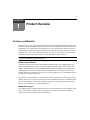
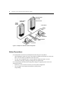
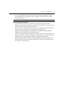
AutoView® Switch
For Technical Support:
Installer/User Guide
www.avocent.com/support
For models: 1415, 1515 and 2015
Avocent Corporation
4991 Corporate Drive
Huntsville, Alabama 35805-6201 USA
Tel: +1 256 430 4000
Fax: +1 256 430 4031
Avocent International Ltd.
Avocent House, Shannon Free Zone
Shannon, County Clare, Ireland
Tel: +353 61 715 292
Fax: +353 61 471 871
Avocent Asia Pacific
Singapore Branch Office
100 Tras Street, #15-01
Amara Corporate Tower
Singapore 079027
Tel: +656 227 3773
Fax: +656 223 9155
Avocent Germany
Gottlieb-Daimler-Straße 2-4
D-33803 Steinhagen
Germany
Tel: +49 5204 9134 0
Fax: +49 5204 9134 99
Avocent Canada
20 Mural Street, Unit 5
Richmond Hill, Ontario
L4B 1K3 Canada
Tel: +1 877 992 9239
Fax: +1 877 524 2985
590-644-616A
USA Notification
Warning: Changes or modifications to this unit not expressly approved by the party responsible for compliance
could void the user’s authority to operate the equipment.
Note: This equipment has been tested and found to comply with the limits for a Class A digital device, pursuant to
Part 15 of the FCC Rules. These limits are designed to provide reasonable protection against harmful interference
when the equipment is operated in a commercial environment. This equipment generates, uses and can radiate
radio frequency energy and, if not installed and used in accordance with the instruction manual, may cause
harmful interference to radio communications. Operation of this equipment in a residential area is likely to cause
harmful interference in which case the user will be required to correct the interference at his own expense.
Canadian Notification
This digital apparatus does not exceed the Class A limits for radio noise emissions from digital apparatus set
out in the Radio Interference Regulations of the Canadian Department of Communications.
Le présent appareil numérique n’émet pas de bruits radioélectriques dépassant les limites applicables aux
appareils numériques de la classe A prescrites dans le Règlement sur le brouillage radioélectrique édicté par le
Ministère des Communications du Canada.
Japanese Approvals
Korean Approvals
Safety and EMC Approvals and Markings
UL, FCC Class A, cUL, ICES Class A, CE, GS, IRAM, GOST, VCCI Class A, MIC Class A, C-Tick
AutoView® Switch
1415/1515/2015
Installer/User Guide
Avocent, the Avocent logo, The Power of Being There, AutoView,
OutLook and OSCAR are registered trademarks of Avocent Corporation
or its affiliates. All other marks are the property of their respective owners.
© 2007 Avocent Corporation. All rights reserved. 590-644-501C
Instructions
This symbol is intended to alert the user to the presence of important operating and maintenance
(servicing) instructions in the literature accompanying the appliance.
Dangerous Voltage
This symbol is intended to alert the user to the presence of uninsulated dangerous voltage within the
product’s enclosure that may be of sufficient magnitude to constitute a risk of electric shock to persons.
Power On
This symbol indicates the principal on/off switch is in the on position.
Power Off
This symbol indicates the principal on/off switch is in the off position.
Protective Grounding Terminal
This symbol indicates a terminal which must be connected to earth ground prior to making any other
connections to the equipment.
v
TABL E OF CONTEN TS
Table of Contents
List of Figures ................................................................................................................ vii
List of Tables ................................................................................................................... ix
Chapter 1: Product Overview.......................................................................................... 1
Features and Benefits ........................................................................................................................ 1
Safety Precautions ............................................................................................................................. 4
Chapter 2: Installation ..................................................................................................... 7
Getting Started ................................................................................................................................... 7
Supplied with the AutoView switch............................................................................................. 7
Rack Mounting Your AutoView Switch .............................................................................................. 7
Installing the AutoView Switch .......................................................................................................... 8
Connecting Users............................................................................................................................. 10
Cascading AutoView Switches......................................................................................................... 10
Adding Legacy Switches .................................................................................................................. 12
Setting Up Your AutoView Switching System .................................................................................. 15
Chapter 3: Basic Operations......................................................................................... 17
Controlling Your System at the Analog Ports.................................................................................. 17
Viewing and Selecting Ports and Servers ........................................................................................ 17
Navigating the OSCAR Interface ..................................................................................................... 19
Configuring OSCAR Interface Menus ............................................................................................. 21
Assigning server names ............................................................................................................ 22
Assigning device types .............................................................................................................. 24
Changing the display behavior................................................................................................. 25
Setting the keyboard country code............................................................................................ 26
Selecting a language................................................................................................................. 27
Controlling the status flag ........................................................................................................ 28
Setting console security ............................................................................................................ 29
Displaying Version Information ...................................................................................................... 33
Scanning Your System...................................................................................................................... 35
Running System Diagnostics............................................................................................................ 37
Broadcasting to Servers................................................................................................................... 39
vi
AutoView 1415/1515/2015 Switch Installer/User Guide
Changing Your Switch Mode ........................................................................................................... 41
Chapter 4: Advanced Operations ................................................................................. 43
Using Administrator Privileges ....................................................................................................... 43
Appendices..................................................................................................................... 47
Appendix A: Flash Upgrades........................................................................................................... 47
Appendix B: Technical Specifications ............................................................................................. 50
Appendix C: Sun Advanced Key Emulation..................................................................................... 52
Appendix D: Technical Support....................................................................................................... 54
vii
L IS T O F F IG URE S
List of Figures
Figure 1.1: Example of an AutoView Switch Configuration ............................................................. 4
Figure 2.1: AutoView Switch Horizontal Installation ...................................................................... 8
Figure 2.2: Basic AutoView Switch Configuration .......................................................................... 9
Figure 2.3: AutoView 2015 Switch Configuration with a Cascaded Switch .................................. 12
Figure 2.4: AutoView 2015 Switch Configuration with Legacy KVM Switches ............................ 13
Figure 2.5: AutoView Switch Configuration with AutoView 1415/1515/2015 Switches................. 14
Figure 3.1: Example of Configured Main Dialog Box .................................................................... 17
Figure 3.2: Setup Dialog Box (User)............................................................................................... 22
Figure 3.3: Setup Dialog Box (Admin) ............................................................................................ 22
Figure 3.4: Names Dialog Box ........................................................................................................ 23
Figure 3.5: Name Modify Dialog Box ............................................................................................. 23
Figure 3.6: Devices Dialog Box ...................................................................................................... 24
Figure 3.7: Device Modify Dialog Box ........................................................................................... 25
Figure 3.8: Menu Dialog Box.......................................................................................................... 25
Figure 3.9: Keyboard Box ............................................................................................................... 27
Figure 3.10: Keyboard Warning Dialog Box .................................................................................. 27
Figure 3.11: Language Dialog Box ................................................................................................. 28
Figure 3.12: Flag Dialog Box ......................................................................................................... 29
Figure 3.13: Set Position Flag ........................................................................................................ 29
Figure 3.14: Security Dialog Box.................................................................................................... 30
Figure 3.15: Version Dialog Box .................................................................................................... 33
Figure 3.16: Target Selection Dialog Box (Admin) ........................................................................ 34
Figure 3.17: Target Version Dialog Box........................................................................................ 34
Figure 3.18: Firmware Warning Dialog Box .................................................................................. 35
Figure 3.19: Scan Dialog Box ......................................................................................................... 36
Figure 3.20: Commands Dialog Box ............................................................................................... 37
Figure 3.21: Diagnostics Dialog Box.............................................................................................. 38
Figure 3.22: Diagnostics Warning Dialog Box............................................................................... 39
Figure 3.23: Broadcast Dialog Box ................................................................................................ 40
Figure 3.24: Broadcast Enable Confirm/Deny Dialog Box ............................................................ 41
Figure 3.25: Switch Dialog Box ...................................................................................................... 42
Figure 4.1: Security Menu ............................................................................................................... 43
viii
AutoView 1415/1515/2015 Switch Installer/User Guide
Figure 4.2: User Setup Menu (Administrator Only)........................................................................ 44
Figure 4.3: User Edit Menu (Administrator Only).......................................................................... 45
Figure 4.4: User Access Menu (Administrator Only)...................................................................... 45
Figure A.1: AVRIQ Status Dialog Box ............................................................................................ 48
Figure A.2: AVRIQ Upgrade Dialog Box........................................................................................ 49
ix
L I S T OF T A B L ES
List of Tables
Table 2.1: Legacy Switch Support ................................................................................................... 12
Table 3.1: OSCAR Interface Status Symbols ................................................................................... 18
Table 3.2: OSCAR Interface Navigation Basics ............................................................................. 19
Table 3.3: Setup Features to Manage Routine Tasks for Your Servers........................................... 21
Table 3.4: OSCAR Interface Status Flags ...................................................................................... 28
Table 3.5: Diagnostic Test Details ................................................................................................. 38
Table B.1: Product Specifications .................................................................................................. 50
Table C.1: Sun Key Emulation ........................................................................................................ 52
Table C.2: PS/2-to-USB Keyboard Mappings ................................................................................. 53
x
AutoView 1415/1515/2015 Switch Installer/User Guide
1
CHA PTER
1
Product Overview
Features and Benefits
The AutoView® 1415/1515/2015 switches integrate Avocent field-proven analog keyboard, video
and mouse (KVM) switching technology with advanced cable management, flexible access for two
simultaneous users, USB support and a patented, easy-to-use interface. This AutoView series of
KVM switches conveniently supports all major server platforms and features powerful on-screen
management for easy system configuration and server selection. The AutoView 1415/1515/2015
switches also feature user peripheral ports for PS/2 and USB keyboards and mice.
NOTE: With the exception of USB capability, all references to AutoView 1415/1515/2015 switches are applicable
to AutoView 1400/1500/2000 switches respectively.
AVRIQ Intelligent Module
A benefit of the AutoView switch is the AVRIQ intelligent module. The AVRIQ module with
CAT 5 design dramatically reduces cable clutter, while providing optimal resolution and video
settings. The built-in memory of the AVRIQ module simplifies configuration by assigning and
retaining unique server names and Electronic ID (EID) numbers for each attached server. The
AVRIQ module is powered directly from the server and provides Keep Alive functionality even if
the AutoView switch is not powered.
Each AutoView 2015 switch has 16 Avocent Rack Interface (ARI) ports for connecting AVRIQ
modules. AutoView 1415 and 1515 switches provide eight ARI ports. Utilizing an AVRIQ module,
you can attach additional switches to expand your AutoView switching system. This flexibility
allows you to add capacity as your data center grows.
Multiplatform support
The AVRIQ modules available with the AutoView switch support PS/2, Sun™, USB and serial
server environments. Using the OSCAR® graphical user interface in conjunction with these
modules allows you to switch easily across platforms.
2
AutoView 1415/1515/2015 Switch Installer/User Guide
Two-User Share Mode
The AutoView 1415/1515/2015 switches feature a Share Mode function that allows two users to
gain access to a primary server. The user configurable time-out feature allows you to determine the
amount of time (up to 600 seconds) for the target to remain idle before the other user can take
control of the target.
OSCAR graphical user interface
AutoView switches use the OSCAR interface, which features intuitive menus to configure your
switching system and select servers. servers can be identified by unique name, EID or port number,
allowing you to assign unique server names.
Security
The OSCAR interface allows you to protect your system with a screen saver password. After a
user-defined time, the screen saver mode engages and access is prohibited until the appropriate
password is entered to reactivate the system.
Operation modes
The OSCAR user interface provides convenient operation modes for easy system administration of
the AutoView switch. These modes (Broadcast, Scan, Switch and Share) allow you to manage your
switching activities. Chapter 3 explains these modes in detail.
Video
The AutoView switch provides optimal resolution for analog VGA, SVGA and XGA video.
Achieve resolutions of up to 1600 x 1200 @ 75Hz with a 100 foot (30 meter) cable.
NOTE: Resolutions above 1280 x 1024 may need to be manually set in the operating systems display settings.
Video resolution and distance is subject to cable quality and environmental factors.
Plug and Play
The AutoView switch also supports Display Data Channel (DDC) Plug and Play, which automates
configuration of the monitor and is compliant with the VESA DDC2B standard.
Flash upgradable
Upgrade your firmware at any time through a simple update utility to ensure that your AutoView
switching system is always running the most current version available. Both the AutoView switch
and the AVRIQ modules are Flash upgradable. See Appendix A for more information.
NOTE: Firmware available for the AutoView 1415/1515/2015 switch is also compatible with the AutoView 1400/
1500/2000 switch, but it is not compatible the AutoView 2020/2030 switch.
Chapter 1: Product Overview
3
Cascading expansion
Each AutoView switch supports up to 16 directly attached servers and can conveniently scale to
support more. You can expand your system using cascadable Avocent products such as other
AutoView or OutLook® switches. This extra “cascade” of units allows you to attach up to 256
servers in one system. See Chapter 2 for more information.
Local user accounts
The AutoView 1415/1515/2015 switches enable an administrator to configure up to four user
accounts for use with the switch. These user accounts allow the administrator to restrict what ports
a class of user can access, as well as the name of the user account and password. See Chapter 4 for
more information.
Integrated Access Cables
The AutoView 1415/1515/2015 switches also feature Integrated Access Cable (IAC) modules
designed to provide the same ease of use as the AVRIQ module. Available in three different
lengths, IAC modules are RJ-45 style cables that provide a reduced cost alternative to AVRIQ
modules. IAC modules support PS/2 and USB connectivity. Contact your Avocent representative
for more information.
NOTE: IAC modules are not upgradable.
4
AutoView 1415/1515/2015 Switch Installer/User Guide
AutoView Switch
(Cascaded)
Legacy Switch
(Cascaded)
Rack of Servers
AVRIQ
or IAC
Module
Critical Server
Analog
Connection
AutoView Switch
(Main)
Analog
Connection
Figure 1.1: Example of an AutoView Switch Configuration
Safety Precautions
To avoid potential video and/or keyboard problems when using Avocent products:
•
Ιf the building has 3-phase AC power, ensure that the computers and monitors are on the same
phase. For best results, they should be on the same circuit.
•
Use only Avocent-supplied cable to connect computers and KVM switches. Avocent
warranties do not apply to damage resulting from user-supplied cable.
To avoid potentially fatal shock hazard and possible damage to equipment, please observe the
following precautions:
•
Do not use a 2-wire extension cord in any Avocent product configuration.
•
Test AC outlets at the computer and monitor for proper polarity
and grounding.
Chapter 1: Product Overview
•
5
Use only with grounded outlets at both the computer and monitor. When using a backup
Uninterruptible Power Supply (UPS), power the computer, the monitor and the AutoView
switch off the supply.
NOTE: The AC inlet is the main disconnect.
Rack mount safety considerations
•
Elevated Ambient Temperature: If installed in a closed rack assembly, the operation
temperature of the rack environment may be greater than room ambient. Use care not to exceed
the rated maximum ambient temperature of the unit.
•
Reduced Air Flow: Installation of the equipment in a rack should be such that the amount of
airflow required for safe operation of the equipment is not compromised.
•
Mechanical Loading: Mounting of the equipment in the rack should be such that a hazardous
condition is not achieved due to uneven mechanical loading.
•
Circuit Overloading: Consideration should be given to the connection of the equipment to the
supply circuit and the effect that overloading of circuits might have on overcurrent protection
and supply wiring. Consider equipment nameplate ratings for maximum current.
•
Reliable Earthing: Reliable earthing of rack mounted equipment should be maintained. Pay
particular attention to supply connections other than direct connections to the branch circuit
(for example, use of power strips).
6
AutoView 1415/1515/2015 Switch Installer/User Guide
7
CHA PTER
2
Installation
Getting Started
Before installing your AutoView switch, refer to the following list to ensure you have all items that
shipped with the AutoView switch, as well as other items necessary for proper installation.
Supplied with the AutoView switch
•
Power cord
•
One null modem serial cable
•
Rack mounting kit
•
AutoView 1415/1515/2015 Installer/User Guide
•
AutoView 1415/1515/2015 Quick Installation Guide
Additional items needed
One IAC or AVRIQ module and CAT 5 cabling per attached server or switch
Rack Mounting Your AutoView Switch
Your AutoView switch may be rack mounted using the brackets supplied in your rack mounting kit.
Before installing the switch and other components in the rack cabinet (if not already installed),
stabilize the rack in a permanent location. Install your equipment starting at the bottom of the rack
cabinet, then work to the top.
8
AutoView 1415/1515/2015 Switch Installer/User Guide
Figure 2.1: AutoView Switch Horizontal Installation
CAUTION: Rack Loading - Overloading or uneven loading of racks may result in shelf or rack failure, causing
damage to equipment and possible personal injury. Do not exceed your rack load rating.
To install the 1U switch mounting bracket:
1.
Remove the first two screws on each side of the switch.
2.
Line up the holes in the “long side” of the kit’s side brackets with the screw holes in the switch.
3.
With a Phillips screwdriver, fasten the mounting brackets to the switch using two screws on
each side.
4.
Attach four cage nuts or clip nuts to the rack mounting flange of the rack cabinet so that the nut
is positioned on the inside of the rack.
NOTE: Nuts are not included with the rack mount kit.
5.
Mount the switch assembly to the rack cabinet by matching the holes in the “short side” of
each bracket to an appropriate set of matching holes on your rack cabinet.
6.
Next, insert the combination hex head screws through the slots in the bracket and the holes in
the mounting rail, then into the cage nuts or clip nuts.
Installing the AutoView Switch
Plug the supplied power cord into the back of the appliance and then into an appropriate power
source. Figure 2.2 illustrates one possible configuration for your AutoView switch. See the following
detailed set of procedures to successfully install your appliance.
Chapter 2: Installation
CAUTION: To reduce the risk of electric shock or damage to your equipment - Do not disable the power cord grounding plug. The grounding plug is an important safety feature.
- Plug the power cord into a grounded (earthed) outlet that is easily accessible at all times.
- Disconnect the power from the unit by unplugging the power cord from either the electrical outlet or the unit.
Analog User B
Configuration Port
(for updating firmware)
AutoView Switch
Servers 2-16
Analog User A
IAC Module
AVRIQ Module
Server 1
Figure 2.2: Basic AutoView Switch Configuration
NOTE: Only the AutoView 1515 and the AutoView 2015 switches support two simultaneous users.
9
10
AutoView 1415/1515/2015 Switch Installer/User Guide
To connect a server using an AVRIQ module:
1.
Locate the AVRIQ modules for your AutoView switch.
2.
Attach the appropriately color-coded cable ends to the keyboard, monitor and mouse ports on the
first server you will be connecting to the appliance.
3.
Attach one end of a CAT 5 cable to the RJ-45 connector on the AVRIQ module.
4.
Connect the other end of the CAT 5 cable to the desired ARI port on the back of your
AutoView switch.
5.
Repeat steps 2 through 4 for each server you wish to attach.
NOTE: When connecting a Sun AVRIQ module, you must use a multi-sync monitor to accommodate Sun
computers that support both VGA and sync-on-green or composite sync.
To connect a server using an IAC module:
1.
Locate an IAC module for the server you wish to connect.
2.
Attach the appropriately color-coded cable ends of the IAC module to the keyboard, monitor and
mouse ports on the server you will be connecting to the switch.
3.
Attach the other end of the IAC module to an open ARI port.
4.
Repeat steps 1 through 3 for each server you wish to attach.
Connecting Users
To connect local peripherals:
1.
Select the keyboard, monitor and mouse to be connected to local analog user A.
2.
Locate the port set labeled A on the back of the appliance. Connect these peripherals to their
respective ports.
3.
Bundle and label the cables for easy identification.
4.
Repeat these steps for user B, if desired.
Cascading AutoView Switches
You can cascade multiple AutoView 1415/1515/2015 switches to enable one or two users to
connect to as many as 256 servers. In a cascaded system, each ARI (Avocent Rack Interface) port
on the main AutoView switch will connect to the ACI (Avocent Console Interface) port on each
cascaded AutoView switch. Each cascaded switch can then be connected to a server with an
AVRIQ module or IAC. The example shown in Figure 2.3 shows one AutoView switch cascaded
under the main switch, enabling the connection of up to 15 primary servers and 16 secondary
servers. Using this configuration, you could cascade 16 AutoView switches under the main switch,
enabling the connection of up to 256 servers. Only one level of tiering is supported in this type of
configuration, which means you cannot cascade any additional legacy switches or another
AutoView switch.
Chapter 2: Installation
11
In this configuration, the local port OSCAR interface is disabled in switches cascaded below the
main AutoView switch.
To cascade multiple AutoView switches:
1.
Connect the cascaded AutoView switch to each server as described in the previous Installing
the AutoView Switch section.
2.
Connect the local peripherals to analog user A and/or B of the main switch as described in To
connect local peripherals.
3.
Attach one end of the CAT 5 cabling that will run between your main and cascaded AutoView
switch to the RJ-45 ACI port on the cascaded AutoView switch.
4.
Attach the other end of the CAT 5 cable to one of the RJ-45 ARI ports on the main
AutoView switch.
NOTE: The system will automatically “merge” the two switches together as one. All servers connected to the
cascaded AutoView switch will display on the main AutoView switch server list in the OSCAR interface.
5.
Repeat steps 3 and 4 for all additional (secondary) cascaded AutoView switches you wish
to attach.
12
AutoView 1415/1515/2015 Switch Installer/User Guide
Analog User A
Analog User B
AutoView 2015 Switch
ARI Ports
15 Primary
Servers
AutoView 2015 Switch (cascaded)
ACI Port
16 Secondary
Servers
Figure 2.3: AutoView 2015 Switch Configuration with a Cascaded Switch
Adding Legacy Switches
You can add legacy switches to the AutoView switching system for easy integration into your
existing configuration. In a cascaded system, each ARI port will accommodate up to 24 servers.
See the following table for legacy switches compatible with the AutoView switching system.
Table 2.1: Legacy Switch Support
Legacy Product
Model Numbers
OutLook ES switch
140ES, 180ES, 280ES, 1160ES, 2160ES, 4160ES
AutoView switch
AV200-4, AV200-8, AV400-4, AV400-8, AV416, AV424, AV1415, AV1515, AV2015
Chapter 2: Installation
Local Analog User A
AutoView 2015 Switch
AVRIQ Module
PS/2, USB, Sun and serial
cables are available
OutLook ES Switch
Server 1
AVRIQ Module
AutoView 200/400 Switch
Server 2
Figure 2.4: AutoView 2015 Switch Configuration with Legacy KVM Switches
13
14
AutoView 1415/1515/2015 Switch Installer/User Guide
Local Analog User A
Local Analog User B
AutoView 1415/1515/2015 Switch
Secondary
Servers
AVRIQ Module
PS/2, USB, Sun and serial
modules are available
AutoView 1415/1515/2015 Switch
Secondary
Servers
Figure 2.5: AutoView Switch Configuration with AutoView 1415/1515/2015 Switches
NOTE: The PS2IAC modules can be utilized in Figure 2.5.
Chapter 2: Installation
15
To add a legacy KVM switch:
1.
Mount the primary KVM switch into your rack cabinet.
2.
Connect one end of a CAT 5 cable to an available port on the back of your AutoView switch.
3.
Attach the keyboard, monitor and mouse connectors of the AVRIQ module to a user port on
your cascaded switch.
4.
Attach the other end of the CAT 5 cabling to the RJ-45 connector on the AVRIQ module.
5.
Connect the servers to your cascaded switch according to the instructions included with
the switch.
6.
Power cycle the cascaded switch to enable its local user port to recognize the AVRIQ module.
7.
Repeat steps 2 to 6 for all cascaded switches you wish to attach to your system.
To connect local peripherals:
1.
Select the keyboard, monitor and mouse to be connected to local user A.
2.
Locate the port set labeled A on the back of the switch. Connect these peripherals to their
respective ports.
3.
For the multiuser, 16-port AutoView switch, repeat steps 1 and 2 for the local analog port set
labeled B.
- or For the AutoView 1415/1515 switch, proceed to step 4.
4.
Bundle and label the cables for easy identification.
Setting Up Your AutoView Switching System
The AutoView switching system enables you to auto detect and configure each port on your
appliance. Chapter 3 provides detailed instructions on name customization and OSCAR interface
setup and configuration.
16
AutoView 1415/1515/2015 Switch Installer/User Guide
17
CHA PTER
3
Basic Operations
Controlling Your System at the Analog Ports
The AutoView switch features one or two analog port sets on the back of the switch that allow you
to connect a monitor and a PS/2 or USB keyboard and mouse for direct analog access. The
AutoView switch uses the OSCAR interface, featuring intuitive menus to configure your system
and select servers.
Viewing and Selecting Ports and Servers
Use the OSCAR interface Main dialog box to view, configure and control servers in the AutoView
switching system. View your servers by name, port or by the unique Electronic ID number (EID)
embedded in each AVRIQ module and IAC. You will see an OSCAR interface-generated port list
by default when you first launch the OSCAR GUI.
The Port column indicates the ARI port to which a server is connected. If you connect a legacy KVM
switch to the main AutoView switch or a cascaded AutoView switch, the port numbering displays
the ARI port first, then the switch port to which the server is connected. For example, in Figure 3.1,
servers 04-03 and 01-02 are connected to switches, then to servers on ports 03 and 02 respectively.
To access the Main dialog box:
Press Print Screen to launch the OSCAR interface. The Main dialog box displays.
Figure 3.1: Example of Configured Main Dialog Box
18
AutoView 1415/1515/2015 Switch Installer/User Guide
NOTE: You can also press the Control key twice, the Alt key twice or the Shift key twice within one second to
launch the OSCAR interface. See Changing the display behavior later in this chapter for further details. You
can use this key sequence in any place you see Print Screen throughout this installer/user guide.
Viewing the status of your switch
The status of the servers in your system is indicated in the right columns of the Main dialog box.
The following table describes the status symbols.
Table 3.1: OSCAR Interface Status Symbols
Symbol
Description
AVRIQ modules and IACs are online (green circle).
AVRIQ modules and IACs are offline or are not operating properly.
Server is cascaded through a cascade legacy switch. The switch is online and has power.
Server is cascaded through a cascade legacy switch. The switch is offline or has no power.
AVRIQ module is being upgraded (yellow circle).
AVRIQ modules and IACs are being accessed by the indicated user channel (green
channel letter).
AVRIQ modules and IACs are blocked by the indicated user channel (black channel letter).
Selecting servers
Use the Main dialog box to select servers. When you select a server, the switch reconfigures the
keyboard and mouse to the proper settings for that server.
To select servers:
Double-click the server name, EID or port number.
-orIf the display order of your server list is by port (Port button is depressed), type the port number
and press Enter.
-orIf the display order of your server list is by name or EID number (Name or EID button is
depressed), type the first few characters of the name of the server or the EID number to establish it
as unique and press Enter.
Chapter 3: Basic Operations
19
To select the previous server:
Press Print Screen and then Backspace. This key combination toggles you between the previous
and current connections.
To disconnect the user from a server:
Press Print Screen and then Alt+0. This leaves the user in a free state, with no server selected. The
status flag on your desktop displays Free.
Soft switching
Soft switching is the ability to switch servers using a hotkey sequence. You can soft switch to a server by
pressing Print Screen and then typing the first few characters of its name or number. If you have set a
Screen Delay Time and you press the key sequences before that time has elapsed, the OSCAR interface
will not display.
To configure servers for soft switching:
1.
Press Print Screen to launch the OSCAR interface. The Main dialog box displays.
2.
Click Setup - Menu. The Menu dialog box displays.
3.
For Screen Delay Time, type the number of seconds of delay desired before the Main dialog
box is displayed after Print Screen is pressed.
4.
Click OK.
To soft switch to a server:
1.
To select a server, press Print Screen. If the display order of your server list is by port (Port
button is depressed), type the port number and press Enter.
-orIf the display order of your server list is by name or EID number (Name or EID button is
depressed), type the first few characters of the name of the server or the EID number to
establish it as unique and press Enter.
2.
To switch back to the previous server, press Print Screen then Backspace.
Navigating the OSCAR Interface
This table describes how to navigate the OSCAR interface using the keyboard and mouse.
Table 3.2: OSCAR Interface Navigation Basics
This Keystroke
Does This
Print Screen,Ctrl-Ctrl
Shift-Shift, and/or
Alt-Alt
Activates the OSCAR interface. See Changing the display behavior later in this
chapter for further details.
Print Screen-Print
Screen
Press Print Screen twice to send the Print Screen keystroke to the currently
selected device.
20
AutoView 1415/1515/2015 Switch Installer/User Guide
Table 3.2: OSCAR Interface Navigation Basics (Continued)
This Keystroke
Does This
F1
Opens the Help screen for the current dialog box.
Escape
Closes the current dialog box without saving changes and returns to the previous
one. In the Main dialog box, it closes the OSCAR interface and returns to the flag. In
a message box, it closes the pop-up box and returns to the current dialog box.
Alt+Hotkey
Opens dialog boxes, selects or checks options and executes actions when used with
underlined or other designated letters.
Alt+X
Closes the current dialog box and returns to the previous one.
Alt+O
Selects the OK button, then returns to the previous dialog box.
Single-click, Enter
In a text box, selects the text for editing and enables the Left and Right Arrow keys
to move the cursor. Press Enter again to quit the edit mode.
Enter
Completes a switch in the Main dialog box and exits the OSCAR interface.
Print Screen,
Backspace
Toggles back to previous selection.
Print Screen, Alt+0
(zero)
Immediately disengages a user from a server; no server is selected. Status flag
displays Free. (This only applies to the 0 on the keyboard and not the keypad.)
Print Screen, Pause
Immediately turns on screen saver mode and prevents access to that specific
console, if it is password protected.
Up/Down Arrows
Moves the cursor from line to line in lists.
Right/Left Arrows
Moves the cursor between columns. When editing a text box, these keys move the
cursor within the column.
Page Up/Page Down
Pages up and down through Name and Port lists and Help pages.
Home/End
Moves the cursor to the top or bottom of a list.
Delete
Deletes characters in a text box.
Page Up/Page Down
Pages up and down through Name and Port lists and Help pages.
Numbers
Type from the keyboard or keypad.
Print Screen, Ctrl+ F4
Logs the current user out of the switch (only available when Enable Local User
Accounts is checked on the Security screen).
Chapter 3: Basic Operations
21
Configuring OSCAR Interface Menus
You can configure your AutoView switch from the Setup menu within the OSCAR interface. Select
the Names button when initially setting up your switch to identify servers by unique names. Select the
other setup features to manage routine tasks for your servers from the OSCAR interface menu.
Table 3.3: Setup Features to Manage Routine Tasks for Your Servers
Feature
Purpose
Menu
Change the server listing between numerically by port or EID number and
alphabetically by name. Change the Screen Delay Time before the OSCAR interface
displays after pressing Print Screen.
Flag
Change display, timing, color or location of the status flag.
Broadcast
Set up to simultaneously control multiple servers through keyboard and
mouse actions.
Scan
Set up a custom scan pattern for up to 16 servers.
Security
Set passwords to restrict server access. Enable the screen saver.
Devices
Identify the appropriate number of ports on an attached cascaded switch.
Names
Identify servers by unique names.
Switch
Choose the Switch Mode and the Share Mode time-out.
Keyboard
Choose the keyboard country code that is sent to the AVRIQ module and IAC.
Language
Choose the language supported by the OSD. Change the OSD text language.
User
Allows the administrator to set up the Local User Accounts (only visible when Enable
Local User Accounts is checked on the Security screen).
NOTE: Please note that the administrative user’s name is case sensitive. You must log in as Admin to utilize
administrative functions.
Only the Menu, Flag and Security screens are available to the users without administrator privileges. All other
screens, except the User screen, are available to the administrator when Enable Local User Accounts is disabled
in the Security screen.
To access the Setup menu:
1.
Press Print Screen to launch the OSCAR interface. The Main dialog box displays.
2.
Click Setup. The Setup dialog box displays.
22
AutoView 1415/1515/2015 Switch Installer/User Guide
Figure 3.2: Setup Dialog Box (User)
Figure 3.3: Setup Dialog Box (Admin)
NOTE: Figure 3.3 displays for the Administrator if Local User Accounts are enabled, or for all user if Local User
Accounts are disabled.
Assigning server names
Use the Names dialog box to identify individual servers by name rather than by port number. The
Names list is always sorted by port order. Names are stored in the AVRIQ or IAC module, so even
if you move the module/cable to another ARI port, the name and configuration will be recognized
by the switch.
NOTE: If a server is turned off, its respective AVRIQ or IAC module will not appear in the Names list.
To access the Names dialog box:
1.
Press Print Screen to launch the OSCAR interface. The Main dialog box will appear.
2.
Click Setup - Names. The Names dialog box displays.
Chapter 3: Basic Operations
23
Figure 3.4: Names Dialog Box
NOTE: If the server list changes, the mouse cursor will turn into an hourglass as the list is automatically updated. No
mouse or keyboard input will be accepted until the list update is complete.
To assign names to servers:
1.
In the Names dialog box, select a server name or port number and click Modify. The Name
Modify dialog box displays.
Figure 3.5: Name Modify Dialog Box
2.
Type a name in the New Name box. Names of servers may be up to 15 characters long. Supported
characters include: A to Z, a to z, 0 to 9, space and hyphen.
3.
Click OK to transfer the new name to the Names dialog box. Your selection is not saved until
you click OK in the Names dialog box.
4.
Repeat steps 1 to 3 for each server in the system.
5.
Click OK in the Names dialog box to save your changes.
-orClick X or press Escape to exit the dialog box without saving changes.
24
AutoView 1415/1515/2015 Switch Installer/User Guide
NOTE: If an AVRIQ module has not been assigned a name, the EID is used as the default name.
Assigning device types
The AutoView switch automatically discovers cascaded KVM switches, but you will need to specify
the number of ports on the cascaded switch through the Devices dialog box. You will see an Sw-8 or
Sw-24 display in the Type category for the cascaded switch. Select the switch from the list and the
Modify button displays, allowing you to assign it the appropriate number of ports.
NOTE: The Modify button will only be available if a configurable switch is selected.
To access the Devices dialog box:
1. Press Print Screen to launch the OSCAR interface. The Main dialog box will appear.
2. Click Setup - Devices. The Devices dialog box displays.
Figure 3.6: Devices Dialog Box
When the AutoView switch discovers a cascaded switch, you will notice the port numbering
change to accommodate each server under that switch. For example, if the switch is connected to
ARI port 6, the switch port would be listed as 06 and each server under it would be numbered
sequentially 06-01, 06-02 and so on.
To assign a device type:
1.
In the Devices dialog box, select the desired port number.
2.
Click Modify. The Device Modify dialog box displays.
Chapter 3: Basic Operations
25
Figure 3.7: Device Modify Dialog Box
3.
Choose the number of ports supported by your cascaded switch and click OK. If the number of
desired ports is not listed, click Other and type in port number between 4 and 24 ports.
4.
Repeat steps 1 to 3 for each port requiring a device type to be assigned.
5.
Click OK in the Devices dialog box to save settings.
NOTE: Changes made in the Device Modify dialog box are not saved until you click OK in the Devices
dialog box.
Changing the display behavior
Use the Menu dialog box to change the display order of servers, change the key sequence to launch
the OSCAR interface and set a Screen Delay Time for the OSCAR interface. The display order setting
alters how servers display in several screens including the Main, Devices and Broadcast dialog boxes.
To access the Menu dialog box:
1.
Press Print Screen to launch the OSCAR interface. The Main dialog box displays.
2.
Click Setup - Menu in the Main dialog box. The Menu dialog box displays.
Figure 3.8: Menu Dialog Box
26
AutoView 1415/1515/2015 Switch Installer/User Guide
To choose the default display order of servers:
1.
Select Name to display servers alphabetically by name.
-orSelect EID to display servers numerically by EID number.
-orSelect Port to display servers numerically by port number.
2.
Click OK.
To set up key sequences to launch the OSCAR interface:
1.
Click the box next to the key sequence you want to start the OSCAR interface. Unchecking all
boxes will leave Print Screen as the default.
2.
Click OK.
To set a Screen Delay Time for the OSCAR interface:
1.
Type in the number of seconds (0 to 9) to delay the OSCAR interface display after you press Print
Screen. Entering 0 will instantly launch the OSCAR interface with no delay.
2.
Click OK.
Setting a Screen Delay Time allows you to complete a soft switch without the OSCAR interface
displaying. To perform a soft switch, see Soft switching in this chapter.
Setting the keyboard country code
The AutoView 1415/1515/2015 switch can be configured to recognize a variety of keyboards. The
default setting is for a US keyboard. If you wish to change this configuration, the Keyboard dialog
box allows you to select a different keyboard country code.
NOTE: Ensure that the country code selected on your Sun server matches the Keyboard Country Code selected
in the OSCAR interface or your keyboard will not be mapped correctly.
Chapter 3: Basic Operations
27
Figure 3.9: Keyboard Box
To change the keyboard country code:
1.
Press Print Screen to launch the OSCAR interface. The Main dialog box will appear.
2.
Click Setup-Keyboard. The Keyboard dialog box displays.
3.
Select your desired keyboard country code and click OK.
4.
A Keyboard Warning dialog box will appear to confirm your changes.
5.
Click OK for changes to take effect.
Figure 3.10: Keyboard Warning Dialog Box
Selecting a language
The Language dialog box allows you to select the language supported by the OSD and change the
OSD text to that language.
To select a language:
1.
Press Print Screen to launch the OSCAR interface. The Main dialog box will appear.
2.
Click Setup-Language. The Language dialog box displays.
28
AutoView 1415/1515/2015 Switch Installer/User Guide
3.
Select your desired language.
4.
Click OK for changes to take effect.
Figure 3.11: Language Dialog Box
Controlling the status flag
The status flag displays on your desktop and shows the name or EID number of the selected server
or the status of the selected port. Use the Flag dialog box to configure the flag to display by server
name or EID number, or to change the flag color, opacity, display time and location on the desktop.
Table 3.4: OSCAR Interface Status Flags
Flag
Description
Flag type by name
Flag type by EID number
Flag indicating that the user has been disconnected from all systems
Flag indicating that Broadcast Mode is enabled
To access the Flag dialog box:
1. Press Print Screen. The Main dialog box will appear.
2. Click Setup - Flag. The Flag dialog box displays.
Chapter 3: Basic Operations
29
Figure 3.12: Flag Dialog Box
To determine how the status flag is displayed:
1.
Select Name or EID to determine what information will be displayed.
2.
Select Displayed to show the flag all the time or select Timed to display the flag for only five
seconds after switching.
3.
Select a flag color in Display Color.
4.
In Display Mode, select Opaque for a solid color flag or select Transparent to see the desktop
through the flag.
5.
To position the status flag on the desktop:
a.
Click Set Position to gain access to the Set Position Flag screen.
b.
Left-click on the title bar and drag to the desired location.
c.
Right-click to return to the Flag dialog box.
Figure 3.13: Set Position Flag
NOTE: Changes made to the flag position are not saved until you click OK in the Flag dialog box.
6.
Click OK to save settings.
-orClick X to exit without saving changes.
Setting console security
The OSCAR interface enables you to set security on your analog port console. You can establish a
screen saver mode that engages after your console remains unused for a specified Inactivity Time.
30
AutoView 1415/1515/2015 Switch Installer/User Guide
Once engaged, your console will remain locked until you press any key or move the mouse. You
will then need to type in your password to continue.
Use the Security dialog box to lock your console with password protection, set or change your
password and enable the screen saver.
NOTE: If a password has been previously set, you will have to enter the password before you can access the
Security dialog box. If you should lose or forget your password, please contact Avocent Technical Support about
returning your switch for service. See Appendix D:Technical Support for contact information.
To access the Security dialog box:
1.
Press Print Screen to launch the OSCAR interface. The Main dialog box will appear.
2.
Click Setup - Security. The Security dialog box displays.
Figure 3.14: Security Dialog Box
NOTE: Figure 3.12 is the Security screen for the administrator and local user when the Enable User Accounts
feature is turned off. The restricted user can only access the Change Password function of this screen.
To set or change the password:
1.
Single-click and press Enter or double-click in the New text box.
2.
Type the new password in the New text box and press Enter.
Passwords must contain both alpha and numeric characters, are case sensitive and may be up to
12 characters long. Supported characters are: A to Z, a to z, 0 to 9, space and hyphen.
3.
In the Repeat box, type the password again and press Enter.
4.
Click OK to change only your password, and then close the dialog box.
To password protect your console:
1.
Set your password as described in the previous procedure.
2.
Select Enable Screen Saver.
Chapter 3: Basic Operations
31
3.
Type the number of minutes for Inactivity Time (from 1 to 99) to delay activation of password
protection and the screen saver feature.
4.
For Mode, select Energy if your monitor is ENERGY STAR® compliant; otherwise select Screen.
CAUTION: Monitor damage can result from the use of Energy mode with monitors not compliant with
ENERGY STAR.
5.
(Optional) Click Test to activate the screen saver test which lasts 10 seconds then returns you to
the Security dialog box.
6.
Click OK.
To log in to your console:
1.
Press any key or move the mouse.
2.
The Password dialog box displays. Type your password, then click OK.
3.
The Main dialog box displays if the password was entered properly.
To remove password protection from your console:
1.
From the Main dialog box, click Setup - Security; the Password dialog box displays. Type your
password, then click OK.
2.
In the Security dialog box, single-click and press Enter or double-click in the New box. Leave
the box blank. Press Enter.
3.
Single-click and press Enter or double-click in the Repeat box. Leave the box blank.
Press Enter.
4.
Click OK to eliminate your password.
To enable local user accounts:
1.
Click the Enable Local User Accounts checkbox.
2.
Click OK. See Chapter 4 for more information on setting up local user accounts.
To disable local user accounts (Admin user only):
1.
Click Enable Local User Accounts to uncheck the box and disable this option.
2.
Click OK.
To enable the screen saver mode with no password protection:
1.
If your console does not require a password to gain access to the Security dialog box, proceed
to step 2.
-orIf your console is password protected, see the previous procedure, then go to step 2.
2.
Select Enable Screen Saver.
3.
Type the number of minutes for Inactivity Time (from 1 to 99) to delay activation of the
screen saver.
32
AutoView 1415/1515/2015 Switch Installer/User Guide
4.
Choose Energy if your monitor is ENERGY STAR compliant; otherwise select Screen.
CAUTION: Monitor damage can result from the use of Energy mode with monitors not compliant with
ENERGY STAR.
5.
(Optional) Click Test to activate the screen saver test which lasts 10 seconds then returns you
to the Security dialog box.
6.
Click OK.
NOTE: Activation of the screen saver mode disconnects the user from a server; no server is selected. The status
flag displays Free.
To exit the screen saver mode:
Press any key or move your mouse. The Main dialog box displays and any previous server
connection will be restored.
Chapter 3: Basic Operations
33
To turn off the screen saver:
1.
In the Security dialog box, clear Enable Screen Saver.
2.
Click OK.
To immediately turn on the screen saver:
Press Print Screen, then press Pause.
Displaying Version Information
The OSCAR interface enables you to display the versions of the AutoView switch, as well as the
AVRIQ module and IAC module firmware. For optimum performance, keep your firmware
current. For more information, see Appendix A.
To display version information:
1.
Press Print Screen. The Main dialog box will appear.
2.
Click Commands - Display Versions. The Version dialog box displays. The top half of the box
lists the subsystem versions in the appliance.
Figure 3.15: Version Dialog Box
3.
Click the Target button to view individual AVRIQ and IAC module version information. The
Target Selection dialog box displays.
34
AutoView 1415/1515/2015 Switch Installer/User Guide
Figure 3.16: Target Selection Dialog Box (Admin)
4.
Select an AVRIQ or IAC module to view and click the Version button. The Target Version
dialog box displays. For more information on loading firmware, see Appendix A.
Figure 3.17: Target Version Dialog Box
5.
Click the Load Firmware button to view the load firmware screen. The Load Firmware button
will not appear in the user version of the Target Selection Dialog Box.
NOTE: The Load Firmware button will only display for an AVRIQ module; IAC modules are not upgradable.
Only the administrator and the user (when local user accounts are disabled) can upgrade the firmware on an
AVRIQ module.
Chapter 3: Basic Operations
35
Figure 3.18: Firmware Warning Dialog Box
To decommission an AVRIQ module:
Decommissioning an AVRIQ module restores the factory defaults in Sun, USB and PS/2 AVRIQ
modules only.
1.
Press Print Screen. The Main dialog box will appear.
2.
Click Commands - Display Versions. The Version dialog box displays.
3.
Click the Target button to view individual AVRIQ module version information. The Target
Selection dialog box displays.
4.
Click the Decommission button.
5.
Click OK to to reset the AVRIQ module to factory default.
NOTE: Clicking OK in the Decommision screen will remove any assigned server names and will reset all
configurable items while leaving the EID setting intact.
6.
Click X to close the dialog box.
NOTE: The Load Firmware button will only display for an AVRIQ module; IAC modules are not upgradable.
Only the administrator and the user (when local user accounts are disabled) can upgrade the firmware on an
AVRIQ module.
Scanning Your System
In Scan Mode, the appliance automatically scans from port to port (server to server). You can scan
up to 16 servers, specifying which servers to scan and the number of seconds that each server will
display. The scanning order is determined by placement of the server in the list. The list is always
shown in scanning order. You can, however, choose to display the server’s name or EID number by
pressing the appropriate button.
36
AutoView 1415/1515/2015 Switch Installer/User Guide
To add servers to the scan list:
1.
If the OSCAR interface is not open, press Print Screen. The Main dialog box will appear.
2.
Click Setup - Scan. The Scan dialog box displays.
Figure 3.19: Scan Dialog Box
3.
The dialog box contains a listing of all servers attached to your appliance. Click the checkbox
next to the servers you wish to scan.
-orDouble-click on a server’s name or port.
-orPress Alt and the number of the server you wish to scan. You can select up to 16 servers from the
entire list.
4.
In the Scan Time box, type the number of seconds (from 3 to 99) of desired time before the
scan moves to the next server in the sequence.
5.
Click OK.
To remove a server from the scan list:
1.
In the Scan dialog box, deselect the checkbox next to the server to be removed.
-orDouble-click on the server’s name or port.
-orClick the Clear button to remove all servers from the scan list.
2.
Click OK.
To start the Scan Mode:
1.
If the OSCAR interface is not open, press Print Screen. The Main dialog box will appear.
2.
Click Commands. The Commands dialog box displays.
Chapter 3: Basic Operations
37
Figure 3.20: Commands Dialog Box
NOTE: Figure 3.17 shows the Commands screen for the administrator and local user when the Enable User
Accounts feature is turned off. The restricted user will only have access to the Display Versions, Device Reset
and Log Out buttons.
3.
Select Scan Enable in the Commands dialog box.
4.
Click X to close the Commands dialog box.
NOTE: Scanning will begin when the Main dialog box or flag is displayed. Scanning is inhibited in any other
OSCAR interface dialog box.
To cancel Scan Mode:
1.
Select a server if the OSCAR interface is open.
-orMove the mouse or press any key on the keyboard if the OSCAR interface is not open.
Scanning will stop at the currently selected server.
2.
Press Print Screen. The Main dialog box will appear.
3.
Click Commands. The Commands dialog box displays.
4.
Clear Scan Enable.
Running System Diagnostics
You can validate the integrity of your system through the Run Diagnostics command. This command
checks the main board functional sub-systems (memory, communications, switch control and the
video channels) for each system controller. When you select the Run Diagnostics option, you will
receive a warning indicating that all users (remote and local) will be disconnected. Click OK to
confirm and begin the test.
The Diagnostics dialog box displays. The top section of the dialog box displays the hardware tests.
The bottom portion divides the tested AVRIQ and IAC modules into three categories: On-line,
Offline or Suspect.
38
AutoView 1415/1515/2015 Switch Installer/User Guide
NOTE: AVRIQ or IAC modules may appear to be offline while being upgraded.
Figure 3.21: Diagnostics Dialog Box
Next to each item to be tested, you will see a pass (green circle) or fail (red x) symbol display to
the left of each item as that test finishes. The following table details each of the tests.
Table 3.5: Diagnostic Test Details
Test
Description
Memory Tests
Reports on the condition of the main board RAM
Firmware CRCs
Reports on the condition of the main board RAM
Comm Interfaces
Validates the current firmware images stored in the system’s Flash
Switch Controller test
Verifies the switch matrix controller is accessible and functional
Local Video
Indicates the condition of the local video monitor
On-line Targets
Indicates the total number of currently connected and powered targets
Offline Targets
Indicates the number of targets that have been connected successfully in the
past and are powered down
Suspect Targets
Indicates the number of targets that have been detected, but are either
unavailable for connection or have dropped packets during the ping tests
To run diagnostic tests:
1.
If the OSCAR interface is not open, press Print Screen. The Main dialog box will appear.
2.
Click Commands - Run Diagnostics. A warning message displays indicating that all users will
be disconnected.
Chapter 3: Basic Operations
39
Figure 3.22: Diagnostics Warning Dialog Box
3.
Click OK to begin diagnostics.
-orClick X or press Escape to exit the dialog box without running a diagnostic test.
4.
All users are disconnected and the Diagnostics dialog box displays.
5.
As each test is finished, a pass (green circle) or fail (red x) symbol displays. The test is complete when the last test’s symbol displays.
Broadcasting to Servers
The analog user can simultaneously control more than one server in a system to ensure that all
selected servers receive identical input. You can choose to broadcast keystrokes and/or mouse
movements independently.
NOTE: You can broadcast to up to 16 servers at a time, one server per ARI port.
To access the Broadcast dialog box:
1.
Press Print Screen. The Main dialog box will appear.
2.
Click Setup - Broadcast. The Broadcast dialog box displays.
40
AutoView 1415/1515/2015 Switch Installer/User Guide
Figure 3.23: Broadcast Dialog Box
NOTE: Broadcasting Keystrokes - The keyboard state must be identical for all servers receiving a broadcast to
interpret keystrokes identically. Specifically, the Caps Lock and Num Lock modes must be the same on all
keyboards. While the appliance attempts to send keystrokes to the selected servers simultaneously, some servers
may inhibit and thereby delay the transmission.
NOTE: Broadcasting Mouse Movements - For the mouse to work accurately, all systems must have identical
mouse drivers, desktops (such as identically placed icons) and video resolutions. In addition, the mouse must be
in exactly the same place on all screens. Because these conditions are extremely difficult to achieve,
broadcasting mouse movements to multiple systems may have unpredictable results.
To broadcast to selected servers:
1.
From the Broadcast dialog box, select the mouse and/or keyboard checkboxes for the servers
that are to receive the broadcast commands.
-orPress the Up or Down Arrow keys to move the cursor to the target server. Then press Alt+K to
select the keyboard checkbox and/or Alt+M to select the mouse checkbox. Repeat for
additional servers.
2.
Click OK to save the settings and return to the Setup dialog box. Click X or press Escape to
return to the Main dialog box.
3.
Click Commands. The Commands dialog box displays.
4.
Click the Broadcast Enable checkbox to activate broadcasting. The Broadcast Enable
Confirm/Deny dialog box displays.
Chapter 3: Basic Operations
41
Figure 3.24: Broadcast Enable Confirm/Deny Dialog Box
5.
Click OK to enable the broadcast. Click X or press Escape to cancel and return to the Commands dialog box.
6.
If broadcasting is enabled, type the information and/or perform the mouse movements you
want to broadcast from the switch. Only servers in the list are accessible.
NOTE: The other user is disabled when Broadcast Mode is enabled.
To turn broadcasting off:
From the Commands dialog box, clear the Broadcast Enable checkbox.
Changing Your Switch Mode
Your AutoView switch allows you to connect to attached servers using two methods: Preemptive
and Cooperative.
Select Preemptive (default setting) to allow any user to select any server at any time; a request from
another user disconnects the current user without warning.
-orSelect Cooperative to maintain the current user connection; the current user will not be
disconnected if another user requests connection.
To access the Switch dialog box:
1.
Press Print Screen. The Main dialog box will display.
2.
Click Setup - Switch. The Switch dialog box displays.
42
AutoView 1415/1515/2015 Switch Installer/User Guide
Figure 3.25: Switch Dialog Box
3.
Select either Preemptive or Cooperative as your Switch Mode.
4.
Click OK to save changes. Click X or press Escape to cancel.
Setting the Share Mode feature
The Share Mode feature of the AutoView 1415/1515/2015 switches allows two users to gain
access to a primary server.
To enable Share Mode:
1.
Press Print Screen. The Main dialog box will display.
2.
Click Setup - Switch. The Switch dialog box displays.
3.
Select Share Enable from the Switch dialog box.
4.
Choose the amount of inactivity time for the target (up to 600 seconds) before another user can
take control of the target.
5.
Click OK to save changes. Click X or press Escape to cancel.
43
CHA PTER
4
Advanced Operations
Using Administrator Privileges
The AutoView 1415/1515/2015 switches allow up to four users and one administrator to log into a
switch, with the administrator having the ability to restrict users from accessing the targets via the
Security menu. The administrator can edit, access and/or delete user accounts.
Figure 4.1: Security Menu
To access the User Setup screen (administrator only):
1.
Click the Enable User Account checkbox in the Security menu. The Setup menu will appear.
2.
Click the OK button.
3.
Click the User button on the Setup screen to enter the User Setup screen.
NOTE: Clicking the User button on the Setup screen will automatically log out any currently logged in user. Other
users will remain logged out until your changes are complete.
44
AutoView 1415/1515/2015 Switch Installer/User Guide
Figure 4.2: User Setup Menu (Administrator Only)
User Setup menu functions (administrator only)
The User Setup menu allows the administrator to edit, access and/or delete a user account. The
menu is only accessible if the Enable User Account checkbox is enabled in the Security menu. The
AutoView 1415/1515/2015 switches will have four standard user accounts, with the default names
of User1, User2, User3 and User4.
To edit a user:
1.
Click the username of the user to be modified.
2.
Click Edit to change the username and/or password of the selected user.
3.
Click Access to restrict port access for the selected user.
4.
Click Delete to restore the selected user to the default state (default name, no password, no
port access).
5.
Click OK on the User Setup screen to save changes, or click the Exit button to escape without
saving any changes.
User Edit menu (administrator only)
The Edit menu allows the administrator to set or change user names and passwords for all users.
Chapter 4: Advanced Operations
45
Figure 4.3: User Edit Menu (Administrator Only)
The Username field displays default names that can be edited by the administrator. Usernames
must be between 1 to 15 characters. Administrators can also set user passwords in the User Edit
menu. Passwords must be between 5 to 12 characters and must contain at least one number and one
alpha character. Administrators must verify new passwords by retyping the password in the Repeat
Password field.
NOTE: Changes are not saved until the administrator clicks OK in the User Setup menu.
User Access menu (administrator only)
The Access menu displays each user name, port number and whether the user has access to the
listed KVM ports. The administrator controls which ports are accessible to which user by clicking
in the appropriate checkbox.
Figure 4.4: User Access Menu (Administrator Only)
46
AutoView 1415/1515/2015 Switch Installer/User Guide
The Clear All button allows the administrator to clear access to all ports for a given user instead of
deleting the account. The Check All button allows the administrator to assign all available KVM
ports to any user.
NOTE: Changes are not saved to memory until the administrator clicks OK on the User Setup screen.
User Setup menu - Delete (administrator only)
The Delete button in the User Access menu allows an administrator to delete user accounts. Simply
select an account from the menu and click the Delete button. The deleted user account will
immediately return to default settings.
47
A P P EN D IC ES
Appendices
Appendix A: Flash Upgrades
Upgrading the AutoView switch
You can upgrade the firmware of your AutoView switch by using a special update utility provided
by Avocent. This utility automatically configures the port communications settings to allow direct
downloading from the connected server.
Items needed for the upgrade
• Server running Windows NT®, Windows® 95, Windows 98 or Windows 2015
•
Available serial port (COM port) on the server
•
Null modem serial cable (DB-male) that connects the switch and the server
•
Firmware update
To upgrade firmware:
1.
Connect the standard serial cable to a COM port on the server and to the serial connector on the
back panel of the switch. Make a note of which COM port you have chosen, then turn on
the switch.
2.
Go to http://www.avocent.com/support and click on All Product Upgrades to access the
firmware upgrade file. Once the download is complete, navigate to the drive where you have
saved the firmware update and unzip the file.
3.
Double-click to run the ApplianceUpdate.exe utility.
4.
Click the Next button to display the Main dialog box.
5.
In the dialog box that displays, select the appropriate COM Port from the COM Port menu.
6.
Click Update.
7.
Once the firmware is updated, an Update Complete message displays. Click the Close button
to exit the dialog box.
8.
The switch automatically reboots after the upgrade is completed.
Possible error conditions
If the download does not execute properly, verify the following:
•
Verify that the COM port is correct.
•
Verify that no other program is currently using the COM port, or that no previous DOS window/shell is open that had used the desired COM port.
•
Verify that no other copies of the ApplianceUpdate.exe utility are currently running.
•
Verify that a null modem serial cable is used.
48
AutoView 1415/1515/2015 Switch Installer/User Guide
•
In the selected COM port Advanced Port settings, verify that the FIFO buffers are selected and
that the receive buffer is set to High.
CAUTION: While upgrading, do not use your server for anything else or switch between windows. Close all other
windows if necessary. If the upgrade was unsuccessful (such as during a power outage), repeat
the procedure.
Upgrading the AVRIQ module firmware
The AVRIQ modules can be upgraded individually or simultaneously.
NOTE: IAC modules are not upgradable.
To simultaneously upgrade multiple AVRIQ modules:
1.
Press Print Screen. The Main dialog box will appear.
2.
Click Commands - AVRIQ Status. The AVRIQ Status dialog box displays.
Figure A.1: AVRIQ Status Dialog Box
NOTE: You can automatically upgrade any AVRIQ module connected to your AutoView switch by selecting the
Auto-upgrade box in the AVRIQ Status dialog box.
3.
Click one or more types of modules to upgrade. Click Upgrade.
4.
The AVRIQ Upgrade dialog box displays. Click OK to initiate the upgrade and return to the
AVRIQ Status dialog box.
Appendices
Figure A.2: AVRIQ Upgrade Dialog Box
49
50
AutoView 1415/1515/2015 Switch Installer/User Guide
Appendix B: Technical Specifications
Table B.1: Product Specifications
AutoView Switch Product Specifications
ARI ports
Number
8 (AutoView 1415/1515 switch), 16 (AutoView 2015 switch)
Types
PS/2, Sun, USB and serial AVRIQ modules or PS/2 and USB IACs
Connectors
RJ-45
Sync Types
Separate horizontal and vertical
Plug and Play
DDC2B
Video Resolution
Analog Port Maximum 1600 x 1200 @ 75 Hz
Update Port
Number
1
Type
Serial RS-232
Connector
DB9 Male
Analog Port Sets
Number
1 (AutoView 1415 switch), 2 (AutoView 1515/2015 switch)
Type
PS/2, USB, VGA and ACI
Connectors
PS/2 miniDIN, 15 pin D, RJ-45
Dimensions
Dimensions
(H x W x D)
4.45 x 43.18 x 27.94 cm 1U form factor (1.75 x 17.00 x 11.00 in.)
Weight
3.6 kg (8 lb) without cables
Heat Dissipation
92 BTU/Hr
Airflow
8 cfm
Power Consumption
12.5 W
AC-input power
40 W maximum
Appendices
Table B.1: Product Specifications (Continued)
AutoView Switch Product Specifications
AC-input
voltage rating
100 to 240 VAC Autosensing
AC-input current
rating
0.5 A
AC-input cable
18 AWG three-wire cable, with a three-lead IEC-320 receptacle on the power supply
end and a country or region dependent plug on the power resource end
AC-frequency
50/60 HZ
Temperature
Humidity
10o to 50o Celsius (50o to 122o Farenheit) operating
-20o to 60o Celsius (-4o to 140o Farenheit) nonoperating
20 to 80% noncondensing operating
5 to 95% noncondensing nonoperating
Safety and EMC Approvals and Markings
UL, FCC Class A, cUL, ICES Class A, CE, GS, IRAM, GOST, VCCI Class A,
MIC Class A, C-Tick
51
52
AutoView 1415/1515/2015 Switch Installer/User Guide
Appendix C: Sun Advanced Key Emulation
Certain keys on a standard Type 5 (US) Sun keyboard can be emulated by key press sequences on a
PS/2 keyboard. To enable Sun Advanced Key Emulation mode and use these keys, press and hold
Ctrl+Shift+Alt and then press the Scroll Lock key. The Scroll Lock LED blinks. Use the indicated
keys in Table C.1 as you would use the advanced keys on a Sun keyboard.
Table C.1: Sun Key Emulation
Sun Key (US)
PS/2 Key to Enable Sun Key Emulation
Compose
Application(1)
Compose
keypad
Power
F11
Open
F7
Help
Num Lock
Props
F3
Front
F5
Stop
F1
Again
F2
Undo
F4
Cut
F10
Copy
F6
Paste
F8
Find
F9
Mute
keypad /
Vol.+
keypad +
Vol.-
keypad -
Command (left)(2)
F12
Command (left)(2)
Win (GUI) left(1)
Command (right)(2)
Win (GUI) right(1)
(1) Windows 95 104-key keyboard.
(2) The Command key is the Sun Meta (diamond) key.
Appendices
53
For example: For Stop + A, press and hold Ctrl+Shift+Alt and press Scroll Lock, then F1 + A.
These key combinations will work with the AVRIQ-USB module (if your Sun system comes with a
USB port) as well as the Sun AVRIQ-VSN and AVRIQ-WSN modules. With the exception of F12,
these key combinations are not recognized by Microsoft Windows. Using F12 performs a Windows
key press.
When finished, press and hold Ctrl+Shift+Alt and then press the Scroll Lock key to toggle Sun
Advanced Key Emulation mode off.
Special considerations for Japanese Sun USB and Korean Sun USB
keyboards (AVRIQ-USB modules only)
Japanese Sun USB and Korean Sun USB keyboards assign usage IDs for certain keys that differ
from standard USB usage IDs. If AVRIQ-USB modules are attached to your Sun servers, the Han/
Zen and Katakana/Hiragana keys on Japanese Sun USB keyboards and Hangul and Hanja keys on
Korean Sun USB keyboards must be accessed using alternate keystrokes.
Due to these keyboard-specific differences, keyboard mapping inconsistencies may be encountered
when switching between target devices using Sun AVRIQ-VSN and AVRIQ-WSN modules and
target devices using AVRIQ-USB modules. These keys function normally if your Sun servers are
attached to the AutoView 1415/1515/2015 switch using an AVRIQ-VSN or AVRIQ-WSN module.
Table C.2 lists the keyboard mapping that will take place when an AVRIQ-USB module is used in
this setting.
Table C.2: PS/2-to-USB Keyboard Mappings
PS/2 Keyboard
USB Usage ID
Sun USB Keyboard
Korean Sun
USB Keyboard
Japanese
USB Keyboard
Right-Alt
0xE6
AltGraph
Hangul
Katakana/Hiragana
Windows Application 0x65
Compose
Hanja
Compose
Hangul
0x90
N/A
N/A
N/A
Hanja
0x91
N/A
N/A
N/A
Katakana/Hiragana
0x88
N/A
N/A
Han/Zen
Han/Zen
0x35
`~
`~
N/A
54
AutoView 1415/1515/2015 Switch Installer/User Guide
Appendix D: Technical Support
Our Technical Support staff is ready to assist you with any installation or operating issues you
encounter with your Avocent product. If an issue should develop, follow the steps below for the
fastest possible service.
To resolve an issue:
1.
Check the pertinent section of this manual to see if the issue can be resolved by following the
procedures outlined.
2.
Check our web site at www.avocent.com/support to search the knowledge base or use the online service request.
3.
Call the Avocent Technical Support location nearest you.
USA Notification
Warning: Changes or modifications to this unit not expressly approved by the party responsible for compliance
could void the user’s authority to operate the equipment.
Note: This equipment has been tested and found to comply with the limits for a Class A digital device, pursuant to
Part 15 of the FCC Rules. These limits are designed to provide reasonable protection against harmful interference
when the equipment is operated in a commercial environment. This equipment generates, uses and can radiate
radio frequency energy and, if not installed and used in accordance with the instruction manual, may cause
harmful interference to radio communications. Operation of this equipment in a residential area is likely to cause
harmful interference in which case the user will be required to correct the interference at his own expense.
Canadian Notification
This digital apparatus does not exceed the Class A limits for radio noise emissions from digital apparatus set
out in the Radio Interference Regulations of the Canadian Department of Communications.
Le présent appareil numérique n’émet pas de bruits radioélectriques dépassant les limites applicables aux
appareils numériques de la classe A prescrites dans le Règlement sur le brouillage radioélectrique édicté par le
Ministère des Communications du Canada.
Japanese Approvals
Korean Approvals
Safety and EMC Approvals and Markings
UL, FCC Class A, cUL, ICES Class A, CE, GS, IRAM, GOST, VCCI Class A, MIC Class A, C-Tick
AutoView® Switch
For Technical Support:
Installer/User Guide
www.avocent.com/support
For models: 1415, 1515 and 2015
Avocent Corporation
4991 Corporate Drive
Huntsville, Alabama 35805-6201 USA
Tel: +1 256 430 4000
Fax: +1 256 430 4031
Avocent International Ltd.
Avocent House, Shannon Free Zone
Shannon, County Clare, Ireland
Tel: +353 61 715 292
Fax: +353 61 471 871
Avocent Asia Pacific
Singapore Branch Office
100 Tras Street, #15-01
Amara Corporate Tower
Singapore 079027
Tel: +656 227 3773
Fax: +656 223 9155
Avocent Germany
Gottlieb-Daimler-Straße 2-4
D-33803 Steinhagen
Germany
Tel: +49 5204 9134 0
Fax: +49 5204 9134 99
Avocent Canada
20 Mural Street, Unit 5
Richmond Hill, Ontario
L4B 1K3 Canada
Tel: +1 877 992 9239
Fax: +1 877 524 2985
590-644-501C