1
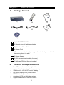
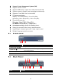
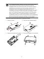
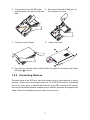
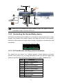
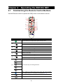
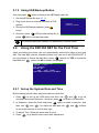
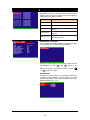
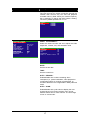
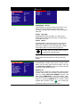
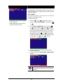
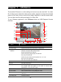
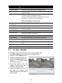
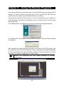
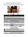
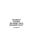
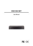
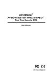
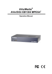
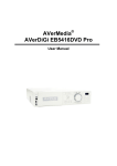
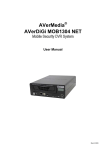
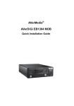
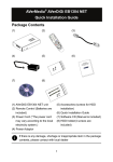
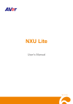
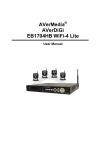
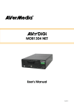
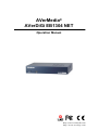
AVerMedia® AVerDiGi EB1304 NET Operation Manual http://www.avermedia.com http://www.averdigi.com FCC NOTICE (Class B) This device complies with Part 15 of the FCC Rules. Operation is subject to the following two conditions: (1) this device may not cause harmful interference, and (2) this device must accept any interference received, including interference that may cause undesired operation. Federal Communications Commission Statement NOTE- This equipment has been tested and found to comply with the limits for a Class B digital device, pursuant to Part 15 of the FCC Rules. These limits are designed to provide reasonable protection against harmful interference when the equipment is operated in a commercial environment. This equipment generates, uses and can radiate radio frequency energy and, if not installed and used in accordance with the instructions, may cause harmful interference to radio communications. Operation of this equipment in a residential area is likely to cause harmful interference in which case the user will be required to correct the interference at his own expense. CAUTION ON MODIFICATIONS To comply with the limits for the Class B digital device, pursuant to Part 15 of the FCC Rules, this device must be installed in computer equipment certified to comply with the Class B limits. All cables used to connect the computer and peripherals must be shielded and grounded. Operation with non-certified computers or non-shielded cables may result in interference to radio or television reception. Changes and modifications not expressly approved by the manufacturer could void the user’s authority to operate this equipment. European Community Compliance Statement (Class B) This product is conformity with the protection requirements of EU Council Directives 89/336/EEC amended by 92/31/EEC on the laws of the Member States relating to electromagnetic compatibility. Warning - This is a Class B product. In a domestic environment this product may cause radio interference in which case the user may be required to take adequate measures to correct this interference. DISCLAIMER No warranty or representation, either expressed or implied, is made with respect to the contents of this documentation, its quality, performance, merchantability, or fitness for a particular purpose. Information presented in this documentation has been carefully checked for reliability; however, no responsibility is assumed for inaccuracies. The information contained in this documentation is subject to change without notice. In no event will AVerMedia be liable for direct, indirect, special, incidental, or consequential damages arising out of the use or inability to use this product or documentation, even if advised of the possibility of such damages. TRADEMARKS AVerMedia is registered trademarks of AVerMedia TECHNOLOGIES, Inc. IBM PC is a registered trademark of International Business Machines Corporation. Macintosh is a registered trademark of Apple Computer, Inc. Microsoft is a registered trademark and Windows is a trademark of Microsoft Corporation. All other products or corporate names mentioned in this documentation are for identification and explanation purposes only, and may be trademarks or registered trademarks of their respective owners. COPYRIGHT © 2007 by AVerMedia TECHNOLOGIES, Inc. All rights reserved. No part of this publication may be reproduced, transmitted, transcribed, stored in a retrieval system, or translated into any language in any form by any means without the written permission of AVerMedia TECHNOLOGIES, Inc. The mark of Crossed-out wheeled bin indicates that this product must not be disposed of with your other household waste. Instead, you need to dispose of the waste equipment by handing it over to a designated collection point for the recycling of waste electrical and electronic equipment. For more information about where to drop off your waste equipment for recycling, please contact your household waste disposal service or the shop where you purchased the product. Battery Safety Information - - Store the batteries in a cool dry place. Do not dispose of used batteries in domestic waste. Dispose of batteries at special collection points or return to point of sale if applies. Remove the batteries during long periods of non-use. Always remove exhausted batteries from the remote control. Battery leakage and corrosion can damage this remote control, dispose of batteries safely. Do not mix old and new batteries. Do not mix different types of batteries: alkaline, standard (carbon-zinc) or rechargeable (nickel-cadmium). Do not dispose of batteries in a fire. The batteries may explode or leak. Never short circuit the battery terminals. - WARNING TO REDUCE RISK OF FIRE OR ELECTRIC SHOCK, DO NOT EXPOSE THIS APPLIANCE TO RAIN OR MOISTURE CAUTION IF THERE IS ANY DAMAGE, SHORTAGE OR INAPPROPRIATE ITEM IN THE PACKAGE, PLEASE CONTACT WITH YOUR LOCAL DEALER. WARRANTY VOID FOR ANY UNAUTHORIZED PRODUCT MODIFICATION NOTICE - INFORMATION IN THIS DOCUMENT IS SUBJECT TO CHANGE WITHOUT NOTIEC. - THE INFORMATION CONTAINED HEREIN IS TO BE CONSIDERED FOR REFERENCT ONLY. Table of Contents Chapter 1 Introduction .......................................................................1 1.1 Package Content........................................................................................ 1 1.2 Features and Specifications ....................................................................... 1 1.3 Front Panel ................................................................................................ 2 1.4 Back Panel................................................................................................. 2 1.5 Setting Up the DVR Unit ............................................................................ 3 1.5.1 Installing the Hard Disk.......................................................................... 3 1.5.2 Connecting Devices............................................................................... 5 1.5.3 Connecting the Sensor/Relay device..................................................... 6 1.5.3.1 I/O Card Sensor and Relay pinhole allocation: .................................. 6 Chapter 2 Operating the EB1304 NET...............................................8 2.1 Familiarizing the Remote Control Buttons.................................................. 8 2.1.1 Using AB Repeat Function..................................................................... 9 2.1.2 Using USB Backup Button................................................................... 10 2.2 Using the EB1304 NET for the First Time ................................................ 10 2.2.1 Set up the System Date and Time ....................................................... 10 2.3 Surveillance Screen ................................................................................. 11 2.4 Playback the Video .................................................................................. 11 Chapter 3 OSD Navigation Tree.......................................................14 3.1 Menu Function ......................................................................................... 15 Chapter 4 Using the USB Playback Console .................................25 4.1 Recommended system requirements....................................................... 25 4.2 Installing the USB Playback Console ....................................................... 25 4.3 Running the USB Playback Console........................................................ 26 4.3.1 To Cut and Save the Portion of the Recorded Video ........................... 28 4.3.2 Playback DVR Recorded File from Hard Disk ..................................... 28 4.3.3 Playback Backup File(*.dvr)................................................................. 29 Chapter 5 Backup Recorded Video File..........................................30 5.1 5.2 5.3 Recommended system requirements....................................................... 30 Familiarizing with HDD Backup Application.............................................. 30 To Backup Recorded Video File ............................................................... 31 Chapter 6 ImageVerification ............................................................32 6.1 To Run the ImageVerification ................................................................... 32 Chapter 7 i-Enhance .........................................................................33 7.1 To Use i-Stable ......................................................................................... 34 Chapter 8 Using the Remote Programs..........................................35 8.1 Familiarizing the Web Viewer Buttons...................................................... 36 8.1.1 To Setup Remote System Setting........................................................ 37 8.1.1.1 Camera Setup.................................................................................. 37 8.1.1.2 Record Setup ................................................................................... 38 8.1.1.3 Alarm/Sensor Setup ......................................................................... 39 8.1.1.4 Network Setup ................................................................................. 41 8.1.1.5 Password Change............................................................................ 43 8.2 Familiarizing the Remote Console Buttons .............................................. 44 8.2.1 To Setup Remote Console Setting....................................................... 45 8.3 Using the Remote Playback ..................................................................... 46 8.3.1 Familiarizing the Local Playback Buttons ............................................ 47 8.3.1.1 To Cut and Save the Wanted Portion of the Recorded Video........... 48 8.3.2 Familiarizing the Download and Playback Buttons .............................. 49 Appendix A Registering Domain Names .......................................................... 51 Chapter 1 1.1 Introduction Package Content FN 1 EB 2 4 3 5 7 DV R 6 8 9 0 ET 04 N ® B13 ia E y DVR Med e Securit Guide AVer Real-tim tallation Quick Ins ▼ ▼ A-B ▲ ▼ ▼ REC SEL L EF ▼ SP EED - EC T T FO CU S+ ME NU UP ▲ DO WN FO CUS - SP RIG HT ▼ ▼ ZO OM+ PT Z ZO OMEE D+ RM -H6 (1) (4) (2) (5) (3) (6) (7) (1) AVerDiGi EB1304 NET unit (2) Remote Control (batteries included) (3) Quick Installation Guide (4) Power Cord * The power cord varies depending on the standard power outlet of the country where it is sold. (5) Power Adapter (6) DVR accessories (including 4 screws) (7) Software CD (User Manual included) 1.2 Features and Specifications Non-PC stand-alone network digital video recorder 4 composite video inputs and 1 composite output VGA output for LCD or CRT monitor display On Screen Display(OSD) control menu MPEG4 video compression Auto-detect NTSC or PAL video system Support Web viewer on Internet Explorer 1 Support Central Management System(CMS) Support remote console Support USB backup to pen drive and external hard disk Support network, playback, and recording simultaneously Supports 1 hard disk drive (not included) Full-screen resolution: Display: 720 x 480 (NTSC) / 720 x 576 (PAL) Recording: 720 x 480 (NTSC) / 720 x 576 (PAL) Recording frame rate: D1 mode: 60fps(NTSC) / 50fps (PAL) CIF mode: 120 fps (NTSC) / 100fps (PAL) Scheduled recording (00:00~23:00 set by hour ) Search for recorded video files by date/time/event Input/Output: 4 sensor inputs and 1 relay output control Multiple language operation screens 1.3 Front Panel (1)(2) (3) (4) Name Function (1) DVR Power LED : Light when the unit is power on (2) HDD LED : Indicate the hard disk running state. Light when the HDD is running (Read/Write) (3) IR Sensor : Receive signal from the remote control to operate the unit (4) USB 2.0 Port : Connect to pen drive / external hard disk for backup 1.4 Back Panel (1) Name Function (1) : RJ-45 port (3) (5) (7) (2) (4) (6) (10) (8) (9) Ethernet connection port 2 (11) (12) Name Function (2) : Audio In Input the audio signal from audio output device which it has a power supply by itself. The audio is embedded with channel 1 i (3) Audio Out : The audio input device needs to be powered by external power. Output the audio signal to a audio out device which it has a power supply by itself i The audio output device needs to be powered by external power. (4) CH1 : Input the video camera signal and display it on channel 1 (5) CH2 : Input the video camera signal and display it on channel 2 (6) CH3 : Input the video camera signal and display it on channel 3 (7) CH4 : Input the video camera signal and display it on channel 4 (8) Video Out : Output the video signal to other vedio output device through BNC port The DVR unit support 2 video output ports and you can only select to output the video either from the VGA OUT or VIDEO OUT (9) : Output the video signal to a CRT or LCD monitor (10) Sensor In & Alarm Out : Support up to 4 sensor device and 1 relay device (Relay: 1A @ 125V AC/30V DC) (11) TV-VGA Switch : Switch to select the video output. Make sure to set the video output before turning on the unit (12) 12V DC : Connect the power adapter into this port 1.5 VGA OUT Setting Up the DVR Unit 1.5.1 Installing the Hard Disk The DVR unit allows user to install one hard disk. Before installing the hard disk, make sure to set the hard disk master jumper setting. Adjust the jumper setting according to the instructions on the hard disk label. i For hard disk spec, please referring to http://www.avermedia.com/nvd/hardware-recom_eb_c.asp 3 The “compatible hard disks” indicated in the above recommendation list only means that these commercially available hard disks were tested with AVerMedia products and functioned well under normal operation conditions. AVerMedia does not guarantee or provide warranties, explicitly, implied or statutory with respect to the reliability of the hard disk function or its compatibility. In no event AVerMedia shall be liable for damages, with respect to any business interruption of clients, lost profits, loss of programs or other data on your information handling system or otherwise. This includes direct, indirect, incidental, special, or consequential damages, resulting from the incompatibility caused by the usage of these hard disks, even if AVerMedia has expressly advised about the risk of such damages. The entire risk arising out of the use of any information attached here with is borne by the recipient. Follow the illustrated instructions below to install the hard disk: 1. Loosen all screws 2. Push the cover backward and lift 3. Loosen the hard disk rack 4 screws 4. Secure the brackets on the hard disk 4 5. Connect the end of the IDE cable 6. Secure the hard disk inside the unit and the power connector to the hard then replace unit cover disk 7. Push the cover forward 8. Secure the cover 9. You may now connect all the cables. When the power is connected, the Power turns on LED light 1.5.2 Connecting Devices The back panel of the DVR unit, user can connect up to 4 video cameras, 4 sensor devices, 1 alarm device and output video to a TV or CRT/LCD monitor. Connecting the unit to a pen drive or external hard disk through USB connection for backup, then use the bundled software enables user to transfer, playback and segment the video. Follow the illustration below to make the connection: 5 Each time you change the video display output, the power must be turned off and on to reset the DVR unit. 1.5.3 Connecting the Sensor/Relay device The Sensor and Alarm ports enable you to connect (4) sensor inputs and (1) relay outputs. Just connect the external sensor and relay pin directly to the pinhole. Check the table below and locate which pinhole is assigned to sensor input and relay output. 1.5.3.1 I/O Card Sensor and Relay pinhole allocation: The signal from the sensor (i.e., infrared sensors, smoke detectors, proximity sensors, door sensors, etc.) is being transmitted to the unit and this triggers the system to respond and send signal to relay device (i.e., alarm, telephone etc). Pin # Definition 1 Sensor 1 Ground signal 2 Sensor 1 signal 3 Sensor 2 Ground signal 4 Sensor 2 signal 5 Sensor 3 Ground signal 6 Sensor 3 signal 7 Sensor 4 Ground signal 8 Sensor 4 signal 9 Relay signal 6 10 Relay signal 7 Chapter 2 2.1 Operating the EB1304 NET Familiarizing the Remote Control Buttons Use the Remote control to operate the OSD menu on surveillance screen. (6) (1) FN (2) 1 EB DVR 2 4 (3) 3 5 7 8 9 (9) (10) A-B REC ▼ ▼ ▲ ▼ ▼ (18) (17) SELECT (8) (12) (13) (14) MENU (15) UP RIGHT ▼ ▲ ▼ LEFT (5) (7) 0 (11) (4) 6 FOCUS+ DOWN ZOOM+ (16) ▼ FOCUS- ZOOM- PTZ SPEED+ SPEED- RM-H6 Button Function (1) FN (2) 1 (3) 3 (4) 7 (5) 9 (6) 5 A functional key for multiple DVR system remote control Switch to Channel 1 As a number key for entering password Switch to Channel 2 As a number key for entering password Switch to Channel 3 As a number key for entering password Switch to Channel 4 As a number key for entering password Switch to CIF mode As a number key for entering password 2 4 (7) 6 As a number key for entering password 8 0 (8) A-B Set a playing recorded video from A point to B point segment and repeat playing on surveillance screen(See 2.1.1) Pause the playing (10) To play the video ▲ (9) 8 Function ( 11) Decrease the video playback at the speed of 2x, 4x 8x or 16x Fast play the video playback at the speed of 2x, 4x 8x or 16x ▼ ▼ (12) ▼ ▼ Button Stop playing / Stop recording (14) USB backup(see 2.1.2) ▼ (13) To move the selection to the left and right ▼ (15) ▲ To go up and down and select the items in the menu list or change the settings ▼ To enter the OSD Main menu / Exit from the main menu or sub-menu display (16) Make a selection (17) (18) i Enter sub-menu REC Start video recording The buttons which list below are not functional for the EB1304 NET. FOCUS+ FOCUS- ZOOM- ZOOM+ SPEED- SPEED+ PTZ 2.1.1 Using AB Repeat Function AB Repeat function allow user to set a video segment from A to B point and play on the surveillance screen until user stop. User also can backup AB Repeat file to pen drive or external hard disk (See 2.1.2). (play button) to call out the ▲ 1. Press SEARCH MODE menu to find the recorded video that user wants to playback. 2. Select TIME SEARCH or EVENT LIST. A-B A-B A-B A-B - TIME SEARCH (search by date and time): select the date and time from where you want to begin the video playback. - EVENT LIST (search by condition): select from the list. 3. During the playback, press press A-B A-B to set the A point of video segment. And then, again to set the B point of video segment. On the surveillance screen will display “A-B” and repeat playing the AB point video segment which user has set. To cancel AB repeat, press 9 A-B again. 2.1.2 Using USB Backup Button User can press button to backup the AB Repeat video file. 1. Set the AB Repeat file (see 2.1.1). 2. Plug in pen drive or external hard disk to DVR USB BAKCUP system. YES(SELECT) / NO(MENU) 3. During the AB Repeat playback, press button. 4. And then, press press (NO) to exit backup mode. i 2.2 (YES) to start backup file or The external hard disk needs to be powered by external power. Using the EB1304 NET for the First Time Upon connecting the power, the unit automatically detects the status of the hard disk. The hard disk must be formatted before user can use it with EB1304 NET. If you are prompt to format the hard disk, press (select) for YES to format the hard disk and (menu) for NO to remain unchanged. HARD DISKS INFORMATION VERSION 1 . 3. 03 HDD CHECKING . . . MASTER HDD SIZE 76GB 509MB HDD FORMAT YES (SELECT) / NO (MENU) 2.2.1 Set up the System Date and Time Before starting record video, adjust the date and time first. 1. Press to call up the OSD menu and then use and down and select Submenu. And then, press ▲ and to go up ▼ to confirm the selection. to move the selection to the left and right. 3. To adjust Time, follow the above step 2 and 3. 4. Press to go back to main menu after adjustment. 10 ▼ ▼ 2. In Submenu, select the Date and press again to make a selection. And then, use ▲ and ▼ o to adjust the date and use and buttons 2.3 Surveillance Screen To know if the channel is being recorded, the “ ” record symbol would appear beside the channel number. The (microphone) and (speaker) indicate that the audio is available. The information below the screen shows the current date and time, recording mode (record schedule setting), and the percentage of the used hard disk space. D1 (A) HDD 29% CIF(A) D1 mode Screen Preview HDD 29% CIF model Preview When you are in full screen preview, press the following buttons on the remote control to switch to different channel, or preview all 4 channels: 1 3 CH2: Camera 2 CH1: Camera1 2.4 7 CH3: Camera 3 9 CH4: Camera 4 5 QUAD: 4-Channel Playback the Video The DVR system can record and playback video simultaneously. Therefore, user don’t need to stop recording while playback the video. Press 2. Use the SEARCH METHOD TIME SEARCH EVENT LIST ▼ 1. ▲ and buttons to go up and ▼ Then, press or ▼ down and select TIME SEARCH or EVENT LIST. to make a selection. 11 TIME SEARCH (search by date and time): 1. Use the and ▲ buttons and select ▼ TIME SEARCH SEARCH TIME. Then press or ▼ HARD DISK again to make the selection. 2. : START TIME : 2006 / 05 / 04 END TIME : 2006 / 05 / 05 10 : 00 : 01 13 : 08 : 13 SEARCH TIME : 2006 / 05 / 04 10 : 00 : 01 In the SEARCH TIME, user may now select the date and time from where you want to begin the video playback. buttons to move the selection to the left and right. Use the buttons to select the date and time. Then press or ▼ ▼ and ▼ and ▼ Use the ▲ again to make 3. To start video playback, the time in second must be set. Use the selection to the right most. Use the or ▼ EVENT LIST (search by event): Use the ▲ and the list. Press buttons to select from ▼ or selection. User buttons and select the time in second. EVENT LIST again to make the ▼ 1. buttons to move the . ▼ Then press and ▲ ▼ the selection. and to go next S A A B A A B S A A 2006 / 05 / 03 2006 / 05 / 03 2006 / 05 / 03 2006 / 05 / 03 2006 / 05 / 03 2006 / 05 / 03 2006 / 05 / 03 2006 / 05 / 03 2006 / 05 / 03 2006 / 05 / 03 13 : 26 : 34 13 : 00 : 01 12 : 00 : 01 11 : 48 : 37 11 : 30 : 23 11 : 29 : 47 11 : 28 : 55 11 : 28 : 33 11 : 25 : 41 11 : 23 : 26 page or back to previous page. Listed below are the following recording conditions: A – Always Recording It records non-stop and automatically continue recording when interrupted S – Sensor Recording It records when the sensor has triggered M – Motion Recording It records when any movement has detected 12 13 : 26 : 50 13 : 16 : 46 13 : 00 : 01 12 : 00 : 00 11 : 31 : 18 11 : 30 : 13 11 : 28 : 58 11 : 28 : 55 11 : 28 : 32 11 : 23 : 30 B – Button Recording It records when the REC record button is pressed 2. The “” play symbol would appear beside the channel number when you are previewing in playback mode. 13 Chapter 3 OSD Navigation Tree The follow figure is an OSD menu tree map. To call out the OSD menu, press on the remote control. MAIN MENU CAMERA SELECT RECORD SELECT RECORD MODE VIDEO FORMAT RECORD FRAMERATE VIDEO QUALITY RECORD SCHEDULE SUBMENU HARD DRIVE SETUP SENSOR SETUP MOTION SETUP NETWORK SETUP USB BACKUP LANGUAGE SETUP 1 2 1 2 D1 D MPEG4 60 GOOD 3 3 4 4 RECORD SCHEDULE 00 : 00 - 01 : 00 ALWAYS REC ALWAYS REC 01 : 00 - 02 : 00 ALWAYS REC 02 : 00 - 03 : 00 03 : 00 - 04 : 00 ALWAYS REC 04 : 00 - 05 : 00 ALWAYS REC 05 : 00 - 06 : 00 ALWAYS REC 06 : 00 - 07 : 00 ALWAYS REC 07 : 00 - 08 : 00 ALWAYS REC 08 : 00 - 09 : 00 ALWAYS REC 09 : 00 - 10 : 00 ALWAYS REC 10 : 00 - 11 : 00 ALWAYS REC 11 : 00 - 12 : 00 ALWAYS REC 12 : 00 - 13 : 00 ALWAYS REC PASSWORD SETUP RECORD SCHEDULE 13 : 00 - 14 : 00 14 : 00 - 15 : 00 15 : 00 - 16 : 00 16 : 00 - 17 : 00 17 : 00 - 18 : 00 18 : 00 - 19 : 00 19 : 00 - 20 : 00 20 : 00 - 21 : 00 21 : 00 - 22 : 00 22 : 00 - 23 : 00 23 : 00 - 00 : 00 CURRENT NEW CONFIRM ALWAYS REC ALWAYS REC ALWAYS REC ALWAYS REC ALWAYS REC ALWAYS REC ALWAYS REC ALWAYS REC ALWAYS REC ALWAYS REC ALWAYS REC ENGLISH SUBMENU PASSWORD CHANGE VIDEO ADJUSTMENT DATE TIME AUTO RECORD AUTO SCAN PASSWORD SETUP AUDIO RECORD AUDIO MUTE VIDEO SYSTEM MULTIPLE REMOTE REMOTE ID NO ON OFF NTSC OFF 1 SENSOR SETUP SENSOR REC TIME ALARM OUT TIME CHANNEL - 1 CHANNEL - 2 CHANNEL - 3 CHANNEL - 4 010 010 NOT NOT NOT NOT MOTION SETUP MOTION CAMERA SENSITIVITIY MOTION RECORD TIME 1 2 HI 010 SEC ISB BACKUP TIME SET START : END : BACKUP CHANNEL BACKUP SIZE BACKUP EXECUTE CURRENT NEW CONFIRM 2006 / 04 / 20 17 : 54 : 50 ON HARD DRIVE SETUP OVERWRITE ENABLED NO HD1 SIZE 37 GB 78MB HD1 USED 16 GB 219MB HD1 FORMAT NETWORK SETUP IP MODE NW ENABLE VIDEO PORT UPGRADE PORT USER SET NW PASSWORD SET NW PASSWORD PASSWORD SETUP SUPERUSER USER(NETWORK) VIDEO ADJUSTMENT CAMERA BRIGHTNESS CONTRAST HUE SATURATION RESET TO DEFAULT VALUE 21% AUTO SCAN AUTO CHANNEL-1 CHANNEL-2 CHANNEL-3 CHANNEL-4 SEC SEC INSTALLED INSTALLED INSTALLED INSTALLED STATIC 1 2 5001 5005 1 3 4 3 4 2006/09/23 17:00:02 2006/09/26 18:00:00 1 2 3 4 73G 89MB 14 1 050 050 000 024 OFF 10 SEC 10 SEC 10 SEC 10 SEC 3.1 Menu Function If the unit is currently recording the video, user may have to stop video recording to change the settings. Use remote control to navigate in the OSD menu. The red frame turns yellow when you are making a selection. OSD MENU MAIN MENU CAMERA SELECT RECORD SELECT RECORD MODE VIDEO FORMAT RECORD FRAMERATE VIDEO QUALITY RECORD SCHEDULE SUBMENU HARD DRIVE SETUP SENSOR SETUP MOTION SETUP NETWORK SETUP USB BACKUP LANGUAGE SETUP Description 1 2 1 2 D1 MPEG4 60 GOOD 3 3 4 4 CAMERA SELECT : Enable/disable the channel number to display the video on the surveillance screen RECORD SELECT : Enable/disable the channel number to record video The channels which could be recorded should be enabled in the CAMERA SELECT first. i ENGLISH RECORD MODE : Select D1/CIF recording mode Under D1 mode, the video recording is in full screen resolution and takes turns from one channel to the next one when Auto Scan enables. Each channel is recorded only at a maximum frame rate of 15fps. User can switch to view the video in single full screen or QUAD screen Whereas in CIF mode, video recording is at a lower resolution, but each video is recorded in 30fps/25fps (NTSC/PAL). User can switch to view the video in single full screen or QUAD screen VIDEO FORMAT : The recorded video is in MPEG4 format RECORD FRAME RATE : Set the number of frames per second to be recorded. Refer to the table below for the available record frame rate settings. The higher the frame rate is, it uses more hard disk space Video Standard NTSC PAL D1 60, 20, 4 48, 20, 4 CIF 120, 60, 40, 20, 4 100, 48, 20, 4 Record Mode VIDEO QUALITY : Select the video quality setting from BEST, HIGH, MEDIUM, GOOD, NORMAL or LOW. BEST – best record quality but less record hours LOW – longest record hour but quality is ordinary NORMAL – allows you to record more hours but the quality of the recorded video is moderate. LANGUAGE SETUP : Select from the available languages 15 OSD MENU Description RECORD SCHEDULE 00 : 00 - 01 : 00 ALWAYS REC 01 : 00 - 02 : 00 ALWAYS REC 02 : 00 - 03 : 00 ALWAYS REC 03 : 00 - 04 : 00 ALWAYS REC 04 : 00 - 05 : 00 ALWAYS REC 05 : 00 - 06 : 00 ALWAYS REC 06 : 00 - 07 : 00 ALWAYS REC 07 : 00 - 08 : 00 ALWAYS REC 08 : 00 - 09 : 00 ALWAYS REC 09 : 00 - 10 : 00 ALWAYS REC 10 : 00 - 11 : 00 ALWAYS REC 11 : 00 - 12 : 00 ALWAYS REC 12 : 00 - 13 : 00 ALWAYS REC RECORD SCHEDULE: By default, in 24 hours, the recording schedule is set to always record every hour. Refer to the table below to customize the recoding condition Condition Description NO REC Disable video recording ALWAYS REC Record non-stop MOTION REC Start recording when any movement is detected SENSOR REC Start recording triggered BUTTON 2006 / 04 / 20 17 : 54 : 50 ON ON NO ON OFF NTSC OFF 1 Start recording the sensor has when the record button is pressed PASSWORD CHANGE : Set a security combination number. There are two type of user password – SUPERUSER and USER. PASSWORD CHANG SUPERUSER USER(NETWORK) Use the number button on the remote control to enter the password. Or use ▲ and ▼ button to the select the security combination number. Press or ▼ SUBMENU PASSWORD CHANGE VIDEO ADJUSTMENT DATE TIME AUTO RECORD AUTO SCAN PASSWORD SETUP AUDIO RECORD AUDIO MUTE VIDEO SYSTEM MUTIPLE REMOTE REMOTE ID REC when button to confirm. SUPERUSER: Superuser has the authority of formatting hard disk, changing system settings, remote monitor the DVR system and changes the system settings. The factory default password is 111111. PASSWORD SETUP CURRENT NEW CONFIRM 16 OSD MENU Description USER(NETWORK): The login account for remote connection through the internet. User account only can view and playback recorded video by Web viewer (ex: Internet Explorer), but no authority to change the DVR system’s setting. The factory default password is 111111. SET NW PASSWORD CURRENT NEW CONFIRM SUBMENU PASSWORD CHANGE VIDEO ADJUSTMENT DATE TIME AUTO RECORD AUTO SCAN PASSWORD SETUP AUDIO RECORD AUDIO MUTE VIDEO SYSTEM MUTIPLE REMOTE REMOTE ID VIDEO ADJUSTMENT : 2006 / 04 / 20 17 : 54 : 50 ON ON NO ON OFF NTSC OFF 1 Select the camera number and set to adjust the video brightness, contrast, hue, and saturation value VIDEO ADJUSTMENT CAMERA BRIGHTNESS CONTRAST HUE SATURATION RESET TO DEFAULT VALUE 1 050 050 000 024 NO DATE : Set the current date TIME : Set the current time AUTO RECORD : Enable/disable auto continue recording when interrupted (i.e., power breakdown, video playback or configuration setup). It continue recording after 10 second of idleness. This is applicable in Always Record mode AUTO SCAN : Enable/disable auto cycle switch to display the next channel when in full screen preview. User can set different switch time for each channel. The time range is from 5 ~30 seconds. 17 OSD MENU SUBMENU PASSWORD CHANGE VIDEO ADJUSTMENT DATE TIME AUTO RECORD AUTO SCAN PASSWORD SETUP AUDIO RECORD AUDIO MUTE VIDEO SYSTEM MUTIPLE REMOTE REMOTE ID Description 2006 / 04 / 20 17 : 54 : 50 ON ON NO ON OFF NTSC OFF 1 AUTO SCAN AUTO SCAN CHANNEL - 1 CHANNEL - 2 CHANNEL - 3 CHANNEL - 4 OFF 10 SEC 10 SEC 10 SEC 10 SEC PASSWORD SETUP : Enable/disable full system password protection. This would prevent unauthorized user to stop video recording, change system settings and formatting the hard disk AUDIO RECORD : Enable/disable audio recording. To record sound, make sure the audio input device(ex: microphone) is connected to the unit AUDIO MUTE : Enable/disable to hear audio sound. To hear sound, make sure the unit is connected to an audio output device (ex: speaker). If user recorded video in audio mute status, there is no sound when playback i The audio input and output device need to be powered by external power. VIDEO SYSTEM: DVR system will auto detect the video system and display SUBMENU PASSWORD CHANGE VIDEO ADJUSTMENT DATE TIME AUTO RECORD AUTO SCAN PASSWORD SETUP AUDIO RECORD AUDIO MUTE VIDEO SYSTEM MUTIPLE REMOTE REMOTE ID 2006 / 04 / 20 17 : 54 : 50 ON ON NO ON OFF NTSC OFF 1 MUTLIPLE REMOTE: Enable/disable multiple DVR system remote control. When user has more than one DVR system, user can use MULTIPLE REMOTE function to control all DVR system by single remote control. REMOTE ID: Assign the ID number for multiple DVR system remote controls. When there are more than one DVR systems, user can enable MULTIPLE REMOTE function, and then assign REMOTE ID to each DVR system. Then, user can just use one remote control to control all DVR system by pressing REMOTE ID. To remote control multiple DVR systems, press FN and number key (remote ID number) on the remote control. 18 OSD MENU HARD DRIVE SETUP OVERWRITE ENABLED YES HDD SIZE 37 GB 78MB HDD USED 0 GB 232MB HDD FORMAT Description OVERWRITE ENABLED : 0% Enable/disable overwriting the earliest record when the hard disk space runs out. By default, the HDD overwrite setting is enabled HDD FORMAT : For security purpose, you may have to enter the password to format hard disk To format hard disk: 1. Use the ▲ and ▼ buttons to go up and or ▼ down and select HDD FORMAT. Then press 2. In the CHECK PASSWORD screen, press . Then use the ▲ and ▼ buttons or to select the security combination number. Repeat till you key in the last number. Also, user can use the number button on the remote control to enter or button again the password. Press to make the selection. To move the selection to the left and right, use ▲ and ▼ buttons ▼ ▼ * HDD SIZE shows the total capacity of the hard disk. * HDD USED shows the amount of space that has been used. CHECK PASSWORD ENTER PASSWORD 3. After entering the last number, the system will format the hard disk 4. It is done when the “HDD FORMAT COMPLETED” appears HARD DRIVE SETUP OVERWRITE ENABLED YES HDD SIZE 37 GB HDD USED 0 GB HDD FORMAT 78MB 0MB 0% HDD FORMAT COMPLETED Formatting the hard disk will permanently delete all the records and can no longer be retrieved 19 OSD MENU SENSOR SETUP SENSOR REC TIME ALARM OUT TIME CHANNEL - 1 CHANNEL - 2 CHANNEL - 3 CHANNEL - 4 Description 010 010 NOT NOT NOT NOT SENSOR REC TIME : SEC SEC INSTALLED INSTALLED INSTALLED INSTALLED Set the amount of time (in second) to start record when the sensor has triggered ALARM OUT TIME : Set the amount of time (in second) to continue sending the alarm once triggered CHANNEL 1~4 : Customize the initial state of the attached sensor. Refer to the table below to customize the sensor state 3 4 Indicates that there is no sensor connected NORMAL OPEN Indicates that the initial state of the sensor is normal open. Video recording initiates when there is a changes in the sensor state NORMAL CLOSE Indicates that the initial state of the sensor is normal close. Video recording initiates when there is a changes in the sensor state MOTION CAMERA : Enable/disable the channel number to detect motion. SENSITIVITY : Set the sensitivity level. The sensitivity is from H (High), 9~ 2 and L (Low). MOTION RECORD TIME : Set the amount of time (in second) to record when motion is detected. NETWORK SETUP: Setup the network parameters for the internet or intranet remote monitor or playback. IP MODE: The system provides 3 types of IP setup mode – Static, DHCP, and PPPOE. Use and ▲ ▼ buttons to go up and down and select IP MODE, and then press ▼ ▲ and buttons to change the selections and press or . Use to make a selection. STATIC: Assigns a constant IP address for the DVR system. Use ▲ and ▼ buttons to go up and down and select items, and then press 20 ▼ to make selection. Use and or to move left and right to select or enter the configuration value. - IP ADDRESS: Assign a constant IP address which a real IP addresses give from ISP to DVR system. - SUBNET: It is a bitmask used to identify the sub network and how many bits provide room for ▼ STATIC 1 2 80 5005 4 NOT INSTALLED ▼ NETWORK SETUP IP MODE NW ENABLE VIDEO PORT UPGARDE PORT 3 Description ▼ MOTION SETUP 1 2 MOTION CAMERA SENSITIVITIY L MOTION RECORD TIME 010 SEC Condition OSD MENU STATIC 1 2 80 5005 3 4 - - - host addresses. Enter the subnet mask of the IP address which user has assigned to DVR system. GATEWAY: A network device act as a passageway to internet. Enter the network gateway IP address DNS: Domain Name Server translates domain names (such as www.abb.com.tw) to IP addresses. Enter the IP address of DNS if it is available. MAC ADDRESS: Only for user information. Don’t need to enter the MAC address. When all parameters are set, select the CHANGE to confirm the configuration. NETWORK INFORMATION IP ADDRESS SUB NET GATEWAY DNS MAC ADDRESS CHANGE 192.168.153.100 255.255.255.255 192.168.153.254 192.168.153.1 00.00.00.00.00.00 DHCP: Assign the IP address by local DHCP ▲ ▼ and server to DVR system. Use buttons to go up and down and select DHCP, and then press or to make selection. ▼ NETWORK SETUP IP MODE NW ENABLE VIDEO PORT UPGARDE PORT Description i The DHCP (Dynamic Host Configuration Protocol) is a set of rules used by a communications device (such as a computer, router or networking adaptor) to allow the device to request and get an Internet address from a server which has a list of addresses available for assignment The DVR system will try to get an IP address from the DHCP server. A message window will show up as below: GET IP NOW! WAITING... 21 STATIC 1 2 80 5005 3 When DVR system gets an IP address from DHCP server, the information will display as below: 4 NETWORK INFORMATION IP ADDRESS SUB NET GATEWAY DNS MAC ADDRESS 192.168.153.100 255.255.255.255 192.168.153.254 192.168.153.1 00.00.00.00.00.00 PPPOE: Point-to-Point Protocol over Ethernet is a network protocol for encapsulating PPP frames in Ethernet frames. It is used mainly with ADSL services. If your network is using ADSL service connecting to internet, and then, select PPPOE mode. Use ▲ and ▼ buttons to go up and down and select PPPOE, and then press or to make selection. A message window will show up as below: ▼ NETWORK SETUP IP MODE NW ENABLE VIDEO PORT UPGARDE PORT Description GET IP NOW! WAITING... When DVR system get an IP address, the information will display as below: NETWORK INFORMATION IP ADDRESS SUB NET GATEWAY DNS MAC ADDRESS CHANGE 000.000.000.000 000.000.000.000 192.168.153.254 192.095.000.001 00.00.00.00.00.00 NW ENABLE: Allow internet remote user to playback or monitor the channels. Without enabling the network function, the channels cannot be playback or monitor from remote site. F 1 is Channel 1 F 3 is Channel 3 i F 2 is Channel 2 F 4 is Channel 4 ▼ Use ▲ and ▼ buttons to go up and down and select NW ENABLE (network enable), and then or and to move to the selection. press Use ▲ 22 and ▼ OSD MENU ▼ buttons to change the selections NETWORK SETUP IP MODE NW ENABLE VIDEO PORT UPGARDE PORT Description STATIC 1 2 80 5005 values and press 3 4 or ▼ OSD MENU to confirm. VIDEO PORT: A port for the remote connection. Any port can be assigned as a video port, except the ports already used by the network services. The default video port is 80. Use and ▲ ▼ buttons to go up and down and and and ▼ buttons to change the selections values and press ▼ to move to the selection. Use or ▼ select VIDEO PORT, and then press ▼ or ▲ to confirm. UPGRADE PORT: A port for the remote update DVR system firmware. Any port can be assigned as an upgrade port, except the ports are already used by the network services. The default upgrade port is 5005. For Upgrading DVR firmware, please contact your local dealer. Please DO NOT cut off the power of the DVR system while the firmware is upgrading. Power failure will cause the permanent damage of the DVR system. i Use ▲ and ▼ buttons to go up and down and ▼ or BACKUP CHANNEL BACKUP SIZE BACKUP EXECUTE 3 89MB 1 73GB 2 4 Use ▲ and ▼ buttons to go up and down and select USB BACKUP, and then press ▼ Use and ▲ press 1. 2. 3. and . to move left and right. And, use buttons to change the value and ▼ or or ▼ 10 : 00 : 01 13 : 08 : 13 USB BACKUP: Using USB device (ex. Pen drive or External Hard disk) to backup partial recorded video and playback on PC. ▼ START TIME : 2006 / 05 / 04 END TIME : 2006 / 05 / 05 ▲ to confirm. ▼ USB BAKCUP TIME SET ▼ and ▼ buttons to change the selections values and press and to move to the selection. Use or ▼ select UPGRADE PORT, and then press to confirm. Select the START TIME and END TIME. Select the channels which user wants to backup. The DVR system will display the system hard disk space and backup file size. 23 OSD MENU Description USB BAKCUP TIME SET 4. START TIME : 2006 / 05 / 04 END TIME : 2006 / 05 / 05 10 : 00 : 01 13 : 08 : 13 BACKUP CHANNEL BACKUP SIZE BACKUP EXECUTE 3 89MB 1 73GB 2 And then, select BACKUP EXECUTE to start backup video to the USB device. 4 80% USER REMAINDER 0GB 5. 820MB When backup is done, press any key to back to main menu. USB BACKUP SUCCESS PRESS ANY KEY TO EXIT 6. To view the backup file, using USB Playback Application(see 4.3) - Remember to plug in the USB device before starting to backup. - The DVR system doesn’t supply the power to external hard disk. Therefore, the external hard disk must be power supplied by self. i 24 Chapter 4 4.1 Using the USB Playback Console Recommended system requirements Pentium®4 2.4GHZ or above Windows®2000/ XP DDR 256 MB Graphic function must support DirectDraw Audio card or built-in Speaker 1 available USB2.0 port 4.2 Installing the USB Playback Console To install the USB Playback Console: 1. Place Installation CD into the CD-ROM drive. When the installation main screen appears, click Install USB Playback Console and then follow the on screen instructions 2. Select the language you prefer 3. 4. Click OK to install the application Click Exit to close the installation main screen. You may plug in the pen drive or external hard disk now. 25 4.3 Running the USB Playback Console To run the application, click the icon on the PC desktop (1) (2) (3) (4) (5) (6) (7) (8) (9) (10) (11) (17) (12) (13) (16) Name (1) (14) (15) Function Video playback screen To select the video file for playing. The playback application supports *.dvr and *.avf file. (2) Open File - DVR Recorded File (HD): To playback the recorded video from the hard disk which was recording video on the DVR system. (Also see 4.3.2) - Backup File(.dvr): The file is backup and save in *.dvr file format. (Also see 4.3.3) - Backup File(.avf): The file is backup and save in *.avf file format. The recorded video backup to pen drive is in *.avf. 26 Name Function Select the event you want to playback. The event list only available when user select to playback in DVR Recorded File(HD). (3) Event List (4) Full screen Use the entire area of the screen to only display the video. To return, press the right button of the mouse or ESC on the keyboard. When you switch to full screen in multiple-screen mode, Left click to toggle to only display one of the video in the multiple-screen mode or all. (5) Segment Keep a portion of the recorded video (see also 4.3.1) (6) Output Save the segmented file in *.mpg or *.avi format (see also 4.3.1). (7) Snapshot Capture and save the image either in *.jpg or *.bmp format (8) Print Print the image (9) HDD Backup To call out HDD Backup application. (See Chapter 5) (10) Video Enhancer To call out i-Enhance application. ( See Chapter 7) (11) Watermark To call out ImageVerification application. (See Chapter 6) (12) Status bar Display the recorded date, time and play speed. (13) Progress bar Show the progress of the file being played. You may move the bar to seek at any location of the track. (14) Playback Controller (15) Split Screen Mode Begin: Move at the beginning of the recorded video file. Previous: Go back to the previous frame by frame. Slower: Play the recorded video file at the speed of 1/2X, 1/4X, or 1/8X. Rewind: Wind back the recorded video file. Pause: Briefly stop playing the recorded video file. Play: Play the recorded video file. Faster: Play the recorded video file at the speed of 2x, 4x, or 8x. Next: Go to the next frame by frame. End: Go to the end of the recorded video file. Select from different screen view to playback the recorded video file of the entire camera or one camera on screen. Exit/ Minimize the application or chose Cancel to go back to the application (16) Exit 27 Name (17) Sound /Sound bar Function Turn on and off the sound Increase and decrease the volume 4.3.1 To Cut and Save the Portion of the Recorded Video 1. Use the Playback Control buttons or drag the bar on the playback progress bar and pause on where you want to start the cut. Then, click Segment to set the begin mark. 2. Use the Playback Control buttons or drag the bar on the playback progress bar and pause on where you want to end the cut. Then, click Segment to set the end mark. To cancel segmentation, click Segment button again. 3. 4. Click Output button to save the wanted portion. In the Save As dialog box, locate on where user wants to save the file, type the filename, and select the video format. 4.3.2 Playback DVR Recorded File from Hard Disk 1. Please have the hard disk which containing of recorded video data install on your PC or using external USB enclosure to connect to your PC. 2. Click Open File button 3. Select DVR Recorded File(HD) and click OK. 4. Select the hard disk drive from Select Disk window and click OK. 5. And then, the Event List window appears. Select the event that user wants to play and click OK. 28 4.3.3 Playback Backup File(*.dvr) 1. Click Open File button. 2. Select Backup File(*.dvr) and click OK. 3. Locate the backup file folder and click OK. i 4. When open the backup video file, just locate the where backup file folder is. And then, Playback Date/Time Selection window appears. Select the date and time and click OK. 29 Chapter 5 5.1 Backup Recorded Video File Recommended system requirements Pentium®4 2.4GHZ or above Windows®2000/ XP DDR 256 MB Graphic function must support DirectDraw Audio card or built-in Speaker 1 available USB2.0 port 5.2 Familiarizing with HDD Backup Application (2) (1) (3) (4) (5) (6) (7) (8) (10) Name (1) All recorded video events list (9) Function No.: the list order number Record: the record type(see also Chapter 2.3.1) Begin Time: the beginning of record time End Time: the end of record time Display first frame of each recorded channel video which user had selected. (2) (3) Progress bar Show the progress of the event being played. User may move the bar to seek at any location of the track (4) Source Disk To select the hard disk drive 30 Name Function (5) Target Path To locate on where user want to save the file (6) Event (%) Display the backup progress rate of event in percentage (7) Total (%) Display the total backup progress rate in percentage (8) Stop Stop backup progress (9) Start Start backup progress (10) Select All 5.3 1. 2. 3. 4. Select all listed recorded video events. Click the check box again to cancel for selecting all events. To Backup Recorded Video File Please have the hard disk which was recording video on the DVR system install on your PC or using external USB enclosure to connect to your PC. To run the HDD Backup application, click the HDD Backup button on USB Playback Application main interface. Click Browse in Source Disk to locate the recorded video file. And then, the Select Disk windows will appear as below: 5. Select the hard disk drive from Select Disk windows. All available hard disk will list on the Select Disk windows with size and name 6. Select the hard disk drive and click OK 7. And then, all the recorded video files will list out. 8. Select the event which user wants to backup. Or mark the Select All to select all listed recorded video event 9. Locate on where user wants to save the backup file 10. Click Start to process backup 11. To stop the backup progress, click Stop 12. To play the backup file, see 4.3.3. 31 Chapter 6 ImageVerification Image Verification is a watermark-checking program to identify the authenticity of a saved image (e.g. by snapshot). This program can only verify uncompressed bmp image files. 6.1 1. 2. 3. 4. To Run the ImageVerification To run the ImageVerification application, click the Watermark button on USB Playback Application main interface. In the ImageVerification screen, click Load Source Image and locate the image source. Click Verify Image to begin the process. Check the result in the Processed Image screen. If the picture is unmodified, the image in the Source Image and Processed Image screen would be exactly the same. If the picture is being modified, a warning dialog box would prompt and the modified area is highlighted. 32 Chapter 7 i-Enhance The bundled i-Enhance is a video editing tool and can only be used with *.dvr video file. It allows you to adjust the video picture quality, segment and save the selected portion of the video, zoom in and out the image, and print or save the screen shot. You can also save the setting and apply it on other files. To run i-Enhance application, click i-Enhance button on USB Playback Console interface. (16) (15) (17) (18) (14) (19) (13) (12) (20) (21) (11) (22) (23) (24) (25) (10) (9) (1) Name (2) (3) (4) (5) (6) (7) (8) Function (1) Open File Access *.dvr video file. (2) Save Image Capture and save the screen shot in *.bmp format. (3) Playback Control Buttons Begin: Move at the beginning of the video file. Previous: Go back to the previous frame. Rewind: Wind back the video file. Pause: Temporary stop playing the video file. Play: Play the video file. Faster: Play the video file at the speed of 2x, 4x, or 8x. Next: Go to the next frame. End: Go to the end of the video file. (4) Save Video Save the edited or segmented video in *.avi format. (5) Print Print the screen shot. (6) Segment Mark the beginning and the end of the selected portion of the video. Two triangle marks will appear on the slider. To cancel video segmentation, click this button again. (7) Zoom Buttons Enlarge, reduce, and set the image back to normal size. (8) Full Screen Use the entire screen to only display the video. (9) Default Set the video back to original state and delete all the changes in the history box. (10) History Box List all the actions. 33 Name Function (11) Undo Delete the last action. (12) Noise Reduce Adjust the softness and repair the damaged colours. (13) Sharpness Improve the overall image by enhancing edges. This gives the image more depth. (14) Effects Gray Scale: convert the image into black and white (monochrome). Normalize: adjust the brightness intensity. Equalize: automatically adjust the images that are too dark. De-interlace: smooth out the overlying frames. Static: de-interlace for motionless scene. Dynamic: de-interlace for moving scene. (15) Picture Adjustment Adjust the Brightness, Contrast, Saturation, Hue and Gamma. (16) Original Screen Display the original state of the image. (17) Temporary Setting Block Display the sample settings. Click the sample to apply the setting on the current video. (18) Status Bar Display the date, and time of the video. (19) Progress Bar Show the progress of the file being played. You may move the bar to seek at any location of the track. (20) i-Stable To reduce the jolt in the recorded video.(also see Chapter 7.1) (21) Add Setting Include the new setting to the temporary setting block. (22) Rename Change the name of the selected setting in the temporary setting block. (23) Delete Permanently remove the selected setting in the temporary setting block. (24) Load Setting Call the saved settings. (25) Save Setting Store the settings in the temporary setting block. 7.1 To Use i-Stable The i-Stable function can reduce the jolt in the recorded video. 1. Click Open File button and select the recorded video. 2. And then, click i-Stable button. 3. i-Stable windows will show up. 4. Select the smoothness level – 1(Low), 2, 3, 4, and 5(High). The default value is 3. 5. Click Play button, and then i-Stable function will start to initial the recorded video. 6. When the initialize is done, user will see the original and stabilized recorded video play in two windows. 34 Chapter 8 Using the Remote Programs User can use Microsoft Internet Explorer to access DVR system by entering the IP address. To use this feature, make sure that you PC and EB 1304 NET both are connected to the internet and the Network feature is enabled. Accessing this feature for the first time you will be prompted by your browser to install WebCamX.cab, allow the installation and you should be able to connect and login afterwards. For Windows 2000, click Yes when the Security Warning dialog box appears. For Windows XP, click Install when the Internet Explorer - Security Warning dialog box appears. After installing the WebCamX.cab and when connecting to the DVR system, you are required to enter User ID (Superuser or User) and password (default password is 111111) and select the type of network. Superuser has the authority to remote setup the DVR system configuration on Web Viewer. i Changing the Superuser and User default password is strongly recommended. 35 8.1 Familiarizing the Web Viewer Buttons Right-clicking on the Web Viewer video screen, enables you to start video recording, change video quality, switch camera and enable/disable DirectDraw. Name Function (1) DirectDraw i Enhance the video quality. Not all graphic cards can support this function. If you can not see the screen display correctly or screen is messed, please check with VGA card vendor. (2) Received file size Indicate the size of the data being sent per second. (3) Camera frames Indicate the number of frames per second. (4) One screen view To view single camera view on screen. User can right click on the screen to switch to different camera view. (5) Split screen view To view 4 camera on screen simultaneously. (6) Record Start to record the video of the selected camera in AVI format. Directly click screen to select the channel that user wants to record and press Record button. (7) Remote Console Initiate Remote Console. It allows you to control DVR server (see also Chapter 8.2). (8) Remote setup Change the DVR server settings (see also Chapter 8.1.1). i Only Superuser has the authority to remote setup DVR system. (9) Snapshot Capture and save the screen shot in *.bmp format. (10) Full screen Use the entire area of the screen to only display the video. To return, Right click the mouse or press ESC on the keyboard. 36 Name Function (11) Select cameras to view Select to the view camera from different server. In Select Camera dialog box, Display column, click to enable/disable viewing the camera. Click Add Server and select the server type between DVR and IP Cam to add. Click Delete Server to delete the selected item. Click Import to load the previous saved list. Click Export to save the list. Click Apply All to change all the camera video quality based on the selected setting. Click OK to exit. 8.1.1 To Setup Remote System Setting Click OK to exit and save the setting and Cancel to exit without saving the setting. The setting here applies to Remote DVR only. i After changed the DVR system setting, refresh your web browser in order to apply the new setting to the DVR system. 8.1.1.1 Camera Setup (1) (2) (3) (4) (1) Camera Select: Enable/disable the channel number to display the video on the surveillance screen (2) Auto Scan Enable/disable auto cycle switch to display the next channel when in full screen preview. 37 (3) Video Adjustment Select the camera and adjust the Brightness, Contrast, Hue and Saturation of the selected camera. (4) Default Value Set the video value back to default 8.1.1.2 Record Setup (1) (2) (3) (4) (5) (6) (7) (8) (1) Record Select Enable/disable the channel number to record video i The channels which could be recorded should be enabled in the CAMERA SELECT first. (2) Record Mode Select D1/CIF recording mode. Under D1 mode, the video recording is in full screen resolution. Each channel is recorded at a maximum frame rate of 15fps. You can switch to view the video in single full screen or 4 split screen. Whereas in CIF mode, video recording is at a lower resolution, but each video is recorded in 30fps/25fps (NTSC/PAL). (3) Record Frame Rate Set the number of frames per second to be recorded. Refer to the table below for the available record frame rate settings. The higher the frame rate is, it uses more hard disk space Video Standard NTSC PAL Record Mode D1 60, 20, 4 48, 20, 4 CIF 120, 60, 40, 20, 4 100, 48, 20, 4 38 (4) Video Quality Select the video quality setting from BEST, HIGH, MEDIUM, GOOD, NORMAL or LOW. (5) Auto Record Enable/disable auto continue recording when interrupted (i.e., power breakdown, video playback or configuration setup). It continue recording after 10 second of idleness. This is applicable in Always Record mode under schedule setting. (6) Audio Record Enable/disable audio recording. To record sound, make sure the microphone is connected to the unit (7) Disk Overwrite Enable Enable/disable replacing the earliest record when the hard disk space runs out. By default, the HDD overwrite setting is enabled (8) Motion Detection - Motion Camera Enable/disable the channel number to detect motion. - Motion Record Time Set the amount of time (in second) to record when a motion has detected. - Sensitivity Set the sensitivity level. The sensitivity is from high, 9~ 2 and low. 8.1.1.3 Alarm/Sensor Setup (3) (1) (2) (1) Alarm Setup - Mail Alarm Enable Enable/disable alarm sending mail when alarm has triggered or motion has detected. 39 i The Motion Detection must be enabled first, the alarm sending mail will send out the mail when detect motion. - Alarm Out Time Set the amount of time (in second) to continue sending the alarm once activated (2) Sensor Setup - Sensor Status Customize the initial state of the attached sensor for every camera. Refer to the table below to customize the sensor state. Not installed: Indicates that there is no sensor connected Normal open: Indicates that the initial state of the sensor is normal open. Video recording initiate when there is a changes in the sensor state Normal close: Indicates that the initial state of the sensor is normal close. Video recording initiate when there is a changes in the sensor state - Sensor Record Time Set the amount of time (in second) to record after the sensor has been triggered (3) E-Mail Setup - SMTP Enter the SMTP server - User ID & Password Enter User ID and Password for e-mail server user identification - From Enter the sender e-mail address - To The recipient e-mail address and separate it with a semicolon - Subject Enter the message title - Message Type the message 40 8.1.1.4 Network Setup (1) (2) (3) (1) IP Mode - Static IP Assign a fixed and global IP address for the DVR system IP: Assign a constant IP address which real IP addresses give from ISP. Mask: Enter the subnet mask of the IP address which user has assigned to DVR system. i It is a bitmask used to tell how many bits in an octet(s) identify the subnetwork, and how many bits provide room for host addresses. Gateway: Enter the network gateway IP address DNS: Domain Name Server translates domain names (such as www.abb.com.tw) to IP addresses. It will translate the domain name into IP address when DVR system request. - DHCP Assign the IP address by local DHCP server to DVR system. i The Dynamic Host Configuration Protocol (DHCP) is a set of rules used by a communications device (such as a computer, router or networking adaptor) to allow the device to request and get an Internet address from a server which has a list of addresses available for assignment. - PPPOE Point-to-Point Protocol over Ethernet is a network protocol for encapsulating PPP frames in Ethernet frames. It is used mainly with ADSL services. (2) Server Port A port is using for the remote connection. Any port can be assigned as a server port, except the ports already used by the network services. (3) DDNS DDNS (Dynamic Domain Name Service) is a data query service mainly used on the Internet for translating domain names into Internet addresses. Users can register their own domain name on http://www.ddns.avers.com.tw. (See 41 Appendix A) - Domain Name Enter the domain name that user wanted. - Auth Key A password use to access DDNS to register the domain name. MAC address of the DVR system is the key for user to register the domain name on AVerMedia DDNS web site. To find MAC address of your DVR system, follow the steps below: 1. In OSD menu, select NETWORK SETUP 2. Select any one of IP mode 3. A NETWORK INFORMATION windows will show up 4. MAC address of DVR system is display as shown 42 8.1.1.5 Password Change Click Remote setup button on Web Viewer main interface, and then, click User button to call out the Password Change interface. (1) (2) (1) Superuser Change the remote accessing password of super user. Superuser has the authority to remote setup the DVR system configuration on Web Viewer. - Password Enter the new password - Password Confirm Re-enter password to confirm (2) User Change the remote accessing password of user - Password Enter the new password - Password Confirm Re-enter password to confirm 43 8.2 Familiarizing the Remote Console Buttons (12) (11) (10) (9) (13) (8) (1)(2) Name (3) (4) (5) (6) (7) Function (1) Exit Close the Remote Console. (2) Audio button Enable/disable the sound. (3) Split Screen Mode Select from six (6) different split screen type to playback the recorded video file of all the camera, or one camera over the other or alongside on a single screen. i - If there are only 4 cameras, you won’t be able to switch to 9, 16, and 13 split screen mode. To change the video quality, right-click on the screen and select between High, Normal or Low. (4) Record Start/stop video recording. (5) Network Enable/disable remote system access. This feature allows you to access EB DVR server from a remote location via internet connection. (6) Setup Configure the Remote Console setting. (see also Chapter 8.2.1) (7) Preview Switch to Preview/Playback mode. This allows you to view live camera display. (8) Playback Switch to Playback mode. This allows you to view the recorded video file. (see Chapter 8.3) (9) Status Bar Display the current date, time and hard disk free space. (10) Camera ID Show the number of cameras that are being viewed. When you are in single screen mode, click the camera ID number to switch and view other camera. (11) Snapshot Capture and save the screen shot either in *.jpg or *.bmp format. (12) Full screen Use the entire area of the screen to only display the video. To return, Right click the mouse or press ESC on the keyboard. (13) DirectDraw Enable/disable DirectDraw function i Direct Draw function supports for certain VGA card. For more information, please contact your VGA card vendor. 44 8.2.1 To Setup Remote Console Setting Click Setup button to call out the System Setting windows. Click OK to exit and save the setting and Cancel to exit without saving the setting. (1) (1) (1) (1) (1) Storage Path Set the directory on where to save the data. When there is not enough free space to record one hour data, the system automatically replaces the oldest data. In case you have more than one storage path, the system automatically saves the data to the next storage path. By default the data is stored in C:\RemoteData, to insert another storage path, click Add. To remove the selected path, click Delete. - Enable network storage Select the Enable network storage check box to send the recorded video in network-attached storage. i To add network storage, the Internet storage drive/folder must be mapped as Network Driver in DVR server. To know how to assign or connect to a network drive, please refer to your Windows help file and search “Map Network drive”. (2) Language Customize the system to display the tool tips and dialogs based on the selected language. By default the language is in English. (3) Remote Server Enter the DVR Server IP and Server Port number. (4) Channel Settings The numbers from 1 to 4 represent the camera ID. In Transmitting Channels section, enable the camera number to receive the camera signal from the server. In Visible Channels section, enable the camera number to view the camera signal on Remote 45 Console screen. To select all the cameras, enable the ALL check box. 8.3 Using the Remote Playback To use this feature, first you need to select the source of the file. Click the Playback button. And then, in the Select Playback Mode dialog box, choose Local Playback to open the file that is recorded in the Remote Console, and Remote Playback to open the file that is recorded in the DVR server. When you choose Remote Playback, select Download and Playback. Click OK to proceed and Cancel to void this operation. In the Video Playback Date/Time Selection, the number from 00 to 23 represent the time in 24-hour clock. The numbers from 01 to 16 represent the camera number. To Make a Selection: 1. Select the date in the calendar. Use and buttons to shift the calendar to the left or right. 2. In the table below, click on the blue block to select and open the recorded file. The blue 46 block turns red when it is selected. The block that appears in white doesn’t have data. You can only select one block when you choose Download and Playback. 3. Click OK to proceed and Cancel to void this operation. 4. If you select Download Playback and after making the selection, the system divides the selected hour into 16 video thumbnails. In the Time Selection screen, click on the video thumbnail you want to download (see also Chapter 8.3.2). 8.3.1 Familiarizing the Local Playback Buttons (13) (12) (11) (10) (9) (8) (7) (1) (2) Name (5) (6) Select from six (6) different split screen type to playback the recorded video file of all the camera, or one camera over the other or alongside on a single screen. - If there are only 4 cameras, you won’t be able to switch to 9, 16, and 13 split screen mode. - To zoom in an area on the screen, Right click and Drag a square on the area you want to enlarge. To back to normal view, right click the channel screen again. (2) Progress bar Name Show the progress of the file being played. You may move the bar to seek at any location of the track. Function (3) Hour Buttons i (4) Function (1) Split Screen Mode i (3) Select and click to playback the recorded video file on the specific time frame. The Hour buttons represent the time in 24-hour clock. The blue bar on top of the hour button indicates that there is a recorded video file on that period of time. If there is no recorded data within the hour, there will be no color bar on top of the hour button. While the red bar indicates that you are currently viewing the recorded video file. 47 (4) Playback Control Buttons (5) Date i Begin: Move at the beginning of the recorded video file. Previous: Go back to the previous frame. Slower: Play the recorded video file at the speed of ½x, ¼x, or ⅛x. Rewind: Wind back the video file. Pause: Briefly stop playing the recorded video file. Play: Play the recorded video file. Faster: Play the recorded video file at the speed of 2x, 4x, or 8x. Next: Go to the next frame. End: Go to the end of the video file. Select the date on the calendar and the time from 00 to 23 to where to start playing the recorded video file. The numbers from 00 to 23 represent the time in 24-hour clock. The numbers from 01 to 16 represent the camera ID. While the red colored column indicates on where to start playing the recorded video file. If there is no any video data, it will be no color bar on top of the date button. (6) Preview Switch to Preview/Playback mode. (7) Playback Switch to Playback mode. This allows you to view the recorded video file. (8) Status bar Display the record date, time, HDD capacity in preview mode and play speed in playback mode. (9) Camera ID Show the number of cameras that are being viewed. When you are in single screen mode, click the camera ID number to switch and view other camera. (10) Output Save the segmented file in *.mpg, *.avi, or *.dvr format (see also Chapter 8.3.1.1). (11) Segment Keep a portion of the recorded video you want (see also Chapter 8.3.1.1). (12) Snapshot Capture and save the screen shot either in *.jpg or *.bmp format. (13) Full screen View in Playback-compact mode. To return, press the right button of the mouse or ESC on the keyboard. 8.3.1.1 To Cut and Save the Wanted Portion of the Recorded Video 1. Use the Playback Control buttons or drag the bar on the playback progress bar and pause on where you want to start the cut. Then, click Segment to set the begin mark. 2. Use the Playback Control buttons or drag the bar on the playback progress bar and pause on where you want to end the cut. Then, click Segment to set the end mark. To cancel segmentation or set the segment marks from the start, click Segment button again. 3. 4. Click Output button to save the wanted clip. In the Save As dialog box, locate on where you want to save the file, type the 48 filename, and select the video format. 8.3.2 Familiarizing the Download and Playback Buttons (8) (7) (6) (5) (1) Name (3) (2) (4) Function (1) Progress bar Show the progress of the file being played. You may move the bar to seek at any location of the track. (2) Playback Control Buttons Begin: Move at the beginning of the video file. Previous: Go back to the previous frame. Slower: Play the recorded video file at the speed of 1/2x, 1/4x, or 1/8x. Rewind: Wind back the video file. Pause: Briefly stop playing the recorded video file. Play: Play the recorded video file. Faster: Play the recorded video file at the speed of 2x, 4x, or 8x. Next: Go to the next frame. End: Go to the end of the video file. Name Function (3) Date Open other file. (4) Output Save the segmented file in *.mpg or *.avi format. (5) Print Print the screen shot. (6) Save Save the screen shot either in *.jpg or *.bmp format and video in *.dvr format. (7) Segment Keep a portion of the recorded video you want. You may follow the instruction in Chapter 8.3.1.1. 49 50 Appendix A Registering Domain Names DDNS (Dynamic Domain Name Service) is a data query service mainly used on the Internet for translating domain names into Internet addresses. It allows remote clients to intelligently search dynamic servers without any previous enquiring for servers’ Internet addresses. In order to take advantage of this intelligent service, first register your domain name on the following Web site http://ddns.avers.com.tw 1. User Login Browse the website ddns.avers.com.tw with Microsoft IE or Netscape Navigator to access the following dialog. First input the MAC address of your DVR system and select the product name. Then click OK to login or Reset to clear the previous input. 2. Password Set a password to secure your identification. 3. User Information Please provide the following user information, Host Name(user can choose any name he/she likes except the one violence with other users), Password, E-mail, Company, and Country to complete the registration process. 51 Warranty Notice LIMITED WARRANTY AVerMedia TECHNOLOGIES, Inc. warrants this product to be free of defects resulting from faulty manufacture or components under the following terms: WARRANTY LENGTH Labor is warranted for (1) one year from the date of purchase Parts are warranted for (1) one year from the date of purchase Replacement products will be warranted for the remainder of the one year warranty period or (30) thirty days, whichever is longer WHO IS PROTECTED This warranty is enforceable only by the first consumer purchaser WHAT IS AND IS NOT COVERED Except as specified below, this warranty covers all defects resulting from faulty manufacturing of this product. The following are not covered by the warranty. 1. Any product on which the serial number has been defaced, modified, or removed 2. Damage, deterioration, or malfunction resulting from: Accident, abuse, misuse, neglect, fire, water, lightning, or other acts of nature, commercial or industrial use, unauthorized product modification, or failure to follow instructions included with the product. Misapplication of service by someone other than the manufacturer’s representative Any shipment damages (Claims must be made with carrier) Any other cause which does not relate to a product defect 3. Cartons, cases, batteries, cabinets, tapes, or accessories used with product 4. AVerMedia does not warrant that this product will meet your requirements; it is your responsibility to determine the suitability of this product for your purpose WHAT WE WILL AND WILL NOT PAY FOR We will pay labor and material expenses for covered items. However, we will not pay for the following: 1. Removal or installation charges 2. Shipping charges 3. Any incidental charges EXCLUSION OF DAMAGES THE MANUFACTURER’S SOLE OBLIGATION AND LIABILITY UNDER THIS WARRANTY IS LIMITED TO THE REPAIR OR REPLACEMENT OF A DEFECTIVE PRODUCT AT OUR OPTION. THE MANUFACTURER SHALL NOT, IN ANY EVENT, BE LIABLE TO THE PURCHASER OR ANY THIRD PARTY FOR ANY INCIDENTAL OR CONSEQUENTIAL DAMAGE (INCLUDING, BUT NOT LIMITED TO, DAMAGES RESULTING FROM INTERRUPTION OF SERVICE AND LOSS OF BUSINESS) OR LIABILITY IN TORT RELATING TO THIS PRODUCT OR RESULTING FROM ITS USE OR POSSESSION. LIMITATIONS OF IMPLIED WARRANTIES There are no other oral or written warranties, expressed or implied, including but not limited to those of merchantability or fitness for a particular purpose. Any implied warranties are limited in duration to one year from the date of purchase STATE LAW AND YOUR WARRANTY This warranty gives you specific legal rights, and you may also have other rights granted under state law. These rights vary from state to state CONTACT INFORMATION Taiwan & International No. 135, Jian Yi Rd., Chung Ho City, Taipei, Taiwan TEL: 886-2-2226-3630 FAX: 886-2-3234-4842 Web Site: www.avermedia.com / http://www.averdigi.com 52