1
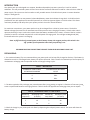
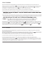
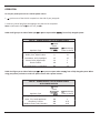
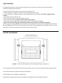
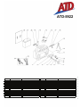
ATD-5922
RECHARGEABLE 12 VOLT 22 AMP/HOUR JUMP START
OWNERS MANUAL
ͻ 1700 peak amps/700 cranking amps of staƌƟŶŐ power.
ͻ Starts cars, trucks, RV’s and boats without the need of another vehicle or AC power cords.
ͻ 12V DC socket with overload protec n provides power for any 12V appliance.
ͻ Provides up to 50-hours of DC power when used with 12V DC appliances.
ͻ Allows 12V DC appliances to be used in remote sites and/or in emergencies when commercial power is not available.
oper on and circuit protec on.
ͻ Solid-state,
ͻ Requires no maintenance for
op
.
ͻ Sealed, maintenance-free, heavy-duty
ery is safe to use and transport.
ͻ Can be stored in any posi on without risking acid leakage.
ͻ 43” heavy-duty 4 gauge copper cables can carry more amperage than similar units.
ͻ Easy to read color coded
ery meter.
ͻ Built-In converter allows recharging from any 120V AC power source.
ͻ DC power cord allows recharging from 12V DC socket.
ͻ
ͻ Heavy-duty impact resistant polyethylene case
cut-oī to prevent overcharging.
ͻ External 120V AC/12V DC charging adapter with an au
ͻ Molded high-impact case is tough and durable.
Made in China to ATD SpeciĮca ons
Visit us at www.atdtools.com
CaliforniaProp65WARNING:
BatteriescontainleadandotherchemicalsknowntotheStateofCaliforniatocausecancer,birthdefectsandother
reproductiveharm.Washhandsafterhandling.
GeneralSafetyWarnings:
WARNING:Theinstructionsandwarningscontainedinthismanualshouldbereadandunderstoodbeforeusing
oroperatingthistool.Donotallowanyonetouseoroperatethistooluntiltheyhavereadthismanualandhave
developedathoroughunderstandingofhowthistoolworks.Failuretoobserveanyofthefollowinginstructionscould
resultinseverepersonalinjurytotooluserandbystanders,orcausedamagetothetoolandproperty.Keepthismanual
forfuturereference.
Note:Thewarningsandcautionsdiscussedinthisinstructionmanualcannotcoverallpossibleconditionsand
situationsthatmayoccur.Itmustbeunderstoodbytheoperatorthatcommonsenseandcautionarefactorswhich
cannotbebuiltintothisproduct,butmustbesuppliedbytheoperator.
WARNING:Usesafetyequipment.Usersandbystandersshouldusesafetygogglesorsafetyglasseswithside
shieldswhichcomplywithcurrentnationalstandards,orwhenneeded,afaceshield.UseanANSIapproveddustmaskor
respiratorwhenworkingaroundmetal,wood,andchemicaldustsandmists.Thisappliestoallpersonsintheworkarea.
AlsousenonͲskidsafetyshoes,hardhat,gloves,dustcollectionsystems,andhearingprotectionwhenappropriate.
WARNING:Keepbystandersandchildrenoutoftheworkareawhileoperatingthistool.
WARNING:Alwayskeepyourworkareaclean,uncluttered,andwelllit.Clutteredordarkareasinviteaccidents
andinjuries.DONOTworkonfloorsurfacesthatareslippery.
WARNING:Donotoperatethistoolifyouaretiredorundertheinfluenceofalcohol,drugs,ormedicationsthat
couldaffectyourabilitytousethetoolproperly.
WARNING:Dressproperly.Donotwearlooseclothingorjeweleryastheycanbecaughtinmovingparts.Wear
restrictivehaircoveringtocontainlonghair.
WARNING:Donotreachoveroracrossrunningmachines.Keepproperfootingandbalanceatalltimes.NonͲ
skidfootwearisrecommendedwhenworking.
LeadAcidBatterySafetyWarnings:
WARNING:WORKINGAROUNDLEADͲACIDBATTERIESMAYBEDANGEROUS.
x
x
x
LeadͲacidbatteriesreleaseexplosivegasesduringnormaloperation,chargingandjumpstarting.
AllleadͲacidbatteries(car,truckandboat)producehydrogengaswhichmayviolentlyexplodeinthepresenceof
fireorsparks.Donotsmoke,usematchesoracigarettelighterwhilenearbatteries.OnlyworkwithleadͲacid
batteriesinawellͲventilatedarea.Donothandlethebatterywhilewearingvinylclothingbecausestatic
electricitysparksaregeneratedwhenvinylclothingisrubbed.
Toreduceriskofbatteryexplosion,followtheseinstructionsandthosepublishedbythebatterymanufacturer
andmanufacturerofanyequipmentyouintendtouseinthevicinityofthebattery.Reviewcautionarymarkings
ontheseproductsandonengine.
EYEPROTECTION:
x Userandbystandersshouldalwaysweareyeprotection,appropriateprotectiveclothingandothersafety
equipmentwhenworkingnearleadͲacidbatteries.DonottoucheyeswhileworkingonoraroundleadͲacid
batteries.
x IFSPLASHEDWITHBATTERYACID,IMMEDIATELYFLUSHAFFECTEDAREASUCHASFACEANDPARTICULARLY
THEEYESWITHCLEANWATER.Seekmedicalattentionandcontinueflushingfaceandeyesuntilmedicalhelp
arrives.
WORKINGINENGINECOMPARTMENT:
x Useextremecautionwhileworkingwithintheenginecompartment,becausemovingpartsmaycausesevere
injury.Readandfollowallsafetyinstructionspublishedinthevehicle’sOwner’sManual.
GENERALPRECAUTIONS/PERSONALPRECAUTIONS:
x NeverworkalonewithleadͲacidbatteries.Makesurethatsomeoneisaroundtogiveassistanceifyouneed
help.
x Wearcompleteeyeprotectionandclothingprotection.Avoidtouchingeyeswhileworkingnearbattery.
x Incaseofbatteryacidcontactwitheyes,skinorclothing,alwayshavesoapandwaternearyourworkarea.
x Removejewelerysuchasrings,bracelets,necklacesandwatcheswhenworkingaroundabattery.AleadͲacid
batterycanproduceashortcircuitcurrent,whichcanmeltmetalsandresultinasevereburn.
x Donotdroptoolsorothermetalobjectsonornearthebatteryasasparkmayresult,ignitingexplosivegases.
x Neverjumpstartorattempttorechargeafrozenbattery.
ElectricalSafetyWarnings:
WARNING:Readallsafetywarningsandinstructions.Failuretofollowallwarningsandinstructionsmayresult
inelectricshock,fireand/orseriousinjuryordeath.
WARNING:Toreducetheriskofelectricshock,DONOTuseindampconditions,onwetsurfaces,orexposeto
rain.Donotpluginthisjumpstartoroperateitwithwethandsorwhilestandinginwater.
WARNING:Neverusethecordsorcablesforcarrying,pullingorunpluggingyourjumpstart.Graspplugandpull
todisconnectchargerfromoutlet.Keepcordawayfromheat,oil,sharpedgesormovingparts.Replacedamagedcords
immediately.
WARNING: Always remove the charger from the electric outlet when making adjustments, changing parts,
cleaning or working on the tool.
WARNING:
Care should be taken to arrange the cords and cables so they will not be stepped on, tripped over, or
otherwise subjected to damage or stress.
WARNING:
Never
pt to plug in or operate equipment with
or damaged wires, charger cord or
or damaged parts replaced immediately by ƋƵĂůŝĮed personnel.
charger cord plug. Have any defe
WARNING:
Avoid body contact with electrically grounded surfaces. There is an increased risk of electric shock if
your body is grounded.
WARNING:
If the work area is not equipped with a permanently installed Ground Fault Circuit Interrupter outlet
(GFCI), use a plug-in GFCI between the charging cord and the power receptacle.
ATD-5922 ^ƉĞĐŝĮĐ Warnings:
WARNING: Lead-acid ba
generate hydrogen gas during normal opera on. More gas is generated when the
is charging. Hydrogen gas is:
1. Explosive
2. Poisonous to breathe
3. Highly Ňammable
WARNING:
To avoid possible damage that may shorten the units working life, protect this unit from direct
sunlight, direct heat, and /or moisture.
WARNING: This system is designed to be used only on vehicles or boats with 12-volt electrical systems.
WARNING: This system is not designed to be used as a replacement for a vehicle
WARNING: To avoid an explosion and/or the possibility of being splashed with
ery.
acid:
ͻ Never allow the red and black clamps to touch each other or for both to touch the same metal object or any electrically
material for that ma
condu
ͻ Only
pt to jump start a vehicle or boat in a wellated area.
ͻ Always connect the red (+) clamp to the
ve (+) ba
terminal ĮƌƐƚ͘
ͻ Do not connect the black (-) clamp to the ne
(-)
ery terminal.
terminal.
ͻ Connect the black (-) clamp to a non-moving metal part on the engine not to the nega ve (-) ba
INTRODUCTION
Your power pack unit is designed as a compact, durable and portable jump start system for 12 volt DC vehicles
and boats. This self contained system will start most vehicles and boats without the need for a host vehicle or 120V AC
power supply. This system can also be used as a safe, portable source of 12V DC electric power in remote locations
and/or in emergencies.
The power pack unit has an easy to read, color coded battery meter that indicates charge level. A 12V DC socket is
provided for use with appliances that would operate from a vehicles cigarette lighter or 12V DC socket. This allows
maximum portability and utility when your power pack unit is used in remote locations.
For maximum convenience, your power pack unit can be recharged from a 120V AC power source. The built in
500mA recharger/converter has an automatic cut off that prevents over charging the battery. A black rocker switch
operates the built in lamp. A red rocker switch shows the battery condition on the meter. A covered 12V DC socket is
provided, as well as a covered receptacle for a 120V AC power recharging cord. The red light emitting diode (led)
illuminates when the system is recharging.
Note: on/off switch only controls power to the 2 battery clamps. We suggest you keep this switch in the
"off" position for all operations other than jump starting a car.
RECOMMENDATIONS FOR GETTING THE MOST FROM YOUR NEW POWER PACK UNIT
RECHARGING:
1. For maximum battery life, we recommend that your power pack unit be kept fully charged at all times. If the battery is
allowed to remain in a discharged state, battery life will be shortened. Table 1 shows the relationship of the frequency of
use between recharging and the expected number of charge/recharge cycles.
TABLE I. BATTERY LIFE
NUMBER OF JUMP STARTS
BETWEEN RECHARGING
1
5
10
DISCHARGE AND RECHARGE
CYCLES
1000+
700+
500+
2. The time required to fully recharge your power booster after jump starting an engine is a function of how many jump
starts are performed between recharging sessions. Table 2 shows the approximate recharging times you can expect.
Table II. RECHARGING TIMES vs. JUMP STARTS
Number Of
Jump Starts
1
2
3
Recharging Time
(In Hours)
8
16
24
Number Of
Jump Starts
4
5
6
Recharging Time
(In Hours)
32
40
48
3. Check the charge in your power pack unit often by depressing the red push button switch. The meter will show the
battery charge.
120V AC CHARGING:
Plug the 120V AC/12V DC charging adapter into a wall outlet and into the receptacle on your new power pack unit.
Charge this device for at least 4 hours or
l the meter shows a full (14- to 15-V DC) charge when the red rocker switch
is depressed. The recharging converter circuit unit has an automa cut-Žī circuit so the internal
ery cannot be
overcharged. To recharge your power pack unit
ry from 120V AC follow these steps:
1. On the power packs right side, there are two receptacles, one is round and one is rectangular.
2. Pull the plug cover from the rectangular receptacle out, exposing two prongs of a standard 120V AC power cord. A
of your power pack unit.
3. One of the power cords furnished with your power pack has a standard 120V AC male plug at one end, and a rectangular
two prong receptacle at the other end. Plug this power cord into the rectanglular receptacle on the side of the unit and
4.
to charge un l the voltmeter indicates full capacity in green area when the test bu
is pressed.
Important: do not stop charging before the meter indicates full capacity in green area.
At this point, once the charger is disconnected, the voltage will slowly
le back to read 100%. This is quite normal and
indicates that the
ery is at full capacity. Note: to fully charge a
could take up to 72 hours, depending upon the
c
state of discharge. The unit can remain plugged into the power socket inĚĞĮŶitely as the internal PCB has an au
"ŇŽĂƚ charging circuit" which will not allow an overcharge
on or damage to the
ery.
12V DC CHARGING:
Your new power pack unit is equipped with a receptacle that will allow you to re-charge this system from the 12V DC
socket in your vehicle or boat.
ed use of the 12V
Note: We recommend that you use the 12V DC recharging procedure only when necessary, as c
DC recharging procedure may shorten the system's life. To use the 12V DC recharging system:
1. Insert the power cord with the 12V DC plug into the 12V DC receptacle on your vehicle or boat.
2. Insert the plug at the other end of this power cord into the receptacle on the side of your power booster.
the meter shows a full (14- to 15-V DC) charge when the red rocker switch
Charge this device for at least 4 hours o
is depressed. Unlike the AC charging circuit, there is NO FLOATING CHARGE circuit on the DC charging outlet. It is HIGHLY
recommended that DC charging only be used in emergency cases.
OPERATION
To use your power pack unit as a 12V DC power source:
1.
up the cover of the 12V DC receptacle on the side of your jump pack.
2. Insert the 12V DC plug from the appliance into the 12V DC receptacle.
in the ͞Žī” posi on.
Note: on/oī switch can be
Table III will give you an idea of what oper
on me to expect when
ng from a fully charged system:
Table III. - POWER PACK AS A 12V DC POWER SOURCE
Appliance Type
Fluorescent Lights, Cell Phones
Radios, Fans, Depth Finders
Camcorders, VCR's, Spotlights
Electric Tools, Bilge Pumps
Electric Coolers
Air Compressors, Car Vacuums
mated
Power
on
(In
)
4
9
15
24
48
80
mated Usage
Times (In Hours)
30
21
12
7
3
1.5
Table IV will give you an idea of what oper on me you can expect when star ng from a fully charged system. When
using your power pack unit as a 120 v ac power source with a power inverter:
Table IV. - POWER PACK AS A 12V DC POWER SOURCE
WITH POWER INVERTER
Appliance Type
Spotlights, Sump Pumps & VCR's
Faxes, TV's, Small Appliances
Computers, Printers
Medium Power Tools, Blenders
mated
Power
on
)
(In
100
150
200
250
mated Usage
Times (In Hours)
1.5
1
0.75
0.05
JUMPͲSTARTING:
Foroptimumperformance,whenusingyourpowerpackunittojumpstartavehicleorboat,pleasereadand
FollowthesestepͲbyͲstepinstructions:
1.SwitchtheengineofthevehicleorboattobejumpͲstartedto“off”.
2.Connectthered(+)“alligator”clamptothered(+)positivebatteryterminal.
3.Connecttheblack(Ͳ)“alligator”clamptoanonͲmovingmetalpartoftheengine,nottothe(Ͳ)negativebattery
terminal.
4.Turnpowerpackunitswitchto“on”.
5.Waitaminuteortwotoletthevehiclebatterycharge
6.Trytostartthevehiclebutdonottryformorethan5to6seconds.
7.Ifthevehicleorboatenginedoesnotstart,waitatleast3minutesbeforetryingagain.
*undernocircumstancesallowtheredandblackclampstotoucheachotheroracommonconductor*
Oncetheengineisrunning,firstdisconnecttheblack(Ͳ)clampandreturnthiscabletoitsstoredpositiononthepower
packunit,thendisconnectthered(+)clampandreturnthiscabletoitsstoredpositiononthepowerpackunit.Assoon
aspossible,connectyourpowerpackunitsystemto120Ͳvacandrecharge.
BATTERYREPLACEMENT
FIGURE1.ͲRearviewofthepowerpackunitshowingthebatterycompartment
1.UnscrewandremovethePhillipsheadscrewsthatholdtherearcoverinplaceonthebackofyourpowerpackunit.
2.Liftoffthecoverplatetoexposethebatterycompartment.
3.Liftthebatteryoutofthebatterycompartment.
4.Detachthe#4jumpercablesandtheredandblackrechargingwiresfromthebatteryterminals.
5. Ensure tha he replacement
ery came out.
just as the old
ery is oriented with the
ve on the right side and the
6. Connec he red #4 jumper cable and red recharging wire to the
ve (+)
(-)
then connec he black #4 jumper cable and recharging wire to the nega
conne
and ghten.
7. Taking care no o damage the circuit board, slide the new
8. Replace the
on the le side,
terminal (also marked with red),
terminal. Double check all
ery in
ery compartment cover and secure in place with the Phillips head screws.
SPECIFICATIONS
ITEM # . . . . . . . …. . . . . . . . . . . . . . . . . . . .ATD-5922
VOLTAGE . . . . . . . . . . . . . . . . . . . . . . . . . .12V DC
BOOST POWER . . . . . . . . . . . . . . . . . . . . .700 CRANKING AMPS
PEAK AMPS… …...…….. . . .. . . . . . . . . . ….1700 AMPS
BATTERY TYPE . . . . . . . . . . . . . . . . . . . . ..SEALED, LEAD- ACID, RECHARGEABLE, MAINTENANCE-FREE, 12V DC, 22-AMP-HOURS
BOOSTER CABLES . . . . . . . . . . . . . . . . . …43”, #4 GAUGE 100% COPPER CABLES WITH 500 AMP "ALLIGATOR" CLAMPS
DIMENSIONS …. . . . . . . . . . . . . . . . . . .. . 11.8” x 10.6” x 3.5” (30 x 27 x 9 CM)
ATD-5922
ITEM#
1
2
3
4
5
6
7
8
9
10
11
12
ORDERING PART#
PRT5921-01
PRT5921-02
PRT5921-03
PRT5921-04
PRT5921-05
PRT5921-06
PRT5921-07
PRT5921-08
PRT5921-09
PRT5921-10
PRT5921-11
PRT5921-12
PART DESCRIPTION
HOUSING
LABEL
REFLECTOR
BULB SOCKET
BULB
LENS
BEZEL
LIGHTING SWITCH
TEST SWITCH
VOLTMETER
SHORT CABLE ASSY.
JUMP CABLE SET
ITEM#
13
14
15
16
17
18
19
20
21
22
23
24
ORDERING PART#
PRT5922-13
PRT5922-14
PRT5921-15
PRT5921-16
PRT5921-17
PRT5921-18
PRT5921-19
PRT5922-20
ATD5904
PRT5921-22
PRT5922-23-24
PRT5922-23-24
PART DESCRIPTION
COVER
TRANSFORMER 500mA
CIG. LIGHTER SOCKET (INNER)
CAP
CIG. LIGHTER SOCKET (OUTER)
CIRCUIT BREAKER
ON/OFF SWITCH
PCB ASSY.
12V/22AH BATTERY
BACK COVER
AC & DC POWER CORDS
AC & DC POWER CORDS