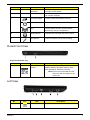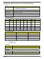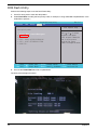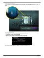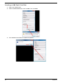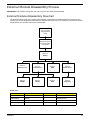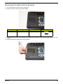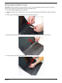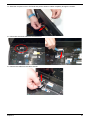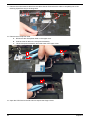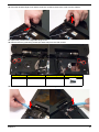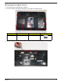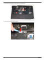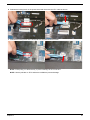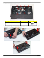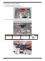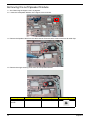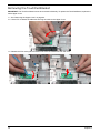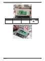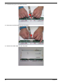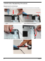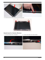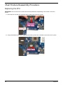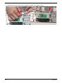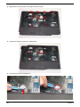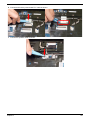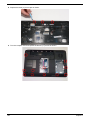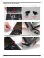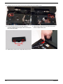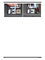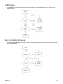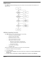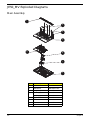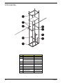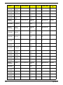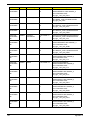
1
Aspire 5334/5734Z Series
Service Guide
Service guide files and updates are available
on the ACER/CSD web; for more information,
please refer to http://csd.acer.com.tw
PRINTED IN TAIWAN
Revision History
Please refer to the table below for the updates made on Aspire 5334 Series service guides.
Date
II
Chapter
Updates
Copyright
Copyright © 2010 by Acer Incorporated. All rights reserved. No part of this publication may be reproduced,
transmitted, transcribed, stored in a retrieval system, or translated into any language or computer language, in
any form or by any means, electronic, mechanical, magnetic, optical, chemical, manual or otherwise, without
the prior written permission of Acer Incorporated.
Disclaimer
The information in this guide is subject to change without notice.
Acer Incorporated makes no representations or warranties, either expressed or implied, with respect to the
contents hereof and specifically disclaims any warranties of merchantability or fitness for any particular
purpose. Any Acer Incorporated software described in this manual is sold or licensed "as is". Should the
programs prove defective following their purchase, the buyer (and not Acer Incorporated, its distributor, or its
dealer) assumes the entire cost of all necessary servicing, repair, and any incidental or consequential
damages resulting from any defect in the software.
Acer is a registered trademark of Acer Corporation.
Intel is a registered trademark of Intel Corporation.
Other brand and product names are trademarks and/or registered trademarks of their respective holders.
III
Conventions
The following conventions are used in this manual:
IV
SCREEN MESSAGES
Denotes actual messages that appear
on screen.
NOTE
Gives bits and pieces of additional
information related to the current
topic.
WARNING
Alerts you to any damage that might
result from doing or not doing specific
actions.
CAUTION
Gives precautionary measures to
avoid possible hardware or software
problems.
IMPORTANT
Reminds you to do specific actions
relevant to the accomplishment of
procedures.
Preface
Before using this information and the product it supports, please read the following general information.
1.
This Service Guide provides you with all technical information relating to the BASIC CONFIGURATION
decided for Acer's "global" product offering. To better fit local market requirements and enhance product
competitiveness, your regional office MAY have decided to extend the functionality of a machine (e.g.
add-on card, modem, or extra memory capability). These LOCALIZED FEATURES will NOT be covered
in this generic service guide. In such cases, please contact your regional offices or the responsible
personnel/channel to provide you with further technical details.
2.
Please note WHEN ORDERING FRU PARTS, that you should check the most up-to-date information
available on your regional web or channel. If, for whatever reason, a part number change is made, it will
not be noted in the printed Service Guide. For ACER-AUTHORIZED SERVICE PROVIDERS, your Acer
office may have a DIFFERENT part number code to those given in the FRU list of this printed Service
Guide. You MUST use the list provided by your regional Acer office to order FRU parts for repair and
service of customer machines.
V
VI
Table of Contents
System Specifications
1
Features . . . . . . . . . . . . . . . . . . . . . . . . . . . . . . . . . . . . . . . . . . . . . . . . . . . . . . . . . . . .1
Optical Media Drive . . . . . . . . . . . . . . . . . . . . . . . . . . . . . . . . . . . . . . . . . . . . . . . .2
System Block Diagram . . . . . . . . . . . . . . . . . . . . . . . . . . . . . . . . . . . . . . . . . . . . . . . . .5
Your Acer Notebook tour . . . . . . . . . . . . . . . . . . . . . . . . . . . . . . . . . . . . . . . . . . . . . . .6
Front View . . . . . . . . . . . . . . . . . . . . . . . . . . . . . . . . . . . . . . . . . . . . . . . . . . . . . . .6
Closed Front View . . . . . . . . . . . . . . . . . . . . . . . . . . . . . . . . . . . . . . . . . . . . . . . . .7
Left View . . . . . . . . . . . . . . . . . . . . . . . . . . . . . . . . . . . . . . . . . . . . . . . . . . . . . . . .7
Right View . . . . . . . . . . . . . . . . . . . . . . . . . . . . . . . . . . . . . . . . . . . . . . . . . . . . . . .9
Bottom View . . . . . . . . . . . . . . . . . . . . . . . . . . . . . . . . . . . . . . . . . . . . . . . . . . . . .9
Indicators . . . . . . . . . . . . . . . . . . . . . . . . . . . . . . . . . . . . . . . . . . . . . . . . . . . . . .10
TouchPad Basics . . . . . . . . . . . . . . . . . . . . . . . . . . . . . . . . . . . . . . . . . . . . . . . .11
Using the Keyboard . . . . . . . . . . . . . . . . . . . . . . . . . . . . . . . . . . . . . . . . . . . . . . . . . .12
Lock Keys and embedded numeric keypad . . . . . . . . . . . . . . . . . . . . . . . . . . . .12
Windows Keys . . . . . . . . . . . . . . . . . . . . . . . . . . . . . . . . . . . . . . . . . . . . . . . . . .13
Hot Keys . . . . . . . . . . . . . . . . . . . . . . . . . . . . . . . . . . . . . . . . . . . . . . . . . . . . . . .14
Hardware Specifications and Configurations . . . . . . . . . . . . . . . . . . . . . . . . . . . . . . .15
System Utilities
23
BIOS Setup Utility . . . . . . . . . . . . . . . . . . . . . . . . . . . . . . . . . . . . . . . . . . . . . . . . . . . .23
Navigating the BIOS Utility . . . . . . . . . . . . . . . . . . . . . . . . . . . . . . . . . . . . . . . . .23
HM52-MV Intel BIOS . . . . . . . . . . . . . . . . . . . . . . . . . . . . . . . . . . . . . . . . . . . . . . . . .24
Information . . . . . . . . . . . . . . . . . . . . . . . . . . . . . . . . . . . . . . . . . . . . . . . . . . . . .24
Main . . . . . . . . . . . . . . . . . . . . . . . . . . . . . . . . . . . . . . . . . . . . . . . . . . . . . . . . . .25
Security . . . . . . . . . . . . . . . . . . . . . . . . . . . . . . . . . . . . . . . . . . . . . . . . . . . . . . . .26
Boot . . . . . . . . . . . . . . . . . . . . . . . . . . . . . . . . . . . . . . . . . . . . . . . . . . . . . . . . . . .29
Exit . . . . . . . . . . . . . . . . . . . . . . . . . . . . . . . . . . . . . . . . . . . . . . . . . . . . . . . . . . .30
BIOS Flash Utilities . . . . . . . . . . . . . . . . . . . . . . . . . . . . . . . . . . . . . . . . . . . . . . . . . . .31
DOS Flash Utility . . . . . . . . . . . . . . . . . . . . . . . . . . . . . . . . . . . . . . . . . . . . . . . . .32
WinFlash Utility . . . . . . . . . . . . . . . . . . . . . . . . . . . . . . . . . . . . . . . . . . . . . . . . . .34
Remove HDD/BIOS Password Utilities . . . . . . . . . . . . . . . . . . . . . . . . . . . . . . . . . . . .35
Machine Disassembly and Replacement
43
Disassembly Requirements . . . . . . . . . . . . . . . . . . . . . . . . . . . . . . . . . . . . . . . . . . . .43
Pre-disassembly Instructions . . . . . . . . . . . . . . . . . . . . . . . . . . . . . . . . . . . . . . .44
Disassembly Process . . . . . . . . . . . . . . . . . . . . . . . . . . . . . . . . . . . . . . . . . . . . .44
External Module Disassembly Process . . . . . . . . . . . . . . . . . . . . . . . . . . . . . . . . . . .45
External Modules Disassembly Flowchart . . . . . . . . . . . . . . . . . . . . . . . . . . . . .45
Removing the Battery Pack . . . . . . . . . . . . . . . . . . . . . . . . . . . . . . . . . . . . . . . .46
Removing the SD Dummy Card . . . . . . . . . . . . . . . . . . . . . . . . . . . . . . . . . . . . .47
Removing the Lower Covers . . . . . . . . . . . . . . . . . . . . . . . . . . . . . . . . . . . . . . . .48
Removing the Optical Drive Module . . . . . . . . . . . . . . . . . . . . . . . . . . . . . . . . . .49
Removing the DIMM Modules . . . . . . . . . . . . . . . . . . . . . . . . . . . . . . . . . . . . . . .51
Removing the WLAN Module . . . . . . . . . . . . . . . . . . . . . . . . . . . . . . . . . . . . . . .52
Removing the Hard Disk Drive Module . . . . . . . . . . . . . . . . . . . . . . . . . . . . . . . .55
Removing the Switch Cover . . . . . . . . . . . . . . . . . . . . . . . . . . . . . . . . . . . . . . . .57
Removing the Keyboard . . . . . . . . . . . . . . . . . . . . . . . . . . . . . . . . . . . . . . . . . . .58
Main Unit Disassembly Process . . . . . . . . . . . . . . . . . . . . . . . . . . . . . . . . . . . . . . . . .59
Main Unit Disassembly Flowchart . . . . . . . . . . . . . . . . . . . . . . . . . . . . . . . . . . . .59
Removing the LCD Module . . . . . . . . . . . . . . . . . . . . . . . . . . . . . . . . . . . . . . . . .60
Removing the Upper Cover . . . . . . . . . . . . . . . . . . . . . . . . . . . . . . . . . . . . . . . .65
Removing the Power Board . . . . . . . . . . . . . . . . . . . . . . . . . . . . . . . . . . . . . . . .69
Removing the Left Speaker Module . . . . . . . . . . . . . . . . . . . . . . . . . . . . . . . . . .70
Removing the TouchPad Bracket . . . . . . . . . . . . . . . . . . . . . . . . . . . . . . . . . . . .72
VII
Table of Contents
Removing the Mainboard . . . . . . . . . . . . . . . . . . . . . . . . . . . . . . . . . . . . . . . . . .74
Removing the RTC Battery . . . . . . . . . . . . . . . . . . . . . . . . . . . . . . . . . . . . . . . . .75
Removing the Thermal Module . . . . . . . . . . . . . . . . . . . . . . . . . . . . . . . . . . . . . .76
Removing the CPU Fan . . . . . . . . . . . . . . . . . . . . . . . . . . . . . . . . . . . . . . . . . . .78
Removing the CPU . . . . . . . . . . . . . . . . . . . . . . . . . . . . . . . . . . . . . . . . . . . . . . .79
LCD Module Disassembly Process . . . . . . . . . . . . . . . . . . . . . . . . . . . . . . . . . . . . . .80
LCD Module Disassembly Flowchart . . . . . . . . . . . . . . . . . . . . . . . . . . . . . . . . .80
Removing the LCD Bezel . . . . . . . . . . . . . . . . . . . . . . . . . . . . . . . . . . . . . . . . . .81
Removing the Camera Module . . . . . . . . . . . . . . . . . . . . . . . . . . . . . . . . . . . . . .82
Removing the Inverter Board . . . . . . . . . . . . . . . . . . . . . . . . . . . . . . . . . . . . . . .83
Removing the LCD Panel . . . . . . . . . . . . . . . . . . . . . . . . . . . . . . . . . . . . . . . . . .84
Removing the LCD Brackets and FPC Cable . . . . . . . . . . . . . . . . . . . . . . . . . . .85
Removing the Antennas . . . . . . . . . . . . . . . . . . . . . . . . . . . . . . . . . . . . . . . . . . .87
LCD Module Reassembly Procedure . . . . . . . . . . . . . . . . . . . . . . . . . . . . . . . . . . . . .90
Replacing the Antennas . . . . . . . . . . . . . . . . . . . . . . . . . . . . . . . . . . . . . . . . . . .90
Replacing the LCD Panel . . . . . . . . . . . . . . . . . . . . . . . . . . . . . . . . . . . . . . . . . .93
Replacing the Camera Module . . . . . . . . . . . . . . . . . . . . . . . . . . . . . . . . . . . . . .94
Replacing the Inverter Board . . . . . . . . . . . . . . . . . . . . . . . . . . . . . . . . . . . . . . .95
Replacing the LCD Bezel . . . . . . . . . . . . . . . . . . . . . . . . . . . . . . . . . . . . . . . . . .96
Main Module Reassembly Procedure . . . . . . . . . . . . . . . . . . . . . . . . . . . . . . . . . . . . .98
Replacing the CPU . . . . . . . . . . . . . . . . . . . . . . . . . . . . . . . . . . . . . . . . . . . . . . .98
Replacing the CPU Fan . . . . . . . . . . . . . . . . . . . . . . . . . . . . . . . . . . . . . . . . . . .99
Replacing the Thermal Module . . . . . . . . . . . . . . . . . . . . . . . . . . . . . . . . . . . . . .99
Replacing the Mainboard . . . . . . . . . . . . . . . . . . . . . . . . . . . . . . . . . . . . . . . . .100
Replacing the TouchPad Bracket . . . . . . . . . . . . . . . . . . . . . . . . . . . . . . . . . . .101
Replacing the Left Speaker Module . . . . . . . . . . . . . . . . . . . . . . . . . . . . . . . . .103
Replacing the Power Board . . . . . . . . . . . . . . . . . . . . . . . . . . . . . . . . . . . . . . .103
Replacing the Upper Cover . . . . . . . . . . . . . . . . . . . . . . . . . . . . . . . . . . . . . . . .105
Replacing the LCD Module . . . . . . . . . . . . . . . . . . . . . . . . . . . . . . . . . . . . . . . .109
Replacing the Keyboard . . . . . . . . . . . . . . . . . . . . . . . . . . . . . . . . . . . . . . . . . .114
Replacing the Switch Cover . . . . . . . . . . . . . . . . . . . . . . . . . . . . . . . . . . . . . . .115
Replacing the Hard Disk Drive Module . . . . . . . . . . . . . . . . . . . . . . . . . . . . . . .115
Replacing the WLAN Module . . . . . . . . . . . . . . . . . . . . . . . . . . . . . . . . . . . . . .117
Replacing the DIMM Modules . . . . . . . . . . . . . . . . . . . . . . . . . . . . . . . . . . . . . .119
Replacing the ODD Module . . . . . . . . . . . . . . . . . . . . . . . . . . . . . . . . . . . . . . .119
Replacing the Lower Covers . . . . . . . . . . . . . . . . . . . . . . . . . . . . . . . . . . . . . . .120
Replacing the SD Dummy Card . . . . . . . . . . . . . . . . . . . . . . . . . . . . . . . . . . . .120
Replacing the Battery . . . . . . . . . . . . . . . . . . . . . . . . . . . . . . . . . . . . . . . . . . . .121
Troubleshooting
123
Common Problems . . . . . . . . . . . . . . . . . . . . . . . . . . . . . . . . . . . . . . . . . . . . . . . . . .123
Power On Issue . . . . . . . . . . . . . . . . . . . . . . . . . . . . . . . . . . . . . . . . . . . . . . . .124
No Display Issue . . . . . . . . . . . . . . . . . . . . . . . . . . . . . . . . . . . . . . . . . . . . . . . .125
Random Loss of BIOS Settings . . . . . . . . . . . . . . . . . . . . . . . . . . . . . . . . . . . .126
LCD Failure . . . . . . . . . . . . . . . . . . . . . . . . . . . . . . . . . . . . . . . . . . . . . . . . . . . .127
Built-In Keyboard Failure . . . . . . . . . . . . . . . . . . . . . . . . . . . . . . . . . . . . . . . . .127
TouchPad Failure . . . . . . . . . . . . . . . . . . . . . . . . . . . . . . . . . . . . . . . . . . . . . . .128
Internal Speaker Failure . . . . . . . . . . . . . . . . . . . . . . . . . . . . . . . . . . . . . . . . . .128
HDD Not Operating Correctly . . . . . . . . . . . . . . . . . . . . . . . . . . . . . . . . . . . . . .130
ODD Failure . . . . . . . . . . . . . . . . . . . . . . . . . . . . . . . . . . . . . . . . . . . . . . . . . . .131
Wireless Function Failure . . . . . . . . . . . . . . . . . . . . . . . . . . . . . . . . . . . . . . . . .134
Thermal Unit Failure . . . . . . . . . . . . . . . . . . . . . . . . . . . . . . . . . . . . . . . . . . . . .134
External Mouse Failure . . . . . . . . . . . . . . . . . . . . . . . . . . . . . . . . . . . . . . . . . . .135
Other Failures . . . . . . . . . . . . . . . . . . . . . . . . . . . . . . . . . . . . . . . . . . . . . . . . . .135
Intermittent Problems . . . . . . . . . . . . . . . . . . . . . . . . . . . . . . . . . . . . . . . . . . . . . . . .136
VIII
Table of Contents
Undetermined Problems . . . . . . . . . . . . . . . . . . . . . . . . . . . . . . . . . . . . . . . . . . . . . .136
Post Codes . . . . . . . . . . . . . . . . . . . . . . . . . . . . . . . . . . . . . . . . . . . . . . . . . . . . . . . .137
Jumper and Connector Locations
145
Top View . . . . . . . . . . . . . . . . . . . . . . . . . . . . . . . . . . . . . . . . . . . . . . . . . . . . . .145
Bottom View . . . . . . . . . . . . . . . . . . . . . . . . . . . . . . . . . . . . . . . . . . . . . . . . . . .146
Power Board . . . . . . . . . . . . . . . . . . . . . . . . . . . . . . . . . . . . . . . . . . . . . . . . . . .147
Clearing Password Check and BIOS Recovery . . . . . . . . . . . . . . . . . . . . . . . . . . . .148
Clearing Password Check . . . . . . . . . . . . . . . . . . . . . . . . . . . . . . . . . . . . . . . . .148
Clear CMOS Jumper . . . . . . . . . . . . . . . . . . . . . . . . . . . . . . . . . . . . . . . . . . . . .149
BIOS Recovery by Crisis Disk . . . . . . . . . . . . . . . . . . . . . . . . . . . . . . . . . . . . .150
FRU (Field Replaceable Unit) List
151
JE50_MV Exploded Diagrams . . . . . . . . . . . . . . . . . . . . . . . . . . . . . . . . . . . . . . . . .152
Main Assembly . . . . . . . . . . . . . . . . . . . . . . . . . . . . . . . . . . . . . . . . . . . . . . . . .152
Rear Assembly . . . . . . . . . . . . . . . . . . . . . . . . . . . . . . . . . . . . . . . . . . . . . . . . .153
LCD Assembly . . . . . . . . . . . . . . . . . . . . . . . . . . . . . . . . . . . . . . . . . . . . . . . . .154
JE50_MV FRU List . . . . . . . . . . . . . . . . . . . . . . . . . . . . . . . . . . . . . . . . . . . . . . . . . .155
Screw List . . . . . . . . . . . . . . . . . . . . . . . . . . . . . . . . . . . . . . . . . . . . . . . . . . . . . . . . .163
Model Definition and Configuration
164
Test Compatible Components
219
Microsoft® Windows® 7 Environment Test . . . . . . . . . . . . . . . . . . . . . . . . . . . . . . .220
Online Support Information
233
Index
235
IX
Table of Contents
X
Chapter 1
System Specifications
Features
Below is a brief summary of the computer’s many features:
NOTE: Items denoted with an (*) are only available for selected models.
Operating System
•
Genuine Windows® 7 Home Premium 64-bit
•
Genuine Windows® 7 Home Basic 64-bit
Platform
Aspire 5334
•
Intel® Celeron® processor T3100/T3000 (1 MB L2 cache, 1.80/1.90 GHz, 800 MHz FSB, 35 W),
T1600/T1700 (1 MB L2 cache, 1.66/1.83 GHz, 667 MHz FSB, 35 W), supporting Intel® 64
architecture
•
Intel® Celeron® processor 900 (1 MB L2 cache, 2.20 GHz, 800 MHz FSB, 35 W), supporting
Intel® 64 architecture
•
Mobile Intel® GL40 Express Chipset
Aspire 5734Z
•
Intel® Pentium® processor T4200/T4300/T4400/T4500 (1 MB L2 cache, 2/2.10/2.20/2.30 GHz,
800 MHz FSB, 35 W), supporting Intel® 64 architecture
•
Mobile Intel® GL40 Express Chipset
System Memory
•
Dual-channel DDR3 SDRAM support:
•
Up to 2 GB of DDR3 system memory, upgradable to 4 GB using two soDIMM modules
Display
•
15.6” WXGA, HD 720p, 1366x768
•
16:9 aspect ratio
Graphics
•
Mobile Intel® GL40 Express Chipset with integrated 3D graphics, featuring Intel® Graphics Media
Accelerator 4500M (Intel® GMA 4500M) with up to 1759 MB of Intel® Dynamic Video Memory
Technology 5.0 (64 MB of dedicated system memory, up to 1695 MB of shared system memory),
supporting Microsoft® DirectX® 10
•
Dual independent display support
•
16.7 million colors
•
External resolution / refresh rates:
•
MPEG-2/DVD decoding
•
WMV9 (VC-1) and H.264 (AVC) decoding
•
Chapter 1
VGA port up to 2560 x 1600: 60 Hz
1
Audio
•
One built-in mono speaker
•
Built-in microphone
•
MS-Sound compatible
Storage subsystem
Aspire 5334/5734Z
•
Hard disk drive: 160/250/320/500/640 GB or larger
Aspire 5734Z
•
Multi-in-1 card reader, supporting Secure Digital™ (SD), MultiMediaCard (MMC), Memory Stick™
(MS), Memory Stick PRO™ (MS PRO), xD-Picture Card™ (xD)
Optical Media Drive
•
8X DVD-Super Multi double-layer drive:
•
Read: 24X CD-ROM, 24X CD-R, 24X CD-RW, 8X DVD-ROM, 8X DVD-R, 8X DVD+R, 6X
DVD-ROM DL, 6X DVD-R DL, 6X DVD+R DL, 6X DVD-RW, 6X DVD+RW, 5X DVD-RAM
•
Write: 24X CD-R, 16X CD-RW, 8X DVD-R, 8X DVD+R, 4X DVD-R DL, 4X DVD+R DL, 6X
DVD-RW, 8X DVD+RW, 5X DVD-RAM
Dimensions and Weight
•
372.3 (W) x 246.5 (D) x 26.8/39.6 (H) mm (14.51 x 9.61 x 1.04/1.54 inches)
•
2.7 kg (6.0 lbs.) with 6-cell battery pack
Communication
Webcam
•
Acer Crystal Eye webcam with 1280 x 1024 resolution
•
Microphone
WLAN
•
802.11 b/g/n Wi-Fi CERTIFIED™
•
802.11 b/g Wi-Fi CERTIFIED™
•
10/100 Mbps Fast Ethernet
LAN
Privacy control
2
•
BIOS user, supervisor, HDD passwords
•
Kensington lock slot
Chapter 1
Power subsystem
ACPI 3.0 CPU power management standard: supports Standby and Hibernation power-saving modes
Adapter:
•
3-pin 65 W AC adapter:
•
108 (W) x 46 (D) x 29.5 (H) mm (4.25 x 1.81 x 1.16 inches)
•
225 g (0.49 lbs.) with 180 cm DC cable
Battery:
•
48.8 W 4400 mAh 6-cell Li-ion battery pack
•
Battery life: 3.0 hours
•
ENERGY STAR®
Special keys and controls
•
99-/100-/103-key keyboard with inverted "T" cursor layout
•
Touchpad pointing device
•
8 function keys, four cursor keys, two Windows® keys, independent numeric keypad, international
language support
•
Easy-launch keys: touchpad lock, communication
•
Media control keys (printed on keyboard): play/pause, stop, previous, next
I/O interface
•
Two USB 2.0 ports
•
External display (VGA) port
•
Headphone/speaker/line-out jack
•
Microphone-in jack
•
Ethernet (RJ-45) port
•
DC-in jack for AC adapter
Aspire 5734Z
•
Multi-in-1 card reader (SD™, MMC, MS, MS PRO, xD)
Software
Productivity
Chapter 1
•
Acer Backup Manager
•
Acer ePower Management
•
Acer eRecovery Management
•
Microsoft® Office Personal 2007 (Service Pack 2) (Japan only, subject to customer request)
•
Microsoft® Office Trial (Service Pack 2)
•
Microsoft® Works SE 9 (Brazil, Canada, France, Germany, Poland, Russia, UK and US only)
•
Microsoft® Works 9
•
Microsoft® Works 8.5
•
Adobe® Flash® Player 10
•
Adobe® Reader® 9.1
•
eSobi™
•
Google Toolbar™
•
Norton™ Online Backup
3
Security
•
McAfee® Internet Security Suite Trial
•
MyWinLocker® (except China, Hong Kong)
Multimedia
•
Cyberlink® PowerDVD™
•
NTI Media Maker™
Gaming
•
Oberon GameZone (except US, Canada, Hong Kong, Korea)
•
WildTangent® (US, Canada only)
Communication and ISP
•
Acer Crystal Eye
•
Microsoft® Silverlight™
•
Windows Live™ Essentials - Wave 3.2 (Mail, Photo Gallery, Live™ Messenger, Movie Maker,
Writer)
•
Skype™
Web links and utilities
•
Acer Accessory Store (Belgium, France, Germany, Italy, Netherlands, Spain, Sweden, UK only)
•
Acer Assist
•
Acer Identity Card
•
Acer Registration
•
Acer Updater
•
eBay® shortcut 2009 (Canada, France, Germany, Italy, Mexico, Spain, UK, US only)
•
Netflix shortcut (US only)
Optional Items
•
1 GB / 2 GB DDR3 soDIMM module
•
3-pin 65 W AC adapter
•
6-cell Li-ion battery pack
•
External USB floppy disk drive
Environment
•
•
4
Temperature:
•
Operating: 5 °C to 35 °C
•
Non-operating: -20 °C to 65 °C
Humidity (non-condensing):
•
Operating: 20% to 80%
•
Non-operating: 20% to 80%
Chapter 1
System Block Diagram
Chapter 1
5
Your Acer Notebook tour
Front View
No.
6
Icon
Item
Description
1
Acer Crystal Eye
webcam
Web camera for video communication
(for selected models).
2
Display screen
Also called Liquid-Crystal Display (LCD),
displays computer output.
3
Speaker
Delivers audio output.
4
Keyboard
For entering data into your computer.
5
Touchpad
Touch-sensitive pointing device which
functions like a computer mouse.
6
Power indicator
Indicates the computer’s power status.
Battery indicator
Indicates the computer's battery status.
1. Charging: The light shows amber when the
battery is charging.
2. Fully charged: The light shows green when
in AC mode.
Chapter 1
No.
Icon
Item
Description
7
Click buttons (left
and right)
The left and right buttons function like the left
and right mouse buttons.
8
Palmrest
Comfortable support area for your hands when
you use the computer.
9
Touchpad toggle
Turns the internal touchpad on and off.
Power button
Turns the computer on and off.
Communication
key
Enables/disables the computer’s
communication devices. (Communication
devices may vary by configuration.)
10
HDD indicator
Indicates when the hard disk drive is active.
11
Microphone
Internal microphone for sound recording.
Closed Front View
Aspire 5734Z model only
No.
Icon
1
Item
5-in-1 card
reader
Description
Accepts Secure Digital (SD), MultiMediaCard
(MMC), Memory Stick (MS), Memory Stick
PRO (MS PRO), xDPicture Card (xD).
NOTE: Push to remove/install the card.
Only one card can operate at any
given time.
Left View
No.
1
Chapter 1
Icon
Item
DC-in jack
Description
Connects to an AC adapter
7
No.
8
Icon
Item
Description
2
Ethernet (RJ-45)
port
Connects to an Ethernet 10/100-based
network.
3
External display
(VGA) port
Connects to a display device
(e.g. external monitor, LCD projector).
4
USB 2.0 ports
Connect to USB 2.0 devices (e.g. USB mouse,
USB camera).
5
Microphone-in
jack
Accepts input from external microphones.
Headphones/
speaker/line-out
jack
Connects to audio line-out devices
(e.g. speakers, headphones).
Chapter 1
Right View
No.
Item
Description
1
Optical drive
Internal optical drive; accepts CDs or DVDs.
2
Optical disk access
indicator
Lights up when the optical drive is active.
3
Optical drive eject button
Ejects the optical disk from the drive.
4
Emergency eject hole
Ejects the optical drive tray when the computer is turned
off.
Note: Insert a paper clip into the emergency eject hole to
eject the optical drive tray when the computer is off.
5
Kensington lock slot
Connects to a Kensington-compatible computer security
lock.
Note: Wrap the computer security lock cable around an
immovable object such as a table or handle of a locked
drawer. Insert the lock into the notch and turn the key to
secure the lock. Some keyless models are also available.
Bottom View
1
6
5
2
3
4
No.
1
Chapter 1
Icon
Item
Battery bay
Description
Houses the computer's battery pack.
9
No.
Icon
Item
Description
2
Battery release
latch
Releases the battery for removal.
3
Memory
compartment
Houses the computer's main memory.
4
Hard disk bay
Houses the computer's hard disk (secured
with screws).
5
Battery lock
Locks the battery in position.
6
Ventilation slots
and cooling fan
Enable the computer to stay cool, even after
prolonged use.
Note: Do not cover or obstruct the fan opening.
Indicators
The computer has several easy-to-read status indicators. The front panel indicators are visible even when the
computer cover is closed.
Icon
10
Function
Description
Power
Indicates the computer's power status.
Battery
Indicates the computer's battery status.
NOTE: 1. Charging: The light shows amber when
the battery is charging. 2. Fully charged: The light
shows green when in AC mode.
HDD
Indicates when the hard disk drive is active.
Num Lock
Lights up when Num Lock is activated.
Caps Lock
Lights up when Caps Lock is activated.
Chapter 1
TouchPad Basics
The following items show you how to use the TouchPad:
•
Move your finger across the TouchPad (1) to move the cursor.
•
Press the left (2) and right (3) buttons located beneath the TouchPad to perform selection and
execution functions. These two buttons are similar to the left and right buttons on a mouse.
Tapping on the TouchPad is the same as clicking the left button.
Function
Execute
Left Button (2)
Right Button (3)
Quickly click twice.
Main TouchPad (1)
Tap twice (at the same speed
as double-clicking a mouse
button).
Select
Click once.
Tap once.
Drag
Click and hold, then use
finger on the TouchPad to
drag the cursor.
Tap twice (at the same speed
as double-clicking a mouse
button); rest your finger on
the TouchPad on the second
tap and drag the cursor.
Access
context menu
Click once.
NOTE: When using the TouchPad, keep it - and your fingers - dry and clean. The TouchPad is sensitive to
finger movement; hence, the lighter the touch, the better the response. Tapping too hard will not
increase the TouchPad’s responsiveness.
Chapter 1
11
Using the Keyboard
The keyboard has full-sized keys and an embedded numeric keypad, separate cursor, lock, Windows, function
and special keys.
Lock Keys and embedded numeric keypad
The keyboard has two lock keys which you can toggle on and off.
Lock key
Description
Caps Lock
When Caps Lock is on, all alphabetic characters typed are in uppercase.
Num Lock
When Num Lock is on, the embedded keypad is in numeric mode. The keys
function as a calculator (complete with the arithmetic operators +, -, *, and /). Use
this mode when you need to do a lot of numeric data entry. A better solution
would be to connect an external keypad.
The embedded numeric keypad functions like a desktop numeric keypad. It is indicated by small characters
located on the upper right corner of the keycaps. To simplify the keyboard legend, cursor-control key symbols
are not printed on the keys.
Desired access
12
Num Lock on
Num Lock off
Number keys on
embedded keypad
Type numbers in a normal manner.
Cursor-control keys on
embedded keypad
Hold <Shift> while using cursorcontrol keys.
Hold <Fn> while using cursorcontrol keys.
Main keyboard keys
Hold <Fn> while typing letters on
embedded keypad.
Type the letters in a normal
manner.
Chapter 1
Windows Keys
The keyboard has two keys that perform Windows-specific functions.
Key
Description
Windows key Pressed alone, this key has the same effect as clicking on the Windows Start button;
it launches the Start menu. It can also be used with other keys to provide a variety of
functions:
<
>:
<
>
+ <D>: Display the desktop
<
>
+ <E>: Open Windows Explore
<
>
+ <F>: Search for a file or folder
<
>
+ <G>: Cycle through Sidebar gadgets
<
>
+ <L>: Lock your computer (if you are connected to a network domain), or
switch users (if you're not connected to a network domain)
<
>
+ <M>: Minimizes all windows
<
>
+ <R>: Open the Run dialog box
<
>
+ <T>: Cycle through programs on the taskbar
<
>
+ <U>: Open Ease of Access Center
<
>
+ <X>: Open Windows Mobility Center
<
>
+ <BREAK>: Display the System Properties dialog box
<
>
+ <SHIFT+M>: Restore minimized windows to the desktop
<
>
+ <TAB>: Cycle through programs on the taskbar by using Windows Flip 3-D
<
>
+ <SPACEBAR>: Bring all gadgets to the front and select Windows Sidebar
Open or close the Start menu
<CTRL> + <
>
<CTRL> + <
>
+ <F>: Search for computers (if you are on a network)
+ <TAB>: Use the arrow keys to cycle through programs on the
taskbar by using Windows Flip 3-D
Note: Depending on your edition of Windows 7, some shortcuts may not function as
described.
Application
key
Chapter 1
This key has the same effect as clicking the right mouse button; it opens the
application's context menu.
13
Hot Keys
The computer employs hotkeys or key combinations to access most of the computer’s controls like screen
brightness, volume output and the BIOS utility.
To activate hot keys, press and hold the <Fn> key before pressing the other key in the hotkey combination.
Hotkey
14
Icon
Function
Description
<Fn> + <F3>
Communication key
Enables/disables the computer’s communication
devices. (Communication devices may vary by
configuration.)
<Fn> + <F4>
Sleep
Puts the computer in Sleep mode.
<Fn> + <F5>
Display toggle
Switches display output between the display
screen, external monitor (if connected) and both.
<Fn> + <F6>
Screen blank
Turns the display screen backlight off to save
power. Press any key to return.
<Fn> + <F7>
Touchpad toggle
Turns the internal touchpad on and off.
<Fn> + <F8>
Speaker toggle
Turns the speakers on and off.
<Fn> +<F9>
Play/Pause
Play or pause a selected media file.
<Fn> + <F10>
Stop
Stop playing the selected media file.
<Fn> +<F11>
Previous
Return to the previous media file.
<Fn> + <F12>
Next
Jump to the next media file.
Brightness up
Increases the screen brightness.
Brightness down
Decreases the screen brightness.
Volume up
Increases the sound volume.
Volume down
Decreases the sound volume.
<Fn> + <
>
<Fn> + <
>
<Fn> + <
>
<Fn> + <
>
Chapter 1
Hardware Specifications and Configurations
Processor
Item
Specification
CPU
•
Intel® Pentium® mobile processor*
•
Intel® Celeron® mobile processor*
Type
Intel Mobile PDC uPGA -478
Core Logic
Mobile Intel® GL40/GM45 Express Chipset
CPU Package
Micro uPGA-478 Package
Power
65 Watts
On-die Cache
4MB L2 cache
Front Side Bus
667/800/1066MHz
Processor Specifications
CPU
Speed
Item
Cores
Bus
Speed
Mfg
Tech
Cache
Size
Package
Core
Voltage
Acer P/N
T1700
1.83 GHz
2
667 MHz
65 nm
1 MB
PGA
1.075V1.175V
KC.17001.CMT
T3000
1.80 GHz
2
800 MHz
45 nm
1 MB
PGA
0.951.30V
KC.30001.CMT
T3100
1.90 GHz
2
800 MHz
45 nm
1 MB
PGA
0.951.30V
KC.31001.CMT
CM900
2.2 GHz
2
800 MHz
N/A
1 MB
PGA
N/A
KC.N0001.900
PMDT4300
2.10 GHz
2
800 MHz
N/A
1 MB
PGA
N/A
KC.34001.DTP
PMDT4400
2.20 GHz
2
800 MHz
N/A
1 MB
PGA
N/A
KC.42001.DTP
PMDT4500
2.30 GHz
2
800 MHz
N/A
1 MB
PGA
N/A
KC.45001.DTP
CPU Fan True Value Table
Fan On Temp (°C)
Fan Speed (rpm)
SPL Spec (dBA)
45
3000
28
50
3300
31
55
3700
34
65
4100
37
75
4500
40
80
4500
40
•
Throttling 50%: On=99°C, Off=96°C
•
OS Shutdown: 105°C
•
H/W Shutdown: 110°C
Northbridge
Item
Specification
Chipset
Intel Cantiga GM45/GL40
Package
uFCBGA-1329
Southbridge
Item
Specification
Chipset
ICH9-M
Package
BGA-676
Chapter 1
15
BIOS
Item
Specification
BIOS vendor
Insyde BIOS
BIOS Version
V0.06-T02
BIOS ROM type
Flash
Features
•
Flash ROM 1MB
•
Supports ISIPP
•
Supports Acer UI
•
Supports multi-boot
•
Suspend to RAM (S3)/Disk (S4)
•
Various hot-keys for system control
•
Supports SMBUS 2.0, PCI2.3
•
ACPI 2.0 compliance with Intel Speed Step support C1, C2,
C3, C4 and S3, S4 for mobile CPU
•
DMI utility for BIOS serial number configurable/asset tag
•
Supports PXE
•
Supports Y2K solution
•
Supports Win Flash Wake on LAN from S3
•
Wake on LAN form S4 in AC mode
•
System information
System Memory
Item
16
Specification
Memory controller
ICH9-M
Memory size
4GB maximum
DIMM socket number
2
Supports memory size per socket
2GB
Supports maximum memory size
4GB (total)
Supports DIMM type
204-pin +1.5V DDRIII
Supports DIMM Speed
800/1066 MHz
Supports DIMM voltage
1.5V
Chapter 1
Memory Combinations
Slot 1
Slot 2
Total Memory
0MB
512MB
512MB
0MB
1024MB
1024MB
0MB
2048MB
2048MB
512MB
512MB
1024MB
512MB
1024MB
1536MB
512MB
2048MB
2560MB
1024MB
0MB
1024MB
1024MB
512MB
1536MB
1024MB
1024MB
2048MB
1024MB
2048MB
3072MB
2048MB
0MB
2048MB
2048MB
512MB
2560MB
2048MB
1024MB
3072MB
2048MB
2048MB
4096MB
NOTE: Above table lists some system memory configurations. You may combine DIMMs with various
capacities to form other combinations. On above table, the configuration of slot 1 and slot 2 could be
reversed.
LAN Interface
Item
Specification
LAN Chipset
Atheros AR8132L
LAN connector type
RJ-45
LAN connector location
Right side
Feature
Support for 10/100
Wireless Module 802.11b/g/Draft-N
Item
Manufacturer
Features
Chapter 1
Specification
•
Foxconn FOX ATH XB63 Foxconn Atheros XB63
minicard b/g
•
Foxconn Wireless LAN Broadcom 4312 minicard b/g
•
Mini PCIe WLAN module with dual-band, built-in
antenna
•
Acer InviLink™ 802.11b/g/Draft-N*
•
Acer InviLink™ 802.11b/g*
17
Hard Disk Drive Interface
Item
Specification
Vendor & Model
Name
Seagate
ST9500325AS
ST9250315AS
Seagate
ST9320320AS
ST9160310AS
Toshiba
MK3255GSX
MK2555GSX
MK1655GSX
Western Digital
WD5000BEVT
WD3200BEVT
WD2500BEVT
WD1600BEVT
Capacity (MB)
500, 250
320, 160
320, 250, 160
500, 320, 250,
160
Bytes per sector
512
512
512
512
Data heads
4, 2
4, 2
4, 2, 2
4, 4, 3, 2
Disks
2, 1
2 or 1, 1
2, 1, 1
2, 2, 2, 1
Spindle speed
(RPM)
5400
5400
5400
5400
Drive Format
Performance Specifications
Buffer size
8 MB
8 MB
Interface
SATA
8 MB
8 MB
SATA
SATA
SATA
Internal transfer
rate (Mbits/sec,
max)
352
395~952 (typical)
850 Mbits/s
maximum
I/O data transfer
rate
(Mbytes/sec
max)
150
300
300 maximum
DC Power Requirements
Voltage
tolerance
18
5V ±5%
5V ±5%
5V ±5%
5V ±5%
Chapter 1
Super-Multi Drive Module
Item
Specification
Vendor & model name HLDS GT20N
Performance
Specification
With CD Diskette
Transfer rate (MB/sec) Sustained:
3,600 KB/s (24x)
max.
Buffer Memory
Sony AD7580S
With DVD Diskette
With CD Diskette
With DVD Diskette
Sustained:
11.08 Mbytes/s (8x)
max.
Sustained:
1,571 (typical)
Sustained:
10,993 (typical)
2 MB
Interface
SATA
Applicable disc
formats
DVD-ROM:
4.7GB (Single Layer)
8.5GB (Dual Layer)
DVD-R:
3.95GB (Ver. 1.0: read only)
4.7GB (Ver. 2.0 for Authoring: read only)
4.7GB (Ver. 2.1 for General: read & write)
(DL) 8.5GB (Ver. 3.0)
DVD-RW:
4.7GB (Ver. 1.2/ Rev 1.0, 2.0, 3.0)
DVD-RAM: 1.46GB/side, 4.7GB/side (Ver.
2.2)
DVD+R: 4.7GB (Ver. 1.3)
(DL) 8.5GB (Ver. 1.1)
DVD+RW:
4.7GB (Vol.1 Ver.1.3)
DVD Read:
DVD-ROM (DVD-5, DVD-9, DVD-10, DVD-18),
DVD-Video, DVD-Audio, SACD (Hybrid),
UDF DVD, DVD-R, DVD-R DL, DVD-R 3.95
GB, DVD-R Authoring, DVD-R Multi-Border,
DVD-RW, DVD+R, DVD+R DL, DVD+R MultiSession, DVD+RW, DVD-RAM V1.0, DVDRAM
V2.0 & 2.1 &2.2.
CD Read:
CD-DA, CD-ROM Mode-1, CD-ROM/XA Mode2 Form-1 and Mode-2 Form-2, CD-i, CD-i
Bridge, Video-CD (MPEG-1), Karaoke CD,
Photo-CD, Enhanced CD, CD Plus, CD Extra,
itrax
CD, CD-Text, UDF CD, CD-R, and CD-RW
CD-ROM Mode-1 data disc
CD-ROM Mode-2 data disc
CD-ROM XA, CD-I, Photo-CD MultiSession, Video CD
CD-Audio Disc
Mixed mode CD-ROM disc (data and audio)
CD-Extra
CD-Text
CD-R (Conforming to “Orange Book Part 2”:
read & write)
CD-RW (Conforming to “Orange Book Part
3”: read & write)
Loading mechanism
Drawer (Solenoid Open)
Tact SW (Open)
Emergency Release (draw open hole)
Input Voltage
DC 5 V +/- 5%
DVD Write:
DVD Data & Video
CD Read:
CD-DA, CD-ROM Mode-1, CD-ROM/XA Mode2 Form-1 and Mode-2 Form-2, CD-i, VideoCD, CD-Text
Power Requirement
Audio Interface
Item
Specification
Chipset
Realtek ALC272X-GR
Features
•
High Definition Audio Codec with Dolby Digital Live
•
One built-in mono speaker
•
Built-in microphone
•
MS-Sound compatible
Chapter 1
19
Power and Keyboard Controller
Item
Specification
Controller
ENE KB926
Total number of keypads
99-/100-/103-key keyboard
Windows logo key
Yes
Hotkeys
See “Hot Keys” on page 14.
Battery
Specification
Item
6 Cell
Vendor & model name
SANYO/SONY/PANASONIC/SAMSUNG/SIMPLO AS2009A
Battery Type
Li-ion
Pack capacity
4400 mAh
Normal Voltage
2.2 Ah
Package configuration
3S2P
LCD 17”
Item
Specification
Vendor/model name
CMO N173O6-L02
Screen Diagonal (mm)
439.4
Display Area (mm)
382.08 x 214.92
Display resolution (pixels)
1600 x 900
Pixel Pitch
0.2388
Display Mode
Typical White Luminance (cd/m
(also called Brightness)
220
Contrast Ratio
600:1
Response Time (Optical Rise
Time/Fall Time) msec
8
Typical Power Consumption
(watt)
7
Weight
580 max.
Physical Size (mm)
398.1 x 232.8 x 5.5
Electrical Interface
LVDS
Support Color
262K
Viewing Angle (up/down/right/
left)
20/45/45/45
Temperature Range (°C)
Operating
Storage (shipping)
20
Normal
2)
0 to +50
-20 to +60
Chapter 1
LCD Display Supported Resolution
Resolution
18 bits
Resolution
18 bits
640x480p/60Hz 4:3
Yes
720x576p/50Hz 4:3
Yes
720x480p/60Hz 4:3
Yes
720x576p/50Hz 16:9
Yes
720x480p/60Hz 16:9
Yes
1280x720p/50Hz 16:9
Yes
1280x720p/60Hz 16:9
Yes
1440x576i/50Hz 4:3
Yes
1440x480i/60Hz 4:3
Yes
1440x576i/50Hz 16:9
Yes
1440x480i/60Hz 16:9
Yes
USB Port
Item
Specification
USB Compliance Level
2.0
OHCI
USB 1.1 and USB 2.0 Host controller
Number of USB Ports
2
Location
Left side
AC Adapter
Item
Specification
Input rating
100V~240V
Maximum input AC current
1.7A
Inrush current
No damage; meet fuse and bridge diode I²t de-rating specified
when 264V (Cool/Hot Start)
Efficiency
1. 84% min. at nominal input voltage, maximum load and measured
at the end of DC cable
2. More than 87% of average efficiency of 25% 50% 75% and 100%
load tested at 115Vac and 230Vac(Warm up after 30 minutes)
Chapter 1
21
System Power Management
Item
22
Specification
Mech. Off (G3)
Al devices in the system are turned off completely.
Soft Off (G2/S5)
OS initiated shutdown. All devices in the system are turned off
completely.
Working (G0/S0)
Individual devices such as the CPU and hard disc may be power
managed in this state.
Sleeping State (S3)
CPU set power down
VGA Suspend
PCMCIA Suspend
Audio Power Down
Hard Disk Power Down
CD-ROM Power Down
Super I/O Low Power mode
Sleeping State (S4)
Also called Hibernation Mode. System saves all system states and
data onto the disc prior to power off the whole system.
Chapter 1
Chapter 2
System Utilities
BIOS Setup Utility
The BIOS Setup Utility is a hardware configuration program built into your computer’s BIOS (Basic Input/
Output System).
Your computer is already properly configured and optimized, and you do not need to run this utility. However, if
you encounter configuration problems, you may need to run Setup. Please also refer to Chapter 4
Troubleshooting when problem arises.
To activate the BIOS Utility, press F2 during POST (when “Press <F2> to enter Setup” message is prompted
on the bottom of screen).
Press F2 to enter setup. The default parameter of F12 Boot Menu is set to “disabled”. If you want to change
boot device without entering BIOS Setup Utility, please set the parameter to “enabled”.
Press <F12> during POST to enter multi-boot menu. In this menu, user can change boot device without
entering BIOS SETUP Utility.
Navigating the BIOS Utility
There are five menu options: Information, Main, Security, Boot, and Exit.
Follow these instructions:
•
To choose a menu, use the left and right arrow keys.
•
To choose an item, use the up and down arrow keys.
•
To change the value of a parameter, press F5 or F6.
•
Press Esc while you are in any of the menu options to go to the Exit menu.
•
In any menu, you can load default settings by pressing F9. You can also press F10 to save any
changes made and exit the BIOS Setup Utility.
NOTE: You can change the value of a parameter if it is enclosed in square brackets. Navigation keys for a
particular menu are shown on the bottom of the screen. Help for parameters are found in the Item
Specific Help part of the screen. Read this carefully when making changes to parameter values. Please
note that system information is subject to different models.
Chapter 2
23
HM52-MV Intel BIOS
Information
The Information screen displays a summary of your computer hardware information.
Information
Main
Security
Boot
InsydeH20 Setup Utility
Exit
CPU Type
CPU Speed
Intel(R) Celeron(R) CPU
2.20GHz
IDE0 Model Name:
IDE0 Serial Number:
ATAPI Model Name:
Hitachi HTS545016B9A300
100314PBNK06ASC6HJ5L
HL-DT-STDVDRAM GT30N
System BIOS Version:
VGA BIOS Version:
Serial Number:
Asset Tag Number:
Product Name:
Manufacturer Name:
UUID:
V0.03
Intel V1800
F1 Help
ESC Exit
Rev. 3.5
900 @ 2.20GHz
Aspire 5334
Acer
65333665-6330-6439-3036-705AB6D75AB6
Select Item
Select Menu
F5/F6
Enter
C h a n g e Va l u e s
Select
SubMenu
F9
F10
Setup Default
Save and Exit
NOTE: The screen above is for your reference only. Actual values may differ according to model.
The table below describes the parameters in this screen.
Parameter
24
Description
CPU Type
This field shows the CPU type and speed of the system.
CPU Speed
This field shows the speed of the CPU.
IDEO Model Name
This field shows the model name of HDD installed on primary IDE
master.
IDEO Serial Number
This field displays the serial number of HDD installed on primary IDE
master.
ATAPI Model Name
This field shows the model name of the Optical device installed in
the system.
System BIOS Version
Displays system BIOS version.
VGA BIOS Version
This field displays the VGA firmware version of the system.
Serial Number
This field displays the serial number of this unit.
Asset Tag Number
This field displays the asset tag number of the system.
Product Name
This field shows product name of the system.
Manufacturer Name
This field displays the manufacturer of this system.
UUID
Universally Unique Identifier (UUID) is an identifier standard used in
software construction, standardized by the Open Software
Foundation (OSF) as part of the Distributed Computing Environment
(DCE).
Chapter 2
Main
The Main screen allows the user to set the system time and date as well as enable and disable boot option
and recovery.
Information
Main
Security
InsydeH20 Setup Utility
Boot
Exit
R e v. 3 . 5
Item Specific Help
S y s t e m Ti m e :
System Date:
[22:37:05]
[01/16/2010]
To t a l M e m o r y :
Vi d e o M e m o r y :
2047 MB
[64 MB]
Quiet Boot
Network Boot
F12 Boot Menu
D2D Recovery
S ATA M o d e
[Enabled]
[Enabled]
[Disabled]
[Enabled]
[AHCI Mode]
F1 Help
ESC Exit
Select Item
Select Menu
F5/F6
Enter
This is the help for the
h o u r f i e l d . Va l i d r a n g e
is from 0 to 23.
INCREASE/REDUCE: F 5 / F 6
C h a n g e Va l u e s
Select
SubMenu
F9
F10
Setup Default
Save and Exit
NOTE: The screen above is for your reference only. Actual values may differ.
The table below describes the parameters in this screen.
Parameter
Description
Format/Option
System Time
Sets the system time. The hours are displayed with 24hour format.
Format: HH:MM:SS
(hour:minute:second)
System Date
Sets the system date.
Format MM/DD/YYYY
(month/day/year)
Total Memory
Displays the total memory available.
N/A
Video Memory
Displays the available memory for Video.
N/A
Quick Boot
Allows startup to skip certain tests while booting,
decreasing the time needed to boot the system.
Option: Enabled or
Disabled
Network Boot
Enables, disables the system boot from LAN (remote
server).
Option: Enabled or
Disabled
F12 Boot Menu
Enables, disables Boot Menu during POST.
Option: Disabled or
Enabled
D2D Recovery
Enables, disables D2D Recovery function. The function
allows the user to create a hidden partition on hard disc
drive to store operation system and restore the system
to factory defaults.
Option: Enabled or
Disabled
SATA Mode
Control the mode in which the SATA controller should
operate.
Option: AHCI or IDE
Chapter 2
25
Security
The Security screen contains parameters that help safeguard and protect your computer from unauthorized
use.
Information
Main
Security
InsydeH20 Setup Utility
Boot
Exit
Rev. 3.5
Item Specific Help
Supervisor Password Is:
User Password Is:
SATA Port0 Disk Status:
Clear
Clear
Clear
Set Supervisor Password
Set User Password
Set SATA Port0 HDD Password
Password on Boot
F1 Help
ESC Exit
Install or Change the
password and the length
of password must be less
than eight words.
[Disabled]
Select Item
Select Menu
F5/F6
Enter
C h a n g e Va l u e s
Select
SubMenu
F9
F10
Setup Default
Save and Exit
The table below describes the parameters in this screen. Settings in boldface are the default and suggested
parameter settings.
Parameter
Description
Option
Supervisor Password Is
Shows the setting of the Supervisor password
Clear or Set
User Password Is
Shows the setting of the user password.
Clear or Set
HDD Password Is
Shows the setting of the hard disk password.
Clear or Set
Set Supervisor Password
Press Enter to set the supervisor password. When set,
this password protects the BIOS Setup Utility from
unauthorized access. The user can not either enter the
Setup menu nor change the value of parameters.
N/A
Set User Password
Press Enter to set the user password. When user
password is set, this password protects the BIOS Setup
Utility from unauthorized access. The user can enter
Setup menu only and does not have right to change the
value of parameters.
N/A
Set SATA Port0 HDD
Password
Enter HDD Password.
N/A
Password on Boot
Defines whether a password is required or not while the
events defined in this group happened. The following
sub-options are all requires the Supervisor password
for changes and should be grayed out if the user
password was used to enter setup.
Disabled or
Enabled
NOTE: When you are prompted to enter a password, you have three tries before the system halts. Don’t forget
your password. If you forget your password, you may have to return your notebook computer to your
dealer to reset it.
26
Chapter 2
Setting a Password
Follow these steps as you set the user or the supervisor password:
1.
Use the ↑ and ↓ keys to highlight the Set Supervisor Password parameter and press the Enter key. The
Set Supervisor Password box appears:
Set Supervisor Password
Enter New Password
Confirm New Password
2.
[
[
]
]
Type a password in the “Enter New Password” field. The password length can not exceed 8 alphanumeric
characters (A-Z, a-z, 0-9, not case sensitive). Retype the password in the “Confirm New Password” field.
IMPORTANT:Be very careful when typing your password because the characters do not appear on the screen.
3.
Press Enter. After setting the password, the computer sets the User Password parameter to “Set”.
4.
If desired, you can opt to enable the Password on boot parameter.
5.
When you are done, press F10 to save the changes and exit the BIOS Setup Utility.
Removing a Password
Follow these steps:
1.
Use the ↑ and ↓ keys to highlight the Set Supervisor Password parameter and press the Enter key. The
Set Password box appears:
Set Supervisor Password
Enter Current Password
Enter New Password
Confirm New Password
[
[
[
]
]
]
2.
Type the current password in the Enter Current Password field and press Enter.
3.
Press Enter twice without typing anything in the Enter New Password and Confirm New Password fields.
The computer then sets the Supervisor Password parameter to “Clear”.
4.
When you have changed the settings, press u to save the changes and exit the BIOS Setup Utility.
Chapter 2
27
Changing a Password
1.
Use the ↑ and ↓ keys to highlight the Set Supervisor Password parameter and press the Enter key. The
Set Password box appears.
Set Supervisor Password
Enter Current Password
Enter New Password
Confirm New Password
[
[
[
]
]
]
2.
Type the current password in the Enter Current Password field and press Enter.
3.
Type a password in the Enter New Password field. Retype the password in the Confirm New Password
field.
4.
Press Enter. After setting the password, the computer sets the User Password parameter to “Set”.
5.
If desired, you can enable the Password on boot parameter.
6.
When you are done, press F10 to save the changes and exit the BIOS Setup Utility.
If the verification is OK, the screen will display as following.
Setup Notice
Changes have been saved.
[Continue]
The password setting is complete after the user presses Enter.
If the current password entered does not match the actual current password, the screen will show you the
Setup Warning.
Setup Warning
Invalid Password.
[Continue]
If the new password and confirm new password strings do not match, the screen will display the following
message.
Setup Warning
Passwords do not match.
Re-enter password.
[Continue]
28
Chapter 2
Boot
This menu allows the user to decide the order of boot devices to load the operating system. Bootable devices
includes the USB diskette drives, the onboard hard disk drive and the DVD drive in the module bay.
Select Boot Devices to select specific devices to support boot.
Information
Main
Security
InsydeH20 Setup Utility
Boot
Exit
Rev. 3.5
Item Specific Help
Boot priority order:
1.
2.
3.
3.
4.
5.
F1 Help
ESC Exit
Chapter 2
Use < > or < > to select
a device, then press
<F5> to move it down the
list, or <F6> to move
it up the list. Press
<Esc> to escape the menu
Network Boot : Atheros Boot Agent
USB HDD :
USB CDROM :
IDE0 : Hitachi HTS545016B9A300
IDE1 : HL-DT-STDVDRAM GT30N
USB FDD :
Select Item
Select Menu
F5/F6
Enter
C h a n g e Va l u e s
Select
SubMenu
F9
F10
Setup Default
Save and Exit
29
Exit
The Exit screen allows you to save or discard any changes you made and quit the BIOS Utility.
Information
Main
Security
Boot
InsydeH20 Setup Utility
Exit
R e v. 3 . 5
Item Specific Help
Exit Saving Changes
Exit Discarding Changes
Load Setup Defaults
Discard Changes
Save Changes
F1 Help
ESC Exit
Select Item
Select Menu
Exit System Setup and
save your changes to
CMOS.
F5/F6
Enter
C h a n g e Va l u e s
Select
SubMenu
F9
F10
Setup Default
Save and Exit
The table below describes the parameters in this screen.
Parameter
30
Description
Exit Saving Changes
Exit System Setup and save your changes to CMOS.
Exit Discarding
Changes
Exit utility without saving setup data to CMOS.
Load Setup Default
Load default values for all SETUP item.
Discard Changes
Load previous values from CMOS for all SETUP items.
Save Changes
Save Setup Data to CMOS.
Chapter 2
BIOS Flash Utilities
The BIOS flash memory update is required for the following conditions:
•
New versions of system programs
•
New features or options
•
Restore a BIOS when it becomes corrupted.
Use the Flash utility to update the system BIOS flash ROM.
NOTE: If you do not have a crisis recovery diskette at hand, then you should create a Crisis Recovery
Diskette before you use the Flash utility.
NOTE: Do not install memory-related drivers (XMS, EMS, DPMI) when you use the Flash.
NOTE: Please use the AC adaptor power supply when you run the Flash utility. If the battery pack does not
contain enough power to finish BIOS flash, you may not boot the system because the BIOS is not
completely loaded.
Follow the steps below to run the Flash.
1.
Prepare a bootable diskette.
2.
Copy the flash utilities to the bootable diskette.
3.
Then boot the system from the bootable diskette. The flash utility has auto-execution function.
Chapter 2
31
DOS Flash Utility
Perform the following steps to use the DOS Flash Utility:
1.
Press F2 during boot to enter the Setup Menu.
2.
Select Boot Menu to modify the boot priority order, for example, if using USB HDD to Update BIOS, move
USB HDD to position 1.
Information
Main
Security
InsydeH20 Setup Utility
Boot
Exit
Rev. 3.5
Item Specific Help
Boot priority order:
1.
2.
3.
3.
4.
5.
F1 Help
ESC Exit
3.
Use < > or < > to select
a device, then press
<F5> to move it down the
list, or <F6> to move
it up the list. Press
<Esc> to escape the menu
Network Boot : Atheros Boot Agent
USB HDD :
USB CDROM :
IDE0 : Hitachi HTS545016B9A300
IDE1 : HL-DT-STDVDRAM GT30N
USB FDD :
Select Item
Select Menu
F5/F6
Enter
C h a n g e Va l u e s
Select
SubMenu
F9
F10
Setup Default
Save and Exit
Execute the FLASH.BAT batch file to update BIOS.
The flash process begins as shown.
32
Chapter 2
4. In flash BIOS, the message Please do not remove AC Power Source displays.
NOTE: If the AC power is not connected, the following message displays.
Plug in the AC power to continue.
5.
Flash is complete when the message Flash programming complete displays.
Chapter 2
33
WinFlash Utility
Perform the following steps to use the WinFlash Utility:
34
1.
Double-click the WinFlash executable.
2.
Click OK to begin the update. A progress screen displays.
Chapter 2
Remove HDD/BIOS Password Utilities
This section provides you with details about removing HDD/BIOS password:
Remove HDD Password:
If you key in the wrong HDD password three times, an error is generated.
To reset the HDD password, perform the following steps:
1.
After the error is displayed, select the Enter Unlock Password option on the screen.
2.
An Encode key is generated for unlocking utilities. Note down this key.
3.
Execute the UnlockHD.EXE file to create the unlock code in DOS Mode using the format UnlockHD
[Encode code] with the code noted in the previous step, as follows:
UnlockHD 76943488
4.
The command generates a password which can be used for unlocking the HDD.
Password : 46548274
5.
Key in the password from the previous step to unlock the HDD as shown.
Chapter 2
35
Removing BIOS Passwords:
To clear the User or Supervisor passwords, open the RAM door and use a metal instrument to short the J1
jumper.
Cleaning BIOS Passwords
To clean the User or Supervisor passwords, perform the following steps:
1.
From a DOS prompt, execute clnpwd.exe
2.
Press 1 or 2 to clean the desired password shown on the screen.
The onscreen message determines whether the function is successful or not.
36
Chapter 2
Using Boot Sequence Selector
The Boot Sequence Selector allows the boot order to be changed without accessing the BIOS. To use Boot
Sequence Selector, perform the following steps:
1.
Enter into DOS.
2.
Execute BS.exe to display the usage screen.
3.
Select the desired boot sequence by entering the corresponding sequence. For example, enter BS2 to
change the boot sequence to HDD | CD ROM | LAN | Floppy.
Chapter 2
37
Using DMITools
The DMI (Desktop Management Interface) Tool copies BIOS information to EEPROM to be used in the DMI
pool for hardware management.
When the BIOS displays Verifying DMI pool data it is checking that the table correlates with the hardware
before sending to the operating system (Windows, etc.).
To update the DMI Pool, perform the following steps:
1.
Boot into DOS.
2.
Execute dmitools. The following messages report to screen to confirm completion:
•
dmitools /r ==> Read dmi string from bios
•
dmitools /wm xxxx ==> Write manufacturer name to eeprom (max. 16 characters)
•
dmitools /wp xxxx ==> Write product name to eeprom (max. 16 characters)
•
dmitools /ws xxxx ==> Write serial number to eeprom (max. 22 characters)
•
dmitools /wu xxxx ==> Write uuid to eeprom
•
dmitools /wa xxxx ==> Write asset tag to eeprom (max. 32 characters)
The following examples show the commands and the corresponding output information.
Read DMI Information from Memory
Input:
dmitools /r
Output:
Manufacturer (Type1, Offset04h): Acer
Product Name (Type1, Offset05h): TravelMate xxxxx
Serial Number (Type1, Offset07h): 01234567890123456789
UUID String (Type1, Offset08h): xxxxxxxx-xxxx-xxxx-xxxx-xxxxxxxxxxxx
Asset Tag (Type3, Offset04h): Acet Asstag
Write Product Name to EEPROM
Input:
dmitools /wp Acer
Write Serial Number to EEPROM
Input:
dmitools /ws 01234567890123456789
4 ). Write UUID to EEPROM ( Create UUID from Intel WFM20.pdf )
Input:
dmitools /wu
5). Write Asset Tag to EEPROM
Input:
dmitools /wa Acet Asstag
NOTE: When using any of the Write options, restart the system to make the new DMI data effective.
38
Chapter 2
Using the LAN MAC EEPROM Utility
You can use the MAC.BAT utility to write the MAC.CFG file to the EEPROM under DOS mode.
1.
2.
Use a text editor (for example: Notepad) to open the MAC.CFG file. You can see the MAC.CFG contents
as below:
WriteData = ‘001122334455'
MAC value
StartAddr=7A
MAC address
WriteLeng=6
MAC value length
KeepByte=0
don’t care
In DOS mode, run the MAC.BAT file to write MAC values to eeprom.
Chapter 2
39
Creating a USB Flash Crisis Disk
40
1.
Plug in the USB flash disk.
2.
Select the Fast Format option and click Start. Then click Next.
3.
Click Format and then Exit to complete the operation.
Chapter 2
4.
Copy the PAWF5x64.fd file to the USB flash disk root directory.
NOTE: Do not place any other *.fd files to the USB flash disk root directory.
Using the crisis disk
1.
Plug in the USB Flash Disk without AC plug.
2.
Press Fn +esc keys and hold them down, then plug in AC power. The power button flashes orange.
3.
Press power button and the system will enter crisis mode to flash the BIOS.
Chapter 2
41
42
Chapter 2
Chapter 3
Machine Disassembly and Replacement
IMPORTANT: The outside housing and color may vary from the mass produced model.
This chapter contains step-by-step procedures on how to disassemble the notebook computer for
maintenance and troubleshooting.
Disassembly Requirements
To disassemble the computer, you need the following tools:
•
Wrist grounding strap and conductive mat for preventing electrostatic discharge
•
Flat screwdriver
•
Philips screwdriver
•
Plastic flat screwdriver
•
Plastic tweezers
NOTE: The screws for the different components vary in size. During the disassembly process, group the
screws with the corresponding components to avoid mismatch when putting back the components.
Chapter 3
43
Pre-disassembly Instructions
Before proceeding with the disassembly procedure, make sure that you do the following:
1. Turn off the power to the system and all peripherals.
2. Unplug the AC adapter and all power and signal cables from the system.
3. Place the system on a flat, stable surface.
4. Remove the battery pack.
Disassembly Process
IMPORTANT: The LCD Module cannot be disassembled outside of factory conditions. If any part of the LCD
Module is faulty, such as the camera, antenna or LCD panel, the whole module must be replaced.
The disassembly process is divided into the following stages:
•
External module disassembly
Main unit disassembly
•
LCD module disassembly
•
The flowcharts provided in the succeeding disassembly sections illustrate the entire disassembly sequence.
Observe the order of the sequence to avoid damage to any of the hardware components. For example, if you
want to remove the mainboard, you must first remove the keyboard, then disassemble the inside assembly
frame in that order.
Main Screw List
Screw
44
Quantity
Part Number
SCREW M2.48D 4.0L K 5.5D 0.8T ZKNL
1
86.NAF02.001
SCREW M2.48D 6.0L K 5.5D 0.8T ZKNL
6
86.NAF02.002
SCREW M2.45D 8.0L K 5.5D 0.8T ZKNL
30
86.NAF02.003
SCREW M1.98D 3.0L K 4.6D 0.8T ZKNL
4
86.NAF02.004
SCREW M M 3.0D 3.0L K 4.9D NI +
4
86.NAF02.005
SCREW M M 2.5D 3.2L K 6D NI +
17
86.NAF02.006
Chapter 3
External Module Disassembly Process
IMPORTANT: The outside housing and color may vary from the mass produced model.
External Modules Disassembly Flowchart
The flowchart below gives you a graphic representation of the external module disassembly sequence and
instructs you on the components that need to be removed during servicing. For example, if you want to remove
the keyboard, you must first remove the switch board.
Turn off system
and peripherals
power
Disconnect power
and signal cables
from system
Remove
Battery
Remove
Dummy Card
Remove
Lower Covers
Remove
ODD
Remove
Switch Cover
Remove
DIMMs
Remove
WLAN
Remove
HDD
Remove
Keyboard
Screw List
Step
Screw
Quantity
Part No.
Lower Covers
M2.5*8
3
86.NAF02.003
ODD Module
M2.5*8
1
86.NAF02.003
WLAN Module
M2*3
2
86.NAF02.004
HDD Carrier
M3*3
4
86.NAF02.005
Chapter 3
45
Removing the Battery Pack
1. Turn computer over. Slide the battery lock in the direction shown.
2. Slide and hold the battery release latch to the release position (1), then lift out the battery pack from the main
unit (2).
2
1
NOTE: The battery has been highlighted with a yellow oval as shown in the above image. Please detach the
battery and follow local regulations for disposal.
46
Chapter 3
Removing the SD Dummy Card
1. Push the SD dummy card all the way in to eject it.
2. Pull it out from the slot.
Chapter 3
47
Removing the Lower Covers
1. See “Removing the Battery Pack” on page 46.
2. Remove the three (3) screws securing the Memory and HDD Covers.
HDD
Cover
Memory
Cover
Step
Lower Covers
Size
M2.5*8
Quantity
Screw Type
3
3. Remove the HDD cover as shown.
4. Carefully open the Memory Cover.
48
Chapter 3
Removing the Optical Drive Module
1. See “Removing the Lower Covers” on page 48.
2. Remove the screw securing the ODD module.
Step
ODD Module
Size
M2.5*8
Quantity
Screw Type
1
3. Insert a suitable tool into the access slot in the battery bay as shown. Gently lever the ODD module out of the
chassis.
4. Pull the optical drive module out from the chassis.
Chapter 3
49
5. Remove the ODD bezel by rotating the top edge downward and pulling it clear of the module.
6. Remove the two (2) screws securing the ODD bracket and remove the ODD bracket from the optical disk drive
module.
Step
ODD Bracket
50
Size
M2*3
Quantity
Screw Type
2
Chapter 3
Removing the DIMM Modules
1. See “Removing the Lower Covers” on page 48.
2. Push out the release latches on both sides of the DIMM socket to release the DIMM module.
3. Remove the DIMM module.
4. Repeat steps for the second DIMM module if present.
Chapter 3
51
Removing the WLAN Module
1. See “Removing the Lower Covers” on page 48.
2. Remove the adhesive tape securing the Antenna cables in place.
3. Disconnect the antenna cables from the WLAN Board.
NOTE: Cable placement is Black to the MAIN terminal (upper) and White to the AUX terminal (lower).
52
Chapter 3
4. Move the antenna away and remove the two (2) screws to release the WLAN Board.
Step
WLAN Module
Size
M2*3
Quantity
Screw Type
2
5. Detach the WLAN Board from the WLAN socket.
NOTE: When reattaching the antennas, ensure the cables are tucked into the chassis to prevent damage.
Chapter 3
53
6. Remove two (2) screws from the WLAN bracket.
Step
WLAN Module
Size
M2*3
Quantity
Screw Type
2
7. Lift the WLAN bracket clear of the chassis.
54
Chapter 3
Removing the Hard Disk Drive Module
1. See “Removing the Lower Covers” on page 48.
2. Using the pull-tab, slide the HDD Module in the direction of the arrow to disconnect the interface.
3. Lift the HDD Module clear of the HDD bay.
NOTE: To prevent damage to device, avoid pressing down on it or placing heavy objects on top of it.
Chapter 3
55
4. Remove the four (4) screws (two each side) securing the hard disk to the carrier.
Step
HDD Carrier
Size
M3*3
Quantity
Screw Type
4
5. Remove the HDD from the carrier.
56
Chapter 3
Removing the Switch Cover
CAUTION: Using metal tools to remove the Switch Cover may cause damage to the outer casing. The use of
plastic tools or fingers is recommended to remove the Switch Cover.
1. See “Removing the Battery Pack” on page 46.
2. Turn the computer over. Press down the / and * keys on the right side of the Keyboard to expose the plastic
locks.
3. Gently insert a thin plastic pry and lift the cover up at the same time.
4. Slide the pry along the length of the cover to remove it. and gently prying up the cover as shown.
5. Lift the Switch Cover clear of the computer.
Chapter 3
57
Removing the Keyboard
1. See “Removing the Switch Cover” on page 57.
2. Pry up the centre of the Keyboard and rotate it upward away from the Upper Cover.
3. Turn the keyboard over on to the TouchPad area to expose the FFC connector.
4. Open the locking latch and disconnect the FFC from the mainboard.
5. Lift the keyboard clear of the Upper Cover.
58
Chapter 3
Main Unit Disassembly Process
Main Unit Disassembly Flowchart
Remove External
Modules before
proceeding
Remove
LCD Module
Remove
Upper Cover
Upper
Cover
Remove
Power Board
Remove
Left Speaker
Module
Lower
Cover
Remove
TouchPad
Bracket
Remove
Mainboard
Remove
RTC Battery
Remove
Thermal Module
Remove
CPU Fan
Remove
CPU
Screw List
Step
Screw
Quantity
Part No.
LCD Module
M2.5*8
2
86.NAF02.003
LCD Module
M2.5*8
4
86.NAF02.003
Upper Cover
M2.5*8
11
86.NAF02.003
Upper Cover
M2.5*8
9
86.NAF02.003
Power Board
M2*3
2
86.NAF02.004
Left Speaker Module
M2*3
1
86.NAF02.004
Right Speaker Module
M2*3
1
86.NAF02.004
TouchPad Bracket
M2*3
2
86.NAF02.004
Mainboard
M2.5*4
1
86.NAF02.001
Thermal Module
M1.98*3.0
4
86.NAF02.004
CPU Fan
M2*3
3
86.NAF02.004
Chapter 3
59
Removing the LCD Module
1. See “Removing the Keyboard” on page 58.
2. Turn the computer over. Remove the two (2) securing screws from the bottom of the chassis.
Step
LCD Module
Size
M2.5*8
Quantity
Screw Type
2
3. Remove the Antenna Cables from the cable channel as shown. Ensure that the cables are free from all cable
clips.
60
Chapter 3
4. Stand the computer on the LCD Panel and pull the Antenna cables completely through the chassis.
5. Disconnect the LVDS cable from the Mainboard.
6. Remove the cable from the cable channel.
Chapter 3
61
7. Remove the white Antenna cable from the cable channel. Ensure that the cable is completely free of the
retaining clips all the way to the hinge well.
8. Remove the microphone cable.
a.
Disconnect the microphone cable on the upper cover.
b.
Peel back the foil tab on the microphone assembly.
c.
Lift the microphone assembly and cable clear of the upper cover.
b
a
c
9. Open the LCD Panel to the full extent to expose the Hinge Covers.
62
Chapter 3
10. Press the left side Hinge Cover inward, as shown, and lift to remove the cover from the chassis.
11. Repeat the process for the right side Hinge Cover.
12. Remove the four (4) securing screws (two each side) from the LCD module.
Step
LCD Module
Size
M2.5*8
Quantity
Screw Type
4
13. Remove the left and right screw covers from on top of the hinges
Chapter 3
63
14. Lift the LCD Module clear of the Upper Cover.
64
Chapter 3
Removing the Upper Cover
1. See “Removing the LCD Module” on page 60.
2. Turn the computer over. Remove the eleven (11) screws on the bottom panel.
Step
Upper Cover
Size
M2.5*8
Quantity
Screw Type
11
3. Turn the computer over. Remove the three (3) screw caps at the rear of the Upper Cover as shown.
Chapter 3
65
4. Disconnect the following three (3) cables from the Mainboard.
5. Disconnect the speaker cable as shown.
66
Chapter 3
6. Release the locking latch on the power board and disconnect the FFC cable as shown.
7. Release the locking latch on the touchpad FFC and disconnect as shown.
NOTE: Avoid pulling on cables directly to prevent damage to the connectors.
NOTE: Use the pull-tabs on FFCs whenever available to prevent damage.
Chapter 3
67
8. Remove the nine (9) screws on the top panel.
Step
Upper Cover
Size
M2.5*8
Quantity
Screw Type
9
9. Starting at the front right side of the cover, pry apart the Upper and Lower Covers as shown. Work along the
front edge of the casing to the left as shown, then lift the Upper Cover clear of the Lower Cover.
68
Chapter 3
Removing the Power Board
1. See “Removing the Upper Cover” on page 65.
2. Locate the Power Board on the Upper Cover as shown.
3. Remove the two (2) screws securing the Power Board to the Upper Cover.
Step
Power Board
Size
M2*3
Quantity
Screw Type
2
4. Lift the Power Board clear of the Upper Cover as shown.
Chapter 3
69
Removing the Left Speaker Module
1. See “Removing the Upper Cover” on page 65.
2. Locate the Left Speaker Module on the Upper Cover as shown.
3. Remove the Speaker cable from the cable channel. Ensure that the cable is free from all cable clips.
4. Remove the single securing screw from the Left Speaker Module.
Step
Left Speaker
Module
70
Size
M2*3
Quantity
Screw Type
1
Chapter 3
5. Lift the Speaker clear of the Upper Cover, left side first as shown.
Chapter 3
71
Removing the TouchPad Bracket
IMPORTANT: The TouchPad Board cannot be removed individually. To replace the TouchPad Board, replace the
entire Upper Cover.
1. See “Removing the Upper Cover” on page 65.
2. Lift the FFC to detach the adhesive securing the cable to the Upper Cover.
3. Release the FFC locking latch and disconnect the TouchPad FFC from the cover.
72
Chapter 3
4. Remove the two (2) screws from TouchPad bracket.
Step
TouchPad Bracket
Size
M2*3
Quantity
Screw Type
2
5. Lift the rear edge of the TouchPad bracket first to clear the securing clips and remove it as shown.
Chapter 3
73
Removing the Mainboard
1. See “Removing the Upper Cover” on page 65.
2. Remove the single securing screw from the Mainboard.
Step
Mainboard
Size
M2.5*4
Quantity
Screw Type
1
3. Lift the mainboard from the chassis, right edge first, and place it on a clean, dust-free surface.
74
Chapter 3
Removing the RTC Battery
IMPORTANT:Follow local regulations for disposal of all batteries.
The RTC Battery is soldered to the Mainboard. To replace the battery, solder the new battery to the
connections shown.
NOTE: The battery has been highlighted with a yellow oval as shown in the above image. Please detach the
battery and follow local regulations for disposal.
Chapter 3
75
Removing the Thermal Module
1. See “Removing the Lower Covers” on page 48.
2. Turn the Mainboard over to access the Thermal Module.
3. Remove the four (4) securing screws (in reverse numerical order from screw 4 to screw 1) from the Thermal
Module.
Step
Thermal Module
76
Size
M2.5*3.2
4
2
1
3
Quantity
Screw Type
4
Chapter 3
4. Using both hands, lift the Thermal Module clear of the Mainboard.
Chapter 3
77
Removing the CPU Fan
1. See “Removing the Thermal Module” on page 76.
2. Disconnect the Fan cable from the Mainboard as shown.
3. Remove the three (3) securing screws from the Fan Module.
Step
CPU Fan
Size
M2*3
Quantity
Screw Type
3
4. Lift the CPU Fan clear of the Mainboard as shown.
78
Chapter 3
Removing the CPU
IMPORTANT: The pins on the underside of the CPU are very delicate. If they are damaged, the CPU may
malfunction. Place the CPU on a clean, dry surface when it is not installed.
1. See “Removing the Thermal Module” on page 76.
2. Using a flat-bladed screw driver, rotate the CPU locking screw 180° counter-clockwise as shown.
3. Lift the CPU clear of the socket as shown.
IMPORTANT:Place the CPU on a clean, dry surface when it is not installed.
NOTE: The mainboard has been highlighted with a yellow callout in the previous image. Please detach the
mainboard and follow local regulations for disposal.
Chapter 3
79
LCD Module Disassembly Process
LCD Module Disassembly Flowchart
Remove LCD
Panel from Main
Unit before
proceeding
Remove
LCD Bezel
Remove
Camera Module
Remove
Inverter Board
Remove
LCD Panel
Remove
LCD Brackets
Remove
LCD FPC Cable
Remove
Antennas
Quantity
Part No.
Screw List
Step
80
Screw
LCD Bezel
M2.5*6
4
86.NAF02.002
LCD Panel
M2.5*6
2
86.NAF02.002
Inverter Board
M2.5*6
1
86.NAF02.002
LCD Brackets
M2*3
6
86.NAF02.004
Chapter 3
Removing the LCD Bezel
1. See “Removing the LCD Module” on page 60.
2. Remove the two (2) upper and two (2) lower bezel screw caps and screws.
Step
LCD Bezel
3.
Size
M2.5*6
Quantity
Screw Type
4
Starting from the bottom edge of the bezel, pry the bezel upwards and away from the panel. Work along the
right side toward the top of the bezel, prying the covers apart. Continue along the top edge and down the left
side to remove the bezel.
NOTE: If necessary, use a pry to lift up the outside edges of the bezel.
Chapter 3
81
Removing the Camera Module
1. See “Removing the LCD Bezel” on page 81.
2. Locate the Camera Module at the top of the LCD Module and disconnect the camera cable.
3. Remove the Camera from the module.
82
Chapter 3
Removing the Inverter Board
1. See “Removing the LCD Bezel” on page 81.
2. Disconnect two (2) cables on the inverter board.
3. Remove one (1) screw from the inverter board.
Step
Inverter Board
Size
M2.5*6
Quantity
Screw Type
1
4. Lift the LCD Panel clear of the module.
Chapter 3
83
Removing the LCD Panel
1. See “Removing the Camera Module” on page 82.
2. Remove the two (2) securing screws from the LCD Panel.
Step
LCD Panel
Size
M2.5*6
Quantity
Screw Type
2
3. Pull up on the cable to free it from the adhesive.
4. Lift the LCD Panel clear of the module.
84
Chapter 3
Removing the LCD Brackets and FPC Cable
1. See “Removing the Inverter Board” on page 83.
2. Remove the six (6) securing screws (three on each side) from the LCD Panel brackets.
Step
LCD Brackets
Size
M2*3
Quantity
Screw Type
6
3. Remove the LCD brackets by pulling away from the LCD Panel.
Chapter 3
85
4. Peel back the mylar on the LVDS connector.
5. Disconnect the LVDS cable from the LCD panel.
6. Remove the LVDS cable from the LCD panel.
86
Chapter 3
Removing the Antennas
1. See “Removing the Inverter Board” on page 83.
2. Remove the adhesive strips holding the left antenna cable in place. Ensure the cable is free from obstructions.
3. Remove the cable from the cable channel. Ensure that the cable is free from all cable clips and adhesive strips.
4. Remove the adhesive tape securing the left Antenna to the LCD Module.
Chapter 3
87
5. Lift the left Antenna clear of the cover.
6. Remove the adhesive strips holding the right antenna cable in place. Ensure the cable is free from
obstructions.
7. Remove the cable from the cable channel. Ensure that the cable is free from all cable clips and adhesive strips.
88
Chapter 3
8. Remove the adhesive tape securing the right Antenna to the LCD Module.
9. Lift the right Antenna clear of the cover.
Chapter 3
89
LCD Module Reassembly Procedure
Replacing the Antennas
1. Replace the right Antenna as shown. Ensure that the locating pins on the Antenna are correctly seated.
Locating Pin
Locating Pin
2. Replace the adhesive strip to secure the Antenna
in place.
3. Run the cable down the side of the LCD Module
using all available clips and adhesive.
4. Run the cable along the cable channel as shown, using all available cable clips.
90
Chapter 3
5. Replace the left Antenna as shown. Ensure that the locating pins on the Antenna are correctly seated.
Locating Pin
6. Replace the adhesive strip to secure the Antenna
in place.
Locating Pin
7. Run the cable down the side of the LCD Module
using all available clips and adhesive.
8. Run the cable along the cable channel as shown, using all available cable clips and adhesive.
Chapter 3
91
9. The Antennas and cables appear as shown when correctly installed.
92
Chapter 3
Replacing the LCD Panel
1. Connect the LCD cable to the panel connector as
shown.
2. Press down on the mylar to secure the cable in
place.
3. Align the LCD brackets with the screw holes on the panel. Replace the six (6) screws (three on each side) in
the brackets as shown.
4. Place the LCD Panel in the LCD Module, top edge first, and adhere the cable to the cover as shown.
IMPORTANT: Ensure that the LCD power cable passes through the hinge well and is not trapped under the
panel.
Chapter 3
93
5. Secure the LCD module with the two (2) securing screws.
Replacing the Camera Module
1. Place the camera in the LCD Module.
94
2. Connect the cable to the camera module.
Chapter 3
Replacing the Inverter Board
1. Place the inverter board in the LCD cover.
2. Replace one (1) screw on the inverter board.
Step
Size
LCD Panel
Quantity
Screw Type
1
3. Replace two (2) cables on the inverter board.
Chapter 3
95
Replacing the LCD Bezel
1. Replace the bezel and press down until there are no gaps between the bezel and the LCD Module.
IMPORTANT: Ensure that the LCD cables pass through the hinge wells and are not trapped by the bezel.
96
Chapter 3
2. Replace the four (4) screws and screw caps provided.
Chapter 3
97
Main Module Reassembly Procedure
Replacing the CPU
IMPORTANT: The CPU has a Pin1 locator that must be positioned corresponding to the marker on the CPU
socket.
1. Place the CPU into the CPU socket as shown, taking note of the Pin1 locator.
CPU
Pin1 Locator
2. Using a flat-bladed screw driver, rotate the CPU locking screw 180° clockwise to secure the CPU in place.
98
Chapter 3
Replacing the CPU Fan
1. Align the screw holes on the CPU Fan and
Mainboard and replace the Fan.
2. Replace the three (3) screws to secure the Fan to
the Mainboard.
3. Connect the Fan power cable to the Mainboard connector.
Replacing the Thermal Module
IMPORTANT: Apply a suitable thermal grease and ensure all heat pads are in place before replacing the Thermal
Module.
The following thermal grease types are approved for use:
•
•
•
Silmore GP50
Honeywell
Jet Motor 7762
The following thermal pads are approved for use:
•
Eapus XR-PE
1. Remove all traces of thermal grease from the CPU using a lint-free cloth or cotton swab and Isopropyl
Alcohol, Acetone, or other approved cleaning agent.
2. Apply a small amount of thermal grease to the centre of the CPU—there is no need to spread the grease
manually, the force used during the installation of the Thermal Module is sufficient.
Chapter 3
99
3. Align the screw holes on the Thermal Module and
Mainboard then replace the module. Keep the
module as level as possible to spread the thermal
grease evenly.
4. Replace the four (4) securing screws (in numerical
order from screw 1 to screw 4) to secure the
Thermal Module in place.
4
2
1
3
Replacing the Mainboard
1. Ensure that the Mainboard is face up (the CPU is not visible). Place the Mainboard in the chassis, left edge
first (1), then rotate it downward into position (2).
(2)
(1)
NOTE: Ensure the I/O ports are positioned correctly through the casing.
2. Replace the single securing screw in the mainboard.
100
Chapter 3
Replacing the TouchPad Bracket
1. Replace the TouchPad bracket top edge first to
engage the securing clips.
2. Press the bracket down to engage the securing
clips.
3. Replace the two (2) screws to secure the TouchPad Bracket to the Upper Cover.
4. Replace the TouchPad FFC and close the locking latch on the connector.
Chapter 3
101
5. Replace the FFC and press down as indicated to secure it to the Upper Cover.
102
Chapter 3
Replacing the Left Speaker Module
1.
Place the module right side first on the Upper
Cover as shown. Ensure that the right side of the
module is seated correctly in the securing clip.
2. Replace the single screw to secure the module in
place.
3. Run the cable along the cable channel using all available cable clips.
Replacing the Power Board
1.
Slide the Power Board in to the Upper Cover front edge first to engage the securing clip. Make sure the
power board FFC is insert through the cover as shown.
Chapter 3
103
2. Replace the two (2) screws to secure the board to the Upper Cover.
104
Chapter 3
Replacing the Upper Cover
1.
Place the Upper Cover on the Lower Cover as shown.
2. Press down around the edges to secure it in place.
Chapter 3
105
3. Replace the nine (9) screws in the Upper Cover as shown.
4. Connect the following cables to the Mainboard.
5. Connect and lock the touchpad FFC.
106
Chapter 3
6. Connect and lock the power board FFC cable as shown.
7. Connect the speaker cable as shown.
Chapter 3
107
8. Replace the three (3) screw caps as shown.
9. Turn the computer over and replace the eleven (11) screws as shown.
108
Chapter 3
Replacing the LCD Module
1. Align the screw holes on the LCD Module and
Upper Cover and replace the LCD Module.
2. The left and right screw covers are shaped
differently. Ensure that the correct cover is used.
Left Screw
Cover
Right Screw
Cover
3. Replace the left screw cover as shown. Ensure that the securing tab on the rear of the cover is seated
correctly in the Upper Cover.
4. Replace the right screw cover as shown. Ensure that the securing tab on the rear of the cover is seated
correctly in the Upper Cover.
Chapter 3
109
5. Replace the four (4) screws securing the LCD Module to the Upper Cover.
6. Ensure that the Hinge Covers are replaced
7. Align the left Hinge Cover as shown and press
correctly. Identify the rear edge of the covers by the
down to replace the cover.
two (2) securing clips.
Rear Securing
Clips
8. Repeat the process for the right side Hinge Cover.
110
Chapter 3
9. Replace the microphone cable.
a.
Place the microphone assembly in the upper cover.
b.
Fold over the foil tab to secure.
c.
Connect the microphone cable to the mainboard.
b
a
c
10. Run the white Antenna cable along the cable channel as shown using all available retaining clips.
Chapter 3
111
11. Run the LCD cable along the cable channel using
all available cable clips.
12. Connect the LCD cable to the Mainboard as
shown.
13. Stand the computer on the LCD Panel and pass the Antenna cables through the chassis.
14. The Upper Cover appears as shown when the Antenna and LCD cables are correctly installed.
112
Chapter 3
15. Turn the computer over. Run the Antenna cables along the cable channel as shown, using all available
cable clips.
16. Replace the two (2) screws securing the LCD Module to the Lower Cover.
Chapter 3
113
Replacing the Keyboard
1. Connect the Keyboard FFC to the Mainboard and close the locking latch to secure the cable in place.
2. Turn the Keyboard over and insert it front edge first 3. Press down as indicated to secure the Keyboard in
into the chassis.
place.
NOTE: Ensure that the six (6) locating tabs are
correctly seated.
114
Chapter 3
Replacing the Switch Cover
1. Place the Switch Cover left side first on to the Upper Cover.
2. Press down as indicated to snap the Switch Cover into place.
Replacing the Hard Disk Drive Module
1. Place the HDD in the HDD carrier.
Chapter 3
115
2. Replace the four (4) screws (two each side) to secure the carrier.
3. Insert the HDD, as indicated and lower it into
place.
116
4. Slide the HDD in the direction of the arrow to
connect the interface.
Chapter 3
Replacing the WLAN Module
1. Place the WLAN bracket in the module.
1. Replace two (2) screws to secure the WLAN bracket.
1. Insert the WLAN Module into the WLAN socket.
2. Replace the two (2) screws to secure the module.
3. Connect the two (2) Antenna cables to the module. 4. After connecting the cables to the terminals,
replace the mylar to avoid trapping.
NOTE: The black cable connects to the upper
terminal (MAIN) and the white cable to the
lower terminal (MAIN).
Chapter 3
117
118
Chapter 3
Replacing the DIMM Modules
1. Insert the DIMM Module in place.
2. Press down to lock the DIMM module in place.
3. Repeat steps for the second DIMM module if present.
Replacing the ODD Module
1. Press the bezel into the tray, bottom edge first, to
secure it to the ODD Module.
2. Secure the ODD bracket with the two (2) screws.
3. Push the ODD Module into the ODD bay until it is
flush with the casing.
4. Replace the single screw to secure the Module.
Chapter 3
119
Replacing the Lower Covers
1. Replace the Memory Cover as shown.
2. Replace the HDD Cover as shown.
IMPORTANT: Press down around the perimeter of the covers to ensure that the all the securing tabs are
correctly located in the casing.
3. Replace the three (3) screws to secure the covers in place.
Memory
Cover
HDD
Cover
Replacing the SD Dummy Card
1. Insert the SD Dummy Card into the slot as shown.
120
2. Push until the card clicks into place and is flush with
the casing.
Chapter 3
Replacing the Battery
1. Slide and hold the battery release latch to the
release position (1), insert the battery pack and
press down (2).
2. Slide the battery lock in the direction shown to
secure the battery in place.
2
1
Chapter 3
121
122
Chapter 3
Chapter 4
Troubleshooting
Common Problems
Use the following procedure as a guide for computer problems.
NOTE: The diagnostic tests are intended to test only Acer products. Non-Acer products, prototype cards, or
modified options can give false errors and invalid system responses.
1.
Obtain the failing symptoms in as much detail as possible.
2.
Verify the symptoms by attempting to re-create the failure by running the diagnostic test or by repeating
the same operation.
3.
Use the following table with the verified symptom to determine which page to go to.
Symptoms (Verified)
Go To
Power On Issue
Page 124
No Display Issue
Page 125
LCD Failure
Page 127
Internal Keyboard Failure
Page 127
TouchPad Failure
Page 128
Internal Speaker Failure
Page 128
ODD Failure
Page 131
WLAN Failure
Page 134
Thermal Unit Failure
Page 134
Other Functions Failure
Page 135
Intermittent Failures
Page 136
Undermined Failures
Page 136
4.
If the Issue is still not resolved, see “Online Support Information” on page 233.
Chapter 4
123
Power On Issue
If the system doesn’t power on, perform the following actions one at a time to correct the problem. Do not
replace a non-defective FRUs:
Computer Shutsdown Intermittently
If the system powers off at intervals, perform the following actions one at a time to correct the problem.
124
1.
Check the power cable is properly connected to the computer and the electrical outlet.
2.
Remove any extension cables between the computer and the outlet.
3.
Remove any surge protectors between the computer and the electrical outlet. Plug the computer directly
into a known good electrical outlet.
4.
Disconnect the power and open the casing to check the Thermal Unit (see “Thermal Unit Failure” on page
134) and fan airways are free of obstructions.
5.
Remove all external and non-essential hardware connected to the computer that are not necessary to
boot the computer to the failure point.
6.
Remove any recently installed software.
7.
If the Issue is still not resolved, see “Online Support Information” on page 233.
Chapter 4
No Display Issue
If the Display doesn’t work, perform the following actions one at a time to correct the problem. Do not replace
a non-defective FRUs:
No POST or Video
If the POST or video doesn’t display, perform the following actions one at a time to correct the problem.
1.
Make sure that the internal display is selected. On this notebook model, switching between the internal
display and the external display is done by pressing Fn+F5. Reference Product pages for specific model
procedures.
2.
Make sure the computer has power by checking at least one of the following occurs:
•
Fans start up
•
Status LEDs light up
If there is no power, see “Power On Issue” on page 124.
3.
Drain any stored power by removing the power cable and battery and holding down the power button for
10 seconds. Reconnect the power and reboot the computer.
4.
Connect an external monitor to the computer and switch between the internal display and the external
display is by pressing Fn+F5 (on this model).
If the POST or video appears on the external display, see “LCD Failure” on page 127.
5.
Disconnect power and all external devices including port replicators or docking stations. Remove any
memory cards and CD/DVD discs. Restart the computer.
If the computer boots correctly, add the devices one by one until the failure point is discovered.
6.
Reseat the memory modules.
7.
Remove the drives (see “Disassembly Process” on page 44).
8.
If the Issue is still not resolved, see “Online Support Information” on page 233.
Chapter 4
125
Abnormal Video Display
If video displays abnormally, perform the following actions one at a time to correct the problem.
1.
Reboot the computer.
2.
If permanent vertical/horizontal lines or dark spots display in the same location, the LCD is faulty and
should be replaced. See “Disassembly Process” on page 44.
3.
If extensive pixel damage is present (different colored spots in the same locations on the screen), the LCD
is faulty and should be replaced. See “Disassembly Process” on page 44.
4.
Adjust the brightness to its highest level. See the User Manual for instructions on adjusting settings.
NOTE: Ensure that the computer is not running on battery alone as this may reduce display brightness.
If the display is too dim at the highest brightness setting, the LCD is faulty and should be replaced. See
“Disassembly Process” on page 44.
5.
Check the display resolution is correctly configured:
a.
Minimize or close all Windows.
b.
If display size is only abnormal in an application, check the view settings and control/mouse wheel
zoom feature in the application.
c.
If desktop display resolution is not normal, right-click on the desktop and select
Personalize´ Display Settings.
d.
Click and drag the Resolution slider to the desired resolution.
e.
Click Apply and check the display. Readjust if necessary.
6.
Roll back the video driver to the previous version if updated.
7.
Remove and reinstall the video driver.
8.
Check the Device Manager to determine that:
9.
•
The device is properly installed. There are no red Xs or yellow exclamation marks.
•
There are no device conflicts.
•
No hardware is listed under Other Devices.
If the Issue is still not resolved, see “Online Support Information” on page 233.
10. Run the Windows Memory Diagnostic from the operating system DVD and follow the onscreen prompts.
11. If the Issue is still not resolved, see “Online Support Information” on page 233.
Random Loss of BIOS Settings
If the computer is experiencing intermittent loss of BIOS information, perform the following actions one at a
time to correct the problem.
1.
If the computer is more than one year old, replace the CMOS battery.
2.
Run a complete virus scan using up-to-date software to ensure the computer is virus free.
3.
If the computer is experiencing HDD or ODD BIOS information loss, disconnect and reconnect the power
and data cables between devices.
If the BIOS settings are still lost, replace the cables.
126
4.
If HDD information is missing from the BIOS, the drive may be defective and should be replaced.
5.
Replace the Motherboard.
6.
If the Issue is still not resolved, see “Online Support Information” on page 233.
Chapter 4
LCD Failure
If the LCD fails, perform the following actions one at a time to correct the problem. Do not replace a nondefective FRUs:
Built-In Keyboard Failure
If the built-in Keyboard fails, perform the following actions one at a time to correct the problem. Do not replace
a non-defective FRUs:
Chapter 4
127
TouchPad Failure
If the TouchPad doesn’t work, perform the following actions one at a time to correct the problem. Do not
replace a non-defective FRUs:
Internal Speaker Failure
If the internal Speakers fail, perform the following actions one at a time to correct the problem. Do not replace
a non-defective FRUs:
128
Chapter 4
Sound Problems
If sound problems are experienced, perform the following actions one at a time to correct the problem.
1.
Reboot the computer.
2.
Navigate to Start´ Control Panel´ System and Maintenance´ System´ Device Manager. Check
the Device Manager to determine that:
•
The device is properly installed.
•
There are no red Xs or yellow exclamation marks.
•
There are no device conflicts.
•
No hardware is listed under Other Devices.
3.
Roll back the audio driver to the previous version, if updated recently.
4.
Remove and reinstall the audio driver.
5.
Ensure that all volume controls are set mid range:
a.
Click the volume icon on the taskbar and drag the slider to 50. Ensure that the volume is not muted.
b.
Click Mixer to verify that other audio applications are set to 50 and not muted.
6.
Navigate to Start´ Control Panel´ Hardware and Sound´ Sound. Ensure that Speakers are selected
as the default audio device (green check mark).
NOTE: If Speakers does not show, right-click on the Playback tab and select Show Disabled Devices
(clear by default).
7.
Select Speakers and click Configure to start Speaker Setup. Follow the onscreen prompts to configure
the speakers.
8.
Remove and recently installed hardware or software.
9.
Restore system and file settings from a known good date using System Restore.
If the issue is not fixed, repeat the preceding steps and select an earlier time and date.
10. Reinstall the Operating System.
11. If the Issue is still not resolved, see “Online Support Information” on page 233.
Microphone Problems
If internal or external Microphones do no operate correctly, perform the following actions one at a time to
correct the problem.
1.
Check that the microphone is enabled. Navigate to Start´ Control Panel´ Hardware and Sound´
Sound and select the Recording tab.
2.
Right-click on the Recording tab and select Show Disabled Devices (clear by default).
3.
The microphone appears on the Recording tab.
4.
Right-click on the microphone and select Enable.
5.
Select the microphone then click Properties. Select the Levels tab.
6.
Increase the volume to the maximum setting and click OK.
7.
Test the microphone hardware:
8.
a.
Select the microphone and click Configure.
b.
Select Set up microphone.
c.
Select the microphone type from the list and click Next.
d.
Follow the onscreen prompts to complete the test.
If the Issue is still not resolved, see “Online Support Information” on page 233.
Chapter 4
129
HDD Not Operating Correctly
If the HDD does not operate correctly, perform the following actions one at a time to correct the problem.
1.
Disconnect all external devices.
2.
Run a complete virus scan using up-to-date software to ensure the computer is virus free.
3.
Run the Windows Vista Startup Repair Utility:
a.
insert the Windows Vista Operating System DVD in the ODD and restart the computer.
b.
When prompted, press any key to start to the operating system DVD.
c.
The Install Windows screen displays. Click Next.
d.
Select Repair your computer.
e.
The System Recovery Options screen displays. Click Next.
f.
Select the appropriate operating system, and click Next.
NOTE: Click Load Drivers if controller drives are required.
g.
Select Startup Repair.
h.
Startup Repair attempts to locate and resolve issues with the computer.
i.
When complete, click Finish.
If an issue is discovered, follow the onscreen information to resolve the problem.
4.
Run the Windows Memory Diagnostic Tool. For more information see Windows Help and Support.
5.
Restart the computer and press F2 to enter the BIOS Utility. Check the BIOS settings are correct and that
CD/DVD drive is set as the first boot device on the Boot menu.
6.
Ensure all cables and jumpers on the HDD and ODD are set correctly.
7.
Remove any recently added hardware and associated software.
8.
Run the Windows Disk Defragmenter. For more information see Windows Help and Support.
9.
Run Windows Check Disk by entering chkdsk /r from a command prompt. For more information see
Windows Help and Support.
10. Restore system and file settings from a known good date using System Restore.
If the issue is not fixed, repeat the preceding steps and select an earlier time and date.
11. Replace the HDD. See “Disassembly Process” on page 44.
130
Chapter 4
ODD Failure
If the ODD fails, perform the following actions one at a time to correct the problem. Do not replace a nondefective FRUs:
ODD Not Operating Correctly
If the ODD exhibits any of the following symptoms it may be faulty:
•
Audio CDs do not play when loaded
•
DVDs do not play when loaded
•
Blank discs do not burn correctly
•
DVD or CD play breaks up or jumps
•
Optical drive not found or not active:
•
Not shown in My Computer or the BIOS setup
•
LED does not flash when the computer starts up
•
The tray does not eject
•
Access failure screen displays
•
The ODD is noisy
Perform the following general solutions one at a time to correct the problem.
1.
Reboot the computer and retry the operation.
2.
Try an alternate disc.
3.
Navigate to Start´ Computer. Check that the ODD device is displayed in the Devices with Removable
Storage panel.
4.
Navigate to Start´ Control Panel´ System and Maintenance´ System´ Device Manager.
Chapter 4
131
a.
Double-click lDE ATA/ATAPI controllers. If a device displays a down arrow, right-click on the device
and click Enable.
b.
Double-click DVD/CD-ROM drives. If the device displays a down arrow, right-click on the device and
click Enable.
c.
Check that there are no yellow exclamation marks against the items in lDE ATA/ATAPI controllers. If
a device has an exclamation mark, right-click on the device and uninstall and reinstall the driver.
d.
Check that there are no yellow exclamation marks against the items in DVD/CD-ROM drives. If a
device has an exclamation mark, right-click on the device and uninstall and reinstall the driver.
e.
If the exclamation marker is not removed from the item in the lists, try removing any recently installed
software and retrying the operation.
Discs Do Not Play
If discs do not play when inserted in the drive, perform the following actions one at a time to correct the
problem.
1.
Check that the disc is correctly seated in the drive tray and that the label on the disc is visible.
2.
Check that the media is clean and scratch free.
3.
Try an alternate disc in the drive.
4.
Ensure that AutoPlay is enabled:
5.
a.
Navigate to Start´ Control Panel´ Hardware and Sound´ AutoPlay.
b.
Select Use AutoPlay for all media and devices.
c.
In the Audio CD and DVD Movie fields, select the desired player from the drop down menu.
Check that the Regional Code is correct for the selected media:
IMPORTANT:Region can only be changed a limited number of times. After Changes remaining reaches zero,
the region cannot be changed even Windows is reinstalled or the drive is moved to another computer.
a.
Navigate to Start´ Control Panel´ System and Maintenance´ System´ Device Manager.
b.
Double-click DVD/CD-ROM drives.
c.
Right-click DVD drive and click Properties, then click the DVD Region tab.
d.
Select the region suitable for the media inserted in the drive.
Discs Do Not Burn Properly
If discs can not be burned, perform the following actions one at a time to correct the problem.
1.
2.
Ensure that the default drive is record enabled:
a.
Navigate to Start´ Computer and right-click the writable ODD icon. Click Properties.
b.
Select the Recording tab. In the Desktop disc recording panel, select the writable ODD from the
drop down list.
c.
Click OK.
Ensure that the software used for burning discs is the factory default. If using different software, refer to
the software's user manual.
Playback is Choppy
If playback is choppy or jumps, perform the following actions one at a time to correct the problem.
1.
2.
Check that system resources are not running low:
a.
Try closing some applications.
b.
Reboot and try the operation again.
Check that the ODD controller transfer mode is set to DMA:
a.
132
Navigate to Start´ Control Panel´ System and Maintenance´ System´ Device Manager.
Chapter 4
b.
Double-click IDE ATA/ATAPI controllers, then right-click ATA Device 0.
c.
Click Properties and select the Advanced Settings tab. Ensure that the Enable DMA box is
checked and click OK.
d.
Repeat for the other ATA Devices shown if applicable.
Drive Not Detected
If Windows cannot detect the drive, perform the following actions one at a time to correct the problem.
1.
Restart the computer and press F2 to enter the BIOS Utility.
2.
Check that the drive is detected in the ATAPI Model Name field on the Information page.
NOTE: Check that the entry is identical to one of the ODDs specified in “Hardware Specifications and
Configurations” on page 15.
3.
Turn off the power and remove the cover to inspect the connections to the ODD. See “Disassembly
Process” on page 44.
a.
Check for broken connectors on the drive, motherboard, and cables.
b.
Check for bent or broken pins on the drive, motherboard, and cable connections.
c.
Try an alternate cable, if available. If the drive works with the new cable, the original cable should be
replaced.
4.
Reseat the drive ensuring and all cables are connected correctly.
5.
Replace the ODD. See “Disassembly Process” on page 44.
Drive Read Failure
If discs cannot be read when inserted in the drive, perform the following actions one at a time to correct the
problem.
1.
Remove and clean the failed disc.
2.
Retry reading the CD or DVD.
d.
Test the drive using other discs.
e.
Play a DVD movie
f.
Listen to a music CD
If the ODD works properly with alternate discs, the original disc is probably defective and should be
replaced.
3.
4.
Turn off the power and remove the cover to inspect the connections to the ODD. See “Disassembly
Process” on page 44.
a.
Check for broken connectors on the drive, motherboard, and cables.
b.
Check for bent or broken pins on the drive, motherboard, and cable connections.
c.
Try an alternate cable, if available. If the drive works with the new cable, the original cable should be
replaced.
Replace the ODD. See “Disassembly Process” on page 44.
Chapter 4
133
Wireless Function Failure
If the WLAN fails, perform the following actions one at a time to correct the problem. Do not replace a nondefective FRUs:
Thermal Unit Failure
If the Thermal Unit fails, perform the following actions one at a time to correct the problem. Do not replace a
non-defective FRUs:
134
Chapter 4
External Mouse Failure
If an external Mouse fails, perform the following actions one at a time to correct the problem.
1.
Try an alternative mouse.
2.
If the mouse uses a wireless connection, insert new batteries and confirm there is a good connection. See
the mouse user manual.
3.
If the mouse uses a USB connection, try an alternate USB port.
4.
Try an alternative program to verify mouse operation. Reinstall the program experiencing mouse failure.
5.
Restart the computer.
6.
Remove any recently added hardware and associated software.
7.
Remove any recently added software and reboot.
8.
Restore system and file settings from a known good date using System Restore.
If the issue is not fixed, repeat the preceding steps and select an earlier time and date.
9.
Run the Event Viewer to check the events log for errors. For more information see Windows Help and
Support.
10. Roll back the mouse driver to the previous version if updated recently.
11. Remove and reinstall the mouse driver.
12. Check the Device Manager to determine that:
•
The device is properly installed. There are no red Xs or yellow exclamation marks.
•
There are no device conflicts.
•
No hardware is listed under Other Devices.
13. If the Issue is still not resolved, see “Online Support Information” on page 233.
Other Failures
If the CRT Switch, Dock, LAN Port, external MIC or Speakers, PCI Express Card, 5-in-1 Card Reader or
Volume Wheel fail, perform the following general steps to correct the problem. Do not replace a non-defective
FRUs:
1.
Check Drive whether is OK.
2.
Check Test Fixture is ok.
3.
Swap M/B to Try.
Chapter 4
135
Intermittent Problems
Intermittent system hang problems can be caused by a variety of reasons that have nothing to do with a
hardware defect, such as: cosmic radiation, electrostatic discharge, or software errors. FRU replacement
should be considered only when a recurring problem exists.
When analyzing an intermittent problem, do the following:
1.
Run the advanced diagnostic test for the system board in loop mode at least 10 times.
2.
If no error is detected, do not replace any FRU.
3.
If any error is detected, replace the FRU. Rerun the test to verify that there are no more errors.
Undetermined Problems
The diagnostic problems does not identify which adapter or device failed, which installed devices are incorrect,
whether a short circuit is suspected, or whether the system is inoperative.
Follow these procedures to isolate the failing FRU (do not isolate non-defective FRU).
NOTE: Verify that all attached devices are supported by the computer.
NOTE: Verify that the power supply being used at the time of the failure is operating correctly. (See “Power On
Issue” on page 124.):
136
1.
Power-off the computer.
2.
Visually check them for damage. If any problems are found, replace the FRU.
3.
Remove or disconnect all of the following devices:
•
Non-Acer devices
•
Printer, mouse, and other external devices
•
Battery pack
•
Hard disk drive
•
DIMM
•
CD-ROM/Diskette drive Module
•
PC Cards
4.
Power-on the computer.
5.
Determine if the problem has changed.
6.
If the problem does not recur, reconnect the removed devices one at a time until you find the failing FRU.
7.
If the problem remains, replace the following FRU one at a time. Do not replace a non-defective FRU:
•
System board
•
LCD assembly
Chapter 4
Post Codes
Sec:
NO_EVICTION_MODE_DEBUG EQU 1 (CommonPlatform\sec\Ia32\SecCore.inc)
Code
0xC2
Description
MTRR setup
0xC3
Enable cache
0xC4
Establish cache tags
0xC5
Enter NEM, Place the BSP in No Fill mode, set CR0.CD = 1, CR0.NW = 0.
0xCF
Cache Init Finished
Memory:
DEBUG_BIOS equ 1 (Chipset\Alviso\MemoryInitAsm\IA32\IMEMORY.INC)
Code
Description
0xA0
First memory check point
0x01
Enable MCHBAR
0x02
Check for DRAM initialization interrupt and reset fail
0x03
Verify all DIMMs are DDR or DDR2 and unbuffered
0x04
Detect an improper warm reset and handle
0x05
Detect if ECC SO-DIMMs are present in the system
0x06
Verify all DIMMs are single or double sided and not asymmetric
0x07
Verify all DIMMs are x8 or x16 width
0x08
Find a common CAS latency between the DIMMS and the MCH
0x09
Determine the memory frequency and CAS latency to program
0x10
Determine the smallest common TRAS for all DIMMs
0x11
Determine the smallest common TRP for all DIMMs
0x12
Determine the smallest common TRCD for all DIMMs
0x13
Determine the smallest refresh period for all DIMMs
0x14
Verify burst length of 8 is supported by all DIMMs
0x15
Determine the smallest tWR supported by all DIMMs
0x16
Determine DIMM size parameters
0x17
Program the correct system memory frequency
0x18
Determine and set the mode of operation for the memory channels
0x19
Program clock crossing registers
0x20
Disable Fast Dispatch
0x21
Program the DRAM Row Attributes and DRAM Row Boundary registers
0x22
Program the DRAM Bank Architecture register
0x23
Program the DRAM Timing & and DRAM Control registers
0x24
Program ODT
0x25
Perform steps required before memory init
0x26
Program the receive enable reference timing control register
Program the DLL Timing Control Registers, RCOMP settings
0x27
Enable DRAM Channel I/O Buffers
Chapter 4
137
Code
138
Description
0x28
Enable all clocks on populated rows
0x29
Perform JEDEC memory initialization for all memory rows
0x30
Perform steps required after memory init
0x31
Program DRAM throttling and throttling event registers
0x32
Setup DRAM control register for normal operation and enable
0x33
Enable RCOMP
0x34
Clear DRAM initialization bit in the SB
0x35
Initialization Sequence Completed, program graphic clocks
0xAF
Disable access to the XMM registers
Chapter 4
BDS & Specific action:
Code
Description
0x00
Report the legacy boot is happening
0x12
Wake up the Aps
0x13
Initialize SMM Private Data and relocate BSP SMBASE
0x21
PC init begin at the stage1
0x27
Report every memory range do the hardware ECC init
0x28
Report status code of every memory range
0x50
Get the root bridge handle
0x51
Notify pci bus driver starts to program the resource
0x58
Reset the host controller
0x5A
IdeBus begin initialization
0x70
Simple Text Output Protocol Functions (VGA class reset)
0x71
Report that VGA Class driver is being disabled
0x72
Report that VGA Class driver is being enabled
0x78
Terminal Console In reset and Console Out reset
0x79
Report that the remote terminal is being disabled
0x7A
Report that the remote terminal is being enabled
0x90
Keyboard reset
0x91
USB Keyboard disable
0x92
Keyboard detection
0x93
Report that the usb keyboard is being enabled
0x94
Clear the keyboard buffer
0x95
Init Keyboard
0x98
Mouse reset
0x99
Mouse disable
0x9A
Detect PS2 mouse
0x9B
Report that the mouse is being enabled
0xB8
Peripheral removable media reset (ex: IsaFloppy, USB device)
0xB9
Peripheral removable media disable
0xBB
Peripheral removable media enable
0xE4
Report Status Code here for DXE_ENTRY_POINT once it is available
0xF8
Report that ExitBootServices () has been called
0xF9
Runtime driver set virtual address map
Each PEIM entry point used in 80_PORT
Code
Description
0x00
0x01
PEI_EVENT_LOG
0x02
PEI_OEM_SERVICE
0x03
PEI_SIO_INIT
0x04
PEI_MONO_STATUS_CODE
0x05
PEI_CPU_IO_PCI_CFG
0x06
PEI_CPU_IO
Chapter 4
139
Code
140
Description
0x07
PEI_PCI_CFG
0x08
PEI_CPU_PEIM
0x09
PEI_PLATFORM_STAGE1
0x0A
PEI_VARIABLE
0x0B
PEI_SB_INIT
0x0C
PEI_CAPSULE
0x0D
PEI_PLATFORM_STAGE2
0x0E
PEI_SB_SMBUS_ARP_DISABLED
0x0F
PEI_HOST_TO_SYSTEM
0x10
PEI_MEMORY_INIT
0x11
PEI_S3_RESUME
0x12
PEI_CLOCK_GEN
0x13
PEI_OP_PRESENCE
0x14
PEI_TPM_TCG
0x15
PEI_FIND_FV
0x16
PEI_H2O_DEBUG_IO
0x17
PEI_H2O_DEBUG_COMM
0x18
PEI_SMM_CONTROL
0x19~0x1F
PEI_RESERVED
0x20~0x2E
PEI_OEM_DEFINED
0x2F
PEI_DXE_IPL
Chapter 4
Each Driver entry point used in 80_PORT
Code
Description
0x30
RESERVED
0x31
DXE_CRC32_SECTION_EXTRACT
0x32
SCRIPT_SAVE
0x33
ACPI_S3_SAVE
0x34
SMART_TIMER
0x35
JPEG_DECODER
0x36
PCX_DECODER
0x37
HT_CPU / MP_CPU
0x38
LEGACY_METRONOME
0x39
FTWLITE
0x3A
RUN_RIME
0x3B
MONOTONIC_COUNTER
0x3C
WATCH_DOG_TIMER
0x3D
SECURITY_STUB
0x3E
DXE_CPU_IO
0x3F
CF9_RESET
0x40
PC_RTC
0x41
STATUS_CODE
0x42
VARIABLE
0x43
EMU_VARIABLE
0x44
DXE_CHIPSET_INIT
0x45
DXE_ALERT_FORMAT
0x46
PCI_HOST_BRIDGE
0x47
PCI_EXPRESS
0x48
DXE_SB_INIT
0x49
IDE_CONTROLLER
0x4A
SATA_CONTROLLER
0x4B
SB_SM_BUS
0x4C
ISA_ACPI_DRIVER
0x4D
ISA_BUS
0x4E
ISA_SERIAL
0x4F
IDE_BUS
0x50
PCI_BUS
0x51
BOOT_PRIORITY
0x52
FVB_SERVICE
0x53
ACPI_PLATFORM
0x54
PCI_HOT_PLUG
0x55
DXE_PLATFORM
0x56
PLATFORM_IDE
0x57
SMBIOS
0x58
MEMORY_SUB_CLASS
0x59
MISC_SUB_CLASS
Chapter 4
141
Code
142
Description
0x5A
CON_PLATFORM
0x5B
SAVE_MEMORY_CONFIG
0x5C
ACPI_SUPPORT
0x5D
CON_SPLITTER_UGA_VGA / CON_SPLITTER
0x5E
VGA_CLASS
0x5F
DATA_HUB
0x60
DISK_IO
0x61
MEMORY_TEST
0x62
CRISIS_RECOVERY
0x63
LEGACY_8259
0x64
LEGACY_REGION
0x65
LEGACY_INTERRUPT
0x66
BIOS_KEYBOARD
0x67
BIOS_VEDIO
0x68
MONITER_KEY
0x69
LEGACY_BIOS
0x6A
LEGACY_BIOS_PLATFORM
0x6B
PCI_PLATFORM
0x6C
ISA_FLOOPY
0x6D
PS2_MOUSE
0x6E
USB_BOT
0x6F
USB_CBI0
0x70
USB_CBI1
0x71
USB_KB
0x72
USB_MASS_STORAGE
0x73
BUS_PCI_UHCI
0x74
USB_MOUSE
0x75
USB_BUS
0x76
SETUP_UTILITY
0x77
FW_BLOCK_SERVICE
0x78
USB_LEGACY_PLATFORM
0x79
GRAPHICS_CONSOLE
0x7A
TERMINAL
0x7B
DATA_HUB_STD_ERR
0x7C
FAT
0x7D
PARTITION
0x7E
ENGLISH
0x7F
FRENCH
0x80
HII_DATABASE
0x81
SETUP_BROWSER
0x82
OEM_SETUP_BROWSER
0x83
OEM_BADGING_SUPPORT
0x84
LEGACY_MOUSE
Chapter 4
Code
Description
0x85
BIOS_SNP16
0x86
BUS_PCI_UNDI
0x87
SETUP_MOUSE
0x88
OEM_SETTING
0x89
MONITOR_KEY
0x8A
PLATFORM_BDS
0x8B
FAULT_TOLERANT_WRITE
0x8C
UPDATE_DISPATCHER
0x8D
CHINESE
0x8E
TPM_S3_Resume
0x8F
USB_EHCI
0x90
SNP_32_64
0x91
DXE_0x91 PXE_BC
0x92
PXE_DHCP4
0x93
EBC
0x94~0x9F
RESERVED
0xA0
DXE_H2O_DEBUG_IO
0xA1
DXE_H2O_DEBUG_IO
0xA2
DXE_TPM_TCG
0xA3
DXE_TPM_PHYSICAL_PRESENCE
0xA4
DXE_OEM_SERVICE
0xA5
DXE_EVENT_LOG
0xA6
DXE_ SECURITY_HDD_PASSWORD_SERVICE
0xA7
DXE_LAN_ASF_INIT
0xA8
DXE_BUS_PCI_SERIAL
0xA9
DXE_LAN_IDER_CONTROLLER
0xAA
DXE_LAN_AMT
0xAB
DXE_ SECURITY_SYSTEM_PASSWORD_SERVICE
0xAC
DXE_ SECURITY_ PASSWORD_CONSOLE
0xAD
DXE_ DATA_HUB_RECORD_POLICY
0xAE
DXE_TPM_DRIVER
0xAF
RESERVED
0xB0
JAPANESE
0xB1
DXE_UNICODE_COLLACTION
Chapter 4
143
Each SmmDriver entry point used in 80_PORT
Code
Description
0xC0
SMM_ACCESS
0xC2
SMM_CONTROL
0xC1
SMM_BASE
0xC3
SMMAP
0xC4
SMMCORE
0xC5
SMM_DISPATCH
0xC6
SMM_START
0xC7
SMM_RUNTIME
0xC8
SB_SMM_DISPATCH
0xC9
SMM_THUNK
0xCA
SMM_ACPI_SW_CHILD
0xCB
SMM_SB_S3_SAVE
0xCC
SMM_PLATFORM
0xCD
SMM_GMCH_MBI
0xCE
SMM_FW_BLOCK_SERVICE
0xCF
SMM_VARIABLE
0xD0
SMM_IHISI
0xD1
SMM_INT15_MICROCODE
0xD2
SMM_PNP
0xD3
SMM_USB_LEGACY
0xD4
SMM_INT13_HDD
0xD5
SMM_INIT_PPM
0xD6
SMM_OHCI1394
0xD7
SMM_ SECURITY_HDD_PASSWORD_SERVICE
0xD8
SMM_OEM_SERVICE
0xD9
SMM_PPM
0xDA
SMM_DIGITAL_THERMAL_SENSOR
* If the BIOS detects error 2C, 2E, or 30 (base 512K RAM error), it displays an additional word-bitmap (xxxx)
indicating the address line or bits that failed. For example, 2C 0002 means address line 1 (bit one set) has
failed. 2E 1020 means data bits 12 and 5 (bits 12 and 5 set) have failed in the lower 16 bits. Note that error 30
cannot occur on 386SX systems because they have a 16 rather than 32-bit bus. The BIOS also sends the
bitmap to the port-80 LED display. It first displays the check point code, followed by a delay, the high-order
byte, another delay, and then the low-order byte of the error. It repeats this sequence continuously.
144
Chapter 4
Chapter 5
Jumper and Connector Locations
Top View
Item
Chapter 5
Description
JLVDS1
LCD Connector
JP14
Power/B Connector
JSPK1
Speaker(Left) Connector
JMIC2
Microphone Connector
JKB1
Internal Keyboard Connector for 15.6”
JTP1
Touch Pad Connector
U11
South Bridge
SW4
Touch pad (Left) Button for 15.6”
SW3
Touch pad (Right) Button for 15.6”
JMIC2
Internal analog MIC
145
Bottom View
146
ITEM
DESCRIPTION
PJP1
AC-IN Connector
JRJ45
RJ45 Connector
JCRT1
CRT Connector
JP12
Fan Connector
JUSB1
USB Connector
JUSB2
USB Connector
JMIC1
MIC-In Jack
JHP1
Head-Phone Jack
JSATA2
HDD Connector
U23
North Bridge
JCPU1
CPU Socket
JREAD1
Card Reader Socket
PJP2
Battery Connector
JDIMM2
Memory DIMM2 Connector
JDIMM1
Memory DIMM1 Connector
JSATA1
ODD Connector
JMINI2
Wireless Card Connector
Chapter 5
Power Board
Chapter 5
ITEM
DESCRIPTION
ITEM
DESCRIPTION
U1
Lid Switch
LED1
ON/OFF LED
SW1
TP Lock Button
LED5
Wireless LED
SW2
ON/OFF Button
LED3
Media LED
SW3
Wireless Button
LED4
Num LED
LED7
TP Lock LED
LED6
Caps LED
147
Clearing Password Check and BIOS Recovery
This section provides you with the standard operating procedures of clearing password and BIOS recovery for
eMachine HM52-MV. The machine provides one Hardware Open Gap on main board for clearing password
check, and one Hotkey for enabling BIOS Recovery.
Clearing Password Check
Steps for Clearing BIOS Password Check
If users set BIOS Password (Supervisor Password and/or User Password) for a security reason, BIOS will ask
the password during systems POST or when systems enter to BIOS Setup menu. However, once it is
necessary to bypass the password check, users need to short the HW Gap to clear the password by the
following steps:
1.
Power Off the system, and remove HDD, AC and Battery from the machine.
2.
Disconnect the RTC Battery cable and locate the J1 jumper.
3.
Use an electric conductivity tool to short the two points of the HW Gap.
4.
Plug in AC, keep the short condition on the HW Gap, and press Power Button to power on the system till
BIOS POST finish. Then remove the tool from the HW Gap.
5.
Restart system. Press F2 key to enter BIOS Setup menu.
6.
If there is no Password request, BIOS Password is cleared. Otherwise, please follow the steps and try
again.
NOTE: These steps are only for clearing BIOS Password (Supervisor Password and User Password).
148
Chapter 5
Clear CMOS Jumper
J1
Chapter 5
Item
Description
J1
Clear CMOS Jumper
149
BIOS Recovery by Crisis Disk
BIOS Recovery Boot Block:
BIOS Recovery Boot Block is a special block of BIOS. It is used to boot up the system with minimum BIOS
initialization. Users can enable this feature to restore the BIOS firmware to a successful one once the previous
BIOS flashing process failed.
BIOS Recovery Hotkey:
The system provides a function hotkey: Fn+Esc, for enable BIOS Recovery process when system is powered
on during BIOS POST. To use this function, it is strongly recommended to have the AC adapter and Battery
present. If this function is enabled, the system will force the BIOS to enter a special BIOS block, called Boot
Block.
Steps for BIOS Recovery from USB Storage:
Before doing this, prepare the Crisis USB key. The Crisis USB key could be made by executing the Crisis Disk
program in another system with Windows XP OS.
Follow the steps below:
1.
Format the USB storage disk using the Fast Format option.
2.
Save ROM file (file name: JAL90x64.fd) to the root directory of USB storage. Make sure that there is no
other BIOS file saved in the same directory.
3.
Plug USB storage into USB port.
4.
Press Fn + ESC button then plug in AC power.
The Power button flashes once.
5.
Press Power button to initiate system CRISIS mode.
When CRISIS is complete, the system auto restarts with a workable BIOS.
6.
150
Update the latest version BIOS for this machine by regular BIOS flashing process.
Chapter 5
Chapter 6
FRU (Field Replaceable Unit) List
This chapter gives you the FRU (Field Replaceable Unit) listing in global configurations of JE50_MV. Refer to this chapter
whenever ordering for parts to repair or for RMA (Return Merchandise Authorization).
Please note that WHEN ORDERING FRU PARTS, you should check the most up-to-date information available on your
regional web or channel. For whatever reasons a part number change is made, it will not be noted on the printed Service
Guide. For ACER AUTHORIZED SERVICE PROVIDERS, your Acer office may have a DIFFERENT part number code from
those given in the FRU list of this printed Service Guide. You MUST use the local FRU list provided by your regional Acer
office to order FRU parts for repair and service of customer machines.
NOTE: To scrap or to return the defective parts, you should follow the local government ordinance or regulations on how to
dispose it properly, or follow the rules set by your regional Acer office on how to return it.
Chapter 6
151
JE50_MV Exploded Diagrams
Main Assembly
1
3
4
5
2
6
7
8
No.
1
152
Description
Middle Cover
Acer P/N
60.NAF02.003
2
Mainboard
MB.NAK02.001
3
Hinge Caps
42.NAF02.001
4
Up Cap (R)
42.NAF02.002
Up Cap (L)
42.NAF02.003
5
Upper Cover
60.NAF02.001
6
Thermal Module
60.NAF02.006
7
Fan
23.NAE02.002
8
Lower Cover
60.NAF02.002
Chapter 6
Rear Assembly
1
2
5
3
4
No.
Chapter 6
Description
Acer P/N
1
DIMM Door
42.NAF02.005
2
HDD Door
42.NAF02.004
3
HDD Door Mylar
N/A
4
Lower Cover
60.NAF02.002
5
WLAN Mylar
N/A
153
LCD Assembly
1
2
3
6
7
8
4
9
5
No.
154
Description
Acer P/N
1
LCD Bezel
60.NAF02.005
2
Antenna (Main)
50.NAF02.002
Antenna (Aux)
50.NAF02.003
3
LCD Brackets
33.NAF02.005
4
LCD Cable
50.NAF02.004
5
LCD Cover
60.NAF02.004
6
Hinge
N/A
7
LCD Sponge
N/A
8
Camera 0.3M
57.NAE02.001
9
Inverter
19.NAF02.001
Chapter 6
JE50_MV FRU List
Category
Acer Description
Acer PN
ADAPTER
ADAPTER DELTA 65W 19V 1.7X5.5X11 YELLOW
ADP-65JH DB A, LV5 LED LF
AP.06501.026
ADAPTER LITE-ON 65W 19V 1.7X5.5X11 YELLOW
PA-1650-22AC LV5 LED LF
AP.06503.024
ADAPTER HIPRO 65W 19V 1.7X5.5X11 YELLOW
HP-A0652R3B 1LF, LV5 LED LF
AP.0650A.012
BATTERY SANYO AS-2009A LI-ION 3S2P SANYO 6
CELL 4400MAH MAIN COMMON 2.2AH(A)
BT.00603.076
BATTERY SONY AS-2009A LI-ION 3S2P SONY 6
CELL 4400MAH MAIN COMMON 2.2AH(G6F)
BT.00604.030
BATTERY PANASONIC AS-2009A LI-ION 3S2P
PANASONIC 6 CELL 4400MAH MAIN COMMON
2.2AH(CG )
BT.00605.036
BATTERY SAMSUNG AS-2009A LI-ION 3S2P
SAMSUNG 6 CELL 4400MAH MAIN COMMON
2.2AH(F)
BT.00606.002
BATTERY SIMPLO AS-2009A LI-ION 3S2P
PANASONIC 6 CELL 4400MAH MAIN COMMON
PANASONIC 2.2AH ( CG )
BT.00607.066
BATTERY SIMPLO AS-2009A LI-ION 3S2P LGC 6
CELL 4400MAH MAIN COMMON LGC 2.2AH(S3 )
BT.00607.067
POWER BOARD
55.NAF02.001
FOXCONN WIRELSS LAN ATHEROS HB95 1X1 BGN
(HM) T77H121.01
NI.23600.068
QMI WIRELESS LAN ATHEROS HB95 1X1 BGN(HM)
EM305
NI.23600.069
LITEON WIRELESS LAN ATHEROS HB95 1X1 BGN
(HM) WN6601AH
NI.23600.070
FOXCONN WIRELESS LAN BROADCOMM 43225
2X2 BGN (HM) T77H103.00
NI.23600.066
LITEON WIRELESS LAN ATHERIS HB93 2X2 BGN
(HM) WN6602AH
NI.23600.063
FOXCONN WIRELESS LAN ATHEROS HB97 2X2
BGN (HM)
NI.23600.072
LAN INTEL WLAN 112BN.HMWG MM#903341
KI.CPH01.001
BATTERY
BOARD
Chapter 6
155
CABLE
TP FFC
50.NAF02.001
POWER CORD US 3 PIN
27.TAVV5.001
POWER CORD EU 3 PIN
27.TAVV5.002
POWER CORD AUS 3 PIN
27.TAVV5.003
POWER CORD UK 3 PIN
27.TAVV5.004
POWER CORD CHINA 3 PIN
27.TAVV5.005
POWER CORD SWISS 3 PIN
27.TAVV5.006
POWER CORD ITALIAN 3 PIN
27.TAVV5.007
POWER CORD DENMARK 3 PIN
27.TAVV5.008
POWER CORD JP 3 PIN
27.TAVV5.009
POWER CORD SOUTH AFRICA 3 PIN
27.TAVV5.010
POWER CORD KOREA 3 PIN
27.TAVV5.011
POWER CORD ISRAEL 3 PIN
27.TAVV5.012
POWER CORD INDIA 3 PIN
27.TAVV5.013
POWER CORD TWN 3 PIN
27.TAVV5.014
POWER CORD ARGENTINA 3 PIN
27.APV02.001
CASE/COVER/BRACKET ASSEMBLY
156
UPPER CASE ASSY, INCL. TP/TP MYLAR
60.NAF02.001
LOWER CASE
60.NAF02.002
MIDDLE COVER
60.NAF02.003
HINGE CAP
42.NAF02.001
Chapter 6
UP CAP-R
42.NAF02.002
UP CAP-L
42.NAF02.003
HDD DOOR
42.NAF02.004
RAM DOOR
42.NAF02.005
TP BRACKET
33.NAF02.001
HDD CARRIER
33.NAF02.002
MINI CARD BRACKET
33.NAF02.003
CPU INTEL CELERON 900 PGA 2.2G 1M 800 35W
KC.N0001.900
CPU INTEL CELERON T3100 PGA 1.9G 1M 800 35W
KC.31001.CMT
CPU INTEL PENTIUM DUAL-CORE T4400 2.2G 1M
800
KC.44001.DTP
CPU INTEL PENTIUM DUAL-CORE T4500 2.3G 1M
800
KC.45001.DTP
CPU/PROCESSOR
Chapter 6
157
HDD/HARD DISK DRIVE
HDD TOSHIBA 2.5" 5400RPM 160GB MK1665GSX,
CAPRICORN BS, 320G/P SATA 8MB LF F/W:GJ002J
KH.16004.008
HDD TOSHIBA 2.5" 5400RPM 250GB MK2565GSX,
CAPRICORN BS, 320G/P SATA 8MB LF F/W:GJ002J
KH.25004.005
HDD HGST 2.5" 5400RPM 250GB
HTS545025B9A300 PANTHER B SATA LF F/W:C60F
DISK IMBALANCE CRITERIA = 0.014G-CM
KH.25007.016
HDD HGST 2.5" 5400RPM 320GB
HTS545032B9A300 PANTHER B SATA LF F/W:C60F
DISK IMBALANCE CRITERIA = 0.014G-CM
KH.32007.008
HDD WD 2.5" 5400RPM 320GB WD3200BEVT22A23T0,ML320S,WD SATA 8MB LF F/W:01.01A01
KH.32008.019
HDD SEAGATE 2.5" 5400RPM 500GB ST9500325AS
WYATT SATA LF F/W:0001SDM1
KH.50001.011
HDD WD 2.5" 5400RPM 500GB WD5000BEVT22A0RT0, ML320M,WD SATA 8MB LF F/W:01.01A01
KH.50008.017
Keyboard ACER EM7T_A10B HM52/JE50/BA51
Internal 17 Standard 103KS Black US International
Texture
KB.I170A.285
Keyboard ACER EM7T_A10B HM52/JE50/BA51
Internal 17 Standard 103KS Black Greek Texture
KB.I170A.269
Keyboard ACER EM7T_A10B HM52/JE50/BA51
Internal 17 Standard 103KS Black Arabic Texture
KB.I170A.260
Keyboard ACER EM7T_A10B HM52/JE50/BA51
Internal 17 Standard 103KS Black Korean Texture
KB.I170A.273
Keyboard ACER EM7T_A10B HM52/JE50/BA51
Internal 17 Standard 103KS Black Chinese Texture
KB.I170A.264
Keyboard ACER EM7T_A10B HM52/JE50/BA51
Internal 17 Standard 103KS Black Russian Texture
KB.I170A.277
Keyboard ACER EM7T_A10B HM52/JE50/BA51
Internal 17 Standard 103KS Black Thailand Texture
KB.I170A.282
Keyboard ACER EM7T_A10B HM52/JE50/BA51
Internal 17 Standard 103KS Black US International w/
Hebrew T
KB.I170A.286
Keyboard ACER EM7T_A10B HM52/JE50/BA51
Internal 17 Standard 104KS Black UK Texture
KB.I170A.284
Keyboard ACER EM7T_A10B HM52/JE50/BA51
Internal 17 Standard 104KS Black German Texture
KB.I170A.268
Keyboard ACER EM7T_A10B HM52/JE50/BA51
Internal 17 Standard 104KS Black Swiss/G Texture
KB.I170A.281
Keyboard ACER EM7T_A10B HM52/JE50/BA51
Internal 17 Standard 104KS Black Belgium Texture
KB.I170A.261
Keyboard ACER EM7T_A10B HM52/JE50/BA51
Internal 17 Standard 104KS Black Danish Texture
KB.I170A.265
Keyboard ACER EM7T_A10B HM52/JE50/BA51
Internal 17 Standard 104KS Black Italian Texture
KB.I170A.271
Keyboard ACER EM7T_A10B HM52/JE50/BA51
Internal 17 Standard 104KS Black French Texture
KB.I170A.267
KEYBOARD
158
Chapter 6
Keyboard ACER EM7T_A10B HM52/JE50/BA51
Internal 17 Standard 104KS Black Hungarian Texture
KB.I170A.270
Keyboard ACER EM7T_A10B HM52/JE50/BA51
Internal 17 Standard 104KS Black Norwegian Texture
KB.I170A.275
Keyboard ACER EM7T_A10B HM52/JE50/BA51
Internal 17 Standard 104KS Black Portuguese Texture
KB.I170A.276
Keyboard ACER EM7T_A10B HM52/JE50/BA51
Internal 17 Standard 104KS Black Spanish Texture
KB.I170A.279
Keyboard ACER EM7T_A10B HM52/JE50/BA51
Internal 17 Standard 104KS Black Turkish Texture
KB.I170A.283
Keyboard ACER EM7T_A10B HM52/JE50/BA51
Internal 17 Standard 104KS Black Sweden Texture
KB.I170A.280
Keyboard ACER EM7T_A10B HM52/JE50/BA51
Internal 17 Standard 104KS Black SLO/CRO Texture
KB.I170A.278
Keyboard ACER EM7T_A10B HM52/JE50/BA51
Internal 17 Standard 104KS Black Nordic Texture
KB.I170A.274
Keyboard ACER EM7T_A10B HM52/JE50/BA51
Internal 17 Standard 104KS Black FR/Arabic Texture
KB.I170A.266
Keyboard ACER EM7T_A10B HM52/JE50/BA51
Internal 17 Standard 104KS Black US w/ Canadian
French Textur
KB.I170A.287
Keyboard ACER EM7T_A10B HM52/JE50/BA51
Internal 17 Standard 104KS Black Brazilian
Portuguese Texture
KB.I170A.262
Keyboard ACER EM7T_A10B HM52/JE50/BA51
Internal 17 Standard 104KS Black CZ/SK Texture
KB.I170A.263
Keyboard ACER EM7T_A10B HM52/JE50/BA51
Internal 17 Standard 107KS Black Japanese Texture
KB.I170A.272
DVD RW DRIVE
Chapter 6
ODD SUPER-MULTI DRIVE MODULE
6M.PVS02.001
ODD PANASONIC SUPER-MULTI DRIVE 12.7MM
TRAY DL 8X UJ890A LF W/O BEZEL SATA (HF +
WINDOWS 7)
KU.00807.070
ODD SONY SUPER-MULTI DRIVE 12.7MM TRAY DL
8X AD-7585H LF W/O BEZEL SATA (HF + WINDOWS
7)
KU.0080E.027
ODD HLDS Super-Multi DRIVE 12.7mm Tray DL 8X
GT31N (R5-1) LF W/O bezel SATA with Renesas
Solution (HF + Windows 7)
KU.0080D.054
ODD SONY SUPER-MULTI DRIVE 12.7MM TRAY DL
8X AD-7580S LF W/O BEZEL FW FX20 SATA
(WINDOWS 7)
KU.0080E.030
ODD TOSHIBA SUPER-MULTI DRIVE 12.7MM TRAY
DL 8X TS-L633B LF W/O BEZEL AC02 SATA
(WINDOWS 7)
KU.00801.036
ODD HLDS SUPER-MULTI DRIVE 12.7MM TRAY DL
8X GT30N LF W/O BEZEL SATA (HF + WINDOWS 7)
KU.0080D.048
ODD BRACKET
33.NAF02.004
159
ODD BEZEL-SM
42.NAF02.006
ASSY LCD MODULE 15.6"W WXGA GLARE w/
ANTENNA*2, CCD
6M.PVS02.002
LCD COVER IMR
60.PVT02.002
LCD BEZEL FOR W/CMOS
60.PVT02.001
ANTENNA MAIN
50.NAF02.002
ANTENNA AUX
50.NAF02.003
LCD
160
Chapter 6
LCD CABLE FOR W/CMOS
50.NAF02.004
LCD BRACKET R&L
33.NAF02.005
INVERTER
19.NAF02.001
CAMERA 0.3M
57.NAE02.001
CCFL LCD LPL 15.6"W WXGA Glare LP156WH1TLA3 LF 220nit 8ms 400:1
LK.15608.006
LCD CMO 15.6" WXGA Glare N156B3-L02 LF 220nit
8ms
LK.1560D.001
LCD AUO 15.6"W WXGA GLARE B156XW01-V0 LF
220NIT 8MS
LK.15605.001
CCFL LCD AUO 15.6"W WXGA GLARE B156XW01
V0 1A LF 220NIT 8MS 500:1
LK.15605.002
CCFL LCD AUO 15.6"W WXGA GLARE B156XW01V2 LF 220NIT 8MS 500:1
LK.15605.014
CCFL LCD CMO 15.6"W WXGA GLARE N156B3-L0B
LF 200NIT 10MS 500:1 (LOW COST)
LK.1560D.013
MAINBOARD ASPIRE 5334 INTEL GL40 ICH9M LF
WITH ALL CONNECTORS
MB.PVS02.001
LCD PANEL
MAINBOARD
Chapter 6
161
MEMORY
MEMORY HYNIX SO-DIMM DDRIII 1066 1GB
HMT112S6BFR6C-G7 N0 LF 64*16 0.055UM
KN.1GB0G.025
MEMORY ELPIDA SO-DIMM DDRIII 1066 1GB
EBJ11UE6BBS0-AE-F LF 64*16 0.065UM
KN.1GB09.011
MEMORY ELPIDA SO-DIMM DDRIII 1333 1GB
EBJ10UE8BDS0-DJ-F LF 128*8 0.065UM
KN.1GB09.015
MEMORY SAMSUNG SO-DIMM DDRIII 1333 1GB
M471B2873FHS-CH9 LF 128*8 46NM
KN.1GB0B.035
MEMORY SAMSUNG SO-DIMM DDRIII 1066 1GB
M471B2873EH1-CF8 LF 64*16 0.055UM
KN.1GB0B.028
MEMORY HYNIX SO-DIMM DDRIII 1066 2GB
HMT125S6BFR8C-G7 N0 LF 128*8 0.055UM
KN.2GB0G.014
MEMORY MICRON SO-DIMM DDRIII 1066 2GB
MT16JSF25664HZ-1G1F1 LF 128*8 0.065UM
KN.2GB04.015
MEMORY SAMSUNG SO-DIMM DDRIII 1333 2GB
M471B5673FH0-CH9 LF 128*8 46NM
KN.2GB0B.023
THERMAL MODULE
60.NAF02.006
FAN
23.NAE02.002
MIC SET FOR A4854
23.NAF02.002
SPEAKER
23.NAF02.003
HEATSINK
SPEAKER
162
Chapter 6
Screw List
Screw
Acer Description
Acer PN
SCREW
SCREW M2.48D 4.0L K 5.5D 0.8T ZKNL
86.NAF02.001
SCREW
SCREW M2.48D 6.0L K 5.5D 0.8T ZKNL
86.NAF02.002
SCREW
SCREW M2.45D 8.0L K 5.5D 0.8T ZKNL
86.NAF02.003
SCREW
SCREW M1.98D 3.0L K 4.6D 0.8T ZKNL
86.NAF02.004
SCREW
SCREW M M 3.0D 3.0L K 4.9D NI +
86.NAF02.005
SCREW
SCREW M M 2.5D 3.2L K 6D NI +
86.NAF02.006
Chapter 6
163
Appendix A
Model Definition and Configuration
AS5334
Model
RO
AS5334311G16Mn
EMEA
Algeria
LX.PVS0C.00
6
AS5334-311G16Mn LINPUS MADZ1
UMACkk_3 1*1G/160/6L2.2/5R/
CB_bgn_1.3C_HG_FRH1
AS5334311G16Mn
EMEA
Middle East
LX.PVS08.006
AS5334-311G16Mn EM
W7ST32EMATME6 MC UMACkk_3
1*1G/160/6L2.2/5R/
CB_bgn_1.3C_HG_ES61
AS5334311G16Mn
EMEA
Middle East
LX.PVS0C.00
2
AS5334-311G16Mn LINPUS MAME6
UMACkk_3 1*1G/160/6L2.2/5R/
CB_bgn_1.3C_HG_XS11
AS5334311G16Mn
EMEA
Middle East
LX.PVS0C.00
5
AS5334-311G16Mn LINPUS MAME2
UMACkk_3 1*1G/160/6L2.2/5R/
CB_bgn_1.3C_HG_XS11
AS5334311G16Mn
kk
EMEA
Middle East
LX.PVS0C.01
9
AS5334-311G16Mnkk LINPUS MAME9
UMACkk_3 1*1G/160/6L2.2/5R/
CB_bgn_1.3C_HG_FRH1
AS5334311G16Mn
kk
EMEA
Middle East
LX.PVS0C.02
0
AS5334-311G16Mnkk LINPUS MAME3
UMACkk_3 1*1G/160/6L2.2/5R/
CB_bgn_1.3C_HG_FRH1
AS5334311G25Mn
EMEA
Middle East
LX.PVS0C.00
1
AS5334-311G25Mn LINPUS MAME6
UMACkk_3 1*1G/250/6L2.2/5R/
CB_bgn_1.3C_HG_XS11
AS5334312G16Mn
EMEA
South Africa
LX.PVS01.010
AS5334-312G16Mn EM
W7HB64EMATZA2 MC UMACkk_3
1*2G/160/6L2.2/5R/
CB_bgn_1.3C_HG_ES61
AS5334312G16Mn
kk
EMEA
Middle East
LX.PVS08.007
AS5334-312G16Mnkk EM
W7ST32EMATME6 MC UMACkk_3
1*2G/160/6L2.2/5R/
CB_bgn_1.3C_HG_ES61
AS5334312G25Mn
EMEA
South Africa
LX.PVS01.009
AS5334-312G25Mn EM
W7HB64EMATZA2 MC UMACkk_3
1*2G/250/6L2.2/5R/
CB_bgn_1.3C_HG_ES61
AS5334312G25Mn
EMEA
South Africa
LX.PVS02.055
AS5334-312G25Mn EM
W7HP64EMATZA2 MC UMACkk_3
1*2G/250/6L2.2/5R/
CB_bgn_1.3C_HG_ES61
AS5334312G25Mn
EMEA
UK
LX.PVT02.002
AS5334-312G25Mn W7HP64ATGB1
MC UMAkk_3 1*2G/250/6L2.2/5R/
CB_bgn_HG_EN11
AS5334312G25Mn
EMEA
Ukraine
LX.PVS0C.01
7
AS5334-312G25Mn LINPUS MAUK1
UMACkk_3 1*2G/250/6L2.2/5R/
CB_bgn_1.3C_HG_RU81
Appendix A
Country
Acer Part No
Description
164
165
Model
RO
Country
Acer Part No
Description
AS5334312G25Mn
kk
EMEA
Middle East
LX.PVS0C.02
2
AS5334-312G25Mnkk LINPUS MAME3
UMACkk_3 2*1G/250/6L2.2/5R/
CB_bgn_1.3C_HG_FRH1
AS5334312G25Mn
kk
EMEA
Middle East
LX.PVS0C.02
3
AS5334-312G25Mnkk LINPUS MAME9
UMACkk_3 2*1G/250/6L2.2/5R/
CB_bgn_1.3C_HG_FRH1
AS5334312G25Mn
kk
EMEA
Ukraine
LX.PVT0C.00
1
AS5334-312G25Mnkk LINPUS MAUK1
UMAkk_3 1*2G/250/6L2.2/5R/
CB_bgn_HG_RU81
AS5334312G32Mn
EMEA
Eastern
Europe
LX.PVS0C.02
1
AS5334-312G32Mn LINPUS MAEU5
UMACkk_3 1*2G/320/6L2.2/5R/
CB_bgn_1.3C_HG_RO21
AS5334312G32Mn
EMEA
South Africa
LX.PVS01.008
AS5334-312G32Mn EM
W7HB64EMATZA2 MC UMACkk_3
1*2G/320/6L2.2/5R/
CB_bgn_1.3C_HG_ES61
AS5334312G32Mn
EMEA
South Africa
LX.PVS02.056
AS5334-312G32Mn EM
W7HP64EMATZA2 MC UMACkk_3
1*2G/320/6L2.2/5R/
CB_bgn_1.3C_HG_ES61
AS5334312G50Mn
EMEA
South Africa
LX.PVS01.007
AS5334-312G50Mn EM
W7HB64EMATZA2 MC UMACkk_3
1*2G/500_L/6L2.2/5R/
CB_bgn_1.3C_HG_ES61
AS5334312G50Mn
EMEA
South Africa
LX.PVS02.057
AS5334-312G50Mn EM
W7HP64EMATZA2 MC UMACkk_3
1*2G/500_L/6L2.2/5R/
CB_bgn_1.3C_HG_ES61
AS5334312G64Mn
EMEA
South Africa
LX.PVS01.006
AS5334-312G64Mn EM
W7HB64EMATZA2 MC UMACkk_3
1*2G/640/6L2.2/5R/
CB_bgn_1.3C_HG_ES61
AS5334312G64Mn
EMEA
South Africa
LX.PVS02.058
AS5334-312G64Mn EM
W7HP64EMATZA2 MC UMACkk_3
1*2G/640/6L2.2/5R/
CB_bgn_1.3C_HG_ES61
AS5334313G32Mn
EMEA
UK
LX.PVS02.065
AS5334-313G32Mn W7HP64ATGB1
MC UMACkk_3 2G+1G/320/6L2.2/5R/
CB_bgn_1.3C_HG_EN11
AS5334314G25Mn
EMEA
South Africa
LX.PVS02.054
AS5334-314G25Mn EM
W7HP64EMATZA2 MC UMACkk_3
2*2G/250/6L2.2/5R/
CB_bgn_1.3C_HG_ES61
AS5334314G32Mn
EMEA
South Africa
LX.PVS02.053
AS5334-314G32Mn EM
W7HP64EMATZA2 MC UMACkk_3
2*2G/320/6L2.2/5R/
CB_bgn_1.3C_HG_ES61
AS5334314G32Mn
EMEA
UK
LX.PVT02.003
AS5334-314G32Mn W7HP64ATGB1
MC UMAkk_3 2*2G/320/6L2.2/5R/
CB_bgn_HG_EN11
AS5334314G50Mn
EMEA
South Africa
LX.PVS02.052
AS5334-314G50Mn EM
W7HP64EMATZA2 MC UMACkk_3
2*2G/500_L/6L2.2/5R/
CB_bgn_1.3C_HG_ES61
Appendix A
Model
RO
Country
Acer Part No
AS5334314G64Mn
EMEA
South Africa
LX.PVS02.051
AS5334-314G64Mn EM
W7HP64EMATZA2 MC UMACkk_3
2*2G/640/6L2.2/5R/
CB_bgn_1.3C_HG_ES61
AS5334332G16Mn
EMEA
South Africa
LX.PVS01.011
AS5334-332G16Mn EM
W7HB64EMATZA2 MC UMACkk_3
1*2G/160/6L2.2/5R/
CB_bgn_1.3C_HG_ES61
AS5334332G25Mn
PA
ACLA-Spanish
LX.PVS0C.01
1
AS5334-332G25Mn LINPUS MAEA4
UMACkk_3 1*2G/250/6L2.2/5R/
CB_bgn_1.3C_HG_XS31
AS5334332G25Mn
PA
ACLA-Spanish
LX.PVS0C.01
2
AS5334-332G25Mn LINPUS MAEA1
UMACkk_3 1*2G/250/6L2.2/5R/
CB_bgn_1.3C_HG_XS41
AS5334332G25Mn
PA
ACLA-Spanish
LX.PVS0C.01
3
AS5334-332G25Mn LINPUS MAEA3
UMACkk_3 1*2G/250/6L2.2/5R/
CB_bgn_1.3C_HG_XS41
AS5334332G25Mn
PA
ACLA-Spanish
LX.PVS0C.01
8
AS5334-332G25Mn LINPUS MAEA1
UMACkk_3 1*2G/250/6L2.2/5R/
CB_bgn_1.3C_HG_XS41
AS5334332G25Mn
PA
Chile
LX.PVS0C.01
4
AS5334-332G25Mn LINPUS MACL3
UMACkk_3 1*2G/250/6L2.2/5R/
CB_bgn_1.3C_HG_XS41
AS5334332G25Mn
EMEA
South Africa
LX.PVS01.012
AS5334-332G25Mn EM
W7HB64EMATZA2 MC UMACkk_3
1*2G/250/6L2.2/5R/
CB_bgn_1.3C_HG_ES61
AS5334332G25Mn
EMEA
South Africa
LX.PVS02.062
AS5334-332G25Mn EM
W7HP64EMATZA2 MC UMACkk_3
1*2G/250/6L2.2/5R/
CB_bgn_1.3C_HG_ES61
AS5334332G32Mn
EMEA
South Africa
LX.PVS01.013
AS5334-332G32Mn EM
W7HB64EMATZA2 MC UMACkk_3
1*2G/320/6L2.2/5R/
CB_bgn_1.3C_HG_ES61
AS5334332G32Mn
EMEA
South Africa
LX.PVS02.061
AS5334-332G32Mn EM
W7HP64EMATZA2 MC UMACkk_3
1*2G/320/6L2.2/5R/
CB_bgn_1.3C_HG_ES61
AS5334332G50Mn
EMEA
South Africa
LX.PVS01.014
AS5334-332G50Mn EM
W7HB64EMATZA2 MC UMACkk_3
1*2G/500_L/6L2.2/5R/
CB_bgn_1.3C_HG_ES61
AS5334332G50Mn
EMEA
South Africa
LX.PVS02.060
AS5334-332G50Mn EM
W7HP64EMATZA2 MC UMACkk_3
1*2G/500_L/6L2.2/5R/
CB_bgn_1.3C_HG_ES61
AS5334332G64Mn
EMEA
South Africa
LX.PVS01.015
AS5334-332G64Mn EM
W7HB64EMATZA2 MC UMACkk_3
1*2G/640/6L2.2/5R/
CB_bgn_1.3C_HG_ES61
Appendix A
Description
166
167
Model
RO
Country
Acer Part No
AS5334332G64Mn
Description
EMEA
South Africa
LX.PVS02.059
AS5334-332G64Mn EM
W7HP64EMATZA2 MC UMACkk_3
1*2G/640/6L2.2/5R/
CB_bgn_1.3C_HG_ES61
AS5334334G25Mn
EMEA
South Africa
LX.PVS02.047
AS5334-334G25Mn EM
W7HP64EMATZA2 MC UMACkk_3
2*2G/250/6L2.2/5R/
CB_bgn_1.3C_HG_ES61
AS5334334G32Mn
EMEA
South Africa
LX.PVS02.048
AS5334-334G32Mn EM
W7HP64EMATZA2 MC UMACkk_3
2*2G/320/6L2.2/5R/
CB_bgn_1.3C_HG_ES61
AS5334334G50Mn
EMEA
South Africa
LX.PVS02.049
AS5334-334G50Mn EM
W7HP64EMATZA2 MC UMACkk_3
2*2G/500_L/6L2.2/5R/
CB_bgn_1.3C_HG_ES61
AS5334334G64Mn
EMEA
South Africa
LX.PVS02.050
AS5334-334G64Mn EM
W7HP64EMATZA2 MC UMACkk_3
2*2G/640/6L2.2/5R/
CB_bgn_1.3C_HG_ES61
AS5334901G16Mn
EMEA
Eastern
Europe
LX.PVS0C.01
6
AS5334-901G16Mn LINPUS MAEU7
UMACkk_3 1*1G/160/6L2.2/5R/
CB_bgn_1.3C_HG_SL21
AS5334902G16Mn
PA
ACLA-Spanish
LX.PVS0C.00
7
AS5334-902G16Mn LINPUS MAEA4
UMACkk_3 1*2G/160/6L2.2/5R/
CB_bgn_1.3C_HG_XS31
AS5334902G16Mn
PA
ACLA-Spanish
LX.PVS0C.00
8
AS5334-902G16Mn LINPUS MAEA1
UMACkk_3 1*2G/160/6L2.2/5R/
CB_bgn_1.3C_HG_XS41
AS5334902G16Mn
PA
ACLA-Spanish
LX.PVS0C.00
9
AS5334-902G16Mn LINPUS MAEA3
UMACkk_3 1*2G/160/6L2.2/5R/
CB_bgn_1.3C_HG_XS41
AS5334902G16Mn
PA
Chile
LX.PVS0C.01
0
AS5334-902G16Mn LINPUS MACL3
UMACkk_3 1*2G/160/6L2.2/5R/
CB_bgn_1.3C_HG_XS41
AS5334902G16Mn
EMEA
South Africa
LX.PVS01.001
AS5334-902G16Mn EM
W7HB64EMATZA2 MC UMACkk_3
1*2G/160/6L2.2/5R/
CB_bgn_1.3C_HG_ES61
AS5334902G16Mn
EMEA
UK
LX.PVT02.001
AS5334-902G16Mn W7HP64ATGB1
MC UMAkk_3 1*2G/160/6L2.2/5R/
CB_bgn_HG_EN11
AS5334902G16Mn
kk
PA
ACLAPortuguese
LX.PVS0C.02
5
AS5334-902G16Mnkk LINPUS MAXC3
UMACkk_3 1*2G/160/6L2.2/5R/
CB_bgn_1.3C_HG_XS41
AS5334902G16Mn
kk
PA
ACLA-Spanish
LX.PVS0C.02
4
AS5334-902G16Mnkk LINPUS MAEA3
UMACkk_3 1*2G/160/6L2.2/5R/
CB_bgn_1.3C_HG_XS41
AS5334902G16Mn
kk
PA
ACLA-Spanish
LX.PVS0C.02
6
AS5334-902G16Mnkk LINPUS MAEA1
UMACkk_3 1*2G/160/6L2.2/5R/
CB_bgn_1.3C_HG_XS41
Appendix A
Model
RO
Country
Acer Part No
Description
AS5334902G16Mn
kk
PA
ACLA-Spanish
LX.PVS0C.02
7
AS5334-902G16Mnkk LINPUS MAEA4
UMACkk_3 1*2G/160/6L2.2/5R/
CB_bgn_1.3C_HG_XS31
AS5334902G16Mn
kk
PA
Chile
LX.PVS0C.02
8
AS5334-902G16Mnkk LINPUS MACL3
UMACkk_3 1*2G/160/6L2.2/5R/
CB_bgn_1.3C_HG_XS41
AS5334902G25Mi
EMEA
Russia
LX.PVS02.045
AS5334-902G25Mi W7HP64RUATRU1
MC UMACkk_3 1*2G/250/6L2.2/5R/
CB_bg_1.3C_HG_RU11
AS5334902G25Mn
PA
ACLAPortuguese
LX.PVS08.001
AS5334-902G25Mn EM
W7ST32EMATXC3 MC UMACkk_3
1*2G/250/6L2.2/5R/
CB_bgn_1.3C_HG_EN61
AS5334902G25Mn
PA
ACLA-Spanish
LX.PVS08.002
AS5334-902G25Mn EM
W7ST32EMATEA3 MC UMACkk_3
1*2G/250/6L2.2/5R/
CB_bgn_1.3C_HG_ES51
AS5334902G25Mn
PA
ACLA-Spanish
LX.PVS08.003
AS5334-902G25Mn EM
W7ST32EMATEA1 MC UMACkk_3
1*2G/250/6L2.2/5R/
CB_bgn_1.3C_HG_ES51
AS5334902G25Mn
PA
ACLA-Spanish
LX.PVS08.004
AS5334-902G25Mn EM
W7ST32EMATEA4 MC UMACkk_3
1*2G/250/6L2.2/5R/
CB_bgn_1.3C_HG_EN31
AS5334902G25Mn
EMEA
Algeria
LX.PVS02.036
AS5334-902G25Mn EM
W7HP64EMATDZ1 MC UMACkk_3
1*2G/250/6L2.2/5R/
CB_bgn_1.3C_HG_ES81
AS5334902G25Mn
EMEA
Austria
LX.PVS02.003
AS5334-902G25Mn W7HP64ATAT1
MC UMACkk_3 1*2G/250/6L2.2/5R/
CB_bgn_1.3C_HG_DE61
AS5334902G25Mn
EMEA
Baltic
LX.PVS02.011
AS5334-902G25Mn W7HP64ATBC3
MC UMACkk_3 1*2G/250/6L2.2/5R/
CB_bgn_1.3C_HG_SV21
AS5334902G25Mn
EMEA
Baltic
LX.PVS02.014
AS5334-902G25Mn W7HP64ATBC4
MC UMACkk_3 1*2G/250/6L2.2/5R/
CB_bgn_1.3C_HG_LT11
AS5334902G25Mn
EMEA
Baltic
LX.PVS02.020
AS5334-902G25Mn W7HP64ATBC5
MC UMACkk_3 1*2G/250/6L2.2/5R/
CB_bgn_1.3C_HG_LT11
AS5334902G25Mn
EMEA
Belgium
LX.PVS02.018
AS5334-902G25Mn W7HP64ATBE1
MC UMACkk_3 1*2G/250/6L2.2/5R/
CB_bgn_1.3C_HG_NL11
AS5334902G25Mn
PA
Chile
LX.PVS08.005
AS5334-902G25Mn EM
W7ST32EMATCL3 MC UMACkk_3
1*2G/250/6L2.2/5R/
CB_bgn_1.3C_HG_ES51
AS5334902G25Mn
EMEA
Cyprus
LX.PVS02.012
AS5334-902G25Mn W7HP64ATCY1
MC UMACkk_3 1*2G/250/6L2.2/5R/
CB_bgn_1.3C_HG_ES61
Appendix A
168
169
Model
RO
Country
Acer Part No
Description
AS5334902G25Mn
EMEA
Czech
LX.PVS02.027
AS5334-902G25Mn W7HP64ATCZ2
MC UMACkk_3 1*2G/250/6L2.2/5R/
CB_bgn_1.3C_HG_SK11
AS5334902G25Mn
EMEA
Denmark
LX.PVS02.007
AS5334-902G25Mn W7HP64ATDK2
MC UMACkk_3 1*2G/250/6L2.2/5R/
CB_bgn_1.3C_HG_ENS1
AS5334902G25Mn
EMEA
Eastern
Europe
LX.PVS02.001
AS5334-902G25Mn W7HP64ATEU7
MC UMACkk_3 1*2G/250/6L2.2/5R/
CB_bgn_1.3C_HG_SL11
AS5334902G25Mn
EMEA
Eastern
Europe
LX.PVS02.005
AS5334-902G25Mn W7HP64ATEU4
MC UMACkk_3 1*2G/250/6L2.2/5R/
CB_bgn_1.3C_HG_SV21
AS5334902G25Mn
EMEA
Eastern
Europe
LX.PVS02.006
AS5334-902G25Mn W7HP64ATEU7
MC UMACkk_3 1*2G/250/6L2.2/5R/
CB_bgn_1.3C_HG_ENQ1
AS5334902G25Mn
EMEA
Eastern
Europe
LX.PVS02.028
AS5334-902G25Mn W7HP64ATEU5
MC UMACkk_3 1*2G/250/6L2.2/5R/
CB_bgn_1.3C_HG_PL71
AS5334902G25Mn
EMEA
Eastern
Europe
LX.PVS02.029
AS5334-902G25Mn W7HP64ATEU5
MC UMACkk_3 1*2G/250/6L2.2/5R/
CB_bgn_1.3C_HG_RO11
AS5334902G25Mn
EMEA
Eastern
Europe
LX.PVS0C.01
5
AS5334-902G25Mn LINPUS MAEU7
UMACkk_3 1*2G/250/6L2.2/5R/
CB_bgn_1.3C_HG_SL21
AS5334902G25Mn
EMEA
France
LX.PVS02.002
AS5334-902G25Mn W7HP64ATFR1
MC UMACkk_3 1*2G/250/6L2.2/5R/
CB_bgn_1.3C_HG_FR21
AS5334902G25Mn
EMEA
Germany
LX.PVS02.022
AS5334-902G25Mn W7HP64ATDE1
MC UMACkk_3 1*2G/250/6L2.2/5R/
CB_bgn_1.3C_HG_DE11
AS5334902G25Mn
EMEA
Greece
LX.PVS02.004
AS5334-902G25Mn W7HP64ATGR1
MC UMACkk_3 1*2G/250/6L2.2/5R/
CB_bgn_1.3C_HG_EL31
AS5334902G25Mn
EMEA
Holland
LX.PVS02.019
AS5334-902G25Mn W7HP64ATNL1
MC UMACkk_3 1*2G/250/6L2.2/5R/
CB_bgn_1.3C_HG_NL11
AS5334902G25Mn
EMEA
Hungary
LX.PVS02.016
AS5334-902G25Mn W7HP64ATHU1
MC UMACkk_3 1*2G/250/6L2.2/5R/
CB_bgn_1.3C_HG_HU11
AS5334902G25Mn
EMEA
Israel
LX.PVS02.015
AS5334-902G25Mn W7HP64ATIL1 MC
UMACkk_3 1*2G/250/6L2.2/5R/
CB_bgn_1.3C_HG_HE11
AS5334902G25Mn
EMEA
Italy
LX.PVS02.009
AS5334-902G25Mn W7HP64ATIT1 MC
UMACkk_3 1*2G/250/6L2.2/5R/
CB_bgn_1.3C_HG_IT11
AS5334902G25Mn
EMEA
Luxembourg
LX.PVS02.024
AS5334-902G25Mn W7HP64ATLU3
MC UMACkk_3 1*2G/250/6L2.2/5R/
CB_bgn_1.3C_HG_IT41
AS5334902G25Mn
EMEA
Middle East
LX.PVS02.025
AS5334-902G25Mn EM
W7HP64EMATME6 MC UMACkk_3
1*2G/250/6L2.2/5R/
CB_bgn_1.3C_HG_ES61
Appendix A
Model
RO
Country
Acer Part No
AS5334902G25Mn
EMEA
Middle East
LX.PVS02.026
AS5334-902G25Mn EM
W7HP64EMATME3 MC UMACkk_3
1*2G/250/6L2.2/5R/
CB_bgn_1.3C_HG_ES81
AS5334902G25Mn
EMEA
Middle East
LX.PVS02.033
AS5334-902G25Mn EM
W7HP64EMATME2 MC UMACkk_3
1*2G/250/6L2.2/5R/
CB_bgn_1.3C_HG_AR11
AS5334902G25Mn
EMEA
Middle East
LX.PVS02.034
AS5334-902G25Mn EM
W7HP64EMATME4 MC UMACkk_3
1*2G/250/6L2.2/5R/
CB_bgn_1.3C_HG_ES61
AS5334902G25Mn
EMEA
Middle East
LX.PVS02.037
AS5334-902G25Mn EM
W7HP64EMATME9 MC UMACkk_3
1*2G/250/6L2.2/5R/
CB_bgn_1.3C_HG_ES81
AS5334902G25Mn
EMEA
Middle East
LX.PVS02.039
AS5334-902G25Mn EM
W7HP64EMATME2 MC UMACkk_3
1*2G/250/6L2.2/5R/
CB_bgn_1.3C_HG_AR21
AS5334902G25Mn
EMEA
Middle East
LX.PVS02.040
AS5334-902G25Mn EM
W7HP64EMATMEB MC UMACkk_3
1*2G/250/6L2.2/5R/
CB_bgn_1.3C_HG_ARA1
AS5334902G25Mn
EMEA
Middle East
LX.PVS02.043
AS5334-902G25Mn EM
W7HP64EMATME2 MC UMACkk_3
1*2G/250/6L2.2/5R/
CB_bgn_1.3C_HG_ES61
AS5334902G25Mn
EMEA
Middle East
LX.PVS02.044
AS5334-902G25Mn EM
W7HP64EMATME4 MC UMACkk_3
1*2G/250/6L2.2/5R/
CB_bgn_1.3C_HG_RU61
AS5334902G25Mn
EMEA
Poland
LX.PVS02.021
AS5334-902G25Mn W7HP64ATPL1
MC UMACkk_3 1*2G/250/6L2.2/5R/
CB_bgn_1.3C_HG_PL11
AS5334902G25Mn
EMEA
Portugal
LX.PVS02.013
AS5334-902G25Mn W7HP64ATPT1
MC UMACkk_3 1*2G/250/6L2.2/5R/
CB_bgn_1.3C_HG_PT11
AS5334902G25Mn
EMEA
South Africa
LX.PVS01.002
AS5334-902G25Mn EM
W7HB64EMATZA2 MC UMACkk_3
1*2G/250/6L2.2/5R/
CB_bgn_1.3C_HG_ES61
AS5334902G25Mn
EMEA
South Africa
LX.PVS02.023
AS5334-902G25Mn EM
W7HP64EMATZA4 MC UMACkk_3
1*2G/250/6L2.2/5R/
CB_bgn_1.3C_HG_ES61
AS5334902G25Mn
EMEA
South Africa
LX.PVS02.035
AS5334-902G25Mn EM
W7HP64EMATZA1 MC UMACkk_3
1*2G/250/6L2.2/5R/
CB_bgn_1.3C_HG_ES81
AS5334902G25Mn
EMEA
South Africa
LX.PVS02.038
AS5334-902G25Mn EM
W7HP64EMATZA5 MC UMACkk_3
1*2G/250/6L2.2/5R/
CB_bgn_1.3C_HG_ES61
Appendix A
Description
170
Model
RO
Country
Acer Part No
AS5334902G25Mn
EMEA
South Africa
LX.PVS02.042
AS5334-902G25Mn EM
W7HP64EMATZA2 MC UMACkk_3
1*2G/250/6L2.2/5R/
CB_bgn_1.3C_HG_ES61
AS5334902G25Mn
EMEA
Spain
LX.PVS02.008
AS5334-902G25Mn W7HP64ATES1
MC UMACkk_3 1*2G/250/6L2.2/5R/
CB_bgn_1.3C_HG_ES51
AS5334902G25Mn
EMEA
Switzerland
LX.PVS02.017
AS5334-902G25Mn W7HP64ATCH1
MC UMACkk_3 1*2G/250/6L2.2/5R/
CB_bgn_1.3C_HG_IT41
AS5334902G25Mn
EMEA
Turkey
LX.PVS02.041
AS5334-902G25Mn EM
W7HP64EMATTR1 MC UMACkk_3
1*2G/250/6L2.2/5R/
CB_bgn_1.3C_HG_TR31
AS5334902G25Mn
EMEA
UK
LX.PVS02.030
AS5334-902G25Mn W7HP64ATGB1
MC UMACkk_3 1*2G/250/6L2.2/5R/
CB_bgn_1.3C_HG_EN11
AS5334902G25Mn
EMEA
Ukraine
LX.PVS02.046
AS5334-902G25Mn
W7HP64RUATUK1 MC UMACkk_3
1*2G/250/6L2.2/5R/
CB_bgn_1.3C_HG_RU61
AS5334902G25Mn
PA
USA
LX.PVS02.063
AS5334-902G25Mn W7HP64ATUS1
MC UMACkk_3 2*1G/250/6L2.2/5R/
CB_bgn_1.3C_HG_FRB1
AS5334902G25Mn
PA
USA
LX.PVT02.004
AS5334-902G25Mn W7HP64ATUS1
MC UMAkk_3 1*2G/250/6L2.2/5R/
CB_bgn_HG_FRB1
AS5334902G25Mn
kk
PA
USA
LX.PVS02.066
AS5334-902G25Mnkk W7HP64ATUS1
MC UMACkk_3 1*2G/250/6L2.2/5R/
CB_bgn_1.3C_HG_FRB1
AS5334902G25Mn
kk
PA
USA
LX.PVT02.005
AS5334-902G25Mnkk W7HP64ATUS1
MC UMAkk_3 1*2G/250/6L2.2/5R/
CB_bgn_HG_FRB1
AS5334902G32Mn
EMEA
South Africa
LX.PVS01.003
AS5334-902G32Mn EM
W7HB64EMATZA2 MC UMACkk_3
1*2G/320/6L2.2/5R/
CB_bgn_1.3C_HG_ES61
AS5334902G50Mn
EMEA
South Africa
LX.PVS01.004
AS5334-902G50Mn EM
W7HB64EMATZA2 MC UMACkk_3
1*2G/500_L/6L2.2/5R/
CB_bgn_1.3C_HG_ES61
AS5334902G64Mn
EMEA
South Africa
LX.PVS01.005
AS5334-902G64Mn EM
W7HB64EMATZA2 MC UMACkk_3
1*2G/640/6L2.2/5R/
CB_bgn_1.3C_HG_ES61
AS5334903G25Mn
PA
USA
LX.PVS02.064
AS5334-903G25Mn W7HP64ATUS1
MC UMACkk_3 2G+1G/250/6L2.2/5R/
CB_bgn_1.3C_HG_FRB1
Model
AS5334311G16Mn
171
Country
Algeria
Acer Part No
LX.PVS0C.006
Description
BOM
Name
CPU
LCD
AS5334_U
MACkk_3
CMT
3100
N15.6
WXGA
G
VGA
Chip
VRAM
1
UMA
N
Appendix A
BOM
Name
CPU
LCD
VGA
Chip
VRAM
1
LX.PVS08.006
AS5334_U
MACkk_3
CMT
3100
N15.6
WXGA
G
UMA
N
Middle East
LX.PVS0C.002
AS5334_U
MACkk_3
CMT
3100
N15.6
WXGA
G
UMA
N
AS5334311G16Mn
Middle East
LX.PVS0C.005
AS5334_U
MACkk_3
CMT
3100
N15.6
WXGA
G
UMA
N
AS5334311G16Mn
kk
Middle East
LX.PVS0C.019
AS5334_U
MACkk_3
CMT
3100
N15.6
WXGA
G
UMA
N
AS5334311G16Mn
kk
Middle East
LX.PVS0C.020
AS5334_U
MACkk_3
CMT
3100
N15.6
WXGA
G
UMA
N
AS5334311G25Mn
Middle East
LX.PVS0C.001
AS5334_U
MACkk_3
CMT
3100
N15.6
WXGA
G
UMA
N
AS5334312G16Mn
South Africa
LX.PVS01.010
AS5334_U
MACkk_3
CMT
3100
N15.6
WXGA
G
UMA
N
AS5334312G16Mn
kk
Middle East
LX.PVS08.007
AS5334_U
MACkk_3
CMT
3100
N15.6
WXGA
G
UMA
N
AS5334312G25Mn
South Africa
LX.PVS01.009
AS5334_U
MACkk_3
CMT
3100
N15.6
WXGA
G
UMA
N
AS5334312G25Mn
South Africa
LX.PVS02.055
AS5334_U
MACkk_3
CMT
3100
N15.6
WXGA
G
UMA
N
AS5334312G25Mn
UK
LX.PVT02.002
AS5334_U
MAkk_3
CMT
3100
N15.6
WXGA
G
UMA
N
AS5334312G25Mn
Ukraine
LX.PVS0C.017
AS5334_U
MACkk_3
CMT
3100
N15.6
WXGA
G
UMA
N
AS5334312G25Mn
kk
Middle East
LX.PVS0C.022
AS5334_U
MACkk_3
CMT
3100
N15.6
WXGA
G
UMA
N
AS5334312G25Mn
kk
Middle East
LX.PVS0C.023
AS5334_U
MACkk_3
CMT
3100
N15.6
WXGA
G
UMA
N
AS5334312G25Mn
kk
Ukraine
LX.PVT0C.001
AS5334_U
MAkk_3
CMT
3100
N15.6
WXGA
G
UMA
N
AS5334312G32Mn
Eastern
Europe
LX.PVS0C.021
AS5334_U
MACkk_3
CMT
3100
N15.6
WXGA
G
UMA
N
AS5334312G32Mn
South Africa
LX.PVS01.008
AS5334_U
MACkk_3
CMT
3100
N15.6
WXGA
G
UMA
N
Model
Country
Acer Part No
AS5334311G16Mn
Middle East
AS5334311G16Mn
Appendix A
172
173
BOM
Name
CPU
LCD
VGA
Chip
VRAM
1
LX.PVS02.056
AS5334_U
MACkk_3
CMT
3100
N15.6
WXGA
G
UMA
N
South Africa
LX.PVS01.007
AS5334_U
MACkk_3
CMT
3100
N15.6
WXGA
G
UMA
N
AS5334312G50Mn
South Africa
LX.PVS02.057
AS5334_U
MACkk_3
CMT
3100
N15.6
WXGA
G
UMA
N
AS5334312G64Mn
South Africa
LX.PVS01.006
AS5334_U
MACkk_3
CMT
3100
N15.6
WXGA
G
UMA
N
AS5334312G64Mn
South Africa
LX.PVS02.058
AS5334_U
MACkk_3
CMT
3100
N15.6
WXGA
G
UMA
N
AS5334313G32Mn
UK
LX.PVS02.065
AS5334_U
MACkk_3
CMT
3100
N15.6
WXGA
G
UMA
N
AS5334314G25Mn
South Africa
LX.PVS02.054
AS5334_U
MACkk_3
CMT
3100
N15.6
WXGA
G
UMA
N
AS5334314G32Mn
South Africa
LX.PVS02.053
AS5334_U
MACkk_3
CMT
3100
N15.6
WXGA
G
UMA
N
AS5334314G32Mn
UK
LX.PVT02.003
AS5334_U
MAkk_3
CMT
3100
N15.6
WXGA
G
UMA
N
AS5334314G50Mn
South Africa
LX.PVS02.052
AS5334_U
MACkk_3
CMT
3100
N15.6
WXGA
G
UMA
N
AS5334314G64Mn
South Africa
LX.PVS02.051
AS5334_U
MACkk_3
CMT
3100
N15.6
WXGA
G
UMA
N
AS5334332G16Mn
South Africa
LX.PVS01.011
AS5334_U
MACkk_3
CMT
3300
N15.6
WXGA
G
UMA
N
AS5334332G25Mn
ACLASpanish
LX.PVS0C.011
AS5334_U
MACkk_3
CMT
3300
N15.6
WXGA
G
UMA
N
AS5334332G25Mn
ACLASpanish
LX.PVS0C.012
AS5334_U
MACkk_3
CMT
3300
N15.6
WXGA
G
UMA
N
AS5334332G25Mn
ACLASpanish
LX.PVS0C.013
AS5334_U
MACkk_3
CMT
3300
N15.6
WXGA
G
UMA
N
AS5334332G25Mn
ACLASpanish
LX.PVS0C.018
AS5334_U
MACkk_3
CMT
3300
N15.6
WXGA
G
UMA
N
AS5334332G25Mn
Chile
LX.PVS0C.014
AS5334_U
MACkk_3
CMT
3300
N15.6
WXGA
G
UMA
N
Model
Country
Acer Part No
AS5334312G32Mn
South Africa
AS5334312G50Mn
Appendix A
BOM
Name
CPU
LCD
VGA
Chip
VRAM
1
LX.PVS01.012
AS5334_U
MACkk_3
CMT
3300
N15.6
WXGA
G
UMA
N
South Africa
LX.PVS02.062
AS5334_U
MACkk_3
CMT
3300
N15.6
WXGA
G
UMA
N
AS5334332G32Mn
South Africa
LX.PVS01.013
AS5334_U
MACkk_3
CMT
3300
N15.6
WXGA
G
UMA
N
AS5334332G32Mn
South Africa
LX.PVS02.061
AS5334_U
MACkk_3
CMT
3300
N15.6
WXGA
G
UMA
N
AS5334332G50Mn
South Africa
LX.PVS01.014
AS5334_U
MACkk_3
CMT
3300
N15.6
WXGA
G
UMA
N
AS5334332G50Mn
South Africa
LX.PVS02.060
AS5334_U
MACkk_3
CMT
3300
N15.6
WXGA
G
UMA
N
AS5334332G64Mn
South Africa
LX.PVS01.015
AS5334_U
MACkk_3
CMT
3300
N15.6
WXGA
G
UMA
N
AS5334332G64Mn
South Africa
LX.PVS02.059
AS5334_U
MACkk_3
CMT
3300
N15.6
WXGA
G
UMA
N
AS5334334G25Mn
South Africa
LX.PVS02.047
AS5334_U
MACkk_3
CMT
3300
N15.6
WXGA
G
UMA
N
AS5334334G32Mn
South Africa
LX.PVS02.048
AS5334_U
MACkk_3
CMT
3300
N15.6
WXGA
G
UMA
N
AS5334334G50Mn
South Africa
LX.PVS02.049
AS5334_U
MACkk_3
CMT
3300
N15.6
WXGA
G
UMA
N
AS5334334G64Mn
South Africa
LX.PVS02.050
AS5334_U
MACkk_3
CMT
3300
N15.6
WXGA
G
UMA
N
AS5334901G16Mn
Eastern
Europe
LX.PVS0C.016
AS5334_U
MACkk_3
CM9
00
N15.6
WXGA
G
UMA
N
AS5334902G16Mn
ACLASpanish
LX.PVS0C.007
AS5334_U
MACkk_3
CM9
00
N15.6
WXGA
G
UMA
N
AS5334902G16Mn
ACLASpanish
LX.PVS0C.008
AS5334_U
MACkk_3
CM9
00
N15.6
WXGA
G
UMA
N
AS5334902G16Mn
ACLASpanish
LX.PVS0C.009
AS5334_U
MACkk_3
CM9
00
N15.6
WXGA
G
UMA
N
AS5334902G16Mn
Chile
LX.PVS0C.010
AS5334_U
MACkk_3
CM9
00
N15.6
WXGA
G
UMA
N
Model
Country
Acer Part No
AS5334332G25Mn
South Africa
AS5334332G25Mn
Appendix A
174
175
BOM
Name
CPU
LCD
VGA
Chip
VRAM
1
LX.PVS01.001
AS5334_U
MACkk_3
CM9
00
N15.6
WXGA
G
UMA
N
UK
LX.PVT02.001
AS5334_U
MAkk_3
CM9
00
N15.6
WXGA
G
UMA
N
AS5334902G16Mn
kk
ACLAPortuguese
LX.PVS0C.025
AS5334_U
MACkk_3
CM9
00
N15.6
WXGA
G
UMA
N
AS5334902G16Mn
kk
ACLASpanish
LX.PVS0C.024
AS5334_U
MACkk_3
CM9
00
N15.6
WXGA
G
UMA
N
AS5334902G16Mn
kk
ACLASpanish
LX.PVS0C.026
AS5334_U
MACkk_3
CM9
00
N15.6
WXGA
G
UMA
N
AS5334902G16Mn
kk
ACLASpanish
LX.PVS0C.027
AS5334_U
MACkk_3
CM9
00
N15.6
WXGA
G
UMA
N
AS5334902G16Mn
kk
Chile
LX.PVS0C.028
AS5334_U
MACkk_3
CM9
00
N15.6
WXGA
G
UMA
N
AS5334902G25Mi
Russia
LX.PVS02.045
AS5334_U
MACkk_3
CM9
00
N15.6
WXGA
G
UMA
N
AS5334902G25Mn
ACLAPortuguese
LX.PVS08.001
AS5334_U
MACkk_3
CM9
00
N15.6
WXGA
G
UMA
N
AS5334902G25Mn
ACLASpanish
LX.PVS08.002
AS5334_U
MACkk_3
CM9
00
N15.6
WXGA
G
UMA
N
AS5334902G25Mn
ACLASpanish
LX.PVS08.003
AS5334_U
MACkk_3
CM9
00
N15.6
WXGA
G
UMA
N
AS5334902G25Mn
ACLASpanish
LX.PVS08.004
AS5334_U
MACkk_3
CM9
00
N15.6
WXGA
G
UMA
N
AS5334902G25Mn
Algeria
LX.PVS02.036
AS5334_U
MACkk_3
CM9
00
N15.6
WXGA
G
UMA
N
AS5334902G25Mn
Austria
LX.PVS02.003
AS5334_U
MACkk_3
CM9
00
N15.6
WXGA
G
UMA
N
AS5334902G25Mn
Baltic
LX.PVS02.011
AS5334_U
MACkk_3
CM9
00
N15.6
WXGA
G
UMA
N
AS5334902G25Mn
Baltic
LX.PVS02.014
AS5334_U
MACkk_3
CM9
00
N15.6
WXGA
G
UMA
N
AS5334902G25Mn
Baltic
LX.PVS02.020
AS5334_U
MACkk_3
CM9
00
N15.6
WXGA
G
UMA
N
Model
Country
Acer Part No
AS5334902G16Mn
South Africa
AS5334902G16Mn
Appendix A
Model
Country
Acer Part No
BOM
Name
CPU
LCD
VGA
Chip
VRAM
1
AS5334902G25Mn
Belgium
LX.PVS02.018
AS5334_U
MACkk_3
CM9
00
N15.6
WXGA
G
UMA
N
AS5334902G25Mn
Chile
LX.PVS08.005
AS5334_U
MACkk_3
CM9
00
N15.6
WXGA
G
UMA
N
AS5334902G25Mn
Cyprus
LX.PVS02.012
AS5334_U
MACkk_3
CM9
00
N15.6
WXGA
G
UMA
N
AS5334902G25Mn
Czech
LX.PVS02.027
AS5334_U
MACkk_3
CM9
00
N15.6
WXGA
G
UMA
N
AS5334902G25Mn
Denmark
LX.PVS02.007
AS5334_U
MACkk_3
CM9
00
N15.6
WXGA
G
UMA
N
AS5334902G25Mn
Eastern
Europe
LX.PVS02.001
AS5334_U
MACkk_3
CM9
00
N15.6
WXGA
G
UMA
N
AS5334902G25Mn
Eastern
Europe
LX.PVS02.005
AS5334_U
MACkk_3
CM9
00
N15.6
WXGA
G
UMA
N
AS5334902G25Mn
Eastern
Europe
LX.PVS02.006
AS5334_U
MACkk_3
CM9
00
N15.6
WXGA
G
UMA
N
AS5334902G25Mn
Eastern
Europe
LX.PVS02.028
AS5334_U
MACkk_3
CM9
00
N15.6
WXGA
G
UMA
N
AS5334902G25Mn
Eastern
Europe
LX.PVS02.029
AS5334_U
MACkk_3
CM9
00
N15.6
WXGA
G
UMA
N
AS5334902G25Mn
Eastern
Europe
LX.PVS0C.015
AS5334_U
MACkk_3
CM9
00
N15.6
WXGA
G
UMA
N
AS5334902G25Mn
France
LX.PVS02.002
AS5334_U
MACkk_3
CM9
00
N15.6
WXGA
G
UMA
N
AS5334902G25Mn
Germany
LX.PVS02.022
AS5334_U
MACkk_3
CM9
00
N15.6
WXGA
G
UMA
N
AS5334902G25Mn
Greece
LX.PVS02.004
AS5334_U
MACkk_3
CM9
00
N15.6
WXGA
G
UMA
N
AS5334902G25Mn
Holland
LX.PVS02.019
AS5334_U
MACkk_3
CM9
00
N15.6
WXGA
G
UMA
N
AS5334902G25Mn
Hungary
LX.PVS02.016
AS5334_U
MACkk_3
CM9
00
N15.6
WXGA
G
UMA
N
AS5334902G25Mn
Israel
LX.PVS02.015
AS5334_U
MACkk_3
CM9
00
N15.6
WXGA
G
UMA
N
Appendix A
176
Model
177
Country
Acer Part No
BOM
Name
CPU
LCD
VGA
Chip
VRAM
1
AS5334902G25Mn
Italy
LX.PVS02.009
AS5334_U
MACkk_3
CM9
00
N15.6
WXGA
G
UMA
N
AS5334902G25Mn
Luxembour
g
LX.PVS02.024
AS5334_U
MACkk_3
CM9
00
N15.6
WXGA
G
UMA
N
AS5334902G25Mn
Middle East
LX.PVS02.025
AS5334_U
MACkk_3
CM9
00
N15.6
WXGA
G
UMA
N
AS5334902G25Mn
Middle East
LX.PVS02.026
AS5334_U
MACkk_3
CM9
00
N15.6
WXGA
G
UMA
N
AS5334902G25Mn
Middle East
LX.PVS02.033
AS5334_U
MACkk_3
CM9
00
N15.6
WXGA
G
UMA
N
AS5334902G25Mn
Middle East
LX.PVS02.034
AS5334_U
MACkk_3
CM9
00
N15.6
WXGA
G
UMA
N
AS5334902G25Mn
Middle East
LX.PVS02.037
AS5334_U
MACkk_3
CM9
00
N15.6
WXGA
G
UMA
N
AS5334902G25Mn
Middle East
LX.PVS02.039
AS5334_U
MACkk_3
CM9
00
N15.6
WXGA
G
UMA
N
AS5334902G25Mn
Middle East
LX.PVS02.040
AS5334_U
MACkk_3
CM9
00
N15.6
WXGA
G
UMA
N
AS5334902G25Mn
Middle East
LX.PVS02.043
AS5334_U
MACkk_3
CM9
00
N15.6
WXGA
G
UMA
N
AS5334902G25Mn
Middle East
LX.PVS02.044
AS5334_U
MACkk_3
CM9
00
N15.6
WXGA
G
UMA
N
AS5334902G25Mn
Poland
LX.PVS02.021
AS5334_U
MACkk_3
CM9
00
N15.6
WXGA
G
UMA
N
AS5334902G25Mn
Portugal
LX.PVS02.013
AS5334_U
MACkk_3
CM9
00
N15.6
WXGA
G
UMA
N
AS5334902G25Mn
South Africa
LX.PVS01.002
AS5334_U
MACkk_3
CM9
00
N15.6
WXGA
G
UMA
N
AS5334902G25Mn
South Africa
LX.PVS02.023
AS5334_U
MACkk_3
CM9
00
N15.6
WXGA
G
UMA
N
AS5334902G25Mn
South Africa
LX.PVS02.035
AS5334_U
MACkk_3
CM9
00
N15.6
WXGA
G
UMA
N
AS5334902G25Mn
South Africa
LX.PVS02.038
AS5334_U
MACkk_3
CM9
00
N15.6
WXGA
G
UMA
N
Appendix A
BOM
Name
CPU
LCD
VGA
Chip
VRAM
1
LX.PVS02.042
AS5334_U
MACkk_3
CM9
00
N15.6
WXGA
G
UMA
N
Spain
LX.PVS02.008
AS5334_U
MACkk_3
CM9
00
N15.6
WXGA
G
UMA
N
AS5334902G25Mn
Switzerland
LX.PVS02.017
AS5334_U
MACkk_3
CM9
00
N15.6
WXGA
G
UMA
N
AS5334902G25Mn
Turkey
LX.PVS02.041
AS5334_U
MACkk_3
CM9
00
N15.6
WXGA
G
UMA
N
AS5334902G25Mn
UK
LX.PVS02.030
AS5334_U
MACkk_3
CM9
00
N15.6
WXGA
G
UMA
N
AS5334902G25Mn
Ukraine
LX.PVS02.046
AS5334_U
MACkk_3
CM9
00
N15.6
WXGA
G
UMA
N
AS5334902G25Mn
USA
LX.PVS02.063
AS5334_U
MACkk_3
CM9
00
N15.6
WXGA
G
UMA
N
AS5334902G25Mn
USA
LX.PVT02.004
AS5334_U
MAkk_3
CM9
00
N15.6
WXGA
G
UMA
N
AS5334902G25Mn
kk
USA
LX.PVS02.066
AS5334_U
MACkk_3
CM9
00
N15.6
WXGA
G
UMA
N
AS5334902G25Mn
kk
USA
LX.PVT02.005
AS5334_U
MAkk_3
CM9
00
N15.6
WXGA
G
UMA
N
AS5334902G32Mn
South Africa
LX.PVS01.003
AS5334_U
MACkk_3
CM9
00
N15.6
WXGA
G
UMA
N
AS5334902G50Mn
South Africa
LX.PVS01.004
AS5334_U
MACkk_3
CM9
00
N15.6
WXGA
G
UMA
N
AS5334902G64Mn
South Africa
LX.PVS01.005
AS5334_U
MACkk_3
CM9
00
N15.6
WXGA
G
UMA
N
AS5334903G25Mn
USA
LX.PVS02.064
AS5334_U
MACkk_3
CM9
00
N15.6
WXGA
G
UMA
N
Model
Country
Acer Part No
AS5334902G25Mn
South Africa
AS5334902G25Mn
Model
Country
Acer Part No
Memory
1
Memory
2
Extra
SW1
HDD 1(GB)
AS5334311G16Mn
Algeria
LX.PVS0C.006
SO1GBI
II10
N
N160GB5.4K
S
N
AS5334311G16Mn
Middle
East
LX.PVS08.006
SO1GBI
II10
N
N160GB5.4K
S
McAfee
AS5334311G16Mn
Middle
East
LX.PVS0C.002
SO1GBI
II10
N
N160GB5.4K
S
N
Appendix A
178
Model
179
Country
Acer Part No
Memory
1
Memory
2
Extra
SW1
HDD 1(GB)
AS5334311G16Mn
Middle
East
LX.PVS0C.005
SO1GBI
II10
N
N160GB5.4K
S
N
AS5334311G16Mn
kk
Middle
East
LX.PVS0C.019
SO1GBI
II10
N
N160GB5.4K
S
N
AS5334311G16Mn
kk
Middle
East
LX.PVS0C.020
SO1GBI
II10
N
N160GB5.4K
S
N
AS5334311G25Mn
Middle
East
LX.PVS0C.001
SO1GBI
II10
N
N250GB5.4K
S
N
AS5334312G16Mn
South
Africa
LX.PVS01.010
SO2GBI
II10
N
N160GB5.4K
S
McAfee
AS5334312G16Mn
kk
Middle
East
LX.PVS08.007
SO2GBI
II10
N
N160GB5.4K
S
McAfee
AS5334312G25Mn
South
Africa
LX.PVS01.009
SO2GBI
II10
N
N250GB5.4K
S
McAfee
AS5334312G25Mn
South
Africa
LX.PVS02.055
SO2GBI
II10
N
N250GB5.4K
S
McAfee
AS5334312G25Mn
UK
LX.PVT02.002
SO2GBI
II10
N
N250GB5.4K
S
McAfee
AS5334312G25Mn
Ukraine
LX.PVS0C.017
SO2GBI
II10
N
N250GB5.4K
S
N
AS5334312G25Mn
kk
Middle
East
LX.PVS0C.022
SO1GBI
II10
SO1GBI
II10
N250GB5.4K
S
N
AS5334312G25Mn
kk
Middle
East
LX.PVS0C.023
SO1GBI
II10
SO1GBI
II10
N250GB5.4K
S
N
AS5334312G25Mn
kk
Ukraine
LX.PVT0C.001
SO2GBI
II10
N
N250GB5.4K
S
N
AS5334312G32Mn
Eastern
Europe
LX.PVS0C.021
SO2GBI
II10
N
N320GB5.4K
S
N
AS5334312G32Mn
South
Africa
LX.PVS01.008
SO2GBI
II10
N
N320GB5.4K
S
McAfee
AS5334312G32Mn
South
Africa
LX.PVS02.056
SO2GBI
II10
N
N320GB5.4K
S
McAfee
AS5334312G50Mn
South
Africa
LX.PVS01.007
SO2GBI
II10
N
N500GB5.4K
S
McAfee
AS5334312G50Mn
South
Africa
LX.PVS02.057
SO2GBI
II10
N
N500GB5.4K
S
McAfee
AS5334312G64Mn
South
Africa
LX.PVS01.006
SO2GBI
II10
N
N640GB5.4K
S
McAfee
AS5334312G64Mn
South
Africa
LX.PVS02.058
SO2GBI
II10
N
N640GB5.4K
S
McAfee
AS5334313G32Mn
UK
LX.PVS02.065
SO2GBI
II10
SO1GBI
II10
N320GB5.4K
S
McAfee
AS5334314G25Mn
South
Africa
LX.PVS02.054
SO2GBI
II10
SO2GBI
II10
N250GB5.4K
S
McAfee
Appendix A
Model
Country
Acer Part No
Memory
1
Memory
2
HDD 1(GB)
Extra
SW1
AS5334314G32Mn
South
Africa
LX.PVS02.053
SO2GBI
II10
SO2GBI
II10
N320GB5.4K
S
McAfee
AS5334314G32Mn
UK
LX.PVT02.003
SO2GBI
II10
SO2GBI
II10
N320GB5.4K
S
McAfee
AS5334314G50Mn
South
Africa
LX.PVS02.052
SO2GBI
II10
SO2GBI
II10
N500GB5.4K
S
McAfee
AS5334314G64Mn
South
Africa
LX.PVS02.051
SO2GBI
II10
SO2GBI
II10
N640GB5.4K
S
McAfee
AS5334332G16Mn
South
Africa
LX.PVS01.011
SO2GBI
II10
N
N160GB5.4K
S
McAfee
AS5334332G25Mn
ACLASpanish
LX.PVS0C.011
SO2GBI
II10
N
N250GB5.4K
S
N
AS5334332G25Mn
ACLASpanish
LX.PVS0C.012
SO2GBI
II10
N
N250GB5.4K
S
N
AS5334332G25Mn
ACLASpanish
LX.PVS0C.013
SO2GBI
II10
N
N250GB5.4K
S
N
AS5334332G25Mn
ACLASpanish
LX.PVS0C.018
SO2GBI
II10
N
N250GB5.4K
S
N
AS5334332G25Mn
Chile
LX.PVS0C.014
SO2GBI
II10
N
N250GB5.4K
S
N
AS5334332G25Mn
South
Africa
LX.PVS01.012
SO2GBI
II10
N
N250GB5.4K
S
McAfee
AS5334332G25Mn
South
Africa
LX.PVS02.062
SO2GBI
II10
N
N250GB5.4K
S
McAfee
AS5334332G32Mn
South
Africa
LX.PVS01.013
SO2GBI
II10
N
N320GB5.4K
S
McAfee
AS5334332G32Mn
South
Africa
LX.PVS02.061
SO2GBI
II10
N
N320GB5.4K
S
McAfee
AS5334332G50Mn
South
Africa
LX.PVS01.014
SO2GBI
II10
N
N500GB5.4K
S
McAfee
AS5334332G50Mn
South
Africa
LX.PVS02.060
SO2GBI
II10
N
N500GB5.4K
S
McAfee
AS5334332G64Mn
South
Africa
LX.PVS01.015
SO2GBI
II10
N
N640GB5.4K
S
McAfee
AS5334332G64Mn
South
Africa
LX.PVS02.059
SO2GBI
II10
N
N640GB5.4K
S
McAfee
AS5334334G25Mn
South
Africa
LX.PVS02.047
SO2GBI
II10
SO2GBI
II10
N250GB5.4K
S
McAfee
AS5334334G32Mn
South
Africa
LX.PVS02.048
SO2GBI
II10
SO2GBI
II10
N320GB5.4K
S
McAfee
AS5334334G50Mn
South
Africa
LX.PVS02.049
SO2GBI
II10
SO2GBI
II10
N500GB5.4K
S
McAfee
AS5334334G64Mn
South
Africa
LX.PVS02.050
SO2GBI
II10
SO2GBI
II10
N640GB5.4K
S
McAfee
AS5334901G16Mn
Eastern
Europe
LX.PVS0C.016
SO1GBI
II10
N
N160GB5.4K
S
N
AS5334902G16Mn
ACLASpanish
LX.PVS0C.007
SO2GBI
II10
N
N160GB5.4K
S
N
Appendix A
180
Model
181
Country
Acer Part No
Memory
1
Memory
2
Extra
SW1
HDD 1(GB)
AS5334902G16Mn
ACLASpanish
LX.PVS0C.008
SO2GBI
II10
N
N160GB5.4K
S
N
AS5334902G16Mn
ACLASpanish
LX.PVS0C.009
SO2GBI
II10
N
N160GB5.4K
S
N
AS5334902G16Mn
Chile
LX.PVS0C.010
SO2GBI
II10
N
N160GB5.4K
S
N
AS5334902G16Mn
South
Africa
LX.PVS01.001
SO2GBI
II10
N
N160GB5.4K
S
McAfee
AS5334902G16Mn
UK
LX.PVT02.001
SO2GBI
II10
N
N160GB5.4K
S
McAfee
AS5334902G16Mn
kk
ACLAPortugues
e
LX.PVS0C.025
SO2GBI
II10
N
N160GB5.4K
S
N
AS5334902G16Mn
kk
ACLASpanish
LX.PVS0C.024
SO2GBI
II10
N
N160GB5.4K
S
N
AS5334902G16Mn
kk
ACLASpanish
LX.PVS0C.026
SO2GBI
II10
N
N160GB5.4K
S
N
AS5334902G16Mn
kk
ACLASpanish
LX.PVS0C.027
SO2GBI
II10
N
N160GB5.4K
S
N
AS5334902G16Mn
kk
Chile
LX.PVS0C.028
SO2GBI
II10
N
N160GB5.4K
S
N
AS5334902G25Mi
Russia
LX.PVS02.045
SO2GBI
II10
N
N250GB5.4K
S
McAfee
AS5334902G25Mn
ACLAPortugues
e
LX.PVS08.001
SO2GBI
II10
N
N250GB5.4K
S
McAfee
AS5334902G25Mn
ACLASpanish
LX.PVS08.002
SO2GBI
II10
N
N250GB5.4K
S
McAfee
AS5334902G25Mn
ACLASpanish
LX.PVS08.003
SO2GBI
II10
N
N250GB5.4K
S
McAfee
AS5334902G25Mn
ACLASpanish
LX.PVS08.004
SO2GBI
II10
N
N250GB5.4K
S
McAfee
AS5334902G25Mn
Algeria
LX.PVS02.036
SO2GBI
II10
N
N250GB5.4K
S
McAfee
AS5334902G25Mn
Austria
LX.PVS02.003
SO2GBI
II10
N
N250GB5.4K
S
McAfee
AS5334902G25Mn
Baltic
LX.PVS02.011
SO2GBI
II10
N
N250GB5.4K
S
McAfee
AS5334902G25Mn
Baltic
LX.PVS02.014
SO2GBI
II10
N
N250GB5.4K
S
McAfee
AS5334902G25Mn
Baltic
LX.PVS02.020
SO2GBI
II10
N
N250GB5.4K
S
McAfee
AS5334902G25Mn
Belgium
LX.PVS02.018
SO2GBI
II10
N
N250GB5.4K
S
McAfee
AS5334902G25Mn
Chile
LX.PVS08.005
SO2GBI
II10
N
N250GB5.4K
S
McAfee
Appendix A
Model
Country
Acer Part No
Memory
1
Memory
2
Extra
SW1
HDD 1(GB)
AS5334902G25Mn
Cyprus
LX.PVS02.012
SO2GBI
II10
N
N250GB5.4K
S
McAfee
AS5334902G25Mn
Czech
LX.PVS02.027
SO2GBI
II10
N
N250GB5.4K
S
McAfee
AS5334902G25Mn
Denmark
LX.PVS02.007
SO2GBI
II10
N
N250GB5.4K
S
McAfee
AS5334902G25Mn
Eastern
Europe
LX.PVS02.001
SO2GBI
II10
N
N250GB5.4K
S
McAfee
AS5334902G25Mn
Eastern
Europe
LX.PVS02.005
SO2GBI
II10
N
N250GB5.4K
S
McAfee
AS5334902G25Mn
Eastern
Europe
LX.PVS02.006
SO2GBI
II10
N
N250GB5.4K
S
McAfee
AS5334902G25Mn
Eastern
Europe
LX.PVS02.028
SO2GBI
II10
N
N250GB5.4K
S
McAfee
AS5334902G25Mn
Eastern
Europe
LX.PVS02.029
SO2GBI
II10
N
N250GB5.4K
S
McAfee
AS5334902G25Mn
Eastern
Europe
LX.PVS0C.015
SO2GBI
II10
N
N250GB5.4K
S
N
AS5334902G25Mn
France
LX.PVS02.002
SO2GBI
II10
N
N250GB5.4K
S
McAfee
AS5334902G25Mn
Germany
LX.PVS02.022
SO2GBI
II10
N
N250GB5.4K
S
McAfee
AS5334902G25Mn
Greece
LX.PVS02.004
SO2GBI
II10
N
N250GB5.4K
S
McAfee
AS5334902G25Mn
Holland
LX.PVS02.019
SO2GBI
II10
N
N250GB5.4K
S
McAfee
AS5334902G25Mn
Hungary
LX.PVS02.016
SO2GBI
II10
N
N250GB5.4K
S
McAfee
AS5334902G25Mn
Israel
LX.PVS02.015
SO2GBI
II10
N
N250GB5.4K
S
McAfee
AS5334902G25Mn
Italy
LX.PVS02.009
SO2GBI
II10
N
N250GB5.4K
S
McAfee
AS5334902G25Mn
Luxembou
rg
LX.PVS02.024
SO2GBI
II10
N
N250GB5.4K
S
McAfee
AS5334902G25Mn
Middle
East
LX.PVS02.025
SO2GBI
II10
N
N250GB5.4K
S
McAfee
AS5334902G25Mn
Middle
East
LX.PVS02.026
SO2GBI
II10
N
N250GB5.4K
S
McAfee
AS5334902G25Mn
Middle
East
LX.PVS02.033
SO2GBI
II10
N
N250GB5.4K
S
McAfee
AS5334902G25Mn
Middle
East
LX.PVS02.034
SO2GBI
II10
N
N250GB5.4K
S
McAfee
AS5334902G25Mn
Middle
East
LX.PVS02.037
SO2GBI
II10
N
N250GB5.4K
S
McAfee
AS5334902G25Mn
Middle
East
LX.PVS02.039
SO2GBI
II10
N
N250GB5.4K
S
McAfee
AS5334902G25Mn
Middle
East
LX.PVS02.040
SO2GBI
II10
N
N250GB5.4K
S
McAfee
Appendix A
182
Model
183
Country
Acer Part No
Memory
1
Memory
2
HDD 1(GB)
Extra
SW1
AS5334902G25Mn
Middle
East
LX.PVS02.043
SO2GBI
II10
N
N250GB5.4K
S
McAfee
AS5334902G25Mn
Middle
East
LX.PVS02.044
SO2GBI
II10
N
N250GB5.4K
S
McAfee
AS5334902G25Mn
Poland
LX.PVS02.021
SO2GBI
II10
N
N250GB5.4K
S
McAfee
AS5334902G25Mn
Portugal
LX.PVS02.013
SO2GBI
II10
N
N250GB5.4K
S
McAfee
AS5334902G25Mn
South
Africa
LX.PVS01.002
SO2GBI
II10
N
N250GB5.4K
S
McAfee
AS5334902G25Mn
South
Africa
LX.PVS02.023
SO2GBI
II10
N
N250GB5.4K
S
McAfee
AS5334902G25Mn
South
Africa
LX.PVS02.035
SO2GBI
II10
N
N250GB5.4K
S
McAfee
AS5334902G25Mn
South
Africa
LX.PVS02.038
SO2GBI
II10
N
N250GB5.4K
S
McAfee
AS5334902G25Mn
South
Africa
LX.PVS02.042
SO2GBI
II10
N
N250GB5.4K
S
McAfee
AS5334902G25Mn
Spain
LX.PVS02.008
SO2GBI
II10
N
N250GB5.4K
S
McAfee
AS5334902G25Mn
Switzerlan
d
LX.PVS02.017
SO2GBI
II10
N
N250GB5.4K
S
McAfee
AS5334902G25Mn
Turkey
LX.PVS02.041
SO2GBI
II10
N
N250GB5.4K
S
McAfee
AS5334902G25Mn
UK
LX.PVS02.030
SO2GBI
II10
N
N250GB5.4K
S
McAfee
AS5334902G25Mn
Ukraine
LX.PVS02.046
SO2GBI
II10
N
N250GB5.4K
S
McAfee
AS5334902G25Mn
USA
LX.PVS02.063
SO1GBI
II10
SO1GBI
II10
N250GB5.4K
S
McAfee
AS5334902G25Mn
USA
LX.PVT02.004
SO2GBI
II10
N
N250GB5.4K
S
McAfee
AS5334902G25Mn
kk
USA
LX.PVS02.066
SO2GBI
II10
N
N250GB5.4K
S
McAfee
AS5334902G25Mn
kk
USA
LX.PVT02.005
SO2GBI
II10
N
N250GB5.4K
S
McAfee
AS5334902G32Mn
South
Africa
LX.PVS01.003
SO2GBI
II10
N
N320GB5.4K
S
McAfee
AS5334902G50Mn
South
Africa
LX.PVS01.004
SO2GBI
II10
N
N500GB5.4K
S
McAfee
AS5334902G64Mn
South
Africa
LX.PVS01.005
SO2GBI
II10
N
N640GB5.4K
S
McAfee
AS5334903G25Mn
USA
LX.PVS02.064
SO2GBI
II10
SO1GBI
II10
N250GB5.4K
S
McAfee
Appendix A
AS5339
Model
RO
Country
Acer Part No
Description
AS5339302G16Mn
WW
WW
S2.PVT02.001
AS5339-302G16Mn W7HP64AWW1
MC UMAkk_3 2*1G/160/6L2.2/
CB_bgn_HG_ES62_Test BOM
AS5339902G16Mn
WW
WW
S2.PVS02.001
AS5339-902G16Mn W7HP64AWW1
MC UMACkk_3 1*2G/160/6L2.2/
CB_bgn_0.3D_HG_ES62_test BOM
Model
VGA
Chip
VRAM
1
N15.6
WXGA
G
UMA
N
N15.6
WXGA
G
UMA
N
Country
Acer Part No
BOM Name
CPU
LCD
AS5339302G16Mn
WW
S2.PVT02.001
AS5334_UM
Akk_3
CMT300
0
AS5339902G16Mn
WW
S2.PVS02.001
AS5334_UM
ACkk_3
CM900
Acer Part No
Memory 1
Memory 2
HDD
1(GB)
Model
Country
Extra SW1
AS5339302G16Mn
WW
S2.PVT02.001
SO1GBIII10
SO1GBIII1
0
N160G
B5.4KS
McAfee
AS5339902G16Mn
WW
S2.PVS02.001
SO2GBIII10
N
N160G
B5.4KS
McAfee
AS5734Z
Model
RO
Country
Acer Part No
Description
AS5734Z434G32Mn
kk
PA
USA
LX.PXN02.10
2
AS5734Z-434G32Mnkk
W7HP64ATUS1 MC UMACkk_3 2*2G/
320/6L2.2/5R/CB_bgn_1.3C_HG_FRB1
AS5734Z441G16Mn
EMEA
Middle East
LX.PXN0C.00
1
AS5734Z-441G16Mn LINPUS MAME6
UMACkk_3 1*1G/160/6L2.2/5R/
CB_bgn_1.3C_HG_XS11
AS5734Z442G16Mi
EMEA
Russia
LX.PXN01.00
2
AS5734Z-442G16Mi
W7HB64RUATRU1 MC UMACkk_3
1*2G/160/6L2.2/5R/
CB_bg_1.3C_HG_RU11
AS5734Z442G16Mi
EMEA
Russia
LX.PXN0C.01
4
AS5734Z-442G16Mi LINPUS MARU1
UMACkk_3 1*2G/160/6L2.2/5R/
CB_bg_1.3C_HG_RU81
AS5734Z442G16Mn
WW
WW
S2.PXN02.00
1
AS5734Z-442G16Mn W7HP64AWW1
MC UMACkk_3 2*1G/160/6L2.2/
CB_bgn_1.3C_HG_ES62_Test
AS5734Z442G16Mn
kk
EMEA
Middle East
LX.PXN0C.02
7
AS5734Z-442G16Mnkk LINPUS
MAME2 UMACkk_3 1*2G/160/6L2.2/
5R/CB_bgn_1.3C_HG_XS11
AS5734Z442G25Mn
EMEA
Eastern
Europe
LX.PXN0C.02
0
AS5734Z-442G25Mn LINPUS MAEU7
UMACkk_3 1*2G/250/6L2.2/5R/
CB_bgn_1.3C_HG_SL21
Appendix A
184
185
Model
RO
Country
Acer Part No
AS5734Z442G25Mn
Description
EMEA
Middle East
LX.PXN0C.01
7
AS5734Z-442G25Mn LINPUS MAME9
UMACkk_3 1*2G/250/6L2.2/5R/
CB_bgn_1.3C_HG_FRH1
AS5734Z442G25Mn
EMEA
Middle East
LX.PXN0C.01
8
AS5734Z-442G25Mn LINPUS MAME3
UMACkk_3 1*2G/250/6L2.2/5R/
CB_bgn_1.3C_HG_FRH1
AS5734Z442G25Mn
EMEA
Poland
LX.PXN02.05
6
AS5734Z-442G25Mn W7HP64ATPL1
MC UMACkk_3 1*2G/250/6L2.2/5R/
CB_bgn_1.3C_HG_PL11
AS5734Z442G25Mn
EMEA
Poland
LX.PXN0C.01
3
AS5734Z-442G25Mn LINPUS MAPL1
UMACkk_3 1*2G/250/6L2.2/5R/
CB_bgn_1.3C_HG_HU51
AS5734Z442G25Mn
kk
EMEA
Middle East
LX.PXN0C.02
9
AS5734Z-442G25Mnkk LINPUS
MAME2 UMACkk_3 1*2G/250/6L2.2/
5R/CB_bgn_1.3C_HG_XS11
AS5734Z442G25Mn
kk
EMEA
Middle East
LX.PXN0C.03
1
AS5734Z-442G25Mnkk LINPUS
MAME7 UMACkk_3 1*2G/250/6L2.2/
5R/CB_bgn_1.3C_HG_XS11
AS5734Z442G32Mn
EMEA
Algeria
LX.PXN0C.00
6
AS5734Z-442G32Mn LINPUS MADZ1
UMACkk_3 1*2G/320/6L2.2/5R/
CB_bgn_1.3C_HG_FRH1
AS5734Z442G32Mn
EMEA
Middle East
LX.PXN01.00
9
AS5734Z-442G32Mn EM
W7HB64EMATME2 MC UMACkk_3
1*2G/320/6L2.2/5R/
CB_bgn_1.3C_HG_AR21
AS5734Z442G32Mn
EMEA
Middle East
LX.PXN08.00
5
AS5734Z-442G32Mn EM
W7ST32EMATME6 MC UMACkk_3
1*2G/320/6L2.2/5R/
CB_bgn_1.3C_HG_ES61
AS5734Z442G32Mn
EMEA
Middle East
LX.PXN0C.00
3
AS5734Z-442G32Mn LINPUS MAME9
UMACkk_3 1*2G/320/6L2.2/5R/
CB_bgn_1.3C_HG_FRH1
AS5734Z442G32Mn
EMEA
Middle East
LX.PXN0C.00
4
AS5734Z-442G32Mn LINPUS MAME3
UMACkk_3 1*2G/320/6L2.2/5R/
CB_bgn_1.3C_HG_FRH1
AS5734Z442G32Mn
kk
EMEA
Middle East
LX.PXN0C.02
4
AS5734Z-442G32Mnkk LINPUS
MAME2 UMACkk_3 1*2G/320/6L2.2/
5R/CB_bgn_1.3C_HG_XS11
AS5734Z442G32Mn
kk
EMEA
Middle East
LX.PXN0C.03
0
AS5734Z-442G32Mnkk LINPUS
MAME6 UMACkk_3 1*2G/320/6L2.2/
5R/CB_bgn_1.3C_HG_XS11
AS5734Z442G32Mn
kk
AAP
Singapore
LX.PXN02.10
8
AS5734Z-442G32Mnkk
W7HP64ATSG1 MC UMACkk_3 1*2G/
320/6L2.2/5R/CB_bgn_1.3C_HG_ES61
AS5734Z442G32Mn
kk
AAP
Singapore
LX.PXN02.10
9
AS5734Z-442G32Mnkk
W7HP64ATSG1 MC UMACkk_3 1*2G/
320/6L2.2/5R/CB_bgn_1.3C_HG_ZH31
AS5734Z443G25Mi
EMEA
Russia
LX.PXN01.00
1
AS5734Z-443G25Mi
W7HB64RUATRU1 MC UMACkk_3
2G+1G/250/6L2.2/5R/
CB_bg_1.3C_HG_RU11
Appendix A
Model
RO
AS5734Z443G25Mi
EMEA
Russia
LX.PXN0C.01
5
AS5734Z-443G25Mi LINPUS MARU1
UMACkk_3 2G+1G/250/6L2.2/5R/
CB_bg_1.3C_HG_RU81
AS5734Z443G32Mi
EMEA
Russia
LX.PXN02.04
5
AS5734Z-443G32Mi
W7HP64RUATRU1 MC UMACkk_3
2G+1G/320/6L2.2/5R/
CB_bg_1.3C_HG_RU11
AS5734Z443G32Mn
EMEA
Algeria
LX.PXN02.03
6
AS5734Z-443G32Mn EM
W7HP64EMATDZ1 MC UMACkk_3
2G+1G/320/6L2.2/5R/
CB_bgn_1.3C_HG_ES81
AS5734Z443G32Mn
EMEA
Austria
LX.PXN02.00
3
AS5734Z-443G32Mn W7HP64ATAT1
MC UMACkk_3 2G+1G/320/6L2.2/5R/
CB_bgn_1.3C_HG_DE61
AS5734Z443G32Mn
EMEA
Baltic
LX.PXN02.011
AS5734Z-443G32Mn W7HP64ATBC3
MC UMACkk_3 2G+1G/320/6L2.2/5R/
CB_bgn_1.3C_HG_SV21
AS5734Z443G32Mn
EMEA
Baltic
LX.PXN02.01
4
AS5734Z-443G32Mn W7HP64ATBC4
MC UMACkk_3 2G+1G/320/6L2.2/5R/
CB_bgn_1.3C_HG_LT11
AS5734Z443G32Mn
EMEA
Baltic
LX.PXN02.02
7
AS5734Z-443G32Mn W7HP64ATBC5
MC UMACkk_3 2G+1G/320/6L2.2/5R/
CB_bgn_1.3C_HG_LT11
AS5734Z443G32Mn
EMEA
Belgium
LX.PXN02.02
5
AS5734Z-443G32Mn W7HP64ATBE1
MC UMACkk_3 2G+1G/320/6L2.2/5R/
CB_bgn_1.3C_HG_NL11
AS5734Z443G32Mn
EMEA
Cyprus
LX.PXN02.01
2
AS5734Z-443G32Mn W7HP64ATCY1
MC UMACkk_3 2G+1G/320/6L2.2/5R/
CB_bgn_1.3C_HG_ES61
AS5734Z443G32Mn
EMEA
Czech
LX.PXN02.01
7
AS5734Z-443G32Mn W7HP64ATCZ2
MC UMACkk_3 2G+1G/320/6L2.2/5R/
CB_bgn_1.3C_HG_SK11
AS5734Z443G32Mn
EMEA
Denmark
LX.PXN02.00
7
AS5734Z-443G32Mn W7HP64ATDK2
MC UMACkk_3 2G+1G/320/6L2.2/5R/
CB_bgn_1.3C_HG_ENS1
AS5734Z443G32Mn
EMEA
Eastern
Europe
LX.PXN02.00
1
AS5734Z-443G32Mn W7HP64ATEU7
MC UMACkk_3 2G+1G/320/6L2.2/5R/
CB_bgn_1.3C_HG_SL11
AS5734Z443G32Mn
EMEA
Eastern
Europe
LX.PXN02.00
5
AS5734Z-443G32Mn W7HP64ATEU4
MC UMACkk_3 2G+1G/320/6L2.2/5R/
CB_bgn_1.3C_HG_SV21
AS5734Z443G32Mn
EMEA
Eastern
Europe
LX.PXN02.00
6
AS5734Z-443G32Mn W7HP64ATEU7
MC UMACkk_3 2G+1G/320/6L2.2/5R/
CB_bgn_1.3C_HG_ENQ1
AS5734Z443G32Mn
EMEA
Eastern
Europe
LX.PXN02.01
8
AS5734Z-443G32Mn W7HP64ATEU5
MC UMACkk_3 2G+1G/320/6L2.2/5R/
CB_bgn_1.3C_HG_PL71
AS5734Z443G32Mn
EMEA
Eastern
Europe
LX.PXN02.01
9
AS5734Z-443G32Mn W7HP64ATEU5
MC UMACkk_3 2G+1G/320/6L2.2/5R/
CB_bgn_1.3C_HG_RO11
AS5734Z443G32Mn
EMEA
France
LX.PXN02.00
2
AS5734Z-443G32Mn W7HP64ATFR1
MC UMACkk_3 2G+1G/320/6L2.2/5R/
CB_bgn_1.3C_HG_FR21
Appendix A
Country
Acer Part No
Description
186
187
Model
RO
Country
Acer Part No
Description
AS5734Z443G32Mn
EMEA
Germany
LX.PXN02.02
9
AS5734Z-443G32Mn W7HP64ATDE1
MC UMACkk_3 2G+1G/320/6L2.2/5R/
CB_bgn_1.3C_HG_DE11
AS5734Z443G32Mn
EMEA
Greece
LX.PXN02.00
4
AS5734Z-443G32Mn W7HP64ATGR1
MC UMACkk_3 2G+1G/320/6L2.2/5R/
CB_bgn_1.3C_HG_EL31
AS5734Z443G32Mn
EMEA
Holland
LX.PXN02.02
6
AS5734Z-443G32Mn W7HP64ATNL1
MC UMACkk_3 2G+1G/320/6L2.2/5R/
CB_bgn_1.3C_HG_NL11
AS5734Z443G32Mn
EMEA
Hungary
LX.PXN02.01
6
AS5734Z-443G32Mn W7HP64ATHU1
MC UMACkk_3 2G+1G/320/6L2.2/5R/
CB_bgn_1.3C_HG_HU11
AS5734Z443G32Mn
EMEA
Israel
LX.PXN02.01
5
AS5734Z-443G32Mn W7HP64ATIL1
MC UMACkk_3 2G+1G/320/6L2.2/5R/
CB_bgn_1.3C_HG_HE11
AS5734Z443G32Mn
EMEA
Italy
LX.PXN02.00
9
AS5734Z-443G32Mn W7HP64ATIT1
MC UMACkk_3 2G+1G/320/6L2.2/5R/
CB_bgn_1.3C_HG_IT11
AS5734Z443G32Mn
EMEA
Luxembourg
LX.PXN02.02
3
AS5734Z-443G32Mn W7HP64ATLU3
MC UMACkk_3 2G+1G/320/6L2.2/5R/
CB_bgn_1.3C_HG_IT41
AS5734Z443G32Mn
EMEA
Middle East
LX.PXN01.00
7
AS5734Z-443G32Mn EM
W7HB64EMATME9 MC UMACkk_3
2G+1G/320/6L2.2/5R/
CB_bgn_1.3C_HG_ES81
AS5734Z443G32Mn
EMEA
Middle East
LX.PXN02.03
1
AS5734Z-443G32Mn EM
W7HP64EMATME6 MC UMACkk_3
2G+1G/320/6L2.2/5R/
CB_bgn_1.3C_HG_ES61
AS5734Z443G32Mn
EMEA
Middle East
LX.PXN02.03
2
AS5734Z-443G32Mn EM
W7HP64EMATME3 MC UMACkk_3
2G+1G/320/6L2.2/5R/
CB_bgn_1.3C_HG_ES81
AS5734Z443G32Mn
EMEA
Middle East
LX.PXN02.03
3
AS5734Z-443G32Mn EM
W7HP64EMATME2 MC UMACkk_3
2G+1G/320/6L2.2/5R/
CB_bgn_1.3C_HG_AR11
AS5734Z443G32Mn
EMEA
Middle East
LX.PXN02.03
4
AS5734Z-443G32Mn EM
W7HP64EMATME4 MC UMACkk_3
2G+1G/320/6L2.2/5R/
CB_bgn_1.3C_HG_ES61
AS5734Z443G32Mn
EMEA
Middle East
LX.PXN02.03
7
AS5734Z-443G32Mn EM
W7HP64EMATME9 MC UMACkk_3
2G+1G/320/6L2.2/5R/
CB_bgn_1.3C_HG_ES81
AS5734Z443G32Mn
EMEA
Middle East
LX.PXN02.03
9
AS5734Z-443G32Mn EM
W7HP64EMATME2 MC UMACkk_3
2G+1G/320/6L2.2/5R/
CB_bgn_1.3C_HG_AR21
AS5734Z443G32Mn
EMEA
Middle East
LX.PXN02.04
0
AS5734Z-443G32Mn EM
W7HP64EMATMEB MC UMACkk_3
2G+1G/320/6L2.2/5R/
CB_bgn_1.3C_HG_ARA1
Appendix A
Model
RO
Country
Acer Part No
AS5734Z443G32Mn
EMEA
Middle East
LX.PXN02.04
3
AS5734Z-443G32Mn EM
W7HP64EMATME2 MC UMACkk_3
2G+1G/320/6L2.2/5R/
CB_bgn_1.3C_HG_ES61
AS5734Z443G32Mn
EMEA
Middle East
LX.PXN02.04
4
AS5734Z-443G32Mn EM
W7HP64EMATME4 MC UMACkk_3
2G+1G/320/6L2.2/5R/
CB_bgn_1.3C_HG_RU61
AS5734Z443G32Mn
EMEA
Middle East
LX.PXN0C.01
9
AS5734Z-443G32Mn LINPUS MAME2
UMACkk_3 2G+1G/320/6L2.2/5R/
CB_bgn_1.3C_HG_XS11
AS5734Z443G32Mn
EMEA
Poland
LX.PXN02.02
8
AS5734Z-443G32Mn W7HP64ATPL1
MC UMACkk_3 2G+1G/320/6L2.2/5R/
CB_bgn_1.3C_HG_PL11
AS5734Z443G32Mn
EMEA
Portugal
LX.PXN02.01
3
AS5734Z-443G32Mn W7HP64ATPT1
MC UMACkk_3 2G+1G/320/6L2.2/5R/
CB_bgn_1.3C_HG_PT11
AS5734Z443G32Mn
EMEA
South Africa
LX.PXN02.03
0
AS5734Z-443G32Mn EM
W7HP64EMATZA4 MC UMACkk_3
2G+1G/320/6L2.2/5R/
CB_bgn_1.3C_HG_ES61
AS5734Z443G32Mn
EMEA
South Africa
LX.PXN02.03
5
AS5734Z-443G32Mn EM
W7HP64EMATZA1 MC UMACkk_3
2G+1G/320/6L2.2/5R/
CB_bgn_1.3C_HG_ES81
AS5734Z443G32Mn
EMEA
South Africa
LX.PXN02.03
8
AS5734Z-443G32Mn EM
W7HP64EMATZA5 MC UMACkk_3
2G+1G/320/6L2.2/5R/
CB_bgn_1.3C_HG_ES61
AS5734Z443G32Mn
EMEA
South Africa
LX.PXN02.04
2
AS5734Z-443G32Mn EM
W7HP64EMATZA2 MC UMACkk_3
2G+1G/320/6L2.2/5R/
CB_bgn_1.3C_HG_ES61
AS5734Z443G32Mn
EMEA
Spain
LX.PXN02.00
8
AS5734Z-443G32Mn W7HP64ATES1
MC UMACkk_3 2G+1G/320/6L2.2/5R/
CB_bgn_1.3C_HG_ES51
AS5734Z443G32Mn
EMEA
Switzerland
LX.PXN02.02
4
AS5734Z-443G32Mn W7HP64ATCH1
MC UMACkk_3 2G+1G/320/6L2.2/5R/
CB_bgn_1.3C_HG_IT41
AS5734Z443G32Mn
EMEA
Turkey
LX.PXN02.04
1
AS5734Z-443G32Mn EM
W7HP64EMATTR1 MC UMACkk_3
2G+1G/320/6L2.2/5R/
CB_bgn_1.3C_HG_TR31
AS5734Z443G32Mn
EMEA
UK
LX.PXN02.02
0
AS5734Z-443G32Mn W7HP64ATGB1
MC UMACkk_3 2G+1G/320/6L2.2/5R/
CB_bgn_1.3C_HG_EN11
AS5734Z443G32Mn
EMEA
Ukraine
LX.PXN02.04
6
AS5734Z-443G32Mn
W7HP64RUATUK1 MC UMACkk_3
2G+1G/320/6L2.2/5R/
CB_bgn_1.3C_HG_RU61
AS5734Z443G32Mn
kk
EMEA
Eastern
Europe
LX.PXN0C.02
2
AS5734Z-443G32Mnkk LINPUS
MATEU9 UMACkk_3 2G+1G/320/6L2.2/
5R/CB_bgn_1.3C_HG_RO21
Appendix A
Description
188
189
Model
RO
AS5734Z443G32Mn
kk
EMEA
AS5734Z443G32Mn
kk
Country
Acer Part No
Description
Eastern
Europe
LX.PXN0C.02
5
AS5734Z-443G32Mnkk LINPUS
MAEU7 UMACkk_3 2G+1G/320/6L2.2/
5R/CB_bgn_1.3C_HG_SL21
EMEA
South Africa
LX.PXN01.01
3
AS5734Z-443G32Mnkk EM
W7HB64EMATZA2 MC UMACkk_3
2G+1G/320/6L2.2/5R/
CB_bgn_1.3C_HG_ES61
AS5734Z443G50Mn
kk
EMEA
Italy
LX.PXN02.10
7
AS5734Z-443G50Mnkk W7HP64ATIT1
MC UMACkk_3 2G+1G/500_L/6L2.2/
5R/CB_bgn_1.3C_HG_IT11
AS5734Z444G25Mn
PA
ACLAPortuguese
LX.PXN02.08
3
AS5734Z-444G25Mn EM
W7HP64EMATXC3 MC UMACkk_3
2*2G/250/6L2.2/5R/
CB_bgn_1.3C_HG_EN61
AS5734Z444G25Mn
PA
ACLA-Spanish
LX.PXN02.08
4
AS5734Z-444G25Mn EM
W7HP64EMATEA3 MC UMACkk_3
2*2G/250/6L2.2/5R/
CB_bgn_1.3C_HG_ES51
AS5734Z444G25Mn
PA
ACLA-Spanish
LX.PXN02.08
5
AS5734Z-444G25Mn EM
W7HP64EMATEA1 MC UMACkk_3
2*2G/250/6L2.2/5R/
CB_bgn_1.3C_HG_ES51
AS5734Z444G25Mn
PA
ACLA-Spanish
LX.PXN02.08
6
AS5734Z-444G25Mn EM
W7HP64EMATEA4 MC UMACkk_3
2*2G/250/6L2.2/5R/
CB_bgn_1.3C_HG_EN31
AS5734Z444G25Mn
PA
Chile
LX.PXN02.08
7
AS5734Z-444G25Mn EM
W7HP64EMATCL3 MC UMACkk_3
2*2G/250/6L2.2/5R/
CB_bgn_1.3C_HG_ES51
AS5734Z444G32Mn
EMEA
Belgium
LX.PXN02.08
1
AS5734Z-444G32Mn W7HP64ATBE1
MC UMACkk_3 2*2G/320/6L2.2/5R/
CB_bgn_1.3C_HG_NL11
AS5734Z444G32Mn
EMEA
Holland
LX.PXN02.08
0
AS5734Z-444G32Mn W7HP64ATNL1
MC UMACkk_3 2*2G/320/6L2.2/5R/
CB_bgn_1.3C_HG_NL11
AS5734Z444G32Mn
EMEA
Luxembourg
LX.PXN02.07
9
AS5734Z-444G32Mn W7HP64ATLU3
MC UMACkk_3 2*2G/320/6L2.2/5R/
CB_bgn_1.3C_HG_IT41
AS5734Z444G32Mn
kk
PA
ACLAPortuguese
LX.PXN02.09
3
AS5734Z-444G32Mnkk EM
W7HP64EMATXC3 MC UMACkk_3
2*2G/320/6L2.2/5R/
CB_bgn_1.3C_HG_EN61
AS5734Z444G32Mn
kk
PA
ACLA-Spanish
LX.PXN02.09
4
AS5734Z-444G32Mnkk EM
W7HP64EMATEA3 MC UMACkk_3
2*2G/320/6L2.2/5R/
CB_bgn_1.3C_HG_ES51
AS5734Z444G32Mn
kk
PA
ACLA-Spanish
LX.PXN02.09
5
AS5734Z-444G32Mnkk EM
W7HP64EMATEA1 MC UMACkk_3
2*2G/320/6L2.2/5R/
CB_bgn_1.3C_HG_ES51
Appendix A
Model
RO
Country
Acer Part No
Description
AS5734Z444G32Mn
kk
PA
ACLA-Spanish
LX.PXN02.09
6
AS5734Z-444G32Mnkk EM
W7HP64EMATEA4 MC UMACkk_3
2*2G/320/6L2.2/5R/
CB_bgn_1.3C_HG_EN31
AS5734Z444G32Mn
kk
PA
Chile
LX.PXN02.09
7
AS5734Z-444G32Mnkk EM
W7HP64EMATCL3 MC UMACkk_3
2*2G/320/6L2.2/5R/
CB_bgn_1.3C_HG_ES51
AS5734Z444G32Mn
kk
EMEA
Italy
LX.PXN02.10
1
AS5734Z-444G32Mnkk W7HP64ATIT1
MC UMACkk_3 2*2G/320/6L2.2/5R/
CB_bgn_1.3C_HG_IT11
AS5734Z444G50Mn
EMEA
Belgium
LX.PXN02.07
3
AS5734Z-444G50Mn W7HP64ATBE1
MC UMACkk_3 2*2G/500_L/6L2.2/5R/
CB_bgn_1.3C_HG_NL11
AS5734Z444G50Mn
EMEA
Holland
LX.PXN02.07
2
AS5734Z-444G50Mn W7HP64ATNL1
MC UMACkk_3 2*2G/500_L/6L2.2/5R/
CB_bgn_1.3C_HG_NL11
AS5734Z444G50Mn
EMEA
Luxembourg
LX.PXN02.07
1
AS5734Z-444G50Mn W7HP64ATLU3
MC UMACkk_3 2*2G/500_L/6L2.2/5R/
CB_bgn_1.3C_HG_IT41
AS5734Z444G50Mn
EMEA
Middle East
LX.PXN01.00
8
AS5734Z-444G50Mn EM
W7HB64EMATME2 MC UMACkk_3
2*2G/500_L/6L2.2/5R/
CB_bgn_1.3C_HG_AR21
AS5734Z444G50Mn
kk
EMEA
Eastern
Europe
LX.PXN0C.02
3
AS5734Z-444G50Mnkk LINPUS
MATEU9 UMACkk_3 2*2G/500_L/
6L2.2/5R/CB_bgn_1.3C_HG_RO21
AS5734Z444G50Mn
kk
EMEA
Eastern
Europe
LX.PXN0C.02
6
AS5734Z-444G50Mnkk LINPUS
MAEU7 UMACkk_3 2*2G/500_L/6L2.2/
5R/CB_bgn_1.3C_HG_SL21
AS5734Z444G64Mn
EMEA
Belgium
LX.PXN02.05
4
AS5734Z-444G64Mn W7HP64ATBE1
MC UMACkk_3 2*2G/640/6L2.2/5R/
CB_bgn_1.3C_HG_NL11
AS5734Z444G64Mn
EMEA
Holland
LX.PXN02.05
3
AS5734Z-444G64Mn W7HP64ATNL1
MC UMACkk_3 2*2G/640/6L2.2/5R/
CB_bgn_1.3C_HG_NL11
AS5734Z444G64Mn
EMEA
Luxembourg
LX.PXN02.05
2
AS5734Z-444G64Mn W7HP64ATLU3
MC UMACkk_3 2*2G/640/6L2.2/5R/
CB_bgn_1.3C_HG_IT41
AS5734Z451G32Mn
AAP
Thailand
LX.PXN0C.00
7
AS5734Z-451G32Mn LINPUS MATH1
UMACkk_3 1*1G/320/6L2.2/5R/
CB_bgn_1.3C_HG_TH61
AS5734Z452G16Mi
EMEA
Russia
LX.PXN01.00
5
AS5734Z-452G16Mi
W7HB64RUATRU1 MC UMACkk_3
1*2G/160/6L2.2/5R/
CB_bg_1.3C_HG_RU11
AS5734Z452G16Mn
kk
EMEA
Middle East
LX.PXN0C.03
3
AS5734Z-452G16Mnkk LINPUS
MAME2 UMACkk_3 1*2G/160/6L2.2/
5R/CB_bgn_1.3C_HG_XS11
AS5734Z452G25Mn
PA
ACLA-Spanish
LX.PXN08.00
1
AS5734Z-452G25Mn EM
W7ST32EMATEA3 MC UMACkk_3
1*2G/250/6L2.2/5R/
CB_bgn_1.3C_HG_ES51
Appendix A
190
Model
191
RO
Country
Acer Part No
Description
AS5734Z452G25Mn
PA
ACLA-Spanish
LX.PXN08.00
2
AS5734Z-452G25Mn EM
W7ST32EMATEA1 MC UMACkk_3
1*2G/250/6L2.2/5R/
CB_bgn_1.3C_HG_ES51
AS5734Z452G25Mn
PA
ACLA-Spanish
LX.PXN08.00
3
AS5734Z-452G25Mn EM
W7ST32EMATEA4 MC UMACkk_3
1*2G/250/6L2.2/5R/
CB_bgn_1.3C_HG_EN31
AS5734Z452G25Mn
PA
ACLA-Spanish
LX.PXN0C.01
0
AS5734Z-452G25Mn LINPUS MAEA1
UMACkk_3 1*2G/250/6L2.2/5R/
CB_bgn_1.3C_HG_XS41
AS5734Z452G25Mn
PA
ACLA-Spanish
LX.PXN0C.01
1
AS5734Z-452G25Mn LINPUS MAEA3
UMACkk_3 1*2G/250/6L2.2/5R/
CB_bgn_1.3C_HG_XS41
AS5734Z452G25Mn
PA
ACLA-Spanish
LX.PXN0C.02
1
AS5734Z-452G25Mn LINPUS MAEA4
UMACkk_3 1*2G/250/6L2.2/5R/
CB_bgn_1.3C_HG_XS31
AS5734Z452G25Mn
PA
Canada
LX.PXN02.08
8
AS5734Z-452G25Mn W7HP64ATCA2
MC UMACkk_3 1*2G/250/6L2.2/5R/
CB_bgn_1.3C_HG_FR81
AS5734Z452G25Mn
PA
Chile
LX.PXN08.00
4
AS5734Z-452G25Mn EM
W7ST32EMATCL3 MC UMACkk_3
1*2G/250/6L2.2/5R/
CB_bgn_1.3C_HG_ES51
AS5734Z452G25Mn
EMEA
UK
LX.PXN02.05
8
AS5734Z-452G25Mn W7HP64ATGB1
MC UMACkk_3 1*2G/250/6L2.2/5R/
CB_bgn_1.3C_HG_EN11
AS5734Z452G25Mn
kk
PA
ACLA-Spanish
LX.PXP08.002
AS5734Z-452G25Mnkk EM
W7ST32EMATEA1 MC UMAkk_3 1*2G/
250/6L2.2/5R/CB_bgn_HG_ES51
AS5734Z452G25Mn
kk
EMEA
Middle East
LX.PXN0C.03
4
AS5734Z-452G25Mnkk LINPUS
MAME2 UMACkk_3 1*2G/250/6L2.2/
5R/CB_bgn_1.3C_HG_XS11
AS5734Z452G25Mn
kk
EMEA
Turkey
LX.PXN08.00
7
AS5734Z-452G25Mnkk EM
W7ST32EMATTR1 MC UMACkk_3
1*2G/250/6L2.2/5R/
CB_bgn_1.3C_HG_TR31
AS5734Z452G25Mn
kk
PA
USA
LX.PXN02.14
7
AS5734Z-452G25Mnkk
W7HP64ATUS1 MC UMACkk_3 2*1G/
250/6L2.2/5R/CB_bgn_1.3C_HG_FRB1
AS5734Z452G32Mn
PA
ACLA-Spanish
LX.PXN08.00
6
AS5734Z-452G32Mn EM
W7ST32EMATEA1 MC UMACkk_3
1*2G/320/6L2.2/5R/
CB_bgn_1.3C_HG_ES51
AS5734Z452G32Mn
PA
ACLA-Spanish
LX.PXP08.001
AS5734Z-452G32Mn EM
W7ST32EMATEA1 MC UMAkk_3 1*2G/
320/6L2.2/5R/CB_bgn_HG_ES51
AS5734Z452G32Mn
AAP
Thailand
LX.PXN0C.00
8
AS5734Z-452G32Mn LINPUS MATH1
UMACkk_3 1*2G/320/6L2.2/5R/
CB_bgn_1.3C_HG_TH61
Appendix A
Model
RO
Country
Acer Part No
AS5734Z452G32Mn
kk
EMEA
Middle East
LX.PXN01.011
AS5734Z-452G32Mnkk EM
W7HB64EMATME2 MC UMACkk_3
1*2G/320/6L2.2/5R/
CB_bgn_1.3C_HG_AR21
AS5734Z452G32Mn
kk
AAP
Singapore
LX.PXN02.110
AS5734Z-452G32Mnkk
W7HP64ATSG1 MC UMACkk_3 1*2G/
320/6L2.2/5R/CB_bgn_1.3C_HG_ES61
AS5734Z452G32Mn
kk
AAP
Singapore
LX.PXN02.111
AS5734Z-452G32Mnkk
W7HP64ATSG1 MC UMACkk_3 1*2G/
320/6L2.2/5R/CB_bgn_1.3C_HG_ZH31
AS5734Z453G25Mi
EMEA
Russia
LX.PXN01.00
6
AS5734Z-453G25Mi
W7HB64RUATRU1 MC UMACkk_3
2G+1G/250/6L2.2/5R/
CB_bg_1.3C_HG_RU11
AS5734Z453G25Mn
EMEA
UK
LX.PXN02.04
7
AS5734Z-453G25Mn W7HP64ATGB1
MC UMACkk_3 2G+1G/250/6L2.2/5R/
CB_bgn_1.3C_HG_EN11
AS5734Z453G25Mn
WW
WW
S2.PXP02.001
AS5734Z-453G25Mn W7HP64AWW1
MC UMAkk_3 2G+1G/250/6L2.2/
CB_bgn_HG_ES62_Test
AS5734Z453G25Mn
kk
PA
USA
LX.PXN02.10
3
AS5734Z-453G25Mnkk
W7HP64ATUS1 MC UMACkk_3
2G+1G/250/6L2.2/5R/
CB_bgn_1.3C_HG_FRB3
AS5734Z453G25Mn
kk
PA
USA
LX.PXN02.112
AS5734Z-453G25Mnkk
W7HP64ATUS1 MC UMACkk_3
2G+1G/250/6L2.2/5R/
CB_bgn_1.3C_HG_FRB5
AS5734Z453G25Mn
kk
PA
USA
LX.PXP02.001
AS5734Z-453G25Mnkk
W7HP64ATUS1 MC UMAkk_3 2G+1G/
250/6L2.2/5R/CB_bgn_HG_FRB5
AS5734Z453G32Mi
kk
EMEA
Russia
LX.PXN02.14
5
AS5734Z-453G32Mikk
W7HP64RUASRU1 MC UMACkk_3
2G+1G/320/6L2.2/5R/
CB_bg_1.3C_HG_RU11
AS5734Z453G32Mn
PA
ACLAPortuguese
LX.PXN02.05
9
AS5734Z-453G32Mn EM
W7HP64EMATXC3 MC UMACkk_3
2G+1G/320/6L2.2/5R/
CB_bgn_1.3C_HG_EN61
AS5734Z453G32Mn
PA
ACLA-Spanish
LX.PXN02.06
0
AS5734Z-453G32Mn EM
W7HP64EMATEA3 MC UMACkk_3
2G+1G/320/6L2.2/5R/
CB_bgn_1.3C_HG_ES51
AS5734Z453G32Mn
PA
ACLA-Spanish
LX.PXN02.06
1
AS5734Z-453G32Mn EM
W7HP64EMATEA1 MC UMACkk_3
2G+1G/320/6L2.2/5R/
CB_bgn_1.3C_HG_ES51
AS5734Z453G32Mn
PA
ACLA-Spanish
LX.PXN02.06
2
AS5734Z-453G32Mn EM
W7HP64EMATEA4 MC UMACkk_3
2G+1G/320/6L2.2/5R/
CB_bgn_1.3C_HG_EN31
Appendix A
Description
192
Model
193
RO
Country
Acer Part No
Description
AS5734Z453G32Mn
PA
Chile
LX.PXN02.06
3
AS5734Z-453G32Mn EM
W7HP64EMATCL3 MC UMACkk_3
2G+1G/320/6L2.2/5R/
CB_bgn_1.3C_HG_ES51
AS5734Z453G32Mn
EMEA
Germany
LX.PXP02.002
AS5734Z-453G32Mn W7HP64ATDE1
MC UMAkk_3 2G+1G/320/6L2.2/5R/
CB_bgn_HG_DE11
AS5734Z453G32Mn
EMEA
UK
LX.PXN02.04
8
AS5734Z-453G32Mn W7HP64ATGB1
MC UMACkk_3 2G+1G/320/6L2.2/5R/
CB_bgn_1.3C_HG_EN11
AS5734Z453G32Mn
PA
USA
LX.PXN02.08
2
AS5734Z-453G32Mn W7HP64ATUS1
MC UMACkk_3 2G+1G/320/6L2.2/5R/
CB_bgn_1.3C_HG_FRB1
AS5734Z453G32Mn
kk
EMEA
Albania/
Macedonia
LX.PXN02.12
3
AS5734Z-453G32Mnkk W7HP64ASAL1
MC UMACkk_3 2G+1G/320/6L2.2/5R/
CB_bgn_1.3C_HG_A111
AS5734Z453G32Mn
kk
EMEA
Algeria
LX.PXN02.14
4
AS5734Z-453G32Mnkk EM
W7HP64EMASDZ1 MC UMACkk_3
2G+1G/320/6L2.2/5R/
CB_bgn_1.3C_HG_ARB1
AS5734Z453G32Mn
kk
EMEA
Austria
LX.PXN02.12
6
AS5734Z-453G32Mnkk W7HP64ASAT1
MC UMACkk_3 2G+1G/320/6L2.2/5R/
CB_bgn_1.3C_HG_DE61
AS5734Z453G32Mn
kk
EMEA
Baltic
LX.PXN02.114
AS5734Z-453G32Mnkk
W7HP64ASBC4 MC UMACkk_3
2G+1G/320/6L2.2/5R/
CB_bgn_1.3C_HG_LT11
AS5734Z453G32Mn
kk
EMEA
Baltic
LX.PXN02.117
AS5734Z-453G32Mnkk
W7HP64ASBC5 MC UMACkk_3
2G+1G/320/6L2.2/5R/
CB_bgn_1.3C_HG_LT11
AS5734Z453G32Mn
kk
EMEA
Belgium
LX.PXN02.116
AS5734Z-453G32Mnkk
W7HP64ASBE1 MC UMACkk_3
2G+1G/320/6L2.2/5R/
CB_bgn_1.3C_HG_NL11
AS5734Z453G32Mn
kk
EMEA
Cyprus
LX.PXN02.118
AS5734Z-453G32Mnkk
W7HP64ASCY1 MC UMACkk_3
2G+1G/320/6L2.2/5R/
CB_bgn_1.3C_HG_ES61
AS5734Z453G32Mn
kk
EMEA
Denmark
LX.PXN02.09
1
AS5734Z-453G32Mnkk
W7HP64ATDK2 MC UMACkk_3
2G+1G/320/6L2.2/5R/
CB_bgn_1.3C_HG_ENS1
AS5734Z453G32Mn
kk
EMEA
France
LX.PXN02.12
0
AS5734Z-453G32Mnkk
W7HP64ASFR1 MC UMACkk_3
2G+1G/320/6L2.2/5R/
CB_bgn_1.3C_HG_FR21
AS5734Z453G32Mn
kk
EMEA
Germany
LX.PXN02.113
AS5734Z-453G32Mnkk
W7HP64ASDE1 MC UMACkk_3
2G+1G/320/6L2.2/5R/
CB_bgn_1.3C_HG_DE11
Appendix A
Model
RO
AS5734Z453G32Mn
kk
EMEA
Holland
LX.PXN02.12
4
AS5734Z-453G32Mnkk
W7HP64ASNL1 MC UMACkk_3
2G+1G/320/6L2.2/5R/
CB_bgn_1.3C_HG_NL11
AS5734Z453G32Mn
kk
EMEA
Israel
LX.PXN02.12
5
AS5734Z-453G32Mnkk W7HP64ASIL1
MC UMACkk_3 2G+1G/320/6L2.2/5R/
CB_bgn_1.3C_HG_HE61
AS5734Z453G32Mn
kk
EMEA
Israel
LX.PXN02.13
9
AS5734Z-453G32Mnkk W7HP64ASIL1
MC UMACkk_3 2G+1G/320/6L2.2/5R/
CB_bgn_1.3C_HG_HE71
AS5734Z453G32Mn
kk
EMEA
Italy
LX.PXN02.13
7
AS5734Z-453G32Mnkk W7HP64ASIT1
MC UMACkk_3 2G+1G/320/6L2.2/5R/
CB_bgn_1.3C_HG_IT12
AS5734Z453G32Mn
kk
EMEA
Italy
LX.PXN02.13
8
AS5734Z-453G32Mnkk W7HP64ASIT1
MC UMACkk_3 2G+1G/320/6L2.2/5R/
CB_bgn_1.3C_HG_IT11
AS5734Z453G32Mn
kk
EMEA
Luxembourg
LX.PXN02.12
2
AS5734Z-453G32Mnkk
W7HP64ASLU3 MC UMACkk_3
2G+1G/320/6L2.2/5R/
CB_bgn_1.3C_HG_IT41
AS5734Z453G32Mn
kk
EMEA
Middle East
LX.PXN02.12
7
AS5734Z-453G32Mnkk EM
W7HP64EMASME3 MC UMACkk_3
2G+1G/320/6L2.2/5R/
CB_bgn_1.3C_HG_ES81
AS5734Z453G32Mn
kk
EMEA
Middle East
LX.PXN02.13
1
AS5734Z-453G32Mnkk EM
W7HP64EMASME2 MC UMACkk_3
2G+1G/320/6L2.2/5R/
CB_bgn_1.3C_HG_ARA1
AS5734Z453G32Mn
kk
EMEA
Middle East
LX.PXN02.13
2
AS5734Z-453G32Mnkk EM
W7HP64EMASME4 MC UMACkk_3
2G+1G/320/6L2.2/5R/
CB_bgn_1.3C_HG_RU61
AS5734Z453G32Mn
kk
EMEA
Middle East
LX.PXN02.13
3
AS5734Z-453G32Mnkk EM
W7HP64EMASME2 MC UMACkk_3
2G+1G/320/6L2.2/5R/
CB_bgn_1.3C_HG_AR11
AS5734Z453G32Mn
kk
EMEA
Middle East
LX.PXN02.13
4
AS5734Z-453G32Mnkk EM
W7HP64EMASME4 MC UMACkk_3
2G+1G/320/6L2.2/5R/
CB_bgn_1.3C_HG_ES61
AS5734Z453G32Mn
kk
EMEA
Middle East
LX.PXN02.13
5
AS5734Z-453G32Mnkk EM
W7HP64EMASME6 MC UMACkk_3
2G+1G/320/6L2.2/5R/
CB_bgn_1.3C_HG_ES61
AS5734Z453G32Mn
kk
EMEA
Middle East
LX.PXN02.14
0
AS5734Z-453G32Mnkk EM
W7HP64EMASME9 MC UMACkk_3
2G+1G/320/6L2.2/5R/
CB_bgn_1.3C_HG_ES81
AS5734Z453G32Mn
kk
EMEA
Middle East
LX.PXN02.14
1
AS5734Z-453G32Mnkk EM
W7HP64EMASMEB MC UMACkk_3
2G+1G/320/6L2.2/5R/
CB_bgn_1.3C_HG_ARA1
Appendix A
Country
Acer Part No
Description
194
195
Model
RO
Country
Acer Part No
AS5734Z453G32Mn
kk
Description
EMEA
Middle East
LX.PXN02.14
3
AS5734Z-453G32Mnkk EM
W7HP64EMASME2 MC UMACkk_3
2G+1G/320/6L2.2/5R/
CB_bgn_1.3C_HG_ES61
AS5734Z453G32Mn
kk
EMEA
Middle East
LX.PXN0C.02
8
AS5734Z-453G32Mnkk LINPUS
MAME2 UMACkk_3 2G+1G/320/6L2.2/
5R/CB_bgn_1.3C_HG_XS11
AS5734Z453G32Mn
kk
AAP
Singapore
LX.PXN0C.03
2
AS5734Z-453G32Mnkk LINPUS
MASG1 UMACkk_3 2G+1G/320/6L2.2/
5R/CB_bgn_1.3C_HG_XS11
AS5734Z453G32Mn
kk
EMEA
South Africa
LX.PXN01.01
2
AS5734Z-453G32Mnkk EM
W7HB64EMATZA2 MC UMACkk_3
2G+1G/320/6L2.2/5R/
CB_bgn_1.3C_HG_ES61
AS5734Z453G32Mn
kk
EMEA
South Africa
LX.PXN02.12
8
AS5734Z-453G32Mnkk EM
W7HP64EMASZA2 MC UMACkk_3
2G+1G/320/6L2.2/5R/
CB_bgn_1.3C_HG_ES61
AS5734Z453G32Mn
kk
EMEA
South Africa
LX.PXN02.12
9
AS5734Z-453G32Mnkk EM
W7HP64EMASZA5 MC UMACkk_3
2G+1G/320/6L2.2/5R/
CB_bgn_1.3C_HG_ES61
AS5734Z453G32Mn
kk
EMEA
South Africa
LX.PXN02.13
0
AS5734Z-453G32Mnkk EM
W7HP64EMASZA4 MC UMACkk_3
2G+1G/320/6L2.2/5R/
CB_bgn_1.3C_HG_ES61
AS5734Z453G32Mn
kk
EMEA
South Africa
LX.PXN02.14
2
AS5734Z-453G32Mnkk EM
W7HP64EMASZA1 MC UMACkk_3
2G+1G/320/6L2.2/5R/
CB_bgn_1.3C_HG_ES81
AS5734Z453G32Mn
kk
EMEA
Spain
LX.PXN02.119
AS5734Z-453G32Mnkk
W7HP64ASES1 MC UMACkk_3
2G+1G/320/6L2.2/5R/
CB_bgn_1.3C_HG_ES51
AS5734Z453G32Mn
kk
EMEA
Spain
LX.PXN02.12
1
AS5734Z-453G32Mnkk
W7HP64ASES1 MC UMACkk_3
2G+1G/320/6L2.2/5R/
CB_bgn_1.3C_HG_ES52
AS5734Z453G32Mn
kk
EMEA
Switzerland
LX.PXN02.115
AS5734Z-453G32Mnkk
W7HP64ASCH1 MC UMACkk_3
2G+1G/320/6L2.2/5R/
CB_bgn_1.3C_HG_IT41
AS5734Z453G32Mn
kk
EMEA
UK
LX.PXN02.13
6
AS5734Z-453G32Mnkk
W7HP64ASGB1 MC UMACkk_3
2G+1G/320/6L2.2/5R/
CB_bgn_1.3C_HG_EN11
AS5734Z453G32Mn
kk
EMEA
Ukraine
LX.PXN02.14
6
AS5734Z-453G32Mnkk
W7HP64RUASUK1 MC UMACkk_3
2G+1G/320/6L2.2/5R/
CB_bgn_1.3C_HG_RU61
AS5734Z453G50Mn
kk
EMEA
Denmark
LX.PXN02.10
6
AS5734Z-453G50Mnkk
W7HP64ATDK2 MC UMACkk_3
2G+1G/500_L/6L2.2/5R/
CB_bgn_1.3C_HG_ENS1
Appendix A
Model
RO
Country
Acer Part No
Description
AS5734Z454G25Mn
PA
ACLAPortuguese
LX.PXN02.06
4
AS5734Z-454G25Mn EM
W7HP64EMATXC3 MC UMACkk_3
2*2G/250/6L2.2/5R/
CB_bgn_1.3C_HG_EN61
AS5734Z454G25Mn
PA
ACLA-Spanish
LX.PXN02.06
5
AS5734Z-454G25Mn EM
W7HP64EMATEA3 MC UMACkk_3
2*2G/250/6L2.2/5R/
CB_bgn_1.3C_HG_ES51
AS5734Z454G25Mn
PA
ACLA-Spanish
LX.PXN02.06
6
AS5734Z-454G25Mn EM
W7HP64EMATEA1 MC UMACkk_3
2*2G/250/6L2.2/5R/
CB_bgn_1.3C_HG_ES51
AS5734Z454G25Mn
PA
ACLA-Spanish
LX.PXN02.06
7
AS5734Z-454G25Mn EM
W7HP64EMATEA4 MC UMACkk_3
2*2G/250/6L2.2/5R/
CB_bgn_1.3C_HG_EN31
AS5734Z454G25Mn
PA
Chile
LX.PXN02.06
8
AS5734Z-454G25Mn EM
W7HP64EMATCL3 MC UMACkk_3
2*2G/250/6L2.2/5R/
CB_bgn_1.3C_HG_ES51
AS5734Z454G25Mn
kk
PA
USA
LX.PXN02.10
5
AS5734Z-454G25Mnkk
W7HP64ATUS1 MC UMACkk_3 2*2G/
250/6L2.2/5R/CB_bgn_1.3C_HG_FRB5
AS5734Z454G32Mn
PA
ACLAPortuguese
LX.PXN02.07
4
AS5734Z-454G32Mn EM
W7HP64EMATXC3 MC UMACkk_3
2*2G/320/6L2.2/5R/
CB_bgn_1.3C_HG_EN61
AS5734Z454G32Mn
PA
ACLA-Spanish
LX.PXN02.07
5
AS5734Z-454G32Mn EM
W7HP64EMATEA3 MC UMACkk_3
2*2G/320/6L2.2/5R/
CB_bgn_1.3C_HG_ES51
AS5734Z454G32Mn
PA
ACLA-Spanish
LX.PXN02.07
6
AS5734Z-454G32Mn EM
W7HP64EMATEA1 MC UMACkk_3
2*2G/320/6L2.2/5R/
CB_bgn_1.3C_HG_ES51
AS5734Z454G32Mn
PA
ACLA-Spanish
LX.PXN02.07
7
AS5734Z-454G32Mn EM
W7HP64EMATEA4 MC UMACkk_3
2*2G/320/6L2.2/5R/
CB_bgn_1.3C_HG_EN31
AS5734Z454G32Mn
PA
Chile
LX.PXN02.07
8
AS5734Z-454G32Mn EM
W7HP64EMATCL3 MC UMACkk_3
2*2G/320/6L2.2/5R/
CB_bgn_1.3C_HG_ES51
AS5734Z454G32Mn
EMEA
France
LX.PXN02.05
7
AS5734Z-454G32Mn W7HP64ATFR1
MC UMACkk_3 2*2G/320/6L2.2/5R/
CB_bgn_1.3C_HG_FR21
AS5734Z454G32Mn
EMEA
UK
LX.PXN02.04
9
AS5734Z-454G32Mn W7HP64ATGB1
MC UMACkk_3 2*2G/320/6L2.2/5R/
CB_bgn_1.3C_HG_EN11
AS5734Z454G32Mn
PA
USA
LX.PXN02.05
5
AS5734Z-454G32Mn W7HP64ATUS1
MC UMACkk_3 2*2G/320/6L2.2/5R/
CB_bgn_1.3C_HG_FRB1
Appendix A
196
Model
Country
Acer Part No
Description
AS5734Z454G32Mn
kk
PA
Canada
LX.PXN02.09
0
AS5734Z-454G32Mnkk
W7HP64ATCA2 MC UMACkk_3 2*2G/
320/6L2.2/5R/CB_bgn_1.3C_HG_FR81
AS5734Z454G32Mn
kk
EMEA
Italy
LX.PXN02.09
9
AS5734Z-454G32Mnkk W7HP64ATIT1
MC UMACkk_3 2*2G/320/6L2.2/5R/
CB_bgn_1.3C_HG_IT11
AS5734Z454G32Mn
kk
EMEA
Portugal
LX.PXN02.08
9
AS5734Z-454G32Mnkk W7HP64ATPT1
MC UMACkk_3 2*2G/320/6L2.2/5R/
CB_bgn_1.3C_HG_PT11
AS5734Z454G32Mn
kk
EMEA
Switzerland
LX.PXN02.09
8
AS5734Z-454G32Mnkk
W7HP64ATCH1 MC UMACkk_3 2*2G/
320/6L2.2/5R/CB_bgn_1.3C_HG_IT41
AS5734Z454G32Mn
kk
PA
USA
LX.PXN02.10
4
AS5734Z-454G32Mnkk
W7HP64ATUS1 MC UMACkk_3 2*2G/
320/6L2.2/5R/CB_bgn_1.3C_HG_FRB1
AS5734Z454G50Mn
PA
Canada
LX.PXN02.06
9
AS5734Z-454G50Mn W7HP64ATCA2
MC UMACkk_3 2*2G/500_L/6L2.2/5R/
CB_bgn_1.3C_HG_FR81
AS5734Z454G50Mn
EMEA
South Africa
LX.PXN02.05
1
AS5734Z-454G50Mn EM
W7HP64EMATZA2 MC UMACkk_3
2*2G/500_L/6L2.2/5R/
CB_bgn_1.3C_HG_ES61
AS5734Z454G50Mn
EMEA
UK
LX.PXN02.05
0
AS5734Z-454G50Mn W7HP64ATGB1
MC UMACkk_3 2*2G/500_L/6L2.2/5R/
CB_bgn_1.3C_HG_EN11
AS5734Z454G50Mn
kk
PA
Canada
LX.PXN02.09
2
AS5734Z-454G50Mnkk
W7HP64ATCA2 MC UMACkk_3 2*2G/
500_L/6L2.2/5R/
CB_bgn_1.3C_HG_FR81
AS5734Z454G50Mn
kk
EMEA
Middle East
LX.PXN01.01
0
AS5734Z-454G50Mnkk EM
W7HB64EMATME2 MC UMACkk_3
2*2G/500_L/6L2.2/5R/
CB_bgn_1.3C_HG_AR21
AS5734Z454G50Mn
kk
EMEA
Spain
LX.PXP02.003
AS5734Z-454G50Mnkk W7HP64ATES1
MC UMAkk_3 2*2G/500_L/6L2.2/5R/
CB_bgn_HG_ES51
Model
197
RO
Country
Acer Part No
BOM
Name
CPU
LCD
VGA
Chip
VRAM
1
AS5734Z434G32Mn
kk
USA
LX.PXN02.102
AS5734Z
_UMACk
k_3
PMDT
4300
N15.6WX
GAG
UMA
N
AS5734Z441G16Mn
Middle
East
LX.PXN0C.001
AS5734Z
_UMACk
k_3
PMDT
4400
N15.6WX
GAG
UMA
N
AS5734Z442G16Mi
Russia
LX.PXN01.002
AS5734Z
_UMACk
k_3
PMDT
4400
N15.6WX
GAG
UMA
N
AS5734Z442G16Mi
Russia
LX.PXN0C.014
AS5734Z
_UMACk
k_3
PMDT
4400
N15.6WX
GAG
UMA
N
Appendix A
Model
Country
Acer Part No
BOM
Name
CPU
LCD
VGA
Chip
VRAM
1
AS5734Z442G16Mn
WW
S2.PXN02.001
AS5734Z
_UMACk
k_3
PMDT
4400
N15.6WX
GAG
UMA
N
AS5734Z442G16Mn
kk
Middle
East
LX.PXN0C.027
AS5734Z
_UMACk
k_3
PMDT
4400
N15.6WX
GAG
UMA
N
AS5734Z442G25Mn
Eastern
Europe
LX.PXN0C.020
AS5734Z
_UMACk
k_3
PMDT
4400
N15.6WX
GAG
UMA
N
AS5734Z442G25Mn
Middle
East
LX.PXN0C.017
AS5734Z
_UMACk
k_3
PMDT
4400
N15.6WX
GAG
UMA
N
AS5734Z442G25Mn
Middle
East
LX.PXN0C.018
AS5734Z
_UMACk
k_3
PMDT
4400
N15.6WX
GAG
UMA
N
AS5734Z442G25Mn
Poland
LX.PXN02.056
AS5734Z
_UMACk
k_3
PMDT
4400
N15.6WX
GAG
UMA
N
AS5734Z442G25Mn
Poland
LX.PXN0C.013
AS5734Z
_UMACk
k_3
PMDT
4400
N15.6WX
GAG
UMA
N
AS5734Z442G25Mn
kk
Middle
East
LX.PXN0C.029
AS5734Z
_UMACk
k_3
PMDT
4400
N15.6WX
GAG
UMA
N
AS5734Z442G25Mn
kk
Middle
East
LX.PXN0C.031
AS5734Z
_UMACk
k_3
PMDT
4400
N15.6WX
GAG
UMA
N
AS5734Z442G32Mn
Algeria
LX.PXN0C.006
AS5734Z
_UMACk
k_3
PMDT
4400
N15.6WX
GAG
UMA
N
AS5734Z442G32Mn
Middle
East
LX.PXN01.009
AS5734Z
_UMACk
k_3
PMDT
4400
N15.6WX
GAG
UMA
N
AS5734Z442G32Mn
Middle
East
LX.PXN08.005
AS5734Z
_UMACk
k_3
PMDT
4400
N15.6WX
GAG
UMA
N
AS5734Z442G32Mn
Middle
East
LX.PXN0C.003
AS5734Z
_UMACk
k_3
PMDT
4400
N15.6WX
GAG
UMA
N
AS5734Z442G32Mn
Middle
East
LX.PXN0C.004
AS5734Z
_UMACk
k_3
PMDT
4400
N15.6WX
GAG
UMA
N
AS5734Z442G32Mn
kk
Middle
East
LX.PXN0C.024
AS5734Z
_UMACk
k_3
PMDT
4400
N15.6WX
GAG
UMA
N
AS5734Z442G32Mn
kk
Middle
East
LX.PXN0C.030
AS5734Z
_UMACk
k_3
PMDT
4400
N15.6WX
GAG
UMA
N
AS5734Z442G32Mn
kk
Singapor
e
LX.PXN02.108
AS5734Z
_UMACk
k_3
PMDT
4400
N15.6WX
GAG
UMA
N
Appendix A
198
199
BOM
Name
CPU
LCD
VGA
Chip
VRAM
1
Model
Country
Acer Part No
AS5734Z442G32Mn
kk
Singapor
e
LX.PXN02.109
AS5734Z
_UMACk
k_3
PMDT
4400
N15.6WX
GAG
UMA
N
AS5734Z443G25Mi
Russia
LX.PXN01.001
AS5734Z
_UMACk
k_3
PMDT
4400
N15.6WX
GAG
UMA
N
AS5734Z443G25Mi
Russia
LX.PXN0C.015
AS5734Z
_UMACk
k_3
PMDT
4400
N15.6WX
GAG
UMA
N
AS5734Z443G32Mi
Russia
LX.PXN02.045
AS5734Z
_UMACk
k_3
PMDT
4400
N15.6WX
GAG
UMA
N
AS5734Z443G32Mn
Algeria
LX.PXN02.036
AS5734Z
_UMACk
k_3
PMDT
4400
N15.6WX
GAG
UMA
N
AS5734Z443G32Mn
Austria
LX.PXN02.003
AS5734Z
_UMACk
k_3
PMDT
4400
N15.6WX
GAG
UMA
N
AS5734Z443G32Mn
Baltic
LX.PXN02.011
AS5734Z
_UMACk
k_3
PMDT
4400
N15.6WX
GAG
UMA
N
AS5734Z443G32Mn
Baltic
LX.PXN02.014
AS5734Z
_UMACk
k_3
PMDT
4400
N15.6WX
GAG
UMA
N
AS5734Z443G32Mn
Baltic
LX.PXN02.027
AS5734Z
_UMACk
k_3
PMDT
4400
N15.6WX
GAG
UMA
N
AS5734Z443G32Mn
Belgium
LX.PXN02.025
AS5734Z
_UMACk
k_3
PMDT
4400
N15.6WX
GAG
UMA
N
AS5734Z443G32Mn
Cyprus
LX.PXN02.012
AS5734Z
_UMACk
k_3
PMDT
4400
N15.6WX
GAG
UMA
N
AS5734Z443G32Mn
Czech
LX.PXN02.017
AS5734Z
_UMACk
k_3
PMDT
4400
N15.6WX
GAG
UMA
N
AS5734Z443G32Mn
Denmark
LX.PXN02.007
AS5734Z
_UMACk
k_3
PMDT
4400
N15.6WX
GAG
UMA
N
AS5734Z443G32Mn
Eastern
Europe
LX.PXN02.001
AS5734Z
_UMACk
k_3
PMDT
4400
N15.6WX
GAG
UMA
N
AS5734Z443G32Mn
Eastern
Europe
LX.PXN02.005
AS5734Z
_UMACk
k_3
PMDT
4400
N15.6WX
GAG
UMA
N
AS5734Z443G32Mn
Eastern
Europe
LX.PXN02.006
AS5734Z
_UMACk
k_3
PMDT
4400
N15.6WX
GAG
UMA
N
AS5734Z443G32Mn
Eastern
Europe
LX.PXN02.018
AS5734Z
_UMACk
k_3
PMDT
4400
N15.6WX
GAG
UMA
N
Appendix A
Model
Country
Acer Part No
BOM
Name
CPU
LCD
VGA
Chip
VRAM
1
AS5734Z443G32Mn
Eastern
Europe
LX.PXN02.019
AS5734Z
_UMACk
k_3
PMDT
4400
N15.6WX
GAG
UMA
N
AS5734Z443G32Mn
France
LX.PXN02.002
AS5734Z
_UMACk
k_3
PMDT
4400
N15.6WX
GAG
UMA
N
AS5734Z443G32Mn
Germany
LX.PXN02.029
AS5734Z
_UMACk
k_3
PMDT
4400
N15.6WX
GAG
UMA
N
AS5734Z443G32Mn
Greece
LX.PXN02.004
AS5734Z
_UMACk
k_3
PMDT
4400
N15.6WX
GAG
UMA
N
AS5734Z443G32Mn
Holland
LX.PXN02.026
AS5734Z
_UMACk
k_3
PMDT
4400
N15.6WX
GAG
UMA
N
AS5734Z443G32Mn
Hungary
LX.PXN02.016
AS5734Z
_UMACk
k_3
PMDT
4400
N15.6WX
GAG
UMA
N
AS5734Z443G32Mn
Israel
LX.PXN02.015
AS5734Z
_UMACk
k_3
PMDT
4400
N15.6WX
GAG
UMA
N
AS5734Z443G32Mn
Italy
LX.PXN02.009
AS5734Z
_UMACk
k_3
PMDT
4400
N15.6WX
GAG
UMA
N
AS5734Z443G32Mn
Luxembo
urg
LX.PXN02.023
AS5734Z
_UMACk
k_3
PMDT
4400
N15.6WX
GAG
UMA
N
AS5734Z443G32Mn
Middle
East
LX.PXN01.007
AS5734Z
_UMACk
k_3
PMDT
4400
N15.6WX
GAG
UMA
N
AS5734Z443G32Mn
Middle
East
LX.PXN02.031
AS5734Z
_UMACk
k_3
PMDT
4400
N15.6WX
GAG
UMA
N
AS5734Z443G32Mn
Middle
East
LX.PXN02.032
AS5734Z
_UMACk
k_3
PMDT
4400
N15.6WX
GAG
UMA
N
AS5734Z443G32Mn
Middle
East
LX.PXN02.033
AS5734Z
_UMACk
k_3
PMDT
4400
N15.6WX
GAG
UMA
N
AS5734Z443G32Mn
Middle
East
LX.PXN02.034
AS5734Z
_UMACk
k_3
PMDT
4400
N15.6WX
GAG
UMA
N
AS5734Z443G32Mn
Middle
East
LX.PXN02.037
AS5734Z
_UMACk
k_3
PMDT
4400
N15.6WX
GAG
UMA
N
AS5734Z443G32Mn
Middle
East
LX.PXN02.039
AS5734Z
_UMACk
k_3
PMDT
4400
N15.6WX
GAG
UMA
N
AS5734Z443G32Mn
Middle
East
LX.PXN02.040
AS5734Z
_UMACk
k_3
PMDT
4400
N15.6WX
GAG
UMA
N
Appendix A
200
Model
201
Country
Acer Part No
BOM
Name
CPU
LCD
VGA
Chip
VRAM
1
AS5734Z443G32Mn
Middle
East
LX.PXN02.043
AS5734Z
_UMACk
k_3
PMDT
4400
N15.6WX
GAG
UMA
N
AS5734Z443G32Mn
Middle
East
LX.PXN02.044
AS5734Z
_UMACk
k_3
PMDT
4400
N15.6WX
GAG
UMA
N
AS5734Z443G32Mn
Middle
East
LX.PXN0C.019
AS5734Z
_UMACk
k_3
PMDT
4400
N15.6WX
GAG
UMA
N
AS5734Z443G32Mn
Poland
LX.PXN02.028
AS5734Z
_UMACk
k_3
PMDT
4400
N15.6WX
GAG
UMA
N
AS5734Z443G32Mn
Portugal
LX.PXN02.013
AS5734Z
_UMACk
k_3
PMDT
4400
N15.6WX
GAG
UMA
N
AS5734Z443G32Mn
South
Africa
LX.PXN02.030
AS5734Z
_UMACk
k_3
PMDT
4400
N15.6WX
GAG
UMA
N
AS5734Z443G32Mn
South
Africa
LX.PXN02.035
AS5734Z
_UMACk
k_3
PMDT
4400
N15.6WX
GAG
UMA
N
AS5734Z443G32Mn
South
Africa
LX.PXN02.038
AS5734Z
_UMACk
k_3
PMDT
4400
N15.6WX
GAG
UMA
N
AS5734Z443G32Mn
South
Africa
LX.PXN02.042
AS5734Z
_UMACk
k_3
PMDT
4400
N15.6WX
GAG
UMA
N
AS5734Z443G32Mn
Spain
LX.PXN02.008
AS5734Z
_UMACk
k_3
PMDT
4400
N15.6WX
GAG
UMA
N
AS5734Z443G32Mn
Switzerla
nd
LX.PXN02.024
AS5734Z
_UMACk
k_3
PMDT
4400
N15.6WX
GAG
UMA
N
AS5734Z443G32Mn
Turkey
LX.PXN02.041
AS5734Z
_UMACk
k_3
PMDT
4400
N15.6WX
GAG
UMA
N
AS5734Z443G32Mn
UK
LX.PXN02.020
AS5734Z
_UMACk
k_3
PMDT
4400
N15.6WX
GAG
UMA
N
AS5734Z443G32Mn
Ukraine
LX.PXN02.046
AS5734Z
_UMACk
k_3
PMDT
4400
N15.6WX
GAG
UMA
N
AS5734Z443G32Mn
kk
Eastern
Europe
LX.PXN0C.022
AS5734Z
_UMACk
k_3
PMDT
4400
N15.6WX
GAG
UMA
N
AS5734Z443G32Mn
kk
Eastern
Europe
LX.PXN0C.025
AS5734Z
_UMACk
k_3
PMDT
4400
N15.6WX
GAG
UMA
N
AS5734Z443G32Mn
kk
South
Africa
LX.PXN01.013
AS5734Z
_UMACk
k_3
PMDT
4400
N15.6WX
GAG
UMA
N
Appendix A
Model
Country
Acer Part No
BOM
Name
CPU
LCD
VGA
Chip
VRAM
1
AS5734Z443G50Mn
kk
Italy
LX.PXN02.107
AS5734Z
_UMACk
k_3
PMDT
4400
N15.6WX
GAG
UMA
N
AS5734Z444G25Mn
ACLAPortugue
se
LX.PXN02.083
AS5734Z
_UMACk
k_3
PMDT
4400
N15.6WX
GAG
UMA
N
AS5734Z444G25Mn
ACLASpanish
LX.PXN02.084
AS5734Z
_UMACk
k_3
PMDT
4400
N15.6WX
GAG
UMA
N
AS5734Z444G25Mn
ACLASpanish
LX.PXN02.085
AS5734Z
_UMACk
k_3
PMDT
4400
N15.6WX
GAG
UMA
N
AS5734Z444G25Mn
ACLASpanish
LX.PXN02.086
AS5734Z
_UMACk
k_3
PMDT
4400
N15.6WX
GAG
UMA
N
AS5734Z444G25Mn
Chile
LX.PXN02.087
AS5734Z
_UMACk
k_3
PMDT
4400
N15.6WX
GAG
UMA
N
AS5734Z444G32Mn
Belgium
LX.PXN02.081
AS5734Z
_UMACk
k_3
PMDT
4400
N15.6WX
GAG
UMA
N
AS5734Z444G32Mn
Holland
LX.PXN02.080
AS5734Z
_UMACk
k_3
PMDT
4400
N15.6WX
GAG
UMA
N
AS5734Z444G32Mn
Luxembo
urg
LX.PXN02.079
AS5734Z
_UMACk
k_3
PMDT
4400
N15.6WX
GAG
UMA
N
AS5734Z444G32Mn
kk
ACLAPortugue
se
LX.PXN02.093
AS5734Z
_UMACk
k_3
PMDT
4400
N15.6WX
GAG
UMA
N
AS5734Z444G32Mn
kk
ACLASpanish
LX.PXN02.094
AS5734Z
_UMACk
k_3
PMDT
4400
N15.6WX
GAG
UMA
N
AS5734Z444G32Mn
kk
ACLASpanish
LX.PXN02.095
AS5734Z
_UMACk
k_3
PMDT
4400
N15.6WX
GAG
UMA
N
AS5734Z444G32Mn
kk
ACLASpanish
LX.PXN02.096
AS5734Z
_UMACk
k_3
PMDT
4400
N15.6WX
GAG
UMA
N
AS5734Z444G32Mn
kk
Chile
LX.PXN02.097
AS5734Z
_UMACk
k_3
PMDT
4400
N15.6WX
GAG
UMA
N
AS5734Z444G32Mn
kk
Italy
LX.PXN02.101
AS5734Z
_UMACk
k_3
PMDT
4400
N15.6WX
GAG
UMA
N
AS5734Z444G50Mn
Belgium
LX.PXN02.073
AS5734Z
_UMACk
k_3
PMDT
4400
N15.6WX
GAG
UMA
N
AS5734Z444G50Mn
Holland
LX.PXN02.072
AS5734Z
_UMACk
k_3
PMDT
4400
N15.6WX
GAG
UMA
N
Appendix A
202
203
BOM
Name
CPU
LCD
VGA
Chip
VRAM
1
Model
Country
Acer Part No
AS5734Z444G50Mn
Luxembo
urg
LX.PXN02.071
AS5734Z
_UMACk
k_3
PMDT
4400
N15.6WX
GAG
UMA
N
AS5734Z444G50Mn
Middle
East
LX.PXN01.008
AS5734Z
_UMACk
k_3
PMDT
4400
N15.6WX
GAG
UMA
N
AS5734Z444G50Mn
kk
Eastern
Europe
LX.PXN0C.023
AS5734Z
_UMACk
k_3
PMDT
4400
N15.6WX
GAG
UMA
N
AS5734Z444G50Mn
kk
Eastern
Europe
LX.PXN0C.026
AS5734Z
_UMACk
k_3
PMDT
4400
N15.6WX
GAG
UMA
N
AS5734Z444G64Mn
Belgium
LX.PXN02.054
AS5734Z
_UMACk
k_3
PMDT
4400
N15.6WX
GAG
UMA
N
AS5734Z444G64Mn
Holland
LX.PXN02.053
AS5734Z
_UMACk
k_3
PMDT
4400
N15.6WX
GAG
UMA
N
AS5734Z444G64Mn
Luxembo
urg
LX.PXN02.052
AS5734Z
_UMACk
k_3
PMDT
4400
N15.6WX
GAG
UMA
N
AS5734Z451G32Mn
Thailand
LX.PXN0C.007
AS5734Z
_UMACk
k_3
PMDT
4500
N15.6WX
GAG
UMA
N
AS5734Z452G16Mi
Russia
LX.PXN01.005
AS5734Z
_UMACk
k_3
PMDT
4500
N15.6WX
GAG
UMA
N
AS5734Z452G16Mn
kk
Middle
East
LX.PXN0C.033
AS5734Z
_UMACk
k_3
PMDT
4500
N15.6WX
GAG
UMA
N
AS5734Z452G25Mn
ACLASpanish
LX.PXN08.001
AS5734Z
_UMACk
k_3
PMDT
4500
N15.6WX
GAG
UMA
N
AS5734Z452G25Mn
ACLASpanish
LX.PXN08.002
AS5734Z
_UMACk
k_3
PMDT
4500
N15.6WX
GAG
UMA
N
AS5734Z452G25Mn
ACLASpanish
LX.PXN08.003
AS5734Z
_UMACk
k_3
PMDT
4500
N15.6WX
GAG
UMA
N
AS5734Z452G25Mn
ACLASpanish
LX.PXN0C.010
AS5734Z
_UMACk
k_3
PMDT
4500
N15.6WX
GAG
UMA
N
AS5734Z452G25Mn
ACLASpanish
LX.PXN0C.011
AS5734Z
_UMACk
k_3
PMDT
4500
N15.6WX
GAG
UMA
N
AS5734Z452G25Mn
ACLASpanish
LX.PXN0C.021
AS5734Z
_UMACk
k_3
PMDT
4500
N15.6WX
GAG
UMA
N
AS5734Z452G25Mn
Canada
LX.PXN02.088
AS5734Z
_UMACk
k_3
PMDT
4500
N15.6WX
GAG
UMA
N
Appendix A
Model
Country
Acer Part No
BOM
Name
CPU
LCD
VGA
Chip
VRAM
1
AS5734Z452G25Mn
Chile
LX.PXN08.004
AS5734Z
_UMACk
k_3
PMDT
4500
N15.6WX
GAG
UMA
N
AS5734Z452G25Mn
UK
LX.PXN02.058
AS5734Z
_UMACk
k_3
PMDT
4500
N15.6WX
GAG
UMA
N
AS5734Z452G25Mn
kk
ACLASpanish
LX.PXP08.002
AS5734Z
_UMAkk
_3
PMDT
4500
N15.6WX
GAG
UMA
N
AS5734Z452G25Mn
kk
Middle
East
LX.PXN0C.034
AS5734Z
_UMACk
k_3
PMDT
4500
N15.6WX
GAG
UMA
N
AS5734Z452G25Mn
kk
Turkey
LX.PXN08.007
AS5734Z
_UMACk
k_3
PMDT
4500
N15.6WX
GAG
UMA
N
AS5734Z452G25Mn
kk
USA
LX.PXN02.147
AS5734Z
_UMACk
k_3
PMDT
4500
N15.6WX
GAG
UMA
N
AS5734Z452G32Mn
ACLASpanish
LX.PXN08.006
AS5734Z
_UMACk
k_3
PMDT
4500
N15.6WX
GAG
UMA
N
AS5734Z452G32Mn
ACLASpanish
LX.PXP08.001
AS5734Z
_UMAkk
_3
PMDT
4500
N15.6WX
GAG
UMA
N
AS5734Z452G32Mn
Thailand
LX.PXN0C.008
AS5734Z
_UMACk
k_3
PMDT
4500
N15.6WX
GAG
UMA
N
AS5734Z452G32Mn
kk
Middle
East
LX.PXN01.011
AS5734Z
_UMACk
k_3
PMDT
4500
N15.6WX
GAG
UMA
N
AS5734Z452G32Mn
kk
Singapor
e
LX.PXN02.110
AS5734Z
_UMACk
k_3
PMDT
4500
N15.6WX
GAG
UMA
N
AS5734Z452G32Mn
kk
Singapor
e
LX.PXN02.111
AS5734Z
_UMACk
k_3
PMDT
4500
N15.6WX
GAG
UMA
N
AS5734Z453G25Mi
Russia
LX.PXN01.006
AS5734Z
_UMACk
k_3
PMDT
4500
N15.6WX
GAG
UMA
N
AS5734Z453G25Mn
UK
LX.PXN02.047
AS5734Z
_UMACk
k_3
PMDT
4500
N15.6WX
GAG
UMA
N
AS5734Z453G25Mn
WW
S2.PXP02.001
AS5734Z
_UMAkk
_3
PMDT
4500
N15.6WX
GAG
UMA
N
AS5734Z453G25Mn
kk
USA
LX.PXN02.103
AS5734Z
_UMACk
k_3
PMDT
4500
N15.6WX
GAG
UMA
N
AS5734Z453G25Mn
kk
USA
LX.PXN02.112
AS5734Z
_UMACk
k_3
PMDT
4500
N15.6WX
GAG
UMA
N
Appendix A
204
Model
205
Country
Acer Part No
BOM
Name
CPU
LCD
VGA
Chip
VRAM
1
AS5734Z453G25Mn
kk
USA
LX.PXP02.001
AS5734Z
_UMAkk
_3
PMDT
4500
N15.6WX
GAG
UMA
N
AS5734Z453G32Mi
kk
Russia
LX.PXN02.145
AS5734Z
_UMACk
k_3
PMDT
4500
N15.6WX
GAG
UMA
N
AS5734Z453G32Mn
ACLAPortugue
se
LX.PXN02.059
AS5734Z
_UMACk
k_3
PMDT
4500
N15.6WX
GAG
UMA
N
AS5734Z453G32Mn
ACLASpanish
LX.PXN02.060
AS5734Z
_UMACk
k_3
PMDT
4500
N15.6WX
GAG
UMA
N
AS5734Z453G32Mn
ACLASpanish
LX.PXN02.061
AS5734Z
_UMACk
k_3
PMDT
4500
N15.6WX
GAG
UMA
N
AS5734Z453G32Mn
ACLASpanish
LX.PXN02.062
AS5734Z
_UMACk
k_3
PMDT
4500
N15.6WX
GAG
UMA
N
AS5734Z453G32Mn
Chile
LX.PXN02.063
AS5734Z
_UMACk
k_3
PMDT
4500
N15.6WX
GAG
UMA
N
AS5734Z453G32Mn
Germany
LX.PXP02.002
AS5734Z
_UMAkk
_3
PMDT
4500
N15.6WX
GAG
UMA
N
AS5734Z453G32Mn
UK
LX.PXN02.048
AS5734Z
_UMACk
k_3
PMDT
4500
N15.6WX
GAG
UMA
N
AS5734Z453G32Mn
USA
LX.PXN02.082
AS5734Z
_UMACk
k_3
PMDT
4500
N15.6WX
GAG
UMA
N
AS5734Z453G32Mn
kk
Albania/
Macedoni
a
LX.PXN02.123
AS5734Z
_UMACk
k_3
PMDT
4500
N15.6WX
GAG
UMA
N
AS5734Z453G32Mn
kk
Algeria
LX.PXN02.144
AS5734Z
_UMACk
k_3
PMDT
4500
N15.6WX
GAG
UMA
N
AS5734Z453G32Mn
kk
Austria
LX.PXN02.126
AS5734Z
_UMACk
k_3
PMDT
4500
N15.6WX
GAG
UMA
N
AS5734Z453G32Mn
kk
Baltic
LX.PXN02.114
AS5734Z
_UMACk
k_3
PMDT
4500
N15.6WX
GAG
UMA
N
AS5734Z453G32Mn
kk
Baltic
LX.PXN02.117
AS5734Z
_UMACk
k_3
PMDT
4500
N15.6WX
GAG
UMA
N
AS5734Z453G32Mn
kk
Belgium
LX.PXN02.116
AS5734Z
_UMACk
k_3
PMDT
4500
N15.6WX
GAG
UMA
N
AS5734Z453G32Mn
kk
Cyprus
LX.PXN02.118
AS5734Z
_UMACk
k_3
PMDT
4500
N15.6WX
GAG
UMA
N
Appendix A
BOM
Name
LCD
VRAM
1
Country
Acer Part No
AS5734Z453G32Mn
kk
Denmark
LX.PXN02.091
AS5734Z
_UMACk
k_3
PMDT
4500
N15.6WX
GAG
UMA
N
AS5734Z453G32Mn
kk
France
LX.PXN02.120
AS5734Z
_UMACk
k_3
PMDT
4500
N15.6WX
GAG
UMA
N
AS5734Z453G32Mn
kk
Germany
LX.PXN02.113
AS5734Z
_UMACk
k_3
PMDT
4500
N15.6WX
GAG
UMA
N
AS5734Z453G32Mn
kk
Holland
LX.PXN02.124
AS5734Z
_UMACk
k_3
PMDT
4500
N15.6WX
GAG
UMA
N
AS5734Z453G32Mn
kk
Israel
LX.PXN02.125
AS5734Z
_UMACk
k_3
PMDT
4500
N15.6WX
GAG
UMA
N
AS5734Z453G32Mn
kk
Israel
LX.PXN02.139
AS5734Z
_UMACk
k_3
PMDT
4500
N15.6WX
GAG
UMA
N
AS5734Z453G32Mn
kk
Italy
LX.PXN02.137
AS5734Z
_UMACk
k_3
PMDT
4500
N15.6WX
GAG
UMA
N
AS5734Z453G32Mn
kk
Italy
LX.PXN02.138
AS5734Z
_UMACk
k_3
PMDT
4500
N15.6WX
GAG
UMA
N
AS5734Z453G32Mn
kk
Luxembo
urg
LX.PXN02.122
AS5734Z
_UMACk
k_3
PMDT
4500
N15.6WX
GAG
UMA
N
AS5734Z453G32Mn
kk
Middle
East
LX.PXN02.127
AS5734Z
_UMACk
k_3
PMDT
4500
N15.6WX
GAG
UMA
N
AS5734Z453G32Mn
kk
Middle
East
LX.PXN02.131
AS5734Z
_UMACk
k_3
PMDT
4500
N15.6WX
GAG
UMA
N
AS5734Z453G32Mn
kk
Middle
East
LX.PXN02.132
AS5734Z
_UMACk
k_3
PMDT
4500
N15.6WX
GAG
UMA
N
AS5734Z453G32Mn
kk
Middle
East
LX.PXN02.133
AS5734Z
_UMACk
k_3
PMDT
4500
N15.6WX
GAG
UMA
N
AS5734Z453G32Mn
kk
Middle
East
LX.PXN02.134
AS5734Z
_UMACk
k_3
PMDT
4500
N15.6WX
GAG
UMA
N
AS5734Z453G32Mn
kk
Middle
East
LX.PXN02.135
AS5734Z
_UMACk
k_3
PMDT
4500
N15.6WX
GAG
UMA
N
AS5734Z453G32Mn
kk
Middle
East
LX.PXN02.140
AS5734Z
_UMACk
k_3
PMDT
4500
N15.6WX
GAG
UMA
N
AS5734Z453G32Mn
kk
Middle
East
LX.PXN02.141
AS5734Z
_UMACk
k_3
PMDT
4500
N15.6WX
GAG
UMA
N
Appendix A
CPU
VGA
Chip
Model
206
Model
207
Country
Acer Part No
BOM
Name
CPU
LCD
VGA
Chip
VRAM
1
AS5734Z453G32Mn
kk
Middle
East
LX.PXN02.143
AS5734Z
_UMACk
k_3
PMDT
4500
N15.6WX
GAG
UMA
N
AS5734Z453G32Mn
kk
Middle
East
LX.PXN0C.028
AS5734Z
_UMACk
k_3
PMDT
4500
N15.6WX
GAG
UMA
N
AS5734Z453G32Mn
kk
Singapor
e
LX.PXN0C.032
AS5734Z
_UMACk
k_3
PMDT
4500
N15.6WX
GAG
UMA
N
AS5734Z453G32Mn
kk
South
Africa
LX.PXN01.012
AS5734Z
_UMACk
k_3
PMDT
4500
N15.6WX
GAG
UMA
N
AS5734Z453G32Mn
kk
South
Africa
LX.PXN02.128
AS5734Z
_UMACk
k_3
PMDT
4500
N15.6WX
GAG
UMA
N
AS5734Z453G32Mn
kk
South
Africa
LX.PXN02.129
AS5734Z
_UMACk
k_3
PMDT
4500
N15.6WX
GAG
UMA
N
AS5734Z453G32Mn
kk
South
Africa
LX.PXN02.130
AS5734Z
_UMACk
k_3
PMDT
4500
N15.6WX
GAG
UMA
N
AS5734Z453G32Mn
kk
South
Africa
LX.PXN02.142
AS5734Z
_UMACk
k_3
PMDT
4500
N15.6WX
GAG
UMA
N
AS5734Z453G32Mn
kk
Spain
LX.PXN02.119
AS5734Z
_UMACk
k_3
PMDT
4500
N15.6WX
GAG
UMA
N
AS5734Z453G32Mn
kk
Spain
LX.PXN02.121
AS5734Z
_UMACk
k_3
PMDT
4500
N15.6WX
GAG
UMA
N
AS5734Z453G32Mn
kk
Switzerla
nd
LX.PXN02.115
AS5734Z
_UMACk
k_3
PMDT
4500
N15.6WX
GAG
UMA
N
AS5734Z453G32Mn
kk
UK
LX.PXN02.136
AS5734Z
_UMACk
k_3
PMDT
4500
N15.6WX
GAG
UMA
N
AS5734Z453G32Mn
kk
Ukraine
LX.PXN02.146
AS5734Z
_UMACk
k_3
PMDT
4500
N15.6WX
GAG
UMA
N
AS5734Z453G50Mn
kk
Denmark
LX.PXN02.106
AS5734Z
_UMACk
k_3
PMDT
4500
N15.6WX
GAG
UMA
N
AS5734Z454G25Mn
ACLAPortugue
se
LX.PXN02.064
AS5734Z
_UMACk
k_3
PMDT
4500
N15.6WX
GAG
UMA
N
AS5734Z454G25Mn
ACLASpanish
LX.PXN02.065
AS5734Z
_UMACk
k_3
PMDT
4500
N15.6WX
GAG
UMA
N
AS5734Z454G25Mn
ACLASpanish
LX.PXN02.066
AS5734Z
_UMACk
k_3
PMDT
4500
N15.6WX
GAG
UMA
N
Appendix A
Model
Country
Acer Part No
BOM
Name
CPU
LCD
VGA
Chip
VRAM
1
AS5734Z454G25Mn
ACLASpanish
LX.PXN02.067
AS5734Z
_UMACk
k_3
PMDT
4500
N15.6WX
GAG
UMA
N
AS5734Z454G25Mn
Chile
LX.PXN02.068
AS5734Z
_UMACk
k_3
PMDT
4500
N15.6WX
GAG
UMA
N
AS5734Z454G25Mn
kk
USA
LX.PXN02.105
AS5734Z
_UMACk
k_3
PMDT
4500
N15.6WX
GAG
UMA
N
AS5734Z454G32Mn
ACLAPortugue
se
LX.PXN02.074
AS5734Z
_UMACk
k_3
PMDT
4500
N15.6WX
GAG
UMA
N
AS5734Z454G32Mn
ACLASpanish
LX.PXN02.075
AS5734Z
_UMACk
k_3
PMDT
4500
N15.6WX
GAG
UMA
N
AS5734Z454G32Mn
ACLASpanish
LX.PXN02.076
AS5734Z
_UMACk
k_3
PMDT
4500
N15.6WX
GAG
UMA
N
AS5734Z454G32Mn
ACLASpanish
LX.PXN02.077
AS5734Z
_UMACk
k_3
PMDT
4500
N15.6WX
GAG
UMA
N
AS5734Z454G32Mn
Chile
LX.PXN02.078
AS5734Z
_UMACk
k_3
PMDT
4500
N15.6WX
GAG
UMA
N
AS5734Z454G32Mn
France
LX.PXN02.057
AS5734Z
_UMACk
k_3
PMDT
4500
N15.6WX
GAG
UMA
N
AS5734Z454G32Mn
UK
LX.PXN02.049
AS5734Z
_UMACk
k_3
PMDT
4500
N15.6WX
GAG
UMA
N
AS5734Z454G32Mn
USA
LX.PXN02.055
AS5734Z
_UMACk
k_3
PMDT
4500
N15.6WX
GAG
UMA
N
AS5734Z454G32Mn
kk
Canada
LX.PXN02.090
AS5734Z
_UMACk
k_3
PMDT
4500
N15.6WX
GAG
UMA
N
AS5734Z454G32Mn
kk
Italy
LX.PXN02.099
AS5734Z
_UMACk
k_3
PMDT
4500
N15.6WX
GAG
UMA
N
AS5734Z454G32Mn
kk
Portugal
LX.PXN02.089
AS5734Z
_UMACk
k_3
PMDT
4500
N15.6WX
GAG
UMA
N
AS5734Z454G32Mn
kk
Switzerla
nd
LX.PXN02.098
AS5734Z
_UMACk
k_3
PMDT
4500
N15.6WX
GAG
UMA
N
AS5734Z454G32Mn
kk
USA
LX.PXN02.104
AS5734Z
_UMACk
k_3
PMDT
4500
N15.6WX
GAG
UMA
N
AS5734Z454G50Mn
Canada
LX.PXN02.069
AS5734Z
_UMACk
k_3
PMDT
4500
N15.6WX
GAG
UMA
N
Appendix A
208
Model
Acer Part No
BOM
Name
CPU
VGA
Chip
LCD
VRAM
1
AS5734Z454G50Mn
South
Africa
LX.PXN02.051
AS5734Z
_UMACk
k_3
PMDT
4500
N15.6WX
GAG
UMA
N
AS5734Z454G50Mn
UK
LX.PXN02.050
AS5734Z
_UMACk
k_3
PMDT
4500
N15.6WX
GAG
UMA
N
AS5734Z454G50Mn
kk
Canada
LX.PXN02.092
AS5734Z
_UMACk
k_3
PMDT
4500
N15.6WX
GAG
UMA
N
AS5734Z454G50Mn
kk
Middle
East
LX.PXN01.010
AS5734Z
_UMACk
k_3
PMDT
4500
N15.6WX
GAG
UMA
N
AS5734Z454G50Mn
kk
Spain
LX.PXP02.003
AS5734Z
_UMAkk
_3
PMDT
4500
N15.6WX
GAG
UMA
N
Model
209
Country
Country
Acer Part No
Memory 1
Memory 2
HDD
1(GB)
Extra SW1
AS5734Z434G32Mn
kk
USA
LX.PXN02.102
SO2GBIII1
0
SO2GBIII1
0
N320G
B5.4KS
McAfee
AS5734Z441G16Mn
Middle East
LX.PXN0C.001
SO1GBIII1
0
N
N160G
B5.4KS
N
AS5734Z442G16Mi
Russia
LX.PXN01.002
SO2GBIII1
0
N
N160G
B5.4KS
McAfee
AS5734Z442G16Mi
Russia
LX.PXN0C.014
SO2GBIII1
0
N
N160G
B5.4KS
N
AS5734Z442G16Mn
WW
S2.PXN02.001
SO1GBIII1
0
SO1GBIII1
0
N160G
B5.4KS
McAfee
AS5734Z442G16Mn
kk
Middle East
LX.PXN0C.027
SO2GBIII1
0
N
N160G
B5.4KS
N
AS5734Z442G25Mn
Eastern
Europe
LX.PXN0C.020
SO2GBIII1
0
N
N250G
B5.4KS
N
AS5734Z442G25Mn
Middle East
LX.PXN0C.017
SO2GBIII1
0
N
N250G
B5.4KS
N
AS5734Z442G25Mn
Middle East
LX.PXN0C.018
SO2GBIII1
0
N
N250G
B5.4KS
N
AS5734Z442G25Mn
Poland
LX.PXN02.056
SO2GBIII1
0
N
N250G
B5.4KS
McAfee
AS5734Z442G25Mn
Poland
LX.PXN0C.013
SO2GBIII1
0
N
N250G
B5.4KS
N
AS5734Z442G25Mn
kk
Middle East
LX.PXN0C.029
SO2GBIII1
0
N
N250G
B5.4KS
N
AS5734Z442G25Mn
kk
Middle East
LX.PXN0C.031
SO2GBIII1
0
N
N250G
B5.4KS
N
AS5734Z442G32Mn
Algeria
LX.PXN0C.006
SO2GBIII1
0
N
N320G
B5.4KS
N
Appendix A
HDD
1(GB)
Model
Country
Acer Part No
Memory 1
Memory 2
AS5734Z442G32Mn
Middle East
LX.PXN01.009
SO2GBIII1
0
N
N320G
B5.4KS
McAfee
AS5734Z442G32Mn
Middle East
LX.PXN08.005
SO2GBIII1
0
N
N320G
B5.4KS
McAfee
AS5734Z442G32Mn
Middle East
LX.PXN0C.003
SO2GBIII1
0
N
N320G
B5.4KS
N
AS5734Z442G32Mn
Middle East
LX.PXN0C.004
SO2GBIII1
0
N
N320G
B5.4KS
N
AS5734Z442G32Mn
kk
Middle East
LX.PXN0C.024
SO2GBIII1
0
N
N320G
B5.4KS
N
AS5734Z442G32Mn
kk
Middle East
LX.PXN0C.030
SO2GBIII1
0
N
N320G
B5.4KS
N
AS5734Z442G32Mn
kk
Singapore
LX.PXN02.108
SO2GBIII1
0
N
N320G
B5.4KS
McAfee
AS5734Z442G32Mn
kk
Singapore
LX.PXN02.109
SO2GBIII1
0
N
N320G
B5.4KS
McAfee
AS5734Z443G25Mi
Russia
LX.PXN01.001
SO2GBIII1
0
SO1GBIII1
0
N250G
B5.4KS
McAfee
AS5734Z443G25Mi
Russia
LX.PXN0C.015
SO2GBIII1
0
SO1GBIII1
0
N250G
B5.4KS
N
AS5734Z443G32Mi
Russia
LX.PXN02.045
SO2GBIII1
0
SO1GBIII1
0
N320G
B5.4KS
McAfee
AS5734Z443G32Mn
Algeria
LX.PXN02.036
SO2GBIII1
0
SO1GBIII1
0
N320G
B5.4KS
McAfee
AS5734Z443G32Mn
Austria
LX.PXN02.003
SO2GBIII1
0
SO1GBIII1
0
N320G
B5.4KS
McAfee
AS5734Z443G32Mn
Baltic
LX.PXN02.011
SO2GBIII1
0
SO1GBIII1
0
N320G
B5.4KS
McAfee
AS5734Z443G32Mn
Baltic
LX.PXN02.014
SO2GBIII1
0
SO1GBIII1
0
N320G
B5.4KS
McAfee
AS5734Z443G32Mn
Baltic
LX.PXN02.027
SO2GBIII1
0
SO1GBIII1
0
N320G
B5.4KS
McAfee
AS5734Z443G32Mn
Belgium
LX.PXN02.025
SO2GBIII1
0
SO1GBIII1
0
N320G
B5.4KS
McAfee
AS5734Z443G32Mn
Cyprus
LX.PXN02.012
SO2GBIII1
0
SO1GBIII1
0
N320G
B5.4KS
McAfee
AS5734Z443G32Mn
Czech
LX.PXN02.017
SO2GBIII1
0
SO1GBIII1
0
N320G
B5.4KS
McAfee
AS5734Z443G32Mn
Denmark
LX.PXN02.007
SO2GBIII1
0
SO1GBIII1
0
N320G
B5.4KS
McAfee
AS5734Z443G32Mn
Eastern
Europe
LX.PXN02.001
SO2GBIII1
0
SO1GBIII1
0
N320G
B5.4KS
McAfee
AS5734Z443G32Mn
Eastern
Europe
LX.PXN02.005
SO2GBIII1
0
SO1GBIII1
0
N320G
B5.4KS
McAfee
AS5734Z443G32Mn
Eastern
Europe
LX.PXN02.006
SO2GBIII1
0
SO1GBIII1
0
N320G
B5.4KS
McAfee
Appendix A
Extra SW1
210
Model
211
Country
Acer Part No
Memory 1
Memory 2
HDD
1(GB)
Extra SW1
AS5734Z443G32Mn
Eastern
Europe
LX.PXN02.018
SO2GBIII1
0
SO1GBIII1
0
N320G
B5.4KS
McAfee
AS5734Z443G32Mn
Eastern
Europe
LX.PXN02.019
SO2GBIII1
0
SO1GBIII1
0
N320G
B5.4KS
McAfee
AS5734Z443G32Mn
France
LX.PXN02.002
SO2GBIII1
0
SO1GBIII1
0
N320G
B5.4KS
McAfee
AS5734Z443G32Mn
Germany
LX.PXN02.029
SO2GBIII1
0
SO1GBIII1
0
N320G
B5.4KS
McAfee
AS5734Z443G32Mn
Greece
LX.PXN02.004
SO2GBIII1
0
SO1GBIII1
0
N320G
B5.4KS
McAfee
AS5734Z443G32Mn
Holland
LX.PXN02.026
SO2GBIII1
0
SO1GBIII1
0
N320G
B5.4KS
McAfee
AS5734Z443G32Mn
Hungary
LX.PXN02.016
SO2GBIII1
0
SO1GBIII1
0
N320G
B5.4KS
McAfee
AS5734Z443G32Mn
Israel
LX.PXN02.015
SO2GBIII1
0
SO1GBIII1
0
N320G
B5.4KS
McAfee
AS5734Z443G32Mn
Italy
LX.PXN02.009
SO2GBIII1
0
SO1GBIII1
0
N320G
B5.4KS
McAfee
AS5734Z443G32Mn
Luxembourg
LX.PXN02.023
SO2GBIII1
0
SO1GBIII1
0
N320G
B5.4KS
McAfee
AS5734Z443G32Mn
Middle East
LX.PXN01.007
SO2GBIII1
0
SO1GBIII1
0
N320G
B5.4KS
McAfee
AS5734Z443G32Mn
Middle East
LX.PXN02.031
SO2GBIII1
0
SO1GBIII1
0
N320G
B5.4KS
McAfee
AS5734Z443G32Mn
Middle East
LX.PXN02.032
SO2GBIII1
0
SO1GBIII1
0
N320G
B5.4KS
McAfee
AS5734Z443G32Mn
Middle East
LX.PXN02.033
SO2GBIII1
0
SO1GBIII1
0
N320G
B5.4KS
McAfee
AS5734Z443G32Mn
Middle East
LX.PXN02.034
SO2GBIII1
0
SO1GBIII1
0
N320G
B5.4KS
McAfee
AS5734Z443G32Mn
Middle East
LX.PXN02.037
SO2GBIII1
0
SO1GBIII1
0
N320G
B5.4KS
McAfee
AS5734Z443G32Mn
Middle East
LX.PXN02.039
SO2GBIII1
0
SO1GBIII1
0
N320G
B5.4KS
McAfee
AS5734Z443G32Mn
Middle East
LX.PXN02.040
SO2GBIII1
0
SO1GBIII1
0
N320G
B5.4KS
McAfee
AS5734Z443G32Mn
Middle East
LX.PXN02.043
SO2GBIII1
0
SO1GBIII1
0
N320G
B5.4KS
McAfee
AS5734Z443G32Mn
Middle East
LX.PXN02.044
SO2GBIII1
0
SO1GBIII1
0
N320G
B5.4KS
McAfee
AS5734Z443G32Mn
Middle East
LX.PXN0C.019
SO2GBIII1
0
SO1GBIII1
0
N320G
B5.4KS
N
AS5734Z443G32Mn
Poland
LX.PXN02.028
SO2GBIII1
0
SO1GBIII1
0
N320G
B5.4KS
McAfee
AS5734Z443G32Mn
Portugal
LX.PXN02.013
SO2GBIII1
0
SO1GBIII1
0
N320G
B5.4KS
McAfee
AS5734Z443G32Mn
South Africa
LX.PXN02.030
SO2GBIII1
0
SO1GBIII1
0
N320G
B5.4KS
McAfee
Appendix A
Model
Country
Acer Part No
Memory 1
Memory 2
HDD
1(GB)
AS5734Z443G32Mn
South Africa
LX.PXN02.035
SO2GBIII1
0
SO1GBIII1
0
N320G
B5.4KS
McAfee
AS5734Z443G32Mn
South Africa
LX.PXN02.038
SO2GBIII1
0
SO1GBIII1
0
N320G
B5.4KS
McAfee
AS5734Z443G32Mn
South Africa
LX.PXN02.042
SO2GBIII1
0
SO1GBIII1
0
N320G
B5.4KS
McAfee
AS5734Z443G32Mn
Spain
LX.PXN02.008
SO2GBIII1
0
SO1GBIII1
0
N320G
B5.4KS
McAfee
AS5734Z443G32Mn
Switzerland
LX.PXN02.024
SO2GBIII1
0
SO1GBIII1
0
N320G
B5.4KS
McAfee
AS5734Z443G32Mn
Turkey
LX.PXN02.041
SO2GBIII1
0
SO1GBIII1
0
N320G
B5.4KS
McAfee
AS5734Z443G32Mn
UK
LX.PXN02.020
SO2GBIII1
0
SO1GBIII1
0
N320G
B5.4KS
McAfee
AS5734Z443G32Mn
Ukraine
LX.PXN02.046
SO2GBIII1
0
SO1GBIII1
0
N320G
B5.4KS
McAfee
AS5734Z443G32Mn
kk
Eastern
Europe
LX.PXN0C.022
SO2GBIII1
0
SO1GBIII1
0
N320G
B5.4KS
N
AS5734Z443G32Mn
kk
Eastern
Europe
LX.PXN0C.025
SO2GBIII1
0
SO1GBIII1
0
N320G
B5.4KS
N
AS5734Z443G32Mn
kk
South Africa
LX.PXN01.013
SO2GBIII1
0
SO1GBIII1
0
N320G
B5.4KS
McAfee
AS5734Z443G50Mn
kk
Italy
LX.PXN02.107
SO2GBIII1
0
SO1GBIII1
0
N500G
B5.4KS
McAfee
AS5734Z444G25Mn
ACLAPortuguese
LX.PXN02.083
SO2GBIII1
0
SO2GBIII1
0
N250G
B5.4KS
McAfee
AS5734Z444G25Mn
ACLASpanish
LX.PXN02.084
SO2GBIII1
0
SO2GBIII1
0
N250G
B5.4KS
McAfee
AS5734Z444G25Mn
ACLASpanish
LX.PXN02.085
SO2GBIII1
0
SO2GBIII1
0
N250G
B5.4KS
McAfee
AS5734Z444G25Mn
ACLASpanish
LX.PXN02.086
SO2GBIII1
0
SO2GBIII1
0
N250G
B5.4KS
McAfee
AS5734Z444G25Mn
Chile
LX.PXN02.087
SO2GBIII1
0
SO2GBIII1
0
N250G
B5.4KS
McAfee
AS5734Z444G32Mn
Belgium
LX.PXN02.081
SO2GBIII1
0
SO2GBIII1
0
N320G
B5.4KS
McAfee
AS5734Z444G32Mn
Holland
LX.PXN02.080
SO2GBIII1
0
SO2GBIII1
0
N320G
B5.4KS
McAfee
AS5734Z444G32Mn
Luxembourg
LX.PXN02.079
SO2GBIII1
0
SO2GBIII1
0
N320G
B5.4KS
McAfee
AS5734Z444G32Mn
kk
ACLAPortuguese
LX.PXN02.093
SO2GBIII1
0
SO2GBIII1
0
N320G
B5.4KS
McAfee
AS5734Z444G32Mn
kk
ACLASpanish
LX.PXN02.094
SO2GBIII1
0
SO2GBIII1
0
N320G
B5.4KS
McAfee
Appendix A
Extra SW1
212
Model
213
Country
Acer Part No
Memory 1
Memory 2
HDD
1(GB)
Extra SW1
AS5734Z444G32Mn
kk
ACLASpanish
LX.PXN02.095
SO2GBIII1
0
SO2GBIII1
0
N320G
B5.4KS
McAfee
AS5734Z444G32Mn
kk
ACLASpanish
LX.PXN02.096
SO2GBIII1
0
SO2GBIII1
0
N320G
B5.4KS
McAfee
AS5734Z444G32Mn
kk
Chile
LX.PXN02.097
SO2GBIII1
0
SO2GBIII1
0
N320G
B5.4KS
McAfee
AS5734Z444G32Mn
kk
Italy
LX.PXN02.101
SO2GBIII1
0
SO2GBIII1
0
N320G
B5.4KS
McAfee
AS5734Z444G50Mn
Belgium
LX.PXN02.073
SO2GBIII1
0
SO2GBIII1
0
N500G
B5.4KS
McAfee
AS5734Z444G50Mn
Holland
LX.PXN02.072
SO2GBIII1
0
SO2GBIII1
0
N500G
B5.4KS
McAfee
AS5734Z444G50Mn
Luxembourg
LX.PXN02.071
SO2GBIII1
0
SO2GBIII1
0
N500G
B5.4KS
McAfee
AS5734Z444G50Mn
Middle East
LX.PXN01.008
SO2GBIII1
0
SO2GBIII1
0
N500G
B5.4KS
McAfee
AS5734Z444G50Mn
kk
Eastern
Europe
LX.PXN0C.023
SO2GBIII1
0
SO2GBIII1
0
N500G
B5.4KS
N
AS5734Z444G50Mn
kk
Eastern
Europe
LX.PXN0C.026
SO2GBIII1
0
SO2GBIII1
0
N500G
B5.4KS
N
AS5734Z444G64Mn
Belgium
LX.PXN02.054
SO2GBIII1
0
SO2GBIII1
0
N640G
B5.4KS
McAfee
AS5734Z444G64Mn
Holland
LX.PXN02.053
SO2GBIII1
0
SO2GBIII1
0
N640G
B5.4KS
McAfee
AS5734Z444G64Mn
Luxembourg
LX.PXN02.052
SO2GBIII1
0
SO2GBIII1
0
N640G
B5.4KS
McAfee
AS5734Z451G32Mn
Thailand
LX.PXN0C.007
SO1GBIII1
0
N
N320G
B5.4KS
N
AS5734Z452G16Mi
Russia
LX.PXN01.005
SO2GBIII1
0
N
N160G
B5.4KS
McAfee
AS5734Z452G16Mn
kk
Middle East
LX.PXN0C.033
SO2GBIII1
0
N
N160G
B5.4KS
N
AS5734Z452G25Mn
ACLASpanish
LX.PXN08.001
SO2GBIII1
0
N
N250G
B5.4KS
McAfee
AS5734Z452G25Mn
ACLASpanish
LX.PXN08.002
SO2GBIII1
0
N
N250G
B5.4KS
McAfee
AS5734Z452G25Mn
ACLASpanish
LX.PXN08.003
SO2GBIII1
0
N
N250G
B5.4KS
McAfee
AS5734Z452G25Mn
ACLASpanish
LX.PXN0C.010
SO2GBIII1
0
N
N250G
B5.4KS
N
AS5734Z452G25Mn
ACLASpanish
LX.PXN0C.011
SO2GBIII1
0
N
N250G
B5.4KS
N
Appendix A
Model
Country
Acer Part No
Memory 1
Memory 2
HDD
1(GB)
Extra SW1
AS5734Z452G25Mn
ACLASpanish
LX.PXN0C.021
SO2GBIII1
0
N
N250G
B5.4KS
N
AS5734Z452G25Mn
Canada
LX.PXN02.088
SO2GBIII1
0
N
N250G
B5.4KS
McAfee
AS5734Z452G25Mn
Chile
LX.PXN08.004
SO2GBIII1
0
N
N250G
B5.4KS
McAfee
AS5734Z452G25Mn
UK
LX.PXN02.058
SO2GBIII1
0
N
N250G
B5.4KS
McAfee
AS5734Z452G25Mn
kk
ACLASpanish
LX.PXP08.002
SO2GBIII1
0
N
N250G
B5.4KS
McAfee
AS5734Z452G25Mn
kk
Middle East
LX.PXN0C.034
SO2GBIII1
0
N
N250G
B5.4KS
N
AS5734Z452G25Mn
kk
Turkey
LX.PXN08.007
SO2GBIII1
0
N
N250G
B5.4KS
McAfee
AS5734Z452G25Mn
kk
USA
LX.PXN02.147
SO1GBIII1
0
SO1GBIII1
0
N250G
B5.4KS
McAfee
AS5734Z452G32Mn
ACLASpanish
LX.PXN08.006
SO2GBIII1
0
N
N320G
B5.4KS
McAfee
AS5734Z452G32Mn
ACLASpanish
LX.PXP08.001
SO2GBIII1
0
N
N320G
B5.4KS
McAfee
AS5734Z452G32Mn
Thailand
LX.PXN0C.008
SO2GBIII1
0
N
N320G
B5.4KS
N
AS5734Z452G32Mn
kk
Middle East
LX.PXN01.011
SO2GBIII1
0
N
N320G
B5.4KS
McAfee
AS5734Z452G32Mn
kk
Singapore
LX.PXN02.110
SO2GBIII1
0
N
N320G
B5.4KS
McAfee
AS5734Z452G32Mn
kk
Singapore
LX.PXN02.111
SO2GBIII1
0
N
N320G
B5.4KS
McAfee
AS5734Z453G25Mi
Russia
LX.PXN01.006
SO2GBIII1
0
SO1GBIII1
0
N250G
B5.4KS
McAfee
AS5734Z453G25Mn
UK
LX.PXN02.047
SO2GBIII1
0
SO1GBIII1
0
N250G
B5.4KS
McAfee
AS5734Z453G25Mn
WW
S2.PXP02.001
SO2GBIII1
0
SO1GBIII1
0
N250G
B5.4KS
McAfee
AS5734Z453G25Mn
kk
USA
LX.PXN02.103
SO2GBIII1
0
SO1GBIII1
0
N250G
B5.4KS
McAfee
AS5734Z453G25Mn
kk
USA
LX.PXN02.112
SO2GBIII1
0
SO1GBIII1
0
N250G
B5.4KS
McAfee
AS5734Z453G25Mn
kk
USA
LX.PXP02.001
SO2GBIII1
0
SO1GBIII1
0
N250G
B5.4KS
McAfee
Appendix A
214
Model
215
Country
Acer Part No
Memory 1
Memory 2
HDD
1(GB)
Extra SW1
AS5734Z453G32Mi
kk
Russia
LX.PXN02.145
SO2GBIII1
0
SO1GBIII1
0
N320G
B5.4KS
McAfee
AS5734Z453G32Mn
ACLAPortuguese
LX.PXN02.059
SO2GBIII1
0
SO1GBIII1
0
N320G
B5.4KS
McAfee
AS5734Z453G32Mn
ACLASpanish
LX.PXN02.060
SO2GBIII1
0
SO1GBIII1
0
N320G
B5.4KS
McAfee
AS5734Z453G32Mn
ACLASpanish
LX.PXN02.061
SO2GBIII1
0
SO1GBIII1
0
N320G
B5.4KS
McAfee
AS5734Z453G32Mn
ACLASpanish
LX.PXN02.062
SO2GBIII1
0
SO1GBIII1
0
N320G
B5.4KS
McAfee
AS5734Z453G32Mn
Chile
LX.PXN02.063
SO2GBIII1
0
SO1GBIII1
0
N320G
B5.4KS
McAfee
AS5734Z453G32Mn
Germany
LX.PXP02.002
SO2GBIII1
0
SO1GBIII1
0
N320G
B5.4KS
McAfee
AS5734Z453G32Mn
UK
LX.PXN02.048
SO2GBIII1
0
SO1GBIII1
0
N320G
B5.4KS
McAfee
AS5734Z453G32Mn
USA
LX.PXN02.082
SO2GBIII1
0
SO1GBIII1
0
N320G
B5.4KS
McAfee
AS5734Z453G32Mn
kk
Albania/
Macedonia
LX.PXN02.123
SO2GBIII1
0
SO1GBIII1
0
N320G
B5.4KS
McAfee
AS5734Z453G32Mn
kk
Algeria
LX.PXN02.144
SO2GBIII1
0
SO1GBIII1
0
N320G
B5.4KS
McAfee
AS5734Z453G32Mn
kk
Austria
LX.PXN02.126
SO2GBIII1
0
SO1GBIII1
0
N320G
B5.4KS
McAfee
AS5734Z453G32Mn
kk
Baltic
LX.PXN02.114
SO2GBIII1
0
SO1GBIII1
0
N320G
B5.4KS
McAfee
AS5734Z453G32Mn
kk
Baltic
LX.PXN02.117
SO2GBIII1
0
SO1GBIII1
0
N320G
B5.4KS
McAfee
AS5734Z453G32Mn
kk
Belgium
LX.PXN02.116
SO2GBIII1
0
SO1GBIII1
0
N320G
B5.4KS
McAfee
AS5734Z453G32Mn
kk
Cyprus
LX.PXN02.118
SO2GBIII1
0
SO1GBIII1
0
N320G
B5.4KS
McAfee
AS5734Z453G32Mn
kk
Denmark
LX.PXN02.091
SO2GBIII1
0
SO1GBIII1
0
N320G
B5.4KS
McAfee
AS5734Z453G32Mn
kk
France
LX.PXN02.120
SO2GBIII1
0
SO1GBIII1
0
N320G
B5.4KS
McAfee
AS5734Z453G32Mn
kk
Germany
LX.PXN02.113
SO2GBIII1
0
SO1GBIII1
0
N320G
B5.4KS
McAfee
Appendix A
Model
Country
Acer Part No
Memory 1
Memory 2
HDD
1(GB)
Extra SW1
AS5734Z453G32Mn
kk
Holland
LX.PXN02.124
SO2GBIII1
0
SO1GBIII1
0
N320G
B5.4KS
McAfee
AS5734Z453G32Mn
kk
Israel
LX.PXN02.125
SO2GBIII1
0
SO1GBIII1
0
N320G
B5.4KS
McAfee
AS5734Z453G32Mn
kk
Israel
LX.PXN02.139
SO2GBIII1
0
SO1GBIII1
0
N320G
B5.4KS
McAfee
AS5734Z453G32Mn
kk
Italy
LX.PXN02.137
SO2GBIII1
0
SO1GBIII1
0
N320G
B5.4KS
McAfee
AS5734Z453G32Mn
kk
Italy
LX.PXN02.138
SO2GBIII1
0
SO1GBIII1
0
N320G
B5.4KS
McAfee
AS5734Z453G32Mn
kk
Luxembourg
LX.PXN02.122
SO2GBIII1
0
SO1GBIII1
0
N320G
B5.4KS
McAfee
AS5734Z453G32Mn
kk
Middle East
LX.PXN02.127
SO2GBIII1
0
SO1GBIII1
0
N320G
B5.4KS
McAfee
AS5734Z453G32Mn
kk
Middle East
LX.PXN02.131
SO2GBIII1
0
SO1GBIII1
0
N320G
B5.4KS
McAfee
AS5734Z453G32Mn
kk
Middle East
LX.PXN02.132
SO2GBIII1
0
SO1GBIII1
0
N320G
B5.4KS
McAfee
AS5734Z453G32Mn
kk
Middle East
LX.PXN02.133
SO2GBIII1
0
SO1GBIII1
0
N320G
B5.4KS
McAfee
AS5734Z453G32Mn
kk
Middle East
LX.PXN02.134
SO2GBIII1
0
SO1GBIII1
0
N320G
B5.4KS
McAfee
AS5734Z453G32Mn
kk
Middle East
LX.PXN02.135
SO2GBIII1
0
SO1GBIII1
0
N320G
B5.4KS
McAfee
AS5734Z453G32Mn
kk
Middle East
LX.PXN02.140
SO2GBIII1
0
SO1GBIII1
0
N320G
B5.4KS
McAfee
AS5734Z453G32Mn
kk
Middle East
LX.PXN02.141
SO2GBIII1
0
SO1GBIII1
0
N320G
B5.4KS
McAfee
AS5734Z453G32Mn
kk
Middle East
LX.PXN02.143
SO2GBIII1
0
SO1GBIII1
0
N320G
B5.4KS
McAfee
AS5734Z453G32Mn
kk
Middle East
LX.PXN0C.028
SO2GBIII1
0
SO1GBIII1
0
N320G
B5.4KS
N
AS5734Z453G32Mn
kk
Singapore
LX.PXN0C.032
SO2GBIII1
0
SO1GBIII1
0
N320G
B5.4KS
N
Appendix A
216
217
Model
Country
Acer Part No
Memory 1
Memory 2
HDD
1(GB)
AS5734Z453G32Mn
kk
South Africa
LX.PXN01.012
SO2GBIII1
0
SO1GBIII1
0
N320G
B5.4KS
McAfee
AS5734Z453G32Mn
kk
South Africa
LX.PXN02.128
SO2GBIII1
0
SO1GBIII1
0
N320G
B5.4KS
McAfee
AS5734Z453G32Mn
kk
South Africa
LX.PXN02.129
SO2GBIII1
0
SO1GBIII1
0
N320G
B5.4KS
McAfee
AS5734Z453G32Mn
kk
South Africa
LX.PXN02.130
SO2GBIII1
0
SO1GBIII1
0
N320G
B5.4KS
McAfee
AS5734Z453G32Mn
kk
South Africa
LX.PXN02.142
SO2GBIII1
0
SO1GBIII1
0
N320G
B5.4KS
McAfee
AS5734Z453G32Mn
kk
Spain
LX.PXN02.119
SO2GBIII1
0
SO1GBIII1
0
N320G
B5.4KS
McAfee
AS5734Z453G32Mn
kk
Spain
LX.PXN02.121
SO2GBIII1
0
SO1GBIII1
0
N320G
B5.4KS
McAfee
AS5734Z453G32Mn
kk
Switzerland
LX.PXN02.115
SO2GBIII1
0
SO1GBIII1
0
N320G
B5.4KS
McAfee
AS5734Z453G32Mn
kk
UK
LX.PXN02.136
SO2GBIII1
0
SO1GBIII1
0
N320G
B5.4KS
McAfee
AS5734Z453G32Mn
kk
Ukraine
LX.PXN02.146
SO2GBIII1
0
SO1GBIII1
0
N320G
B5.4KS
McAfee
AS5734Z453G50Mn
kk
Denmark
LX.PXN02.106
SO2GBIII1
0
SO1GBIII1
0
N500G
B5.4KS
McAfee
AS5734Z454G25Mn
ACLAPortuguese
LX.PXN02.064
SO2GBIII1
0
SO2GBIII1
0
N250G
B5.4KS
McAfee
AS5734Z454G25Mn
ACLASpanish
LX.PXN02.065
SO2GBIII1
0
SO2GBIII1
0
N250G
B5.4KS
McAfee
AS5734Z454G25Mn
ACLASpanish
LX.PXN02.066
SO2GBIII1
0
SO2GBIII1
0
N250G
B5.4KS
McAfee
AS5734Z454G25Mn
ACLASpanish
LX.PXN02.067
SO2GBIII1
0
SO2GBIII1
0
N250G
B5.4KS
McAfee
AS5734Z454G25Mn
Chile
LX.PXN02.068
SO2GBIII1
0
SO2GBIII1
0
N250G
B5.4KS
McAfee
AS5734Z454G25Mn
kk
USA
LX.PXN02.105
SO2GBIII1
0
SO2GBIII1
0
N250G
B5.4KS
McAfee
AS5734Z454G32Mn
ACLAPortuguese
LX.PXN02.074
SO2GBIII1
0
SO2GBIII1
0
N320G
B5.4KS
McAfee
AS5734Z454G32Mn
ACLASpanish
LX.PXN02.075
SO2GBIII1
0
SO2GBIII1
0
N320G
B5.4KS
McAfee
Extra SW1
Appendix A
Model
Country
Acer Part No
Memory 1
Memory 2
HDD
1(GB)
Extra SW1
AS5734Z454G32Mn
ACLASpanish
LX.PXN02.076
SO2GBIII1
0
SO2GBIII1
0
N320G
B5.4KS
McAfee
AS5734Z454G32Mn
ACLASpanish
LX.PXN02.077
SO2GBIII1
0
SO2GBIII1
0
N320G
B5.4KS
McAfee
AS5734Z454G32Mn
Chile
LX.PXN02.078
SO2GBIII1
0
SO2GBIII1
0
N320G
B5.4KS
McAfee
AS5734Z454G32Mn
France
LX.PXN02.057
SO2GBIII1
0
SO2GBIII1
0
N320G
B5.4KS
McAfee
AS5734Z454G32Mn
UK
LX.PXN02.049
SO2GBIII1
0
SO2GBIII1
0
N320G
B5.4KS
McAfee
AS5734Z454G32Mn
USA
LX.PXN02.055
SO2GBIII1
0
SO2GBIII1
0
N320G
B5.4KS
McAfee
AS5734Z454G32Mn
kk
Canada
LX.PXN02.090
SO2GBIII1
0
SO2GBIII1
0
N320G
B5.4KS
McAfee
AS5734Z454G32Mn
kk
Italy
LX.PXN02.099
SO2GBIII1
0
SO2GBIII1
0
N320G
B5.4KS
McAfee
AS5734Z454G32Mn
kk
Portugal
LX.PXN02.089
SO2GBIII1
0
SO2GBIII1
0
N320G
B5.4KS
McAfee
AS5734Z454G32Mn
kk
Switzerland
LX.PXN02.098
SO2GBIII1
0
SO2GBIII1
0
N320G
B5.4KS
McAfee
AS5734Z454G32Mn
kk
USA
LX.PXN02.104
SO2GBIII1
0
SO2GBIII1
0
N320G
B5.4KS
McAfee
AS5734Z454G50Mn
Canada
LX.PXN02.069
SO2GBIII1
0
SO2GBIII1
0
N500G
B5.4KS
McAfee
AS5734Z454G50Mn
South Africa
LX.PXN02.051
SO2GBIII1
0
SO2GBIII1
0
N500G
B5.4KS
McAfee
AS5734Z454G50Mn
UK
LX.PXN02.050
SO2GBIII1
0
SO2GBIII1
0
N500G
B5.4KS
McAfee
AS5734Z454G50Mn
kk
Canada
LX.PXN02.092
SO2GBIII1
0
SO2GBIII1
0
N500G
B5.4KS
McAfee
AS5734Z454G50Mn
kk
Middle East
LX.PXN01.010
SO2GBIII1
0
SO2GBIII1
0
N500G
B5.4KS
McAfee
AS5734Z454G50Mn
kk
Spain
LX.PXP02.003
SO2GBIII1
0
SO2GBIII1
0
N500G
B5.4KS
McAfee
Appendix A
218
Appendix B
Test Compatible Components
This computer’s compatibility is tested and verified by Acer’s internal testing department. All of its system
functions are tested under Windows® 7 environment.
Refer to the following lists for components, adapter cards, and peripherals which have passed these tests.
Regarding configuration, combination and test procedures, please refer to the JE50_MV Compatibility Test
Report released by the Acer Mobile System Testing Department.
Appendix B
219
Microsoft® Windows® 7 Environment Test
Vendor
Type
Description
A cover
Quanta
Wistron
Normal wi IMR
Normal wi IMR
Quanta
Wistron
Normal wi IMR
Normal wi IMR
Quanta
Wistron
Normal wi IMR
Normal wi IMR
Quanta
Wistron
Normal wi IMR
Normal wi IMR
Chicony
Power
65W
Adapter Chicony Power 65W 19V 1.7x5.5x11 Yellow CPA09A065N1, LV5, low profile LED LF
Chicony
Power
65W
Adapter Chicony Power 65W 19V 1.7x5.5x11 Yellow CPA09A065N1, LV5, low profile LED LF
Chicony
Power
65W
Adapter Chicony Power 65W 19V 1.7x5.5x11 Yellow CPA09A065N1, LV5, low profile LED LF
Chicony
Power
65W
Adapter Chicony Power 65W 19V 1.7x5.5x11 Yellow CPA09A065N1, LV5, low profile LED LF
DELTA
65W
Adapter DELTA 65W 19V 1.7x5.5x11 Yellow ADP-65JH DB A, LV5
LED LF
DELTA
65W
Adapter DELTA 65W 19V 1.7x5.5x11 Yellow ADP-65VH BA, LV5,
Low profile LED LF
DELTA
65W
Adapter DELTA 65W 19V 1.7x5.5x11 Yellow ADP-65JH DB A, LV5
LED LF
DELTA
65W
Adapter DELTA 65W 19V 1.7x5.5x11 Yellow ADP-65VH BA, LV5,
Low profile LED LF
DELTA
65W
Adapter DELTA 65W 19V 1.7x5.5x11 Yellow ADP-65JH DB A, LV5
LED LF
DELTA
65W
Adapter DELTA 65W 19V 1.7x5.5x11 Yellow ADP-65VH BA, LV5,
Low profile LED LF
DELTA
65W
Adapter DELTA 65W 19V 1.7x5.5x11 Yellow ADP-65JH DB A, LV5
LED LF
DELTA
65W
Adapter DELTA 65W 19V 1.7x5.5x11 Yellow ADP-65VH BA, LV5,
Low profile LED LF
HIPRO
65W
Adapter HIPRO 65W 19V 1.7x5.5x11 Yellow HP-A0652R3B 1LF,
LV5 LED LF
HIPRO
65W
Adapter HIPRO 65W 19V 1.7x5.5x11 Yellow HP-A0652R3B 1LF,
LV5 LED LF
HIPRO
65W
Adapter HIPRO 65W 19V 1.7x5.5x11 Yellow HP-A0652R3B 1LF,
LV5 LED LF
HIPRO
65W
Adapter HIPRO 65W 19V 1.7x5.5x11 Yellow HP-A0652R3B 1LF,
LV5 LED LF
LITE-ON
65W
Adapter LITE-ON 65W 19V 1.7x5.5x11 Yellow PA-1650-22AC LV5
LED LF
LITE-ON
65W
Adapter LITE-ON 65W 19V 1.7x5.5x11 Yellow PA-1650-69AW,
LV5, Low profile LED LF
LITE-ON
65W
Adapter LITE-ON 65W 19V 1.7x5.5x11 Yellow PA-1650-22AC LV5
LED LF
Adapter
220
Appendix B
Vendor
Type
Description
LITE-ON
65W
Adapter LITE-ON 65W 19V 1.7x5.5x11 Yellow PA-1650-69AW,
LV5, Low profile LED LF
LITE-ON
65W
Adapter LITE-ON 65W 19V 1.7x5.5x11 Yellow PA-1650-22AC LV5
LED LF
LITE-ON
65W
Adapter LITE-ON 65W 19V 1.7x5.5x11 Yellow PA-1650-69AW,
LV5, Low profile LED LF
LITE-ON
65W
Adapter LITE-ON 65W 19V 1.7x5.5x11 Yellow PA-1650-22AC LV5
LED LF
LITE-ON
65W
Adapter LITE-ON 65W 19V 1.7x5.5x11 Yellow PA-1650-69AW,
LV5, Low profile LED LF
Realtek
ALC272X
Realtek Audio Codec ALC272X
Realtek
ALC272X
Realtek Audio Codec ALC272X
Realtek
ALC272X
Realtek Audio Codec ALC272X
Realtek
ALC272X
Realtek Audio Codec ALC272X
Normal
Normal
Normal
Normal
Normal w/
Camera
Normal w/Camera
Normal w/
Camera
Normal w/Camera
PANASONIC
6CELL2.2
Battery PANASONIC AS-2009A Li-Ion 3S2P PANASONIC 6 cell
4400mAh Main COMMON 2.2Ah(CG )
PANASONIC
6CELL2.2
Battery PANASONIC AS-2009A Li-Ion 3S2P PANASONIC 6 cell
4400mAh Main COMMON 2.2Ah(CG )
PANASONIC
6CELL2.2
Battery PANASONIC AS-2009A Li-Ion 3S2P PANASONIC 6 cell
4400mAh Main COMMON 2.2Ah(CG )
PANASONIC
6CELL2.2
Battery PANASONIC AS-2009A Li-Ion 3S2P PANASONIC 6 cell
4400mAh Main COMMON 2.2Ah(CG )
SAMSUNG
6CELL2.2
Battery SAMSUNG AS-2009A Li-Ion 3S2P SAMSUNG 6 cell
4400mAh Main COMMON 2.2Ah(F)
SAMSUNG
6CELL2.2
Battery SAMSUNG AS-2009A Li-Ion 3S2P SAMSUNG 6 cell
4400mAh Main COMMON 2.2Ah(F)
SAMSUNG
6CELL2.2
Battery SAMSUNG AS-2009A Li-Ion 3S2P SAMSUNG 6 cell
4400mAh Main COMMON 2.2Ah(F)
SAMSUNG
6CELL2.2
Battery SAMSUNG AS-2009A Li-Ion 3S2P SAMSUNG 6 cell
4400mAh Main COMMON 2.2Ah(F)
SANYO
6CELL2.2
Battery SANYO AS-2009A Li-Ion 3S2P SANYO 6 cell 4400mAh
Main COMMON 2.2Ah(A)
SANYO
6CELL2.2
Battery SANYO AS-2009A Li-Ion 3S2P SANYO 6 cell 4400mAh
Main COMMON 2.2Ah(A)
SANYO
6CELL2.2
Battery SANYO AS-2009A Li-Ion 3S2P SANYO 6 cell 4400mAh
Main COMMON 2.2Ah(A)
SANYO
6CELL2.2
Battery SANYO AS-2009A Li-Ion 3S2P SANYO 6 cell 4400mAh
Main COMMON 2.2Ah(A)
Audio Codec
B cover
Battery
Appendix B
221
Vendor
Type
Description
SIMPLO
6CELL2.2
Battery SIMPLO AS-2009A Li-Ion 3S2P PANASONIC 6 cell
4400mAh Main COMMON Panasonic 2.2Ah ( CG )
SIMPLO
6CELL2.2
Battery SIMPLO AS-2009A Li-Ion 3S2P LGC 6 cell 4400mAh Main
COMMON LGC 2.2Ah(S3 )
SIMPLO
6CELL2.2
Battery SIMPLO AS-2009A Li-Ion 3S2P SAMSUNG 6 cell
4400mAh Main COMMON SDI 2.2Ah(F)
SIMPLO
6CELL2.2
Battery SIMPLO AS-2009A Li-Ion 3S2P PANASONIC 6 cell
4400mAh Main COMMON Panasonic 2.2Ah ( CG )
SIMPLO
6CELL2.2
Battery SIMPLO AS-2009A Li-Ion 3S2P LGC 6 cell 4400mAh Main
COMMON LGC 2.2Ah(S3 )
SIMPLO
6CELL2.2
Battery SIMPLO AS-2009A Li-Ion 3S2P SAMSUNG 6 cell
4400mAh Main COMMON SDI 2.2Ah(F)
SONY
6CELL2.2
Battery SONY AS-2009A Li-Ion 3S2P SONY 6 cell 4400mAh Main
COMMON 2.2Ah(G6F)
SONY
6CELL2.2
Battery SONY AS-2009A Li-Ion 3S2P SONY 6 cell 4400mAh Main
COMMON 2.2Ah(G6F)
SONY
6CELL2.2
Battery SONY AS-2009A Li-Ion 3S2P SONY 6 cell 4400mAh Main
COMMON 2.2Ah(G6F)
SONY
6CELL2.2
Battery SONY AS-2009A Li-Ion 3S2P SONY 6 cell 4400mAh Main
COMMON 2.2Ah(G6F)
Chicony
1.3M
Chicony 1.3M CH9665SN (CNF9157)
Chicony
1.3M
Chicony 1.3M CH9665SN (CNF9157)
Liteon
1.3M
Liteon 1.3M LT9665AL (09P2SF119)
Liteon
1.3M
Liteon 1.3M LT6AASP( 09P2BF127)
Liteon
1.3M
Liteon 1.3M LT9665AL (09P2SF119)
Liteon
1.3M
Liteon 1.3M LT6AASP( 09P2BF127)
Suyin
1.3M
Suyin 1.3M SY9665SN
Suyin
1.3M
Suyin 1.3M SY9665SN
5 in 1-Build in
5 in 1-Build in MS, MS Pro, SD, SC, XD
5 in 1-Build in
5 in 1-Build in MS, MS Pro, SD, SC, XD
5 in 1-Build in
5 in 1-Build in MS, MS Pro, SD, SC, XD
5 in 1-Build in
5 in 1-Build in MS, MS Pro, SD, SC, XD
Camera
Card Reader
222
Appendix B
Vendor
Type
Description
CPU
INTEL
CM585
CPU Intel Celeron 585 PGA 2.16G 1M 667 MV
INTEL
CM585
CPU Intel Celeron 585 PGA 2.16G 1M 667 MV
INTEL
CM900
CPU Intel Celeron 900 PGA 2.2G 1M 800 35W
INTEL
CM900
CPU Intel Celeron 900 PGA 2.2G 1M 800 35W
INTEL
CMT1700
CPU Intel CeleronM T1700 PGA 1.83G 1M 667 Dual Core, MV
INTEL
CMT1700
CPU Intel CeleronM T1700 PGA 1.83G 1M 667 Dual Core, MV
INTEL
CMT3000
CPU Intel Celeron T3000 PGA 1.8G 1M 800 35W
INTEL
CMT3000
CPU Intel Celeron T3000 PGA 1.8G 1M 800 35W
INTEL
CMT3100
CPU Intel Celeron T3100 PGA 1.9G 1M 800 35W
INTEL
CMT3100
CPU Intel Celeron T3100 PGA 1.9G 1M 800 35W
INTEL
CMT3300
CPU Intel Celeron T3300 PGA 2.0G 1M 800 35W
INTEL
CMT3300
CPU Intel Celeron T3300 PGA 2.0G 1M 800 35W
INTEL
PMDT4300
CPU Intel Pentium Dual-Core T4300 PGA 2.1G 1M 800 R-0
INTEL
PMDT4300
CPU Intel Pentium Dual-Core T4300 PGA 2.1G 1M 800 R-0
INTEL
PMDT4400
CPU Intel Pentium Dual-Core T4400 2.2G 1M 800
INTEL
PMDT4400
CPU Intel Pentium Dual-Core T4400 2.2G 1M 800
INTEL
PMDT4500
CPU Intel Pentium Dual-Core T4500 2.3G 1M 800
INTEL
PMDT4500
CPU Intel Pentium Dual-Core T4500 2.3G 1M 800
HGST
N160GB5.4KS
HDD HGST 2.5" 5400rpm 160GB HTS545016B9A300 Panther B
SATA LF F/W:C60F Disk imbalance criteria = 0.014g-cm
HGST
N160GB5.4KS
HDD HGST 2.5" 5400rpm 160GB HTS545016B9A300 Panther B
SATA LF F/W:C60F Disk imbalance criteria = 0.014g-cm
HGST
N160GB5.4KS
HDD HGST 2.5" 5400rpm 160GB HTS545016B9A300 Panther B
SATA LF F/W:C60F Disk imbalance criteria = 0.014g-cm
HGST
N160GB5.4KS
HDD HGST 2.5" 5400rpm 160GB HTS545016B9A300 Panther B
SATA LF F/W:C60F Disk imbalance criteria = 0.014g-cm
HGST
N250GB5.4KS
HDD HGST 2.5" 5400rpm 250GB HTS545025B9A300 Panther B
SATA LF F/W:C60F Disk imbalance criteria = 0.014g-cm
HGST
N250GB5.4KS
HDD HGST 2.5" 5400rpm 250GB HTS545025B9A300 Panther B
SATA LF F/W:C60F Disk imbalance criteria = 0.014g-cm
HGST
N250GB5.4KS
HDD HGST 2.5" 5400rpm 250GB HTS545025B9A300 Panther B
SATA LF F/W:C60F Disk imbalance criteria = 0.014g-cm
HGST
N250GB5.4KS
HDD HGST 2.5" 5400rpm 250GB HTS545025B9A300 Panther B
SATA LF F/W:C60F Disk imbalance criteria = 0.014g-cm
HGST
N320GB5.4KS
HDD HGST 2.5" 5400rpm 320GB HTS545032B9A300 Panther B
SATA LF F/W:C60F Disk imbalance criteria = 0.014g-cm
HGST
N320GB5.4KS
HDD HGST 2.5" 5400rpm 320GB HTS545032B9A300 Panther B
SATA LF F/W:C60F Disk imbalance criteria = 0.014g-cm
HGST
N320GB5.4KS
HDD HGST 2.5" 5400rpm 320GB HTS545032B9A300 Panther B
SATA LF F/W:C60F Disk imbalance criteria = 0.014g-cm
HGST
N320GB5.4KS
HDD HGST 2.5" 5400rpm 320GB HTS545032B9A300 Panther B
SATA LF F/W:C60F Disk imbalance criteria = 0.014g-cm
HGST
N500GB5.4KS
HDD HGST 2.5" 5400rpm 500GB HTS545050B9A300 Panther B
SATA LF F/W:C60F Disk imbalance criteria = 0.014g-cm
HDD
Appendix B
223
Vendor
224
Type
Description
HGST
N500GB5.4KS
HDD HGST 2.5" 5400rpm 500GB HTS545050B9A300 Panther B
SATA LF F/W:C60F Disk imbalance criteria = 0.014g-cm
HGST
N500GB5.4KS
HDD HGST 2.5" 5400rpm 500GB HTS545050B9A300 Panther B
SATA LF F/W:C60F Disk imbalance criteria = 0.014g-cm
HGST
N500GB5.4KS
HDD HGST 2.5" 5400rpm 500GB HTS545050B9A300 Panther B
SATA LF F/W:C60F Disk imbalance criteria = 0.014g-cm
SEAGATE
N160GB5.4KS
HDD SEAGATE 2.5" 5400rpm 160GB ST9160314AS Wyatt SATA
LF F/W:0001SDM1
SEAGATE
N160GB5.4KS
HDD SEAGATE 2.5" 5400rpm 160GB ST9160314AS Wyatt SATA
LF F/W:0001SDM1
SEAGATE
N160GB5.4KS
HDD SEAGATE 2.5" 5400rpm 160GB ST9160314AS Wyatt SATA
LF F/W:0001SDM1
SEAGATE
N160GB5.4KS
HDD SEAGATE 2.5" 5400rpm 160GB ST9160314AS Wyatt SATA
LF F/W:0001SDM1
SEAGATE
N250GB5.4KS
HDD SEAGATE 2.5" 5400rpm 250GB ST9250315AS Wyatt SATA
LF F/W:0001SDM1
SEAGATE
N250GB5.4KS
HDD SEAGATE 2.5" 5400rpm 250GB ST9250315AS Wyatt SATA
LF F/W:0001SDM1
SEAGATE
N250GB5.4KS
HDD SEAGATE 2.5" 5400rpm 250GB ST9250315AS Wyatt SATA
LF F/W:0001SDM1
SEAGATE
N250GB5.4KS
HDD SEAGATE 2.5" 5400rpm 250GB ST9250315AS Wyatt SATA
LF F/W:0001SDM1
SEAGATE
N320GB5.4KS
HDD SEAGATE 2.5" 5400rpm 320GB ST9320325AS Wyatt SATA
LF F/W:0001SDM1
SEAGATE
N320GB5.4KS
HDD SEAGATE 2.5" 5400rpm 320GB ST9320325AS Wyatt SATA
LF F/W:0001SDM1
SEAGATE
N320GB5.4KS
HDD SEAGATE 2.5" 5400rpm 320GB ST9320325AS Wyatt SATA
LF F/W:0001SDM1
SEAGATE
N320GB5.4KS
HDD SEAGATE 2.5" 5400rpm 320GB ST9320325AS Wyatt SATA
LF F/W:0001SDM1
SEAGATE
N500GB5.4KS
HDD SEAGATE 2.5" 5400rpm 500GB ST9500325AS Wyatt SATA
LF F/W:0001SDM1
SEAGATE
N500GB5.4KS
HDD SEAGATE 2.5" 5400rpm 500GB ST9500325AS Wyatt SATA
LF F/W:0001SDM1
SEAGATE
N500GB5.4KS
HDD SEAGATE 2.5" 5400rpm 500GB ST9500325AS Wyatt SATA
LF F/W:0001SDM1
SEAGATE
N500GB5.4KS
HDD SEAGATE 2.5" 5400rpm 500GB ST9500325AS Wyatt SATA
LF F/W:0001SDM1
TOSHIBA
N160GB5.4KS
HDD TOSHIBA 2.5" 5400rpm 160GB MK1665GSX, Capricorn BS,
320G/P SATA 8MB LF F/W:GJ002J
TOSHIBA
N160GB5.4KS
HDD TOSHIBA 2.5" 5400rpm 160GB MK1665GSX, Capricorn BS,
320G/P SATA 8MB LF F/W:GJ002J
TOSHIBA
N160GB5.4KS
HDD TOSHIBA 2.5" 5400rpm 160GB MK1665GSX, Capricorn BS,
320G/P SATA 8MB LF F/W:GJ002J
TOSHIBA
N160GB5.4KS
HDD TOSHIBA 2.5" 5400rpm 160GB MK1665GSX, Capricorn BS,
320G/P SATA 8MB LF F/W:GJ002J
TOSHIBA
N250GB5.4KS
HDD TOSHIBA 2.5" 5400rpm 250GB MK2565GSX, Capricorn BS,
320G/P SATA 8MB LF F/W:GJ002J
TOSHIBA
N250GB5.4KS
HDD TOSHIBA 2.5" 5400rpm 250GB MK2565GSX, Capricorn BS,
320G/P SATA 8MB LF F/W:GJ002J
Appendix B
Vendor
Type
Description
TOSHIBA
N250GB5.4KS
HDD TOSHIBA 2.5" 5400rpm 250GB MK2565GSX, Capricorn BS,
320G/P SATA 8MB LF F/W:GJ002J
TOSHIBA
N250GB5.4KS
HDD TOSHIBA 2.5" 5400rpm 250GB MK2565GSX, Capricorn BS,
320G/P SATA 8MB LF F/W:GJ002J
TOSHIBA
N320GB5.4KS
HDD TOSHIBA 2.5" 5400rpm 320GB MK3263GSX SATA 8MB 68P
LF F/W:FG020J
TOSHIBA
N320GB5.4KS
HDD TOSHIBA 2.5" 5400rpm 320GB MK3263GSX SATA 8MB 68P
LF F/W:FG020J
TOSHIBA
N320GB5.4KS
HDD TOSHIBA 2.5" 5400rpm 320GB MK3263GSX SATA 8MB 68P
LF F/W:FG020J
TOSHIBA
N320GB5.4KS
HDD TOSHIBA 2.5" 5400rpm 320GB MK3263GSX SATA 8MB 68P
LF F/W:FG020J
TOSHIBA
N640GB5.4KS
HDD TOSHIBA 2.5" 5400rpm 640GB MK6465GSX,Capricorn
BS,320G/P SATA 8MB LF F/W:GJ002J
TOSHIBA
N640GB5.4KS
HDD TOSHIBA 2.5" 5400rpm 640GB MK6465GSX,Capricorn
BS,320G/P SATA 8MB LF F/W:GJ002J
TOSHIBA
N640GB5.4KS
HDD TOSHIBA 2.5" 5400rpm 640GB MK6465GSX,Capricorn
BS,320G/P SATA 8MB LF F/W:GJ002J
TOSHIBA
N640GB5.4KS
HDD TOSHIBA 2.5" 5400rpm 640GB MK6465GSX,Capricorn
BS,320G/P SATA 8MB LF F/W:GJ002J
WD
N160GB5.4KS
HDD WD 2.5" 5400rpm 160GB WD1600BEVT-22ZCTO ML160
SATA LF F/W:11.01A11
WD
N160GB5.4KS
HDD WD 2.5" 5400rpm 160GB WD1600BEVT-22A23T0 , WD,
ML320S SATA 8MB LF F/W:01.01A01
WD
N160GB5.4KS
HDD WD 2.5" 5400rpm 160GB WD1600BEVT-22ZCTO ML160
SATA LF F/W:11.01A11
WD
N160GB5.4KS
HDD WD 2.5" 5400rpm 160GB WD1600BEVT-22A23T0 , WD,
ML320S SATA 8MB LF F/W:01.01A01
WD
N160GB5.4KS
HDD WD 2.5" 5400rpm 160GB WD1600BEVT-22ZCTO ML160
SATA LF F/W:11.01A11
WD
N160GB5.4KS
HDD WD 2.5" 5400rpm 160GB WD1600BEVT-22A23T0 , WD,
ML320S SATA 8MB LF F/W:01.01A01
WD
N160GB5.4KS
HDD WD 2.5" 5400rpm 160GB WD1600BEVT-22ZCTO ML160
SATA LF F/W:11.01A11
WD
N160GB5.4KS
HDD WD 2.5" 5400rpm 160GB WD1600BEVT-22A23T0 , WD,
ML320S SATA 8MB LF F/W:01.01A01
WD
N250GB5.4KS
HDD WD 2.5" 5400rpm 250GB WD2500BEVT-22A23T0, WD,
ML320S SATA 8MB LF F/W:01.01A01.
WD
N250GB5.4KS
HDD WD 2.5" 5400rpm 250GB WD2500BEVT-22A23T0, WD,
ML320S SATA 8MB LF F/W:01.01A01.
WD
N250GB5.4KS
HDD WD 2.5" 5400rpm 250GB WD2500BEVT-22A23T0, WD,
ML320S SATA 8MB LF F/W:01.01A01.
WD
N250GB5.4KS
HDD WD 2.5" 5400rpm 250GB WD2500BEVT-22A23T0, WD,
ML320S SATA 8MB LF F/W:01.01A01.
WD
N320GB5.4KS
HDD WD 2.5" 5400rpm 320GB WD3200BEVT-22ZCT0 ML160
SATA LF F/W:11.01A11
WD
N320GB5.4KS
HDD WD 2.5" 5400rpm 320GB WD3200BEVT22A23T0,ML320S,WD SATA 8MB LF F/W:01.01A01
WD
N320GB5.4KS
HDD WD 2.5" 5400rpm 320GB WD3200BEVT-22ZCT0 ML160
SATA LF F/W:11.01A11
Appendix B
225
Vendor
Type
Description
WD
N320GB5.4KS
HDD WD 2.5" 5400rpm 320GB WD3200BEVT22A23T0,ML320S,WD SATA 8MB LF F/W:01.01A01
WD
N320GB5.4KS
HDD WD 2.5" 5400rpm 320GB WD3200BEVT-22ZCT0 ML160
SATA LF F/W:11.01A11
WD
N320GB5.4KS
HDD WD 2.5" 5400rpm 320GB WD3200BEVT22A23T0,ML320S,WD SATA 8MB LF F/W:01.01A01
WD
N320GB5.4KS
HDD WD 2.5" 5400rpm 320GB WD3200BEVT-22ZCT0 ML160
SATA LF F/W:11.01A11
WD
N320GB5.4KS
HDD WD 2.5" 5400rpm 320GB WD3200BEVT22A23T0,ML320S,WD SATA 8MB LF F/W:01.01A01
WD
N500GB5.4KS
HDD WD 2.5" 5400rpm 500GB WD5000BEVT-22A0RT0,
ML320M,WD SATA 8MB LF F/W:01.01A01
WD
N500GB5.4KS
HDD WD 2.5" 5400rpm 500GB WD5000BEVT-22A0RT0,
ML320M,WD SATA 8MB LF F/W:01.01A01
WD
N500GB5.4KS
HDD WD 2.5" 5400rpm 500GB WD5000BEVT-22A0RT0,
ML320M,WD SATA 8MB LF F/W:01.01A01
WD
N500GB5.4KS
HDD WD 2.5" 5400rpm 500GB WD5000BEVT-22A0RT0,
ML320M,WD SATA 8MB LF F/W:01.01A01
WD
N640GB5.4KS
HDD WD 2.5" 5400rpm 640GB WD6400BEVT-22A0RT0, ML320
SATA 8MB LF F/W:01.01A01
WD
N640GB5.4KS
HDD WD 2.5" 5400rpm 640GB WD6400BEVT-22A0RT0, ML320
SATA 8MB LF F/W:01.01A01
WD
N640GB5.4KS
HDD WD 2.5" 5400rpm 640GB WD6400BEVT-22A0RT0, ML320
SATA 8MB LF F/W:01.01A01
WD
N640GB5.4KS
HDD WD 2.5" 5400rpm 640GB WD6400BEVT-22A0RT0, ML320
SATA 8MB LF F/W:01.01A01
ACER
EM7T_A10B
Keyboard ACER EM7T_A10B HM52/JE50/BA51 Internal 17
Standard Black
ACER
EM7T_A10B
Keyboard ACER EM7T_A10B HM52/JE50/BA51 Internal 17
Standard Black
ACER
EM7T_A10B
Keyboard ACER EM7T_A10B HM52/JE50/BA51 Internal 17
Standard Black
ACER
EM7T_A10B
Keyboard ACER EM7T_A10B HM52/JE50/BA51 Internal 17
Standard Black
Atheros
AR8132L
Atheros AR8132L
Atheros
AR8132L
Atheros AR8132L
Atheros
AR8132L
Atheros AR8132L
Atheros
AR8132L
Atheros AR8132L
AUO
N15.6WXGAG
LCD AUO 15.6"W WXGA Glare B156XW01-V0 LF 220nit 8ms
AUO
N15.6WXGAG
CCFL LCD AUO 15.6"W WXGA Glare B156XW01 V0 1A LF 220nit
8ms 500:1
AUO
N15.6WXGAG
CCFL LCD AUO 15.6"W WXGA Glare B156XW01-V2 LF 220nit
8ms 500:1
AUO
N15.6WXGAG
LCD AUO 15.6"W WXGA Glare B156XW01-V0 LF 220nit 8ms
Keyboard
LAN
LCD
226
Appendix B
Vendor
Type
Description
AUO
N15.6WXGAG
CCFL LCD AUO 15.6"W WXGA Glare B156XW01 V0 1A LF 220nit
8ms 500:1
AUO
N15.6WXGAG
CCFL LCD AUO 15.6"W WXGA Glare B156XW01-V2 LF 220nit
8ms 500:1
AUO
N15.6WXGAG
LCD AUO 15.6"W WXGA Glare B156XW01-V0 LF 220nit 8ms
AUO
N15.6WXGAG
CCFL LCD AUO 15.6"W WXGA Glare B156XW01 V0 1A LF 220nit
8ms 500:1
AUO
N15.6WXGAG
CCFL LCD AUO 15.6"W WXGA Glare B156XW01-V2 LF 220nit
8ms 500:1
AUO
N15.6WXGAG
LCD AUO 15.6"W WXGA Glare B156XW01-V0 LF 220nit 8ms
AUO
N15.6WXGAG
CCFL LCD AUO 15.6"W WXGA Glare B156XW01 V0 1A LF 220nit
8ms 500:1
AUO
N15.6WXGAG
CCFL LCD AUO 15.6"W WXGA Glare B156XW01-V2 LF 220nit
8ms 500:1
CMO
N15.6WXGAG
CCFL LCD CMO 15.6"W WXGA Glare N156B3-L0B LF 200nit
10ms 500:1 (low cost)
CMO
N15.6WXGAG
CCFL LCD CMO 15.6"W WXGA Glare N156B3-L0B LF 200nit
10ms 500:1 (low cost)
CMO
N15.6WXGAG
CCFL LCD CMO 15.6"W WXGA Glare N156B3-L0B LF 200nit
10ms 500:1 (low cost)
CMO
N15.6WXGAG
CCFL LCD CMO 15.6"W WXGA Glare N156B3-L0B LF 200nit
10ms 500:1 (low cost)
LPL
N15.6WXGAG
CCFL LCD LPL 15.6"W WXGA Glare LP156WH1-TLA3 LF 220nit
8ms 400:1
LPL
N15.6WXGAG
CCFL LCD LPL 15.6"W WXGA Glare LP156WH1-TLC1 LF 220nit
16ms 400:1
LPL
N15.6WXGAG
CCFL LCD LPL 15.6"W WXGA Glare LP156WH1-TLA3 LF 220nit
8ms 400:1
LPL
N15.6WXGAG
CCFL LCD LPL 15.6"W WXGA Glare LP156WH1-TLC1 LF 220nit
16ms 400:1
LPL
N15.6WXGAG
CCFL LCD LPL 15.6"W WXGA Glare LP156WH1-TLA3 LF 220nit
8ms 400:1
LPL
N15.6WXGAG
CCFL LCD LPL 15.6"W WXGA Glare LP156WH1-TLC1 LF 220nit
16ms 400:1
LPL
N15.6WXGAG
CCFL LCD LPL 15.6"W WXGA Glare LP156WH1-TLA3 LF 220nit
8ms 400:1
LPL
N15.6WXGAG
CCFL LCD LPL 15.6"W WXGA Glare LP156WH1-TLC1 LF 220nit
16ms 400:1
SAMSUNG
N15.6WXGAG
CCFL LCD SAMSUNG 15.6"W WXGA Glare LTN156AT01-A01 LF
220nit 8ms 600:1
SAMSUNG
N15.6WXGAG
CCFL LCD SAMSUNG 15.6"W WXGA Glare LTN156AT01-A01 LF
220nit 8ms 600:1
SAMSUNG
N15.6WXGAG
CCFL LCD SAMSUNG 15.6"W WXGA Glare LTN156AT01-A01 LF
220nit 8ms 600:1
SAMSUNG
N15.6WXGAG
CCFL LCD SAMSUNG 15.6"W WXGA Glare LTN156AT01-A01 LF
220nit 8ms 600:1
SO1GBIII10
Memory ELPIDA SO-DIMM DDRIII 1066 1GB EBJ10UE8BDS0AE-F LF 128*8 0.065um
Memory
ELPIDA
Appendix B
227
Vendor
228
Type
Description
ELPIDA
SO1GBIII10
Memory ELPIDA SO-DIMM DDRIII 1066 1GB EBJ10UE8BDS0AE-F LF 128*8 0.065um
ELPIDA
SO1GBIII10
Memory ELPIDA SO-DIMM DDRIII 1066 1GB EBJ10UE8BDS0AE-F LF 128*8 0.065um
ELPIDA
SO1GBIII10
Memory ELPIDA SO-DIMM DDRIII 1066 1GB EBJ10UE8BDS0AE-F LF 128*8 0.065um
ELPIDA
SO2GBIII10
Memory ELPIDA SO-DIMM DDRIII 1066 2GB EBJ21UE8BDS0AE-F LF 128*8 0.065um
ELPIDA
SO2GBIII10
Memory ELPIDA SO-DIMM DDRIII 1066 2GB EBJ21UE8BDS0AE-F LF 128*8 0.065um
ELPIDA
SO2GBIII10
Memory ELPIDA SO-DIMM DDRIII 1066 2GB EBJ21UE8BDS0AE-F LF 128*8 0.065um
ELPIDA
SO2GBIII10
Memory ELPIDA SO-DIMM DDRIII 1066 2GB EBJ21UE8BDS0AE-F LF 128*8 0.065um
HYNIX
SO1GBIII10
Memory HYNIX SO-DIMM DDRIII 1066 1GB HMT112S6BFR6CG7 N0 LF 64*16 0.055um
HYNIX
SO1GBIII10
Memory HYNIX SO-DIMM DDRIII 1066 1GB HMT112S6BFR6CG7 N0 LF 64*16 0.055um
HYNIX
SO1GBIII10
Memory HYNIX SO-DIMM DDRIII 1066 1GB HMT112S6BFR6CG7 N0 LF 64*16 0.055um
HYNIX
SO1GBIII10
Memory HYNIX SO-DIMM DDRIII 1066 1GB HMT112S6BFR6CG7 N0 LF 64*16 0.055um
HYNIX
SO2GBIII10
Memory HYNIX SO-DIMM DDRIII 1066 2GB HMT125S6BFR8CG7 N0 LF 128*8 0.055um
HYNIX
SO2GBIII10
Memory HYNIX SO-DIMM DDRIII 1066 2GB HMT125S6BFR8CG7 N0 LF 128*8 0.055um
HYNIX
SO2GBIII10
Memory HYNIX SO-DIMM DDRIII 1066 2GB HMT125S6BFR8CG7 N0 LF 128*8 0.055um
HYNIX
SO2GBIII10
Memory HYNIX SO-DIMM DDRIII 1066 2GB HMT125S6BFR8CG7 N0 LF 128*8 0.055um
KINGSTON
SO2GBIII10
Memory KINGSTON SO-DIMM DDRIII 1066 2GB
ACR256X64D3S1066C7 LF 128*8 0.07um
KINGSTON
SO2GBIII10
Memory KINGSTON SO-DIMM DDRIII 1066 2GB
ACR256X64D3S1066C7 LF 128*8 0.07um
KINGSTON
SO2GBIII10
Memory KINGSTON SO-DIMM DDRIII 1066 2GB
ACR256X64D3S1066C7 LF 128*8 0.07um
KINGSTON
SO2GBIII10
Memory KINGSTON SO-DIMM DDRIII 1066 2GB
ACR256X64D3S1066C7 LF 128*8 0.07um
MICRON
SO2GBIII10
Memory MICRON SO-DIMM DDRIII 1066 2GB
MT16JSF25664HZ-1G1F1 LF 128*8 0.065um
MICRON
SO2GBIII10
Memory MICRON SO-DIMM DDRIII 1066 2GB
MT16JSF25664HZ-1G1F1 LF 128*8 0.065um
MICRON
SO2GBIII10
Memory MICRON SO-DIMM DDRIII 1066 2GB
MT16JSF25664HZ-1G1F1 LF 128*8 0.065um
MICRON
SO2GBIII10
Memory MICRON SO-DIMM DDRIII 1066 2GB
MT16JSF25664HZ-1G1F1 LF 128*8 0.065um
NONE
SO1GBIII10
Memory NONE REG-ECC DDRIII 1066 1GB phantom p/n LF
NONE
SO2GBIII10
Memory NONE SO-DIMM DDRIII 1066 2GB dummy 1066 LF
NONE
SO2GBIII10
Memory NONE SO-DIMM DDRIII 1066 2GB dummy 1066 LF
Appendix B
Vendor
Type
Description
SAMSUNG
SO1GBIII10
Memory SAMSUNG SO-DIMM DDRIII 1066 1GB M471B2873EH1CF8 LF 64*16 0.055um
SAMSUNG
SO1GBIII10
Memory SAMSUNG SO-DIMM DDRIII 1066 1GB M471B2873EH1CF8 LF 64*16 0.055um
SAMSUNG
SO1GBIII10
Memory SAMSUNG SO-DIMM DDRIII 1066 1GB M471B2873EH1CF8 LF 64*16 0.055um
SAMSUNG
SO1GBIII10
Memory SAMSUNG SO-DIMM DDRIII 1066 1GB M471B2873EH1CF8 LF 64*16 0.055um
SAMSUNG
SO2GBIII10
Memory SAMSUNG SO-DIMM DDRIII 1066 2GB M471B5673EH1CF8 LF 128*8 0.055um
SAMSUNG
SO2GBIII10
Memory SAMSUNG SO-DIMM DDRIII 1066 2GB M471B5673EH1CF8 LF 128*8 0.055um
SAMSUNG
SO2GBIII10
Memory SAMSUNG SO-DIMM DDRIII 1066 2GB M471B5673EH1CF8 LF 128*8 0.055um
SAMSUNG
SO2GBIII10
Memory SAMSUNG SO-DIMM DDRIII 1066 2GB M471B5673EH1CF8 LF 128*8 0.055um
INTEL
GL40(A1)
NB Chipset Intel CS GL40NB A1
INTEL
GL40(A1)
NB Chipset Intel CS GL40NB A1
INTEL
GL40(A1)
NB Chipset Intel CS GL40NB A1
INTEL
GL40(A1)
NB Chipset Intel CS GL40NB A1
HLDS
NSM8XS
ODD HLDS Super-Multi DRIVE 12.7mm Tray DL 8X GT30N LF W/
O bezel SATA (HF + Windows 7)
HLDS
NSM8XS
ODD HLDS Super-Multi DRIVE 12.7mm Tray DL 8X GT31N (R5-1)
LF W/O bezel SATA with Renesas Solution (HF + Windows 7)
HLDS
NSM8XS
ODD HLDS Super-Multi DRIVE 12.7mm Tray DL 8X GT30N LF W/
O bezel SATA (HF + Windows 7)
HLDS
NSM8XS
ODD HLDS Super-Multi DRIVE 12.7mm Tray DL 8X GT31N (R5-1)
LF W/O bezel SATA with Renesas Solution (HF + Windows 7)
HLDS
NSM8XS
ODD HLDS Super-Multi DRIVE 12.7mm Tray DL 8X GT30N LF W/
O bezel SATA (HF + Windows 7)
HLDS
NSM8XS
ODD HLDS Super-Multi DRIVE 12.7mm Tray DL 8X GT31N (R5-1)
LF W/O bezel SATA with Renesas Solution (HF + Windows 7)
HLDS
NSM8XS
ODD HLDS Super-Multi DRIVE 12.7mm Tray DL 8X GT30N LF W/
O bezel SATA (HF + Windows 7)
HLDS
NSM8XS
ODD HLDS Super-Multi DRIVE 12.7mm Tray DL 8X GT31N (R5-1)
LF W/O bezel SATA with Renesas Solution (HF + Windows 7)
PANASONIC
NSM8XS
ODD PANASONIC Super-Multi DRIVE 12.7mm Tray DL 8X
UJ890A LF W/O bezel SATA (HF + Windows 7)
PANASONIC
NSM8XS
ODD PANASONIC Super-Multi DRIVE 12.7mm Tray DL 8X
UJ890A LF W/O bezel SATA (HF + Windows 7)
PANASONIC
NSM8XS
ODD PANASONIC Super-Multi DRIVE 12.7mm Tray DL 8X
UJ890A LF W/O bezel SATA (HF + Windows 7)
PANASONIC
NSM8XS
ODD PANASONIC Super-Multi DRIVE 12.7mm Tray DL 8X
UJ890A LF W/O bezel SATA (HF + Windows 7)
PLDS
NSM8XS
ODD PLDS Super-Multi DRIVE 12.7mm Tray DL 8X DS-8A3S LF
W/O bezel SATA
NB Chipset
ODD
Appendix B
229
Vendor
230
Type
Description
PLDS
NSM8XS
ODD PLDS Super-Multi DRIVE 12.7mm Tray DL 8X DS-8A4SH LF
W/O bezel SATA (HF + Windows 7)
PLDS
NSM8XS
ODD PLDS Super-Multi DRIVE 12.7mm Tray DL 8X DS-8A3S LF
W/O bezel HA18 SATA (Windows 7)
PLDS
NSM8XS
ODD PLDS Super-Multi DRIVE 12.7mm Tray DL 8X DS-8A3S LF
W/O bezel SATA
PLDS
NSM8XS
ODD PLDS Super-Multi DRIVE 12.7mm Tray DL 8X DS-8A4SH LF
W/O bezel SATA (HF + Windows 7)
PLDS
NSM8XS
ODD PLDS Super-Multi DRIVE 12.7mm Tray DL 8X DS-8A3S LF
W/O bezel HA18 SATA (Windows 7)
PLDS
NSM8XS
ODD PLDS Super-Multi DRIVE 12.7mm Tray DL 8X DS-8A3S LF
W/O bezel SATA
PLDS
NSM8XS
ODD PLDS Super-Multi DRIVE 12.7mm Tray DL 8X DS-8A4SH LF
W/O bezel SATA (HF + Windows 7)
PLDS
NSM8XS
ODD PLDS Super-Multi DRIVE 12.7mm Tray DL 8X DS-8A3S LF
W/O bezel HA18 SATA (Windows 7)
PLDS
NSM8XS
ODD PLDS Super-Multi DRIVE 12.7mm Tray DL 8X DS-8A3S LF
W/O bezel SATA
PLDS
NSM8XS
ODD PLDS Super-Multi DRIVE 12.7mm Tray DL 8X DS-8A4SH LF
W/O bezel SATA (HF + Windows 7)
PLDS
NSM8XS
ODD PLDS Super-Multi DRIVE 12.7mm Tray DL 8X DS-8A3S LF
W/O bezel HA18 SATA (Windows 7)
SONY
NSM8XS
ODD SONY Super-Multi DRIVE 12.7mm Tray DL 8X AD-7580S LF
W/O bezel SATA
SONY
NSM8XS
ODD SONY Super-Multi DRIVE 12.7mm Tray DL 8X AD-7585H LF
W/O bezel SATA (HF + Windows 7)
SONY
NSM8XS
ODD SONY Super-Multi DRIVE 12.7mm Tray DL 8X AD-7580S LF
W/O bezel FW FX20 SATA (Windows 7)
SONY
NSM8XS
ODD SONY Super-Multi DRIVE 12.7mm Tray DL 8X AD-7580S LF
W/O bezel SATA
SONY
NSM8XS
ODD SONY Super-Multi DRIVE 12.7mm Tray DL 8X AD-7585H LF
W/O bezel SATA (HF + Windows 7)
SONY
NSM8XS
ODD SONY Super-Multi DRIVE 12.7mm Tray DL 8X AD-7580S LF
W/O bezel FW FX20 SATA (Windows 7)
SONY
NSM8XS
ODD SONY Super-Multi DRIVE 12.7mm Tray DL 8X AD-7580S LF
W/O bezel SATA
SONY
NSM8XS
ODD SONY Super-Multi DRIVE 12.7mm Tray DL 8X AD-7585H LF
W/O bezel SATA (HF + Windows 7)
SONY
NSM8XS
ODD SONY Super-Multi DRIVE 12.7mm Tray DL 8X AD-7580S LF
W/O bezel FW FX20 SATA (Windows 7)
SONY
NSM8XS
ODD SONY Super-Multi DRIVE 12.7mm Tray DL 8X AD-7580S LF
W/O bezel SATA
SONY
NSM8XS
ODD SONY Super-Multi DRIVE 12.7mm Tray DL 8X AD-7585H LF
W/O bezel SATA (HF + Windows 7)
SONY
NSM8XS
ODD SONY Super-Multi DRIVE 12.7mm Tray DL 8X AD-7580S LF
W/O bezel FW FX20 SATA (Windows 7)
TOSHIBA
NSM8XS
ODD TOSHIBA Super-Multi DRIVE 12.7mm Tray DL 8X TS-L633B
LF W/O bezel SATA
TOSHIBA
NSM8XS
ODD TOSHIBA Super-Multi DRIVE 12.7mm Tray DL 8X TS-L633C
LF W/O bezel SATA (HF + Windows 7)
Appendix B
Vendor
Type
Description
TOSHIBA
NSM8XS
ODD TOSHIBA Super-Multi DRIVE 12.7mm Tray DL 8X TS-L633B
LF W/O bezel AC02 SATA (Windows 7)
TOSHIBA
NSM8XS
ODD TOSHIBA Super-Multi DRIVE 12.7mm Tray DL 8X TS-L633B
LF W/O bezel SATA
TOSHIBA
NSM8XS
ODD TOSHIBA Super-Multi DRIVE 12.7mm Tray DL 8X TS-L633C
LF W/O bezel SATA (HF + Windows 7)
TOSHIBA
NSM8XS
ODD TOSHIBA Super-Multi DRIVE 12.7mm Tray DL 8X TS-L633B
LF W/O bezel AC02 SATA (Windows 7)
INTEL
ICH9M
SB Chipset Intel CS ICH9M
INTEL
ICH9M
SB Chipset Intel CS ICH9M
INTEL
ICH9M
SB Chipset Intel CS ICH9M
INTEL
ICH9M
SB Chipset Intel CS ICH9M
McAfee
Antivirus application McAfee
McAfee
Antivirus application McAfee
McAfee
Antivirus application McAfee
McAfee
Antivirus application McAfee
None
UMA
UMA (Intel)
None
UMA
UMA (Intel)
None
UMA
UMA (Intel)
None
UMA
UMA (Intel)
WNC
PIFA
PIFA
WNC
PIFA
PIFA
WNC
PIFA
PIFA
WNC
PIFA
PIFA
Foxconn
3rd WiFi 2x2
BGN
Foxconn Wireless LAN Atheros HB93 2x2 BGN (HM)
Foxconn
3rd WiFi 2x2
BGN
Foxconn Wireless LAN Broadcomm 43225 2x2 BGN (HM)
T77H103.00
Foxconn
3rd WiFi 2x2
BGN
Foxconn Wireless LAN Atheros HB97 2x2 BGN (HM)
SB Chipset
Software
VGA Chip
WiFi Antenna
Wireless LAN
Appendix B
231
Vendor
232
Type
Description
Foxconn
3rd WiFi 2x2
BGN
Foxconn Wireless LAN Atheros HB93 2x2 BGN (HM)
Foxconn
3rd WiFi 2x2
BGN
Foxconn Wireless LAN Broadcomm 43225 2x2 BGN (HM)
T77H103.00
Foxconn
3rd WiFi 2x2
BGN
Foxconn Wireless LAN Atheros HB97 2x2 BGN (HM)
Foxconn
3rd WiFi 2x2
BGN
Foxconn Wireless LAN Atheros HB93 2x2 BGN (HM)
Foxconn
3rd WiFi 2x2
BGN
Foxconn Wireless LAN Broadcomm 43225 2x2 BGN (HM)
T77H103.00
Foxconn
3rd WiFi 2x2
BGN
Foxconn Wireless LAN Atheros HB97 2x2 BGN (HM)
Foxconn
3rd WiFi 2x2
BGN
Foxconn Wireless LAN Atheros HB93 2x2 BGN (HM)
Foxconn
3rd WiFi 2x2
BGN
Foxconn Wireless LAN Broadcomm 43225 2x2 BGN (HM)
T77H103.00
Foxconn
3rd WiFi 2x2
BGN
Foxconn Wireless LAN Atheros HB97 2x2 BGN (HM)
Liteon
3rd WiFi 2x2
BGN
Liteon Wireless LAN Atheris HB93 2x2 BGN (HM) WN6602AH
Liteon
3rd WiFi 2x2
BGN
Liteon Wireless LAN Atheris HB97 2x2 BGN (HM) WN6603AH
Liteon
3rd WiFi 2x2
BGN
Liteon Wireless LAN Atheris HB93 2x2 BGN (HM) WN6602AH
Liteon
3rd WiFi 2x2
BGN
Liteon Wireless LAN Atheris HB97 2x2 BGN (HM) WN6603AH
Liteon
3rd WiFi 2x2
BGN
Liteon Wireless LAN Atheris HB93 2x2 BGN (HM) WN6602AH
Liteon
3rd WiFi 2x2
BGN
Liteon Wireless LAN Atheris HB97 2x2 BGN (HM) WN6603AH
Liteon
3rd WiFi 2x2
BGN
Liteon Wireless LAN Atheris HB93 2x2 BGN (HM) WN6602AH
Liteon
3rd WiFi 2x2
BGN
Liteon Wireless LAN Atheris HB97 2x2 BGN (HM) WN6603AH
Appendix B
Appendix C
Online Support Information
This section describes online technical support services available to help you repair your Acer Systems.
If you are a distributor, dealer, ASP or TPM, please refer your technical queries to your local Acer branch
office. Acer Branch Offices and Regional Business Units may access our website. However some information
sources will require a user i.d. and password. These can be obtained directly from Acer CSD Taiwan.
Acer's Website offers you convenient and valuable support resources whenever you need them.
In the Technical Information section you can download information on all of Acer's Notebook, Desktop and
Server models including:
•
Service guides for all models
•
User's manuals
•
Bios updates
•
Software utilities
•
Spare parts lists
•
TABs (Technical Announcement Bulletin)
For these purposes, we have included an Acrobat File to facilitate the problem-free downloading of our
technical material.
Also contained on this website are:
•
Detailed information on Acer's International Traveler's Warranty (ITW)
•
Returned material authorization procedures
•
An overview of all the support services we offer, accompanied by a list of telephone, fax and email
contacts for all your technical queries.
We are always looking for ways to optimize and improve our services, so if you have any suggestions or
comments, please do not hesitate to communicate these to us.
Appendix C
233
234
Appendix C
Index
A
Replacing
AFLASH Utility
31
99
D
Antennas
DIMM Modules
Removing 87
Replacing 90
Removing 51
Replacing 119
Display 5
B
display
Battery
hotkeys
121
Replacing
E
Battery Pack
Removing
46
EasyTouch Failure
BIOS
ROM type 16
vendor 16
Version 16
Flowchart
Features 1
Flash Utility
31
FPC Cable
Removing
85
FRU (Field Replaceable Unit) List
151
H
Hard Disk Drive
Board Layout
Removing 55
Replacing 115
145
brightness
hotkeys
45
F
23–31
Advanced 26
Boot 29
Exit 30
Navigating 23
Onboard Device Configuration 27
Power 29
Save and Exit 30
Security 26
System Security 30
134
External Module Disassembly
BIOS Utility
Top View
14
HDTV Switch Failure
14
135
Hibernation mode
C
14
Hot Keys 12
hotkey
Camera Module
Removing 82
Replacing 94
I
caps lock
Indicators 10
7, 10
Common Problems 124
Intermittent Problems 136
on indicator
129
Internal Speaker Failure 128
Internal Microphone Failure
computer
on indicator
10
CPU
Removing 79
Replacing 98
CPU Fan
Removing
78
J
Jumper and Connector Locations
145
K
Keyboard
235
Removing 58
Replacing 114
num lock
on indicator 10
Keyboard Failure 127
O
L
ODD Failure
LCD Bezel
131
Online Support Information
Removing 81
Replacing 96
233
Optical Disk Drive
Replacing
LCD Brackets
119
Optical Drive Module
Removing 85
Replacing 93
Removing
49
P
LCD Cable
93
LCD Failure 127
Replacing
Panel
9
PC Card 10
Bottom
LCD Module
Removing 60
Replacing 109
Power Board
Removing 69
Replacing 103
LCD Module Disassembly
Flowchart
80
LCD Module Reassembly Procedure
Power On Failure
90
Removing 83,
Replacing 93
84, 95
Removing 70
Replacing 103
Lower Covers
RTC Battery
Removing
75
S
Removing 48
Replacing 120
SD Dummy Card
Removing 47
Replacing 120
M
Speakers
Main Unit Disassembly
103
Removing
59
70
speakers
Mainboard
hotkey
Removing 74
Replacing 100
14
Switch Cover
Removing 57
Replacing 115
media access
on indicator
103
Replacing
Left Speaker Module
Flowchart
124
R
LCD Panel
10
System
Memory
Block Diagram
Removing 51
Replacing 119
124
Model Definition 164
Memory Check
5
T
Test Compatible Components
Thermal Module
Removing 76
Replacing 99
N
No Display Issue
236
6
125
Thermal Unit Failure
134
219
TouchPad
Removing
72
TouchPad Bracket
Removing 72
Replacing 101
TouchPad Failure
128
Troubleshooting
Built-in KB Failure 127
EasyTouch Buttons 134
HDTV Switch 135
Internal Microphone 129
Internal Speakers 128
LCD Failure 127
No Display 125
ODD 131
Other Failures 135
Power On 124
Thermal Unit 134
TouchPad 128
WLAN 134
U
Undetermined Problems
136
Upper Cover
Removing 65
Replacing 105
utility
BIOS
23–31
W
Windows 2000 Environment Test 220
Wireless Function Failure
134
WLAN Module
Removing 52
Replacing 117
237
238