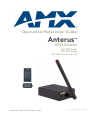
1
Operation/Reference Guide
Anterus
™
RFID Solution
ANT-RDR Reader
ANT-BDG Badge
ANT-TAG Device/Asset Tag
Control System Accessories
Last Updated: 10/22/2008
AMX Limited Warranty and Disclaimer
This Limited Warranty and Disclaimer extends only to products purchased directly from AMX or an AMX Authorized Partner which
include AMX Dealers, Distributors, VIP’s or other AMX authorized entity.
AMX warrants its products to be free of defects in material and workmanship under normal use for three (3) years from the date of
purchase, with the following exceptions:
•
Electroluminescent and LCD Control Panels are warranted for three (3) years, except for the display and touch overlay components are warranted for a period of one (1) year.
•
Disk drive mechanisms, pan/tilt heads, power supplies, and MX Series products are warranted for a period of one (1) year.
•
AMX lighting products are guaranteed to switch on and off any load that is properly connected to our lighting products, as long
as the AMX lighting products are under warranty. AMX also guarantees the control of dimmable loads that are properly connected to our lighting products. The dimming performance or quality there of is not guaranteed, impart due to the random combinations of dimmers, lamps and ballasts or transformers.
•
AMX software is warranted for a period of ninety (90) days.
•
Batteries and incandescent lamps are not covered under the warranty.
•
AMX AutoPatch Epica, Modula, Modula Series4, Modula CatPro Series and 8Y-3000 product models will be free of defects in
materials and manufacture at the time of sale and will remain in good working order for a period of three (3) years following the
date of the original sales invoice from AMX. The three-year warranty period will be extended to the life of the product (Limited
Lifetime Warranty) if the warranty card is filled out by the dealer and/or end user and returned to AMX so that AMX receives it
within thirty (30) days of the installation of equipment but no later than six (6) months from original AMX sales invoice date. The
life of the product extends until five (5) years after AMX ceases manufacturing the product model. The Limited Lifetime Warranty
applies to products in their original installation only. If a product is moved to a different installation, the Limited Lifetime Warranty
will no longer apply, and the product warranty will instead be the three (3) year Limited Warranty.
All products returned to AMX require a Return Material Authorization (RMA) number. The RMA number is obtained from the AMX
RMA Department. The RMA number must be clearly marked on the outside of each box. The RMA is valid for a 30-day period. After
the 30-day period the RMA will be cancelled. Any shipments received not consistent with the RMA, or after the RMA is cancelled, will
be refused. AMX is not responsible for products returned without a valid RMA number.
AMX is not liable for any damages caused by its products or for the failure of its products to perform. This includes any lost profits, lost
savings, incidental damages, or consequential damages. AMX is not liable for any claim made by a third party or by an AMX Authorized Partner for a third party.
This Limited Warranty does not apply to (a) any AMX product that has been modified, altered or repaired by an unauthorized agent or
improperly transported, stored, installed, used, or maintained; (b) damage caused by acts of nature, including flood, erosion, or earthquake; (c) damage caused by a sustained low or high voltage situation or by a low or high voltage disturbance, including brownouts,
sags, spikes, or power outages; or (d) damage caused by war, vandalism, theft, depletion, or obsolescence.
This limitation of liability applies whether damages are sought, or a claim is made, under this warranty or as a tort claim (including
negligence and strict product liability), a contract claim, or any other claim. This limitation of liability cannot be waived or amended by
any person. This limitation of liability will be effective even if AMX or an authorized representative of AMX has been advised of the
possibility of any such damages. This limitation of liability, however, will not apply to claims for personal injury.
Some states do not allow a limitation of how long an implied warranty last. Some states do not allow the limitation or exclusion of incidental or consequential damages for consumer products. In such states, the limitation or exclusion of the Limited Warranty may not
apply. This Limited Warranty gives the owner specific legal rights. The owner may also have other rights that vary from state to state.
The owner is advised to consult applicable state laws for full determination of rights.
EXCEPT AS EXPRESSLY SET FORTH IN THIS WARRANTY, AMX MAKES NO OTHER WARRANTIES, EXPRESSED OR
IMPLIED, INCLUDING ANY IMPLIED WARRANTIES OF MERCHANTABILITY OR FITNESS FOR A PARTICULAR PURPOSE. AMX
EXPRESSLY DISCLAIMS ALL WARRANTIES NOT STATED IN THIS LIMITED WARRANTY. ANY IMPLIED WARRANTIES THAT
MAY BE IMPOSED BY LAW ARE LIMITED TO THE TERMS OF THIS LIMITED WARRANTY. EXCEPT AS OTHERWISE LIMITED
BY APPLICABLE LAW, AMX RESERVES THE RIGHT TO MODIFY OR DISCONTINUE DESIGNS, SPECIFICATIONS, WARRANTIES, PRICES, AND POLICIES WITHOUT NOTICE.
Table of Contents
Table of Contents
Anterus™ RFID Solution .....................................................................................1
Overview .................................................................................................................. 1
ANT-RDR RFID Reader.............................................................................................. 2
ANT-RDR Product Specifications..................................................................................... 3
ANT-RDR Mounting/Installation ...................................................................................... 3
Anterus RFID Tags .................................................................................................... 4
RFID Tags - Internal Battery ............................................................................................ 4
ANT-TAG Device/Asset Tag...................................................................................... 5
ANT-TAG Product Specifications .................................................................................... 5
ANT-TAG Mounting/Installation ...................................................................................... 6
ANT-TAG Antenna Orientation ....................................................................................... 6
ANT-BDG ID Badge Tag ........................................................................................... 6
ANT-BDG Product Specifications .................................................................................... 7
ANT-BDG Mounting/Installation ..................................................................................... 7
ANT-BDG Antenna Orientation ....................................................................................... 7
Signal Strength Behavior of AMX RFID Tags and Readers ....................................... 8
Environmental Factors .............................................................................................. 8
Non-Ideal Antenna Gain .................................................................................................. 8
Antenna Elevation ........................................................................................................... 8
People and Objects......................................................................................................... 9
Multipath Fading............................................................................................................. 9
Analysis..................................................................................................................... 9
Measured Data................................................................................................................ 9
Conclusions ................................................................................................................... 10
Installation ........................................................................................................11
Overview ................................................................................................................ 11
Connecting the ANT-RDR To a NetLinx Master ...................................................... 11
Connecting Additional ANT-RDRs........................................................................... 11
Wiring Guidelines.......................................................................................................... 12
Cable Types and Maximum Distances..................................................................... 12
Pre-manufactured AXlink cable ..................................................................................... 12
Power Distribution ........................................................................................................ 12
Calculating AXlink wiring distances............................................................................... 12
Assigning the ANT-RDR Device Address ................................................................ 13
Anterus RFID Solution
i
Table of Contents
Anterus Configuration Manager .......................................................................15
Overview ................................................................................................................ 15
Accessing the RFID Configuration Manager ........................................................... 15
RFID Configuration Manager (Main page) .............................................................. 17
Global Register Page .............................................................................................. 19
Global Reader Configuration Options ........................................................................... 20
Adding a Tag to the System.......................................................................................... 21
Removing a Tag from the System.................................................................................. 21
Anterus Tags Configuration Options ............................................................................. 22
Viewing Tag Details....................................................................................................... 23
Reader Configuration Pages ................................................................................... 24
Reader Configuration Options ...................................................................................... 25
Programming ....................................................................................................27
Anterus Duet Module - Overview ........................................................................... 27
Implementing the Anterus Duet Module....................................................................... 27
Port Mapping ................................................................................................................ 28
Channels........................................................................................................................ 28
NetLinx Send Commands .............................................................................................. 28
AxLink Programming Overview .............................................................................. 28
Send Commands ........................................................................................................... 28
AXLink Channels............................................................................................................ 30
AXLink Levels ................................................................................................................ 31
ii
Anterus RFID Solution
Anterus™ RFID Solution
Anterus™ RFID Solution
Overview
The Anterus™ RFID Solution provides a Radio Frequency IDentification (RFID) solution from AMX
that extends the capabilities of the integrated A/V or control system. Anterus provides the ability to
monitor devices for asset control, as well as to define control system functionality based on the presence
of an RF Tag.
ANT-RDR Readers interface to the NetLinx Master via the AXLink bus. Anterus Tags actively send RF
messages communicating their information to ANT-RDR Readers at a distance. By design, the Tags are
active at all times. The ANT-RDR filters RF messages to ensure only messages from RF Tags in the
AMX system are forward to the control system.
Each ANT-RDR Reader detects Anterus RF Tags within its monitored zone of up to 100 feet
(30 m).
Anterus products are designed to not interfere with WiFI and Zigbee frequency spectrum used
by other AMX products
The Anterus RFID Solution is intended for asset tracking and system control. It is not
to be used as a primary asset or personnel security system.
Anterus components include:
ANT-RDR Reader (FG5172): The ANT-RDR connects to the NetLinx controller to initiate
system events when an Anterus RF asset tag or ID badge passes into its zone. See the ANTRDR RFID Reader section on page 2 for product details.
ANT-TAG Device/Asset Tag (FG5172-01): The ANT-TAG device/asset tag attaches to
devices to identify and track their location and trigger system events. See the ANT-TAG
Device/Asset Tag section on page 5 for product details.
ANT-BDG Badge Tag (FG5172-03): The ANT-BDG badge tag is worn by personnel to
identify them, track their location within a facility, and trigger system events while in
proximity to an Anterus reader. See the ANT-BDG ID Badge Tag section on page 6 for
product details.
Anterus Duet Module: The Anterus Duet Module interfaces ANT-RDR Readers with
NetLinx controllers. See the Programming section on page 27 for details.
Anterus RFID Solution
1
Anterus™ RFID Solution
ANT-TAG
Device/set Tag
ANT-BDG
Badge Tag
ANT-RDR
RFID Reader
FIG. 1 Anterus RFID Group
ANT-RDR RFID Reader
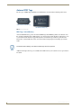
The ANT-RDR (FG5172) connects to the NetLinx controller to initiate system events whenever an ANTTAG Device/Asset tag, or ANT-BDG ID badge passes into its zone (FIG. 2).
RF Stub Antenna (433 MHz)
8-position
DEVICE
DIP Switch
4-pin AxLink
Connector
AxLink/RF
Status LEDs
Front
Rear
FIG. 2 ANT-RDR RFID Reader
The ANT-RDR communicates with the NetLinx Master via AXLink, which supports up to
255 devices on a single AXLink bus spanning for a total distance of 3000 feet (915 m).
The ANT-RDR uses a 4-pin 3.5 mm mini-Phoenix (male) connector to provide data and power
to the ANT-RDR via the AXLink bus.
2
Anterus RFID Solution
Anterus™ RFID Solution
AXLink supports multiple topologies including Star, Daisy-Chain, or a combination of
both Star and Daisy-Chain.
ANT-RDR Product Specifications
The following table provides product specifications for the ANT-RDR Reader:
ANT-RDR Specifications
Front Panel Components:
• RF Status LED (red): Indicates reception from RFID tag.
• AXLINK Status LED (green): Blinks to indicate the device is installed and
communicating properly.
Solid ON = Power on, but no master connection.
Solid OFF = No power
• RF Stub Antenna (433.92 MHz)
Rear Panel Components:
• AxLink connector - 4-pin 3.5 mm mini-Phoenix (male) connector provides data
and power to the ANT-RDR.
• DEVICE ID 8-position DIP Switch - Used to set the unique binary device
number. The device number is set by the total value of DIP switch positions
that are ON (down).
RF Specifications:
• Transmission Frequency: 433.92 MHz
• Transmission Range: Up to 100 feet/30 meters (adjustable)
Note: Tag and Reader communication distances assume optimal orientation
between Tag and Reader. Read distances may also vary as a result of the presence of metal and environmental conditions.
System Limitations:
• Up to 30 ANT-RDRs per system
• Up to 250 tags (ANT-TAG or ANT-BDG) per ANT-RDR
Power Requirements:
• 780 mW; ±12 VDC, 90 mA (max.)
• Power provided by 4-pin AxLink connector.
Environmental:
• Operational temperature: 32º F to 140º F (0º C to 60º C)
• Storage temperature: -4º F to 158º F (-20º C to 70º C)
• Humidity: 5% to 90% (non condensing)
Enclosure:
Dimensions (HWD):
Black Metal Powder coat
• .906 x 2.500 x 3.424 (23.01 mm x 63.50 mm x 86.96 mm)
• Does not include antenna.
Weight:
4 oz. (113.4 grams)
Certification:
The following standards applied in accordance with Article 5 of the directive,
1999/5/EC:
• EN 300 220-1 V1.2.1 (1997-11)
• ETS 300 683 (1997-03)
Other AMX Equipment:
• AC-DIN-EXTR DIN Rail Mounting Bracket (FG532-05)
Anterus products are designed to not interfere with WiFI and Zigbee frequency
spectrum used by other AMX products.
ANT-RDR Mounting/Installation
The ANT-RDR can be DIN-Rail mounted using the (optional) AC-DIN-EXTR DIN Rail Mounting
Bracket (FG532-05). Refer to the documentation included with the AC-DIN-EXTR DIN for mounting
instructions.
Anterus RFID Solution
3
Anterus™ RFID Solution
Anterus RFID Tags
The two types of RFID Tags (ANT-TAG, and ANT-BDG) are described in the following subsections:
ANT-TAG Device/Asset Tag
ANT-BDG ID Badge Tag
FIG. 3 Anterus RFID Tags
RFID Tags - Internal Battery
An internal lithium battery powers the Anterus RFID Tags. Each RFID Tag will, for the duration of its
life, transmit a Radio Frequency (RF) signal at a pre-set time interval. The Tag life is estimated at 5 years
at a transmission time interval of approximately 10 seconds. The life span of the Tag ends when the
battery life is exhausted. Battery status can be inferred by interrogating the internal Tag Age Counter
Value.
The internal lithium battery in the Anterus RFID Tags cannot be replaced.
Additional and replacement tags are available from AMX. Contact your customer service representative
for details.
4
Anterus RFID Solution
Anterus™ RFID Solution
ANT-TAG Device/Asset Tag
The ANT-TAG Device/Asset Tag (FG5172-01) attaches to devices to identify and track location, and
trigger system events (FIG. 4). .
FIG. 4 ANT-TAG Device/Asset Tag
Attach the ANT-TAG to a stationary or mobile asset to monitor the location of the asset. A tagged asset
may be a non-controllable object not traditionally connected to a Master Control System, or a mobile
device that is regularly moved throughout a facility.
ANT-TAG Product Specifications
ANT-TAG Specifications
RF Specifications:
• Tx Frequency: 433 Mhz
• Field strength: < 1600 µV/m
• Modulation: ASK
• Stability: Saw Stabilized
• External Antenna
Electrical Specifications:
• Power: Internally powered Lithium Battery (non-replaceable)
• Battery Life span: approximately 5 years.
Note: All of the Anterus RFID tags run on non-replaceable batteries, which
provide approximately five years of normal use. Additional and replacement tags
are available from AMX. Contact your customer service representative for
details.
Environmental:
• Operational temperature: 32º F to 140º F (0º C to 60º C)
• Storage temperature: -4º F to 158º F (-20º C to 70º C)
• Humidity: 5% to 90% (non condensing)
Enclosure:
• ABS (ultrasonically sealed) IP 65
• Charcoal Grey
Dimensions (HWD):
2.52" x 1.18" x .35" (64 mm x 30 mm x 9 mm)
Weight:
0.8 oz. (22.68 grams)
Certifications:
This device complies with Part 15 of the FCC Rules. Operation is subject to the
following two conditions:
• This device may not cause harmful interference, and,
• This device must accept any interference received, including interference that
may cause undesired operation.
The following standards applied in accordance with Article 5 of the directive,
1999/5/EC:
• EN 300 220-1 V1.2.1 (1997-11)
• ETS 300 683 (1997-03)
Any modification of this device without the express consent of the manufacturer
could void the user authority to operate the equipment.
Anterus RFID Solution
5
Anterus™ RFID Solution
ANT-TAG Mounting/Installation
ANT-TAG Tags can be mounted on a variety of non-metallic items. Where permanent fixing is required,
VHB double-sided tape is used (L-TA400).
ANT-TAG Antenna Orientation
For optimal RF reception, the tags should be mounted in the same orientation as the antenna used on the
reader. The system will still function if the orientations do no match however, the range will be
decreased. It is best to mount all tags in the same orientation no matter if it matches the orientation of the
antenna. The tag’s vertical orientation is with the antenna of the tag facing up or down. The tag’s
horizontal orientation is with the antenna to the either side. FIG. 5 provides an Orientation Diagram for
the ANT-RDR, and ANT-TAG:
Vertical Orientation
ANT-RDR
ANT-TAG
Horizontal Orientation
ANT-RDR
ANT-TAG
FIG. 5 ANT-RDR / ANT-TAG Antenna Orientation
ANT-BDG ID Badge Tag
The ANT-BDG badge tag (FG5172-02) is worn by personnel to identify them, track their location within
a facility and trigger system events while in proximity to an ANT-RDR RFID Reader (FIG. 6).
FIG. 6 ANT-BDG ID Badge Tag
6
Anterus RFID Solution
Anterus™ RFID Solution
ANT-BDG Product Specifications
ANT-BDG Specifications
RF Specifications:
• Tx Frequency: 433 Mhz
• Field strength: < 1600 µV/m
• Modulation: ASK
• Stability: Saw Stabilized
Electrical Specifications: • Power: Internally powered Lithium Battery (non-replaceable)
• Battery Life span: approximately 5 years.
Note: All of the Anterus RFID tags run on non-replaceable batteries, which
provide approximately five years of normal use. Additional and replacement tags
are available from AMX. Contact your customer service representative for details.
Environmental:
• Operational temperature: 32º F to 140º F (0º C to 60º C)
• Storage temperature: -4º F to 158º F (-20º C to 70º C)
• Humidity: 5% to 90% (non condensing)
Enclosure:
• ABS (ultrasonically sealed) IP 65
• Black
Dimensions (HWD):
3.38" x 2.12" x .19" (86 mm x 54 mm x 5mm)
Weight:
0.8 oz. (22.68 grams)
Certifications:
This device complies with Part 15 of the FCC Rules. Operation is subject to the
following two conditions:
• This device may not cause harmful interference, and,
• This device must accept any interference received, including interference that
may cause undesired operation.
The following standards applied in accordance with Article 5 of the directive, 1999/
5/EC:
• EN 300 220-1 V1.2.1 (1997-11)
• ETS 300 683 (1997-03)
Any modification of this device without the express consent of the manufacturer
could void the user authority to operate the equipment.
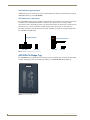
ANT-BDG Mounting/Installation
ANT-BDG Tags can be mounted on a variety of items. Where permanent fixing is required VHB doublesided tape is used (Product number L-TA200); otherwise, the tags may be worn on a necklace or clipped
to clothing.
If you will be fixing personnel photos to the ANT-BDG, use a Badge/Slot Punch capable of a throat
reach of 1/4” (FIG. 7).
Depth =.25” (6.35mm)
Punch-out height =
.25” (6.35mm)
Punch-out width = 1.625” (41.27mm)
FIG. 7 ANT-BDG - Slot Punch dimensions
ANT-BDG Antenna Orientation
ANT-BDG ID Badge tags are typically worn on a necklace or clipped to clothing, which typically results
in a vertical antenna orientation. There is a horizontal orientation for the ANT-BDG Tags, but it is
typically reserved for installations that use the ANT-BDG Tags as windshield-mounted vehicle tags.
Anterus RFID Solution
7
Anterus™ RFID Solution
Signal Strength Behavior of AMX RFID Tags and Readers
The AMX RFID system tracks assets and personnel by measuring the strength of the RF signal received
from a periodically transmitting badge or tag. Every reader within communication range measures the
signal strength and reports it to the master controller. Most often the asset or person will be located
closest to the reader reporting the strongest strength. There are, however, several environmental factors
that impact the strength of the received signal. The following subsections describe these factors, present
measured data, and describe the overall behavior to be expected from a system based on measurement of
signal strength of a transmitted UHF radio signal.
Environmental Factors
Several environmental phenomena have potential for changing the actual received level. They are each
discussed in the following sections. These effects are important to understand and keep in mind, as their
net effect will typically be to make the tag appear to be farther away than it actually is. Also be aware,
these factors can and do occur simultaneously and are additive in their effects.
Non-Ideal Antenna Gain
The ideal antenna would be one that transmits or receives with equal efficiency in all directions. In the
real world such an antenna, with a perfectly spherical gain pattern, does not exist. Commonly used
antenna types generally fall miserably short, with blind spot nulls in one or more directions. Both the
badge and asset tags employ a technique referred to as diversity antennas to achieve an omnidirectional
pattern that is much closer to the ideal, but still not quite the ideal perfect sphere. The reader antenna,
when oriented vertically, has a doughnut-shaped pattern, receiving equally well in all directions in a
horizontal plane. It has substantial blind spots when trying to receive from above or below, so it is
important to keep the reader antenna vertical if all tags to be read are on the same floor of a facility.
Antenna Elevation
RF signal strength loss is affected by the elevation of both the transmitting and receiving antennas above
ground. In general, if either or both ends are close to the floor the received signal will be weaker. This is
especially pronounced at greater distances. FIG. 8 illustrates this phenomenon. Thus, if maximum range
is required by a specific application the readers should be mounted at least a couple meters above the
ground.
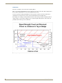
FIG. 8 Antenna Height Influence on Received Signal Strength
8
Anterus RFID Solution
Anterus™ RFID Solution
People and Objects
When radio signals pass through materials other than air their strength is typically reduced more than
passing through the same distance in air. The amount of additional decrease depends on the type of
material. The loss through most dry non-metallic materials is only moderate. Loss through many liquids
is greater. It is because the human body is composed mostly of water that radio signals will be reduced if
a person is wearing an RFID badge and facing away from the reader. Radio signals cannot pass through
solid metal objects and surfaces at all but generally, through reflections, can find their way around them.
Contact between a badge or tag and a person or object will also have some effect on the signal strength
radiated outward, in the direction away from the person or object. This occurs when the signal reflected
from the body or object adds to or subtracts from the one radiated directly outward.
Multipath Fading
This is an environmental phenomenon you've probably experienced while driving your car and listening
to the radio. You pull up to a stop sign and your station suddenly gets weak or disappears. You pull
forward as little as a few inches and the station immediately comes back strong and clear. You just
experienced a multipath fade. Because of reflections, radio signals can take many paths to get from the
transmitting antenna to the receiving antenna. When two or more copies of the signal from different
paths arrive at the receiving antenna they can either add to each other or cancel each other. The addition
is quite limited in how much the signal can be boosted but the cancellation can, in the worst case, make
the signal completely disappear. Fortunately this complete cancellation rarely happens and is likely to be
brief in duration. The use of diversity antennas in badges and asset tags provide some mitigation of this
phenomenon but cannot completely eliminate it. If diversity antennas were not used, it would be a
common occurrence for the signal strength to be near zero in as short a range as 10 feet.
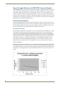
Analysis
Given the transmitted power and antenna characteristics, it is a straightforward mathematical calculation
to predict what the received signal strength can be when no environmental effects are present. This
calculation is plotted in the graph shown on the next page as the heavy black line. In general, this
estimates the best case signal strength, as environmental effects have much higher potential for reducing
the received signal strength than increasing it. The antenna heights are assumed to be 2 meters on both
ends.
Measured Data
Signal strength data was recorded from a population of 4 readers and 19 badges and asset tags at 10, 50,
100, and 200 feet. Data was taken with the badges and tags in several different orientations to take into
account the variations in badge and tag antenna radiation patterns.
The data is represented in FIG. 9 (next page) as blue vertical bars showing the total range of the recorded
data.
Anterus RFID Solution
9
Anterus™ RFID Solution
Conclusions
Two basic conclusions can be made from examining FIG. 9:
First, a very strong signal implies the person or object is very close to the reader. This is simply due to
the fact that it is impossible to receive a strong signal from far away.
Second, a tag with a weak signal is likely to be far away, but can also be near due to reductions in
strength that can come from one or more of the environmental factors described above.
For example, for a reading of 150, the distance between reader and tag is almost certainly less than or
equal to 20 feet. A tag at 20 feet is likely to have a signal strength reading between 150 and 70, and
possibly weaker if the tag's view is obstructed.
FIG. 9 Signal Strength Count Behavior
10
Anterus RFID Solution
Installation
Installation
Overview
Installation and configuration of the Anterus solution includes connecting the ANT-RDR Reader to the
NetLinx Master via AxLink, and using the ANT-RDR’s built-in web interface to name each RFID tag,
and specify communications and security settings.
NetLinx Master
ANT-RDR
Anterus Tags
FIG. 10 Basic Anterus System
Connecting the ANT-RDR To a NetLinx Master
PWR
AXP
AXM
GND
PWR
AXP
AXM
GND
The ANT-RDR uses a single 4-pin captive-wire AxLink port to connect the ANT-RDR to a NetLinx
Master, and (optionally) to other ANT-RDRs. To connect the ANT-RDR to the NetLinx Master via
AxLink, install the AXlink data/power bus wiring as shown in FIG. 11.
NetLinx Master
ANT-RDR
FIG. 11 AXlink data/power connections
Connecting Additional ANT-RDRs
NetLinx Master
ANT-RDR
ANT-RDR
ANT-RDR
PWR
AXM
AXP
GND
PWR
AXM
AXP
GND
PWR
AXP
AXM
GND
PWR
AXM
AXP
GND
PWR
AXP
AXM
GND
To connect additional ANT-RDRs to create a RFID Reader Network Group, follow the standard AxLink
bus wiring (FIG. 12).
ANT-RDR
FIG. 12 Connecting Additional ANT-RDRs
Anterus RFID Solution
11
Installation
Wiring Guidelines
The interface requires a 12 VDC power to operate properly. The interface uses a PSN2.8 power supply.
The Central Controller supplies power via the AXlink cable or external 12 VDC power supply. The
maximum wiring distance between the Central Controller and interface is determined by power
consumption, supplied voltage, and the wire gauge used for the cable.
Cable Types and Maximum Distances
Compatible AXlink cable types include those manufactured by Liberty Wire & Cable Inc., and cables
that comply with Category 5 or Belden 8102 standards. To determine the maximum distances, refer
toPower Distribution section on page 12.
Pre-manufactured AXlink cable
The Liberty Wire & Cable Inc. manufactures AXlink cable that contains two pairs of conductors. The
data pairs comprise 22 AWG stranded shielded twisted pair (STP) with a single drain wire, and a 12
VDC power pair of 18 AWG stranded wire. The nominal capacitance between the data conductors is
12.5 pF/ft.
Using the Liberty Wire & Cable Inc. AXlink cable, the maximum overall cable distance between the
Central Controller and all external devices for data communication is 3,000 feet with no remote power.
You can contact Liberty Wire & Cable Inc. at 4630 Forge Road, Suite A, Colorado Springs, CO
80907 or by calling (800) 530-8998.
Power Distribution
The following table lists the maximum cable lengths by electrical current and wire gauges (AWG). These
distances are based on a min. of 13.5 volts available at the Central Controller's power supply.
Maximum AXlink current and cable lengths by wire AWG
Maximum Current
Cable length by wire AWG
Milliampere (mA)
18 AWG
20 AWG
22 AWG
24 AWG
50
2,347
1,485
926
584
100
1,174
743
463
292
250
469
297
185
117
500
235
149
93
58
1,000
117
74
46
29
Calculating AXlink wiring distances
All AXlink devices require a minimum of 12 VDC power to operate properly. The power can be supplied
by the Central Controller's AXlink cable (remote power configuration) or with an optional 12 VDC
power supply (local power configuration). The maximum wiring distance between the power supply and
AXlink device is determined by power consumption, supplied voltage, and the wire gauge used for the
cable. Use the three-step formula below to calculate the maximum wiring lengths allowable between the
Central Controller and external AXlink devices.
Most power supplies are factory set to 13.5 VDC. Never use a power supply that exceeds 18 VDC
for remote or local power configurations. Contact AMX for a complete list of products and their
power consumption ratings.
12
Anterus RFID Solution
Installation
To calculate the AXlink wiring distance formula for data and power:
1. <Total current consumption of all device's on AXlink cable> *<wire resistance per foot> *
2 = <voltage drop per foot>. See tables below for the Wire Resistance/Foot values.
2. <Power supply voltage> - 12 VDC = <surplus voltage dissipation for cable run>.
3. <Surplus voltage dissipation for cable run> / < voltage drop per foot > =
Maximum distance in feet.
The following table lists the resistance factors used in the formula.
Gauge/resistance factors - Solid Copper Wiring
Wire gauge
Wire Resistance/foot
18 AWG
.00639
20 AWG
.0101
22 AWG
.0162
24 AWG
.0257
For further details on AxLink Wiring, refer to the AXlink Wiring Considerations
Instruction Manual (available online at www.amx.com).
Assigning the ANT-RDR Device Address
The ANT-RDR sets its AXLink address via the 8-position DEVICE DIP switch located on the rear panel
(FIG. 13).
FIG. 13 Device DIP Switch
The AXLink address distinguishes a device on the AXLink bus from other devices. Care
should be taken by the system integrator not to assign duplicate AXLink addresses to multiple
devices.
AXLink addresses must be in the range of 1 to 255 (address 0 belongs to the Master).
As indicated on the device, flip each switch down for the ON position.
Device DIP Switch Settings
Position
1
2
3
4
5
6
7
8
Value
1
2
4
8
16
32
64
128
For example, the DIP switch shown in FIG. 13 defines Device 96 (switches 6 and 7 = ON).
The device number takes effect only upon power-up. If you later change the device
number, remove and reconnect the AXlink connector to enter the new device number
into memory.
Anterus RFID Solution
13
Installation
14
Anterus RFID Solution
Anterus Configuration Manager
Anterus Configuration Manager
Overview
The Anterus Duet Module interfaces ANT-RDR Readers with NetLinx controllers, and adds the Anterus
Configuration Manager to the NetLinx Master’s built-in web console. The Anterus Configuration
Manager allows you to configure the Reader and all Tags in the Anterus solution via a web browser on
any PC that has access to the NetLinx Master to which the ANT-RDR is connected.
A sample UI module and a touch panel file are provided in the module package. These are not intended
to cover every possible application, but can be expanded as needed to meet the requirements of a
particular installation. Refer to the documentation supplied with the Anterus Duet Module for more
details.
The Anterus solution will also work without the Duet module, and all web
configuration may be done with Send Commands, Channels and Levels. Refer to the
Programming section on page 27 for detailed programming information.
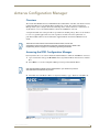
Accessing the RFID Configuration Manager
From any PC that has access to the LAN that the NetLinx Master to which the ANT-RDR is connected:
1. Open a web browser and type the IP Address of the target NetLinx Master in the browser’s Address
Bar.
2. Press Enter to access the Configuration Manager for the specified NetLinx Master.
If the specified NetLinx Master requires authentication, you will have to provide a
valid Username and Password to proceed.
3. The initial view is the Master’s Master Configuration Manager page - WebControl tab (FIG. 14).
FIG. 14 Master Configuration Manager page - WebControl tab
Anterus RFID Solution
15
Anterus Configuration Manager
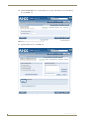
4. Click the System button to access the Manage System page. The initial view is of the Manage
System tab (FIG. 15).
FIG. 15 Manage System page - Manage System tab
5. Open the Manage Devices tab (FIG. 16).
FIG. 16 Manage System page - Manage Devices tab
16
Anterus RFID Solution
Anterus Configuration Manager
6. Under Device Configuration Pages, click on RFID, then select AMX Anterus (FIG. 17).
FIG. 17 Manage Devices tab - Device Configuration Pages options
This opens the RFID Configuration Manager (Main page).
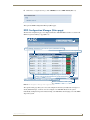
RFID Configuration Manager (Main page)
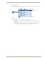
The first web configuration page to be displayed when the ANT-RDR Web Console is accessed is the
RFID Configuration Manager page (FIG. 18).
Click to refresh the webconsole
"Global Settings" indicates the entire Anterus System (ANT-RDRs and Tags)
Click to access the Global Register page
Click to access the Reader Configuration page for each ANT-RDR.
Settings made to individual Readers will override Global settings.
Listing of all ANT-RDRs currently connected to this NetLinx Master.
Click to re-initialize the RFID System
FIG. 18 RFID Configuration Manager - Main Page (initial view)
The options in this page allow you to view and configure the Anterus system (Readers and tags) as a
whole (Global Settings), as well as view and configure each ANT-RDR Reader in the system
individually. Configuration options include naming each ANT-RDR, and managing each of the RFID
Tags in the system.
Anterus RFID Solution
17
Anterus Configuration Manager
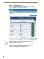
This page provides basic information on the entire Anterus System (in the Global Settings row), as well
as for each ANT-RDR connected to the NetLinx Master:
RFID Configuration Manager
• Name
Displays the Name assigned to each ANT-RDR. Reader Names can be changed, via the
Reader Configuration page - see the Reader Configuration Pages section on page 24.
Note: The "Global Settings" name cannot be changed.
• Address
Displays the device address assigned to each ANT-RDR. Reader Addresses can be
changed, via the Reader Configuration page - see the Reader Configuration
Pages section on page 24.
Note: The "Global Settings" address of zero (0) cannot be changed.
• AxLink Address Displays the AxLink device address assigned to each ANT-RDR, as it was specified on
each ANT-RDR via the 8-position DIP Switch on the rear panel (see the Assigning the
ANT-RDR Device Address section on page 13).
Note: AxLink Device Address does not apply to "Global Settings" (n/a).
• Model
Displays the Model name assigned to each ANT-RDR (read-only).
• Errors
This column indicates any errors detected by the NetLinx Master, for each ANT-RDR.
These errors are indicated by code numbers.
• Status
Indicates the status of each ANT-RDR (Online or Offline).
• Configure
• Click the icon in the Global Settings row to access the Global Register page. Use the
options in this page to specify global (system-wide) configuration options, as well as
add and remove RFID Tags from the system. See the Global Register Page section on
page 19 section for details.
• Click the icons in this column to access configuration options for the selected ANT-RDR.
See the Reader Configuration Pages section on page 24 section for details.
18
Anterus RFID Solution
Anterus Configuration Manager
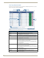
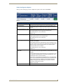
Global Register Page
Click the Configure icon in the Global Settings row (at the top of the RFID Configuration Manager page
- see FIG. 18) to access the Global Register page shown in FIG. 19:
FIG. 19 Global Register Page
The options on the Global Register page allow you to view/edit global RFID Reader settings, and add/
delete RFID Tags in the system.
Anterus RFID Solution
19
Anterus Configuration Manager
Global Reader Configuration Options
The top section of the Global Register page contains ANT-RDR configuration options (FIG. 20):
FIG. 20 Global Register page - Global Reader Configuration Options
These options apply to ALL ANT-RDR Readers in the system. Use the options in this page to
set global defaults for all Readers and Tags in the Anterus system.
Settings made to individual Readers via the Reader Configuration Pages (see the Reader
Configuration Pages section on page 24) will override these global settings.
Global Register page - Global Reader Configuration Options
• Reader ID:
Indicates the Device ID for the selected ANT-RDR. In the Global Registery
page, the Reader ID is always zero (0), and cannot be changed.
• Reader Address:
Indicates the AxLink Device Address for the selected ANT-RDR. In the
Global Registery page, the Reader ID is always "Global", and cannot be
changed.
• Acquired Threshold (1...255): The ANT-RDR will notify the Master that a Tag's signal has been acquired
when its RSSI signal is above the Acquired Threshold value.
• The allowed range is 1 (min.) to 255 (max)
• Default = 200
• Lost Threshold (0...254):
The ANT-RDR will notify the Master that a Tag's signal has been lost when
its RSSI signal is below the Lost Threshold value.
• The allowed range is 0 (min.) to 254 (max)
• Default = 50
• Sensitivity (1...255)
The Sensitivity setting is used to reduce the message traffic between the
ANT-RDR and the Master:
The ANT-RDR remembers the last RSSI value sent to the Master for each
Tag it has acquired. On the next poll, only Tags whose current RSSI value is
outside the range of the last sent RSSI value +/- the Sensitivity value
entered here will be sent to the Master.
• The allowed range is 1 (min.) to 255 (max)
• Default = 30
• Tag-Lost Timeout (30...255
seconds)
Use this option to specify the period time allowed to continue monitoring
Tags whose RFID signal has dropped below the level specified in the Lost
Threshold.
• If a Tag’s RSSI signal has dropped below the Lost Threshold level, and is
re-acquired by the Reader within the time period specified here, it will
automatically resume normal functionality.
• Conversely, if a Tag’s RSSI signal drops below the Lost Threshold level,
and is not re-acquired within the specified time period, the Reader will no
longer monitor for that Tag. Therefore, once the timeout period has
elapsed, the Tag will not be automatically re-acquired, and must be
manually re-entered into the system.
• Default = 30 seconds.
• Status (Online/Offline)
20
Indicates the current status of the selected ANT-RDR (display-only).
Anterus RFID Solution
Anterus Configuration Manager
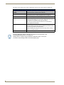
Adding a Tag to the System
1. Click the Add Tag button in the bottom-left corner of the Global Register page (FIG. 21) to add a
new RFID Tag to the system.
Click to add a new Tag
FIG. 21 Add Tag button
This invokes a set of fields for the new Tag at the bottom of the page (FIG. 22):
Tag ID
Name
Info
Acquired Threshold
FIG. 22 New tag fields
2. Enter a Tag ID.
3. Enter a Tag Name.
4. Enter Tag Info.
5. Enter the desired Acquired Threshold value for the new tag.
6. Click on the Accept button to enter the newly defined tag into the Anterus system.
Removing a Tag from the System
In either the Global Register Page or the Reader Configuration Page (see below), click on the Delete
icon for any Tag (see FIG. 23 on page 22). Once deleted, the Tag is permanently removed from the
system.
Anterus RFID Solution
21
Anterus Configuration Manager
Anterus Tags Configuration Options
The lower section of the Global Register page contains Tag configuration options. There is a separate
entry for each Tag in the Anterus system (FIG. 20):
Previous Tag
Next Tag
Previous Page
Next Page
Click to access a Tag Details
popup window for each Tag
Click to
delete a
Tag
Click to add a new Tag
FIG. 23 Tag Configuration Options (Global Register page)
Tag Configuration Options (Global Register page)
• Tag ID:
• Name:
Indicates the Tag ID assigned to each Tag (display-only).
Use this field to assign a friendly name to each Tag (optional).
Click the Accept button to save your changes.
• Detail:
Click the Detail icon to access a popup window containing detailed info (readonly) on the selected Tag (see the Viewing Tag Details section on page 23).
• Info:
Use this field to assign a descriptive string to each Tag (optional).
Click the Accept button to save your changes.
• Acquired Threshold:
The Tag’s Acquired Threshold value works in conjunction with the Reader's
Acquired Threshold setting, and can be used to further filter active RFID Tag
messages (via the Reader's Filter Tag Levels option).
Note: The Tag’s Acquired Threshold value does not override filtering already
configured on the Reader.
Click the Accept button to save your changes.
• Status (Acquired/Offline): Indicates the current status of the selected Tag (display-only).
• Acquired indicates that the Tag has been detected by the Reader and is
currently being tracked by the RFISD Reader.
• Offline indicates that the Tag has moved out of range, and is currently below
the Acquired Threshold
22
• Delete:
Click to remove any Tag from the Anterus system (see the Removing a Tag
from the System section on page 21).
• Add Tag:
Click to add a new Tag to the system (see the Adding a Tag to the
System section on page 21).
Anterus RFID Solution
Anterus Configuration Manager
Viewing Tag Details
Click on the Details icon for any Tag to invoke a popup window containing details for that Tag (FIG. 24):
Tag Name
Tag ID
Battery Level
Click to close popup
Tag Details
icon
Reader Addresses, current level at each Reader for this Tag
FIG. 24 Tag Details Popup
The Tag Details popup displays various data about the selected Tag.
The title bar of the popup window indicates the Tag Name, Tag ID, and the Tag’s current
Battery Level.
The main area of the popup lists the addresses of each Reader that is currently detecting the
selected tag, followed by the current Tag level for each Reader (for this Tag).
Anterus RFID Solution
23
Anterus Configuration Manager
Reader Configuration Pages
Click the Configure icon for any Reader in the RFID Configuration Manager page - see FIG. 18 on
page 17) to access the Reader Configuration page shown in FIG. 25:
FIG. 25 Reader Configuration Page (with "Reader 205" selected)
The Reader configuration options on this page are identical to those presented on the
Global Register page (see FIG. 19 on page 19).
The difference between the two is that the options on the Reader Configuration page
are specific to the ANT-RDR selected on the RFID Configuration Manager (Main
page).
Settings made to a specific ANT-RDR (in the Reader Configuration page - FIG. 25)
will override the Global settings made in the Global Registry page.
24
Anterus RFID Solution
Anterus Configuration Manager
Reader Configuration Options
The top section of this page provides configuration options for the selected ANT-RDR:
FIG. 26 Reader Configuration Options
Reader Configuration Page
• Reader ID:
Indicates the Device ID for the selected ANT-RDR, as specified via the
• Reader Address:
Indicates the AxLink Device Address for the selected ANT-RDR. In the
Global Registery page, the Reader ID is always "Global", and cannot be
changed.
• Acquired Threshold (1...255): The ANT-RDR will notify the Master that a Tag's signal has been acquired
when its RSSI signal is above the Acquired Threshold value.
• The allowed range is 1 (min.) to 255 (max)
• Default = 200
• Lost Threshold (0...254):
The ANT-RDR will notify the Master that a Tag's signal has been lost when
its RSSI signal is below the Lost Threshold value.
• The allowed range is 0 (min.) to 254 (max)
• Default = 50
• Sensitivity (1...255)
The Sensitivity setting is used to reduce the message traffic between the
ANT-RDR and the Master:
The ANT-RDR remembers the last RSSI value sent to the Master for each
Tag it has acquired. On the next poll, only Tags whose current RSSI value is
outside the range of the last sent RSSI value +/- the Sensitivity value
entered here will be sent to the Master.
• The allowed range is 1 (min.) to 255 (max)
• Default = 30
• Tag-Lost Timeout (30...255
seconds)
Use this option to specify the period time allowed to continue monitoring
Tags whose RFID signal has dropped below the level specified in the Lost
Threshold.
• If a Tag’s RSSI signal has dropped below the Lost Threshold level, and is
re-acquired by the Reader within the time period specified here, it will
automatically resume normal functionality.
• Conversely, if a Tag’s RSSI signal drops below the Lost Threshold level,
and is not re-acquired within the specified time period, the Reader will no
longer monitor for that Tag. Therefore, once the timeout period has
elapsed, the Tag will not be automatically re-acquired, and must be
manually re-entered into the system.
• Default = 30 seconds.
• Status (Online/Offline)
Anterus RFID Solution
Indicates the current status of the selected ANT-RDR (display-only).
25
Anterus Configuration Manager
The lower section of this page provides configuration options for each Tag assigned to this Reader:
Tag Configuration Options (Reader Configuration Page)
• Tag ID:
Indicates the Tag ID assigned to each Tag (display-only).
• Name:
Use this field to assign a friendly name to each Tag.
• Detail:
Click the Detail icon to access a popup window containing detailed info on
the selected Tag (see the Viewing Tag Details section on page 23).
• Info:
Use this field to assign a descriptive string to each Tag.
• Acquired Threshold
The Tag’s Acquired Threshold value works in conjunction with the Reader's
Acquired Threshold setting, and can be used to further filter active RFID
Tag messages (via the Reader's Filter Tag Levels option).
Note: The Tag’s Acquired Threshold value does not override filtering
already configured on the Reader.
• Status (Acquired/Offline):
Indicates the current status of the selected Tag (display-only).
• Acquired indicates that the Tag has been detected by the Reader and is
currently being tracked by the RFID Reader.
• Offline indicates that the Tag has moved out of range, and is currently
below the Acquired Threshold
• Delete
Click to remove any Tag from the ANterus system.
The Tag configuration options on this page are identical to those presented on the
Global Register page (see FIG. 19 on page 19).
Settings made to a specific Tag (in the Reader Configuration page - FIG. 25) will
override the Global settings made in the Global Registry page.
26
Anterus RFID Solution
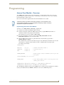
Programming
Programming
Anterus Duet Module - Overview
The COMM module translates between the standard interface described below and the device protocol. It
parses the buffer for responses from the device, sends strings to control the device, and receives commands
from the UI module or telnet sessions.
Refer to the documentation supplied with the Anterus Duet Module for more details.
A sample UI module is provided in the module package. It is not intended to cover
every possible application, but can be expanded as needed by a dealer to meet the
requirements of a particular installation.
Implementing the Anterus Duet Module
To interface to the AMX_Anterus_Comm_dr1_0_0.jar module:
1. Define the device ID for the UPS that will be controlled.
2. Define the virtual device ID that the AMX_Anterus_Comm_dr1_0_0 COMM module will use to
communicate with the main program and User Interface.
Duet virtual devices use device numbers 41000 - 42000.
3. If a touch panel interface is desired, a touch panel file AMX_Anterus.TP4 and module
AMX_Anterus_UI.axs have been created for testing.
4. The Duet AMX_Anterus_Comm_dr1_0_0 module must be included in the program with a
DEFINE_MODULE command.
This command starts execution of the module and passes in the following key information: the device ID
of the UPS to be controlled, and the virtual device ID for communicating to the main program.
An example is shown below.
DEFINE_DEVICE
dvAnterus
= 96:1:0
(* AxLink. Main RFID reader *)
vdvAnterus
= 41001:1:0
(* Virtual Device *)
dvTP
= 10001:1:0
// TP
DEFINE_VARIABLE
//Define arrays of button channels used on your own
touch panel
integer nBUTTONS[]={1,2,3,4,5,6,7}
DEFINE_START
// Place define_module calls to the very end of the
define_start section.
DEFINE_MODULE 'AMX_Anterus_Comm_dr1_0_0' Comm(vdvAnterus,dvAnterus)
DEFINE_MODULE 'AMX_Anterus_UI' UI(vdvAnterus,dvTP,nBUTTONS)
Since this API will communicate with a system of RFID readers, you must specify the AxLink device numbers
used by your install followed by a REINIT command in order to start communicating, like so:
Anterus RFID Solution
27
Programming
DEFINE_EVENT
DATA_EVENT[vdvAnterus]
{
ONLINE:
{
SEND_COMMAND vdvAnterus,'PROPERTY-Identifiers,97;98;99'
SEND_COMMAND vdvAnterus,'REINIT'
}
}
Port Mapping
This module uses a single virtual device:
Port Mapping
Virtual Device
Channels
41001:1:0 – Main All
Control
Feedback
All
All
Channels
The channels supported by the COMM module are listed below. These channels are associated with the virtual
device(s) and are independent of the channels associated with the touch panel device.
Virtual Device Channel Events
Channel
251
252
Description
ON: Device communicating (feedback only)
OFF: Device not communicating (feedback only)
ON: Data initialized (feedback only)
OFF: Data not initialized (feedback only)
NetLinx Send Commands
There are two sets of NetLinx Send Commands supported by the COMM module, one set of Control
commands and one set of Feedback commands.
Refer to the documentation supplied with the Anterus Duet Module for a full listing and description of
supported NetLinx commands, as well as Installer Tips, Naming Conventions, Programming Notes, etc.
AxLink Programming Overview
The Anterus solution will also work without the Duet module, and all web configuration may be done with
Send Commands, Channels and Levels.
Send Commands
The Anterus solution supports the AxLink Send Commands commands listed below. Note command messages
either do not have a response, or are responded to with a COMMAND - not a string.
Send Commands
RSSI Threshold
The RSSI Upper and Lower Thresholds will be sent from the Master to the
ANT-RDR in a level update message as described in the AXLink
Levels section on page 31.
• The level value is equivalent to the RSSI value with range 0 to 255.
RSSI Sensitivity Range
The RSSI Upper and Lower Thresholds will be sent from the Master to the
ANT-RDR in a level update message as described in the AXLink
Levels section on page 31.
• The level value is equivalent to the RSSI value with range 0 to 255.
28
Anterus RFID Solution
Programming
Send Commands (Cont.)
?AP
Auto Poll Time
The Tags actively transmit, and the Reader picks them up and stores them into
an event cue. "Auto poll" tells the Reader how often to read the cue.
The ANT-RDR device will enable its auto poll feature when Channel 139 is ON
and disable the auto poll feature when Channel 139 is OFF.
• Range = 50 to 6000 milliseconds (ms)
• Default = 2000 ms
Response: AP <MLSEC>
Where:
• MLSEC: mlsec in the polling interval (Range = 50 - 6000 ms).
Examples:
SEND_COMMAND '?AP
Master requests current auto poll time interval.
SEND_ COMMAND 'AP 5000
Master set, or ANT-RDR report, auto poll time interval is 5 sec.
?TG
Tag Information
The Tag Information (TG) command is sent by the Master to request the current Tag status on the ANT-RDR.
Note: This command will only report status on Tags that pass through the
Reader Filters.
The Tag message may contain information about more than one Tag bounded
by the maximum length of an AXLink message (64 bytes).
Response: TG [T<TID> R<RSSI> P<LIFE> A<AFLG> B<FUT> …]
Where:
• TID: The tag's unique Tag ID, an 8 character string formatted such that a
tag's type can be identified by the first character.
• RSSI: RSSI strength value of tag's transmission
(Range = 0 - 255, where 0 = no signal, and 255 = max RSSI signal possible).
• LIFE: The Percent of Battery Life left on the Tag (0 - 100%).
• AFLG: Activity Flag, a single byte denoting if the tag has just crossed the
Acquired Threshold and been acquired; just crossed the Lost Threshold and
is lost, or the change in RSSI value since the last sent Tag RSSI value is
greater than the Sensitivity range. Values are:
2 for acquired,
1 for RSSI value change,
0 for lost.
• FUT: Future Flag, a single byte to be populated in the future to signal an alert
when tags include tamper proof indicators or to signal a push and release
event when tags are created with a button. In this release will be set to 0.
Examples:
SEND_COMMAND '?TG
Master requests the current tag status on an ANT-RDR
SEND_ COMMAND 'TG
ANT-RDR has no tags to report
SEND_ COMMAND 'TG T12345678 R45 P25 A2 B0 T87654321 R234 P80 A1 B0
ANT-RDR reports information from 2 tags:
• TagID:12345678 RSSI:45 battery:25% has just been acquired;
• TagID:87654321 RSSI:234 battery:80% has changed RSSI value
Anterus RFID Solution
29
Programming
Send Commands (Cont.)
?ER
The Error Command (ER), command is sent by the Master to request the number of invalid tags reads encountered by the ANT-RDR.
Error Command
The ANT-RDR will respond with the number of invalid tags reads, then it will
clear the invalid read count.
Note: The ?ER command does not care why there are invalid tag reads; it just
keeps count until it gets to a certain number and then it is cleared.
• Response: ER <NUMERR>
Where:
• NUMERR: the number of invalid tags reads encountered by the ANT-RDR
since the last ?ER request.
Examples:
SEND_COMMAND '?ER
Request number of invalid tags reads
SEND_ COMMAND 'ER 5
Report 5 invalid tags reads since last ?ER request.
VER
This command is a request for the firmware version.
Request firmware version
In response, the device sends a command in the form of 'vX.XX' (e.g. v1.02) to
the Master.
AXLink Channels
Whenever communications with a Master is established, the Master assumes the ANT-RDR is at the default
channel status. Default channel status assumed by the Master is all Channels are OFF. However, the ANT-RDR
may not be in this default state and needs to inform the Master by sending an update for each channel that is
ON. After the ANT-RDR reports its Device ID to tell the Master it is online, the ANT-RDR should begin to
update the Master with any channels that are currently on.
The Guardian Channels are defined below:
AXLink Channels
Channel Type
1-138
139
140-255
Function Description
Not Used
CMD/FDBK Auto Poll
The ANT-RDR device will enable its auto poll feature when the channel
is ON and disable the auto poll feature when the channel is off.
No Used
The Type column denotes who initiates the channel change. The Master directs the
ANT-RDR to change its state through channels with type CMD. The ANT-RDR
informs the Master of state changes through channels with type FDBK. Some
channels can be used for both CMD and FDBK.
30
Anterus RFID Solution
Programming
AXLink Levels
Levels are a means of applying a value to a physical element on the device. The ANT-RDR supports 8-bit
levels only with values from 0-255 to represent RSSI values.
When a device comes ONLINE, the Master assumes the device is at the default level status with all levels set
to 0. However, the ANT-RDR may not be in this default state and needs to inform the Master the value of any
non-zero level.
After a 'LEVON' command is received from the Master the ANT-RDR sends a level update for any levels that
are non-zero.
AXLink Levels
Level Type
1
Function
CMD/FDBK RSSI Upper
Threshold
Description
The ANT-RDR will notify the Master that a tag's signal has been
acquired when its RSSI signal is above the Upper Thresholds.
• Range = 0-255, with 0 denoting the maximum range where a tag can
be acquired.
2
CMD/FDBK RSSI Lower
Threshold
The ANT-RDR will notify the Master that a tag's signal has been lost
when its RSSI signal is below the Lower Thresholds.
• Range = 0-255, with 0 denoting the maximum range where a tag can
be active before its signal is lost.
3
CMD/FDBK RSSI Sensitivity The ANT-RDR will notify the Master that a tag's signal has changed
Range
when the current RSSI value is outside the range of the last sent RSSI
value +/- the Sensitive Range.
4
Unused
Unused
Unused
5
Unused
Unused
Unused
6
Unused
Unused
Unused
7
Unused
Unused
Unused
8
Unused
Unused
Unused
• Range = 0-255, with 0 being maximum sensitivity.
The Type column denotes who initiates the level change. The Master directs the
ANT-RDR to change its state through Level of type CMD. The ANT-RDR informs the
Master of state changes through Levels of type FDBK
Anterus RFID Solution
31
Programming
32
Anterus RFID Solution
Programming
Anterus RFID Solution
33
AMX. All rights reserved. AMX and the AMX logo are registered trademarks of AMX. AMX reserves the right to alter specifications without notice at any time.
©2008
10/08
It’s Your World - Take Control™
3000 RESEARCH DRIVE, RICHARDSON, TX 75082 USA • 800.222.0193 • 469.624.8000 • 469-624-7153 fax • 800.932.6993 technical support • www.amx.com