1
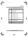
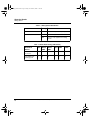
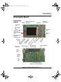
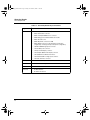
3StackQS_WinCE.book Page 1 Friday, November 21, 2008 11:46 AM
i.MX27 PDK 1.0
Windows Embedded CE 6.0
Quick Start Guide
3StackQS_WinCE.book Page 2 Friday, November 21, 2008 11:46 AM
Information in this document is provided solely to enable system and software implementers to use Freescale Semiconductor products. There are no express or implied copyright licenses granted hereunder to design or fabricate any integrated circuits or integrated circuits based on the information in this document.
Freescale Semiconductor reserves the right to make changes without further notice to any products herein. Freescale
Semiconductor makes no warranty, representation or guarantee regarding the suitability of its products for any particular purpose, nor does Freescale Semiconductor assume any liability arising out of the application or use of any product
or circuit, and specifically disclaims any and all liability, including without limitation consequential or incidental damages. “Typical” parameters that may be provided in Freescale Semiconductor data sheets and/or specifications can and
do vary in different applications and actual performance may vary over time. All operating parameters, including “Typicals”, must be validated for each customer application by customer’s technical experts. Freescale Semiconductor does
not convey any license under its patent rights nor the rights of others. Freescale Semiconductor products are not designed, intended, or authorized for use as components in systems intended for surgical implant into the body, or other
applications intended to support or sustain life, or for any other application in which the failure of the Freescale Semiconductor product could create a situation where personal injury or death may occur. Should Buyer purchase or use
Freescale Semiconductor products for any such unintended or unauthorized application, Buyer shall indemnify and hold
Freescale Semiconductor and its officers, employees, subsidiaries, affiliates, and distributors harmless against all
claims, costs, damages, and expenses, and reasonable attorney fees arising out of, directly or indirectly, any claim of
personal injury or death associated with such unintended or unauthorized use, even if such claim alleges that Freescale
Semiconductor was negligent regarding the design or manufacture of the part.
Federal Communications Commission Radio Frequency Interference Statement
This device complies with Part 15 of the FCC rules. Operation is subject to the following two conditions:
(1) This device may not cause harmful interference and
(2) this device must accept any interference received, including interference that might cause undesired operation.
Changes or modifications to this equipment not expressly approved by Freescale could void the user’s authority to operate the equipment.
Freescale™ and the Freescale logo are trademarks of Freescale Semiconductor, Inc. All other product or service names
are the property of their respective owners. Microsoft and Windows are registered trademarks of Microsoft Corporation.
RealView is a registered trademark of ARM Limited. ARM9 is the trademark of ARM Limited. The ARM logo is a
registered trademark of ARM Ltd. Wi-Fi is a registered trademark of the Wi-Fi Alliance. Bluetooth is a registered trademark of the Bluetooth SIG, Inc., and is used under license. Wi-Fi CERTIFIED is a trademark of the Wi-Fi Alliance.
© Freescale Semiconductor, Inc. 2007 - 2008. All rights reserved.
How to Reach Us:
Home Page:
www.freescale.com
E-mail:
[email protected]
USA/Europe or Locations Not Listed:
Freescale Semiconductor
Technical Information Center, CH370
1300 N. Alma School Road
Chandler, Arizona 85224
+1-800-521-6274 or +1-480-768-2130
[email protected]
Europe, Middle East, and Africa:
Freescale Halbleiter Deutschland GmbH
Technical Information Center
Schatzbogen 7
81829 Muenchen, Germany
+44 1296 380 456 (English)
+46 8 52200080 (English)
+49 89 92103 559 (German)
+33 1 69 35 48 48 (French)
[email protected]
Japan:
Freescale Semiconductor Japan Ltd.
Headquarters
ARCO Tower 15F
1-8-1, Shimo-Meguro, Meguro-ku,
Tokyo 153-0064, Japan
0120 191014 or +81 3 5437 9125
[email protected]
Asia/Pacific:
Freescale Semiconductor China Ltd.
Exchange Building 23F
No. 118 Jianguo Road
Chaoyang District
Beijing 100022
China
+86 010 5879 8000
[email protected]
For Literature Requests Only:
Freescale Semiconductor Literature Distribution
Center
P.O. Box 5405
Denver, Colorado 80217
1-800-521-6274 or 303-675-2140
Fax: 303-675-2150
[email protected]
3StackQS_WinCE.book Page 1 Friday, November 21, 2008 11:46 AM
1
About the Boards
3
About the 3-Stack Platform System . . . . . . . . . . . . . . . . . . . . . . . . . . . . . . . . . . . 3
CPU Board . . . . . . . . . . . . . . . . . . . . . . . . . . . . . . . . . . . . . . . . . . . . . . . . . . . . . . 7
Debug Board . . . . . . . . . . . . . . . . . . . . . . . . . . . . . . . . . . . . . . . . . . . . . . . . . . . . . 8
Personality Board . . . . . . . . . . . . . . . . . . . . . . . . . . . . . . . . . . . . . . . . . . . . . . . . 11
2
Getting Started
13
Unpack the Kit . . . . . . . . . . . . . . . . . . . . . . . . . . . . . . . . . . . . . . . . . . . . . . . . . . 13
CD-ROM Contents . . . . . . . . . . . . . . . . . . . . . . . . . . . . . . . . . . . . . . . . . . . . . . . 15
Provide a Development PC. . . . . . . . . . . . . . . . . . . . . . . . . . . . . . . . . . . . . . . . . 16
3
Build the Platform
17
Build a Development Platform: Assemble Three Boards. . . . . . . . . . . . . . . . . . 17
Connect Personality Board to Debug Board . . . . . . . . . . . . . . . . . . . . . . . . . 18
Connect CPU Board to Debug Board . . . . . . . . . . . . . . . . . . . . . . . . . . . . . . 19
Connect Development Platform to PC; Run Preloaded Image . . . . . . . . . . . 20
Build a Demo Platform: Assemble Two Boards. . . . . . . . . . . . . . . . . . . . . . . . . 21
Connect CPU Board to Personality Board . . . . . . . . . . . . . . . . . . . . . . . . . . 21
Connect Power Supply; Run Preloaded Demo . . . . . . . . . . . . . . . . . . . . . . 23
4
Using the Demo Image
25
Touch Pad Calibration Tool . . . . . . . . . . . . . . . . . . . . . . . . . . . . . . . . . . . . . . . . 25
Downloading Multimedia to the 3-Stack Board . . . . . . . . . . . . . . . . . . . . . . . . . 27
Using Active Sync. . . . . . . . . . . . . . . . . . . . . . . . . . . . . . . . . . . . . . . . . . . . . 27
Using an SD Card . . . . . . . . . . . . . . . . . . . . . . . . . . . . . . . . . . . . . . . . . . . . . 32
Using a USB Memory Stick . . . . . . . . . . . . . . . . . . . . . . . . . . . . . . . . . . . . . 33
Running the Demo Applications. . . . . . . . . . . . . . . . . . . . . . . . . . . . . . . . . . . . . 33
Running the TV-Out Application . . . . . . . . . . . . . . . . . . . . . . . . . . . . . . . . . 34
Changing the Windows Embedded CE 6.0 Demo Image Version . . . . . . . . 42
Ready to Begin Your Development? . . . . . . . . . . . . . . . . . . . . . . . . . . . . . . . . . 43
i.MX27 PDK 1.0 Quick Start Guide, Rev. 1.0
1
3StackQS_WinCE.book Page 2 Friday, November 21, 2008 11:46 AM
i.MX27 PDK 1.0 Quick Start Guide
2
3StackQS_WinCE.book Page 3 Friday, November 21, 2008 11:46 AM
1
About the Boards
This chapter provides detailed information about the three boards (CPU, Debug,
Personality) and the locations of the connectors and switches for each.
CAUTION
Your PDK arrives housed in a plastic device enclosure, which under
normal circumstances you should not remove. However, the PDK
documentation set includes information for board-level components, and
also explains in some documents how to assemble the boards into the
enclosure. Should you need to work directly with the boards, please use
great caution in handling the components:
– To remove or work with the boards, use static precautions.
– To remove or add the enclosure, first read the enclosure assembly instructions
carefully and note which areas are delicate, such as the speakers.
About the 3-Stack Platform System
Freescale introduces the 3-Stack Platform System, which you use to develop multimedia
and connectivity applications using the i.MX27 Applications Processor and the MC13783
Audio and Power Management device.
The 3-Stack Platform System decreases the time between first development and final
product release by providing you (as the system designer) with a near-to-final product
design, which you can use as a development platform for software and hardware.
There are two Board Support Packages (BSP) for the 3-Stack Platform System, with one
BSP for Windows Embedded CE™ 6.0, and one BSP for Linux operating systems. These
BSPs contain drivers optimized for multimedia operations using the i.MX27 and
MC13783 devices.
Freescale's 3-Stack Platform System consists of three small boards: CPU, Debug, and
Personality.
• A CPU board contains the i.MX27 CPU, memories, and the MC13783 Power
Management IC (PMIC).
• A Debug board provides the debug interfaces (such as JTAG), and also has a CPLD
that implements an external Ethernet and serial controller for debug purposes.
• The Personality board implements the functionality of the 3-Stack board, and
contains hardware for Wi-Fi connectivity, FM receiver, and so on. The Personality
board can be modified to meet your specific requirements without the need to modify
the other two boards (CPU, Debug). The Personality board was designed to support
i.MX27 PDK 1.0 Quick Start Guide, Rev. 1.0
3
3StackQS_WinCE.book Page 4 Friday, November 21, 2008 11:46 AM
About the Boards
About the 3-Stack Platform System
common multimedia applications, and has a 2.8-inch VGA display, image sensor
camera, Wi-Fi CERTIFIED™ IEEE 802.11™ b/g standards, FM receiver, SD Card
connector, USB OTG, USB Host, 2.4 QVGA smart display panel connector, ATA
connector and TV-Out connector. As the 3-Stack platform continues to evolve, more
Personality boards will be created to meet new multimedia requirements. Table 1.1
lists 3-Stack platform features in more detail.
Table 1.1 3-Stack Platform Features
Details
All boards
• Near to final product form-factor demonstration
modules and working platforms.
• Solid reference schematics that closely resemble
final products to aid customers' designs.
CPU board
• i.MX27 ARM9™ Applications Processor
• MC13783 Atlas power management chip
• 256 MB of NAND Flash Memory
• 128 MB of 32 bit DDR SDRAM memory
• 37.914 mm x 67.517 mm
Personality board
• Peripheral components
• Interface connectors
• 71.428 mm x 129.462 mm
Debug board
• Two RS-232 interfaces
• 10/100 Base-T Ethernet connector
• Current measure connectors
• 71.400 mm x 174.900 mm
Expansion Headers
• Utilizing reliable high density connector to interface
between boards, 3 board assembly for software
development and 2-board assembly (without debug
board) for demonstration
Battery Support
• +4.2 V 2400mAh Battery power supply and Battery
Charging Function
LCD Display
4
• 2.8 inch TFTLCD display panel with touch panel and
LED backlight
Smart LCD Connector
• 2.4 inch QVGA smart display panel connector
Camera Interface
• Image sensor camera connector
Selectable Clock
Sources
• Two selectable system clock sources: 32.768 KHz
and 26 Mhz
i.MX27 PDK 1.0 Quick Start Guide, Rev. 1.0
3StackQS_WinCE.book Page 5 Friday, November 21, 2008 11:46 AM
About the Boards
About the 3-Stack Platform System
Table 1.1 3-Stack Platform Features
Details
Debug Port
• RealView ®-ICE debug support
Video and Audio
Stereo
• Stereo microphone jack, headphone and video jack,
stereo and mono (ear piece) speaker terminals
GPS Connector
• One connector to outboard GPS module
FM Receiver
TV Out
• TV decoder that supports 8-bit color, NTSC and PAL
formats
PC Card Expansion
• SD card connectors, with card sense
Keypad
• Onboard keypad and keypad connector
Network Support
• Onboard Wi-Fi CERTIFIED™ IEEE 802.11 b/g
standards and Bluetooth(r) Core Specification
Version 2.0 + EDR (enhanced data rate)
combination module
• One Ethernet jack connector (for application/debug)
USB
• One USB OTG high-speed transceiver with miniUSB connector
• One USB high-speed host transceiver, with
standard USB host connector
ATA Support
ATA5 controller with
• One 44-position dual row 2 mm header for small
form-factor disk drivers
• One 40-pin ZIF connector for Toshiba HDD
Accelerometer
Serial Port
• Onboard accelerometer with sensitivity in three
separate axes (X, Y, Z)
Two RS-232 interfaces with DB-9 connectors
• One RS-232 interface is driven by a UART channel
internal to the MX27, and it supports DCE with
optional full modem controls
• The other RS-232 interface is DTE with optional full
modem controls
i.MX27 PDK 1.0 Quick Start Guide, Rev. 1.0
5
3StackQS_WinCE.book Page 6 Friday, November 21, 2008 11:46 AM
About the Boards
About the 3-Stack Platform System
Table 1.1 3-Stack Platform Features
Details
Cables
• 5.0V/2.4A universal power supply kit
• RS-232 standard serial cable
• High Speed USB cables with mini-AB connectors for
OTG
• High speed cable with standard A-to-mini-B
connectors
• Mini-USB adaptor
• Jack to RCA audio/video cable
• Ethernet cables (2) with RJ45-8 connectors
Software
• Sample Windows® embedded CE binary image
from Freescale
• Windows embedded CE BSP available from
Freescale
Application
Development Tools
• ATK software
• Platform Builder 6.0
• Visual Studio 2005
6
i.MX27 PDK 1.0 Quick Start Guide, Rev. 1.0
3StackQS_WinCE.book Page 7 Friday, November 21, 2008 11:46 AM
About the Boards
CPU Board
CPU Board
CPU
Board
Top
Bottom
J1 Board-to-Board Connector
Figure 1.1 CPU Board
You use the J1 board-to-board connector (500 pins) to connect the CPU board to either of
the other two boards:
• Connect the CPU board to a Personality board, for running demos (no Debug board
is needed).
• Connect the CPU board to a Debug board, (and connect the Personality board to the
Debug board) for developing software. The Personality board plugs into the other
side of the Debug board.
i.MX27 PDK 1.0 Quick Start Guide, Rev. 1.0
7
3StackQS_WinCE.book Page 8 Friday, November 21, 2008 11:46 AM
About the Boards
Debug Board
To Personality Board
Connector CN74
DC Power LED D11
Power-On S4
Resettable Fuse F1
3.3V LED D9
SW5–SW10 See Table 1.4
CPLD LEDs D1–
TOP
MX27 JTAG CN1
SW4 See Table 1.3
Debug
Board
Current Measure J3
Debug CPLD JTAG CN2
Debug Board
DC Power J2
Ethernet J1
P1
UART CON4
female
System Reset S3
Personality
CPLD JTAG
CN3
Power S1
Device MAC
Address
CPLD Test BT
Debug Reset S2
CPLD Test BT
P2
UART CON3
male
To CPU Board Connector
Bottom
Device
MAC
Address
Figure 1.2 Debug Board
8
i.MX27 PDK 1.0 Quick Start Guide, Rev. 1.0
3StackQS_WinCE.book Page 9 Friday, November 21, 2008 11:46 AM
About the Boards
Debug Board
Table 1.2 Debug Board Physical Features
Type
Physical Feature
Switches
• S1: Power button
• S2: Debug board reset button
• S3: System reset switch
• S4: Power-on switch
• SW4: Enable switch
Connectors
• J1:10/100 Base-T Ethernet RJ45 connector
• J2: 5.0V DC power connector
• J3: Current measure connector
• J4: 500-pin connector to CPU board
• P1: WEIM Address measure connector
• P2: WEIM Data measure connector
• CN1: i.MX27 JTAG connector
• CN2: Debug board CPLD JTAG connector
• CN3: Personality board CPLD JTAG connector (Reserved)
• CN74: 500-pin connector to Personality board
• CON4: UART (DCE) DB9 female connector
LEDs
• D1–D8: LEDs for CPLD debug
• D9: LED for Debug board 3.3V power
• D11:LED for DC power supply
Buttons
• BT1, BT2: Test buttons for CPLD
Fuse
• F1: Resettable Fuse
i.MX27 PDK 1.0 Quick Start Guide, Rev. 1.0
9
3StackQS_WinCE.book Page 10 Friday, November 21, 2008 11:46 AM
About the Boards
Debug Board
Table 1.3 Debug Board SW4 Switch
Switch
Setting
Effect
SW4-1 UART Port Select
ON
Selects serial port UART (DCE) CON4
SW4-8 Power Enable
ON
Power is supplied to all three boards.
OFF
Power is only supplied to the Debug
board.
Table 1.4 Boot Mode Setting (SW5–SW10)
10
Boot Mode
Device
SW5
Boot4
SW6
Boot3
SW7
SW8
SW9
SW10
UART/USB
bootloader
X
0
0
0
0
0
8-bit NAND Flash
(2KB page) Ext
X
0
0
0
1
0
i.MX27 PDK 1.0 Quick Start Guide, Rev. 1.0
3StackQS_WinCE.book Page 11 Friday, November 21, 2008 11:46 AM
About the Boards
Personality Board
Personality Board
Personality
Board
TOP
GiantPlus QVGA Smart
Display J15
GPS CN13
On-Board
Keypad S1–S7
Audio/Video
J19
WiFi Antenna
E1
Camera
USB OTG
J10
CMSO Sensor
CN14 (underneath
LCD)
USB Host
J18
Bluetooth
Antenna
E2
Bottom
Battery Connector
R
F u ese
se t t a
F1 ble
D
a n ebu
d g
B P
lu or
et t
oo fo
th r W
C iF
N i
ZI
16
F
fo F
rH C
D on
D ne
C c
N to
70 r
W
VG
A
K
(n
ey
ot
pa
po
d
pu
C
la
on
te
d)
ne
c
R
t
o
es
r
et
C
N
B
20
ut
to
n
Epson VGA Display
Connector
(underneath LCD)
Board-to-Board
Connector CN73
Coin Cell Battery
B1
Fast
Ethernet
J16
SD Card
Socket
CN31
DC
Power
J12
HDD Connector CN12
Figure 1.3 Personality Board
i.MX27 PDK 1.0 Quick Start Guide, Rev. 1.0
11
3StackQS_WinCE.book Page 12 Friday, November 21, 2008 11:46 AM
About the Boards
Personality Board
Table 1.5 Personality Board Physical Features
Type
Physical Feature
Connectors
• CN12: 44-position dual row, 2 mm header for HDD
• CN13: GPS module connector
• CN14: 2.0 M pixel CMOS sensor connector
• CN16: Debug port for WiFi and Bluetooth module
• CN31: SD card socket
• CN70: 40-pin ZIF connector for HDD
• CN73: 500-pin connector to CPU Engine board (in demo
configuration) or Debug board (in development configuration)
• J10: Mini-USBOTG high speed connector
• J12: 5.0 VDC power connector
• J14: Epson VGA display connector
• J15: Giantplus QVGA smart display connector
• J16: 10/100 BT Fast Ethernet Connector
• J18: Standard USB host high speed connector
• J19: Audio and video connector
Battery
• B1: Coin cell battery
Buttons
• S7–S17: Onboard keypad
Fuse
• F1: Resetable fuse
Antennas
• E1: WiFi Antenna
• E2: Bluetooth antenna
12
i.MX27 PDK 1.0 Quick Start Guide, Rev. 1.0
3StackQS_WinCE.book Page 13 Friday, November 21, 2008 11:46 AM
2
Getting Started
Unpack the Kit
The 3-Stack Platform System is shipped with the items listed in Table 2.1.
Table 2.1 Contents
Type
Items
Boards
• CPU board
• Debug board
• Personality board
Cables
• RS-232 serial cable
• Ethernet straight cable
• High-speed USB cables with mini AB
connectors for OTG
• High-speed cable with standard A to
mini B connectors
• Mini-USB adaptor
• Jack to RCA audio/video cable
Power Supply
• 5.0V/2.4A universal power supply kit
• CD-ROMs: Content CD, Platform
Builder Trail CD, and Visual Studio
2005 Trial CD
• End-User License Agreement
• Quick Start Guide (this document)
• Warranty card
• Freescale Support card
Verify that all the items are contained in the package. See .
Take out the three boards from their anti-static bags and check the boards for any visible
damage.
i.MX27 PDK 1.0 Quick Start Guide, Rev. 1.0
13
3StackQS_WinCE.book Page 14 Friday, November 21, 2008 11:46 AM
Getting Started
Unpack the Kit
CD-ROM
RS-232
Ethernet
Straight Cable
Mini-AB
USB OTG
A to Mini-B
USB Cable
A to Mini B
USB Cable
Universal
Power
Supply
CPU
Board
Debug
Board
Personality
Board
Jack to RCA
Audio/Video Cable
Figure 2.1 PDK Kit Contents
i.MX27 PDK 1.0 Quick Start Guide, Rev. 1.0
14
3StackQS_WinCE.book Page 15 Friday, November 21, 2008 11:46 AM
Getting Started
CD-ROM Contents
CD-ROM Contents
Table 2.2.identifies the items on the CD-ROM set.
Table 2.2 Development PC Requirements
Type
Requirement
Product
Documentation
• i.MX27 PDK Product Brief
• Bill of Materials, Schematics, and Gerber files for
• CPU Board, Personality Board, and Debug Board
• i.MX27 Demo Image Readme Windows Embedded
CE 6.0
• i.MX Platform Hardware User’s Guide
• i.MX27 PDK Quick Start Guides for Windows
Embedded CE 6.0 (this document)
• i.MX27 PDK Release Notes for Windows
Embedded CE 6.0
• i.MX27 PDK User’s Guides for Windows
Embedded CE 6.0
• i.MX27 PDK Reference Manuals for Windows
Embedded CE 6.0
• i.MX27 PDK Hello World Application Notes for
Windows Embedded CE 6.0
• i.MX Platform Advanced ToolKit (ATK) User’s
Guide
Software
Development Tools
• Microsoft Platform Builder, versions 6.0
• Visual Studio 2005
• Windows CE 6.0/Windows Embedded CE 6.0 SDK
installation file
• Advanced ToolKit (ATK) software
i.MX27 PDK 1.0 Quick Start Guide, Rev. 1.0
15
3StackQS_WinCE.book Page 16 Friday, November 21, 2008 11:46 AM
Getting Started
Provide a Development PC
Provide a Development PC
To develop applications using the 3-Stack development kit, get a PC with the
requirements listed in Table 2.3.
Table 2.3 Development PC Requirements
Type
Requirement
Operating System
• Windows XP Professional with Service Pack 1
or
Windows 2000 Professional with Service Pack 4
Network
• Internet access
Software Tools
• Microsoft .NET Framework, version 1.1
PC HW
• 933 MHz Pentium II or later processor;
2 GHz processor recommended
• 512 MB of RAM;
1 GB recommended
• 1 GB of available space required on system drive
• 18 GB of available hard-disk space
• DVD ROM drive
• 1024x768 or higher resolution display with 256
colors
i.MX27 PDK 1.0 Quick Start Guide, Rev. 1.0
16
3StackQS_WinCE.book Page 17 Friday, November 21, 2008 11:46 AM
3
Build the Platform
This chapter explains how to connect the three types of 3-Stack boards (Debug,
Personality, CPU) together, to make either a development platform (Personality board +
CPU board + Debug board), or a demonstration platform (Personality board + CPU
board); and how to connect the 3-Stack platform to your PC. See Figure 3.1.
Personality Board
Personality Board
Debug Board
CPU Board
CPU Board
Development
Configuration
3 Board Stack
Demo
Configuration
2 Board Stack
Figure 3.1 3-Stack Platform Configurations
The three 3-Stack boards in your development kit may already be assembled. If the three
boards are already assembled, review the procedures in the following sections, and be sure
to configure the Debug board appropriately.
• To build a development platform, follow the procedures in “Build a Development
Platform: Assemble Three Boards” on page 17.
• To build a demonstration platform, follow the procedures in “Build a Demo
Platform: Assemble Two Boards” on page 21.
Build a Development Platform: Assemble
Three Boards
This section explains how to connect the Personality, Debug, and CPU boards.
i.MX27 PDK 1.0 Quick Start Guide, Rev. 1.0
17
3StackQS_WinCE.book Page 18 Friday, November 21, 2008 11:46 AM
Build the Platform
Build a Development Platform: Assemble Three Boards
Connect Personality Board to Debug
Board
The Personality board connects to the Debug board using a 500-pin connector. The
connector is keyed to avoid misconnection, so there is only one way to connect these
boards. Connect the Personality board to the Debug board. The maximum allowable angle
for mating and unmating boards is 10 degrees. See Figure 3.2. For additional information,
see: http://samtec.com/ftppub/TESTRPT/tc076--1254reportrev3.pdf.
Personality
Board
Debug
Board
1 Align boards
Debug
Board
PersonalityBoard
2 Connect boards
Personality
Board
Debug
Board
Figure 3.2 Install Personality Board onto Debug Board
i.MX27 PDK 1.0 Quick Start Guide, Rev. 1.0
18
3StackQS_WinCE.book Page 19 Friday, November 21, 2008 11:46 AM
Build the Platform
Build a Development Platform: Assemble Three Boards
Connect CPU Board to Debug Board
After connecting the Personality board to the Debug board, now connect the CPU board to
the underside of the Debug board.
Personality Board
Debug Board
CPU
Board
1 Flip over Personality/
Debug assembly
2 Align boards
CPU Board
3 Connect CPU board to
underside of Debug
board
Personality Board
Debug Board
CPU Board
Figure 3.3 Align CPU board and Debug/Personality board
i.MX27 PDK 1.0 Quick Start Guide, Rev. 1.0
19
3StackQS_WinCE.book Page 20 Friday, November 21, 2008 11:46 AM
Build the Platform
Build a Development Platform: Assemble Three Boards
Connect Development Platform to PC; Run
Preloaded Image
2 Set Bootstrap switches
(SW5–SW10) to NAND boot
5
S4
J2
Regulated +5V
DC Supply
3
DC
power
4
Female
RS-232
cable
Configure serial
console application.
6
COM port
1
Set SW4
Figure 3.4 Connecting the Platform to your PC
To connect the 3-Stack platform to your host PC:
1. Connect one end of an RS-232 serial cable (included in the kit) to a serial port
connector (CON4) on the Debug board and connect the other end to a COM port on the
host PC.
• Configure SW4-1 to ON.
• Make sure that SW4-8 is ON, to supply power to all three boards.
• Configure SW4-2 to OFF.
2. Confirm that the Bootstrap switches (SW5–SW10) are set for NAND boot. See Table
3.1.
Table 3.1 Boot Mode Setting (SW5–SW10)
Boot Mode
Device
SW5
SW6
(Boot4)
SW7
(Boot3)
SW8
SW9
SW10
UART/USB
bootloader
X
0
0
0
0
0
8-bit NAND Flash
(2KB page) Ext
X
0
0
0
1
0
i.MX27 PDK 1.0 Quick Start Guide, Rev. 1.0
20
3StackQS_WinCE.book Page 21 Friday, November 21, 2008 11:46 AM
Build the Platform
Build a Demo Platform: Assemble Two Boards
3. Connect the regulated 5V power supply to the appropriate power adapter. Plug the
power adapter into an electrical outlet and the 5V line connector into the J2 (5V
POWER JACK) connector on the Debug board. See Figure 3-5.
4. Start a serial console application on your host PC with the following configuration
Table 3.2 Serial Console Configuration
Baud Rate
115200
Data Bits
8
Parity
None
Stop Bits
1
Flow Control
None
5. On the Debug board, switch the power switch (S4) to 1.
6. The OS image pre-loaded in the 3-Stack board will boot and the debug messages from
the bootloader should now appear on the serial console application on your PC.
Build a Demo Platform: Assemble Two
Boards
This section explains how to make a demonstration platform using the Personality and
CPU boards.
To make a demonstration platform, the CPU board is directly connected to the Personality
board using the 500-pin connector; the Debug board is not used.
NOTE
If your system is already configured as a development platform (using all three
boards), disconnect all boards from each other.
Connect CPU Board to Personality Board
Connect the CPU board to the Personality board. The connector is keyed to avoid
misconnections, so that there is only one way to connect the CPU board to the Personality
board.
i.MX27 PDK 1.0 Quick Start Guide, Rev. 1.0
21
3StackQS_WinCE.book Page 22 Friday, November 21, 2008 11:46 AM
Build the Platform
Build a Demo Platform: Assemble Two Boards
CPU Board
Personality
Board
Personality Board
1
Flip over Personality/
2 Align boards
Personality
Board
CPU Board
3 Install CPU board onto
underside of Personality
board
CPU Board
Personality/CPU
Assembly
Personality Board
Figure 3.5 Install CPU Board onto Personality Board
i.MX27 PDK 1.0 Quick Start Guide, Rev. 1.0
22
3StackQS_WinCE.book Page 23 Friday, November 21, 2008 11:46 AM
Build the Platform
Build a Demo Platform: Assemble Two Boards
Connect Power Supply; Run Preloaded
Demo
CPU/Personality Board
Regulated +5V
DC Supply
1
DC
power
J12 power jack is on the underside
of the Personality board
2
Figure 3.6 Connect Personality Board to Power Supply
1. Connect the regulated 5V power supply to the appropriate power adapter. Plug the 5V
line into the J12 (5V POWER JACK) connector on the Personality board. See Figure
3.6. Turn the 5V power supply ON.
2. The OS image pre-loaded in the 3-Stack should boot and the Windows Embedded CE
6.0 operating system should appear at the Personality board’s LCD display.
i.MX27 PDK 1.0 Quick Start Guide, Rev. 1.0
23
3StackQS_WinCE.book Page 24 Friday, November 21, 2008 11:46 AM
Build the Platform
Build a Demo Platform: Assemble Two Boards
i.MX27 PDK 1.0 Quick Start Guide, Rev. 1.0
24
3StackQS_WinCE.book Page 25 Friday, November 21, 2008 11:46 AM
4
Using the Demo Image
This chapter explains how to use the touch panel and stylus to load the multimedia content
to the 3-Stack board, using the provided demo image.
Touch Pad Calibration Tool
After you have assembled the 3-Stack board and powered it up, the Windows Embedded
CE 6.0 image that was loaded to the board will boot up. The first image you will see is the
touch pad calibration tool, which displays a cross in the center, as shown in the partial
screen image in Figure 4.1.
Figure 4.1 Touch Pad Calibration Tool
i.MX27 PDK 1.0 Quick Start Guide, Rev. 1.0
25
3StackQS_WinCE.book Page 26 Friday, November 21, 2008 11:46 AM
Using the Demo Image
Touch Pad Calibration Tool
To calibrate the Touch Panel, follow these steps:
1. Using the stylus pen, click on the cross.
The cross will move to the four corners of the screen. If the calibration error is too
large, the program will reset and the process will have to be repeated. When the touch
panel calibration is successful, the following message is displayed:
2. Tap with the stylus pen in any part of the screen.
The Windows CE desktop is displayed (see Figure 4.2.)
.
Figure 4.2 Windows CE Desktop
i.MX27 PDK 1.0 Quick Start Guide, Rev. 1.0
26
3StackQS_WinCE.book Page 27 Friday, November 21, 2008 11:46 AM
Using the Demo Image
Downloading Multimedia to the 3-Stack Board
Downloading Multimedia to the 3-Stack
Board
There are three ways to load multimedia content to the 3-Stack board using the Windows
Embedded CE 6.0 image provided:
• Using Active Sync
• Using an SD Card
• Using a USB Card
Using Active Sync
Active Sync is a very useful tool to use with a Windows Embedded CE 6.0 device. To
obtain the Active Sync download and instructions, go to:
http://www.microsoft.com/windowsmobile/activesync/activesync45.mspx/
Once Active Sync is installed, you can set up communication between your host PC and
the 3-Stack board.
To establish a communication between the Host PC and the 3-Stack board, follow these
steps:
1. Make sure that the 3-Stack board is ON and running the Windows Embedded CE 6.0
image.
2. Make sure that Active Sync is running on your host PC (the Active Sync icon should
appear gray on the Windows task bar).
3. Use the A to mini AB USB cable provided in your i.MX27 MAX WPDK kit and
connect the mini AB end to the J10 USB OTG connector on the Personality board,
then connect the other end to the any available USB port on your Host PC.
Windows will recognize the 3-Stack board as a Windows Embedded CE 6.0 Device
and the Active Sync wizard will appear on the Host PC (Figure 4.3).
i.MX27 PDK 1.0 Quick Start Guide, Rev. 1.0
27
3StackQS_WinCE.book Page 28 Friday, November 21, 2008 11:46 AM
Using the Demo Image
Downloading Multimedia to the 3-Stack Board
Figure 4.3 Setting up a Partnership
4. Select Yes, and then click Next.
i.MX27 PDK 1.0 Quick Start Guide, Rev. 1.0
28
3StackQS_WinCE.book Page 29 Friday, November 21, 2008 11:46 AM
Using the Demo Image
Downloading Multimedia to the 3-Stack Board
The Select Synchronization Settings options are displayed (Figure 4.4).
Figure 4.4 Selecting Synchronization Settings
Active Sync establishes communications with the 3-Stack board, and the Active Sync
screen displays the connection status (Figure 4.5).
Figure 4.5 Viewing the Connection Status
i.MX27 PDK 1.0 Quick Start Guide, Rev. 1.0
29
3StackQS_WinCE.book Page 30 Friday, November 21, 2008 11:46 AM
Using the Demo Image
Downloading Multimedia to the 3-Stack Board
5. To browse the Mobile Device (3-Stack) folders, click on the Explore icon of the
Active Sync window
A new Windows Explorer window for your Mobile Device opens on the Host PC
(Figure 4.6).
Figure 4.6 Windows Explorer for Mobile Device
6. To download a multimedia file, drag the file to the Mobile Device window.
The Active Sync will transfer the file to the board, display a message indicating that
the file will be converted.
7. Click OK.
8. The download begins.
NOTE
For more information about the multimedia files supported by the Windows
Embedded CE 6.0 image pre-loaded in the board, see the Demo Image Readme
file included in the PDK documentation.
i.MX27 PDK 1.0 Quick Start Guide, Rev. 1.0
30
3StackQS_WinCE.book Page 31 Friday, November 21, 2008 11:46 AM
Using the Demo Image
Downloading Multimedia to the 3-Stack Board
9. To access the files, double-click on the "My Device" icon in the Windows Embedded
CE 6.0 desktop (on the 3-Stack board).
A Windows Explorer window will open, displaying the content you downloaded with
Active Sync (Figure 4.7).
Figure 4.7 Downloaded Content
10. Plug the headphones to the J19 Audio/Video jack connector in the Personality board.
11. Double-click on your multimedia file.
The Media Player opens and plays the file.
i.MX27 PDK 1.0 Quick Start Guide, Rev. 1.0
31
3StackQS_WinCE.book Page 32 Friday, November 21, 2008 11:46 AM
Using the Demo Image
Downloading Multimedia to the 3-Stack Board
Using an SD Card
If you have an SD Card with pictures or other multimedia content, you can use the 3-Stack
Board to view its content.
To use access the SD Card, follow these steps:
1. Make sure the 3-Stack is powered and running the Windows Embedded CE 6.0 demo
image.
2. Insert the SD Card in the SD Card slot, which is located in the lower part of the
personality board, just below the USB connectors.
3. Click on "My Device" icon located in the Windows Embedded CE 6.0 desktop.
A Windows Explorer window opens, displaying the SD Memory icon (Figure 4.8).
Figure 4.8 Viewing the SD Memory Icon
4. To access the SD Card content, double click-on the SD Memory icon.
i.MX27 PDK 1.0 Quick Start Guide, Rev. 1.0
32
3StackQS_WinCE.book Page 33 Friday, November 21, 2008 11:46 AM
Using the Demo Image
Running the Demo Applications
Using a USB Memory Stick
You must have a USB mini AB-to-A female connector, for connecting the USB memory
stick to the 3-Stack board.
To use the USB memory stick with the 3-Stack board, follow these steps:
1. Make sure the 3-Stack is powered and running the Windows Embedded CE 6.0 demo
image.
2. Connect the adapter to J18 USB Host connector on the Personality board, and connect
the USB memory stick to the adapter.
3. Click on the "My Device" icon in the Windows Embedded CE 6.0 desktop.
A Windows Explorer window opens, displaying the Hard Disk icon (Figure 4.9).
Figure 4.9 Viewing the Hard Disk Icon
4. Double-click the "Hard Disk" icon.
Running the Demo Applications
The applications included in the BSP are: AccTest, FMApp, CamApp, ETCHA.
The Windows Embedded CE 6.0 image pre-loaded in the 3-Stack board has the following
applications:
• The TV-Out application allows you to use a TV as a display
i.MX27 PDK 1.0 Quick Start Guide, Rev. 1.0
33
3StackQS_WinCE.book Page 34 Friday, November 21, 2008 11:46 AM
Using the Demo Image
Running the Demo Applications
Running the TV-Out Application
The TV Out application has two output formats: PAL and NTSC. You will need a special
cable.
To use the TV-Out application, follow these steps:
1. Plug the RCA Video/Audio cable jack to the J19 Video/Audio jack on the Personality
board.
2. Connect the RCA end to the TV.
3. Before running the application, you must disable the power-saving features of the
Windows Embedded CE 6.0 image, because the TV Out signal will be dropped if the
power-saving state starts. To disable the backlight savings, tap and hold the stylus for
one or two seconds at the center of the Windows Embedded CE 6.0 desktop.
i.MX27 PDK 1.0 Quick Start Guide, Rev. 1.0
34
3StackQS_WinCE.book Page 35 Friday, November 21, 2008 11:46 AM
Using the Demo Image
Running the Demo Applications
The Properties menu option is displayed ( Figure 4.10).
F
Figure 4.10 Properties Menu Option
i.MX27 PDK 1.0 Quick Start Guide, Rev. 1.0
35
3StackQS_WinCE.book Page 36 Friday, November 21, 2008 11:46 AM
Using the Demo Image
Running the Demo Applications
4. Select the Backlight tab, clear the two options on the tab, and then click OK at the top
right corner of the window (Figure 4.11).
Figure 4.11 Selecting the Background Tab
i.MX27 PDK 1.0 Quick Start Guide, Rev. 1.0
36
3StackQS_WinCE.book Page 37 Friday, November 21, 2008 11:46 AM
Using the Demo Image
Running the Demo Applications
5. The power settings on the Control Panel must be modified. To access the Control
Panel window, click the Windows logo at the lower left corner and go to Settings
Control Panel (Figure 4.12).
Figure 4.12 Selecting the Control Panel
i.MX27 PDK 1.0 Quick Start Guide, Rev. 1.0
37
3StackQS_WinCE.book Page 38 Friday, November 21, 2008 11:46 AM
Using the Demo Image
Running the Demo Applications
6. Double-click the Power icon (Figure 4.13).
Figure 4.13 Selecting the Power Settings Icon
i.MX27 PDK 1.0 Quick Start Guide, Rev. 1.0
38
3StackQS_WinCE.book Page 39 Friday, November 21, 2008 11:46 AM
Using the Demo Image
Running the Demo Applications
7. Select the Schemes tab (Figure 4.14).
Figure 4.14 Selecting the Schemes Tab
8. Change all the drop-down menu options to Never.
9.
Click OK.
i.MX27 PDK 1.0 Quick Start Guide, Rev. 1.0
39
3StackQS_WinCE.book Page 40 Friday, November 21, 2008 11:46 AM
Using the Demo Image
Running the Demo Applications
10. Now that the Power saving options are disabled, you may use the TV-Out program
without a problem. To run the program, click on the Windows logo at the lower left
corner of the display, and then click Run (Figure 4.15).
The Run field is displayed.
Figure 4.15 Selecting Run
i.MX27 PDK 1.0 Quick Start Guide, Rev. 1.0
40
3StackQS_WinCE.book Page 41 Friday, November 21, 2008 11:46 AM
Using the Demo Image
Running the Demo Applications
11. Type "DisplaySwitcher 0" for TVs using PAL format or "DisplaySwitcher 1" for TVs
using NTSC format, and then click OK. Figure 4.16 shows an example for a NTSC
TV.
Once the program runs, the image should appear at the TV.
Figure 4.16 Example of an NTSC TV Usage
12. To navigate the desktop, use the keypad located below the display on the Personality
board, or you can connect a USB mouse or keyboard to the Personality board using the
J18 USB Host connector of the Personality board (a Mini AB to A female adaptor may
be required for this option).
i.MX27 PDK 1.0 Quick Start Guide, Rev. 1.0
41
3StackQS_WinCE.book Page 42 Friday, November 21, 2008 11:46 AM
Using the Demo Image
Running the Demo Applications
Changing the Windows Embedded CE 6.0
Demo Image Version
The PDK system provides one demo image for Windows Embedded CE 6.0.
To obtain instructions for switching images and running the selected version of the
Windows Embedded CE 6.0 Demo Image on the PDK system, see your Windows
Embedded CE 6.0 package, Chapter 5, Preparing for Download and Debugging.
i.MX27 PDK 1.0 Quick Start Guide, Rev. 1.0
42
3StackQS_WinCE.book Page 43 Friday, November 21, 2008 11:46 AM
Using the Demo Image
Ready to Begin Your Development?
Ready to Begin Your Development?
If you are ready to develop new applications using the i.MX27 PDK, use the following
documents to locate the information required for your development:
• i.MX27 PDK 1.0 Hardware User's Guide provides all of the hardware information
for the 3-Stack board, including the connectors, switches, options, and pins.
• i.MX27 PDK 1.0 Windows Embedded CE 6.0 Release Notes provides the tools
needed to use the PDK, including the driver availability and known errors.
• i.MX27 PDK 1.0 Windows Embedded CE 6.0 User’s Guide explains how to build
and modify a Windows Embedded CE 6.0 image and deploy the image to the 3-Stack
board.
• i.MX27 PDK 1.0 Windows Embedded CE 6.0 Reference Manual provides detailed
information about the Windows BSP drivers, including functional information,
dependencies, and building options for each driver.
• i.MX27 PDK 1.0 Windows Embedded CE 6.0 Hello World Application Note
explains how to create a simple Hello World application using Microsoft Platform
Builder.
For additional information, see the support information in your i.MX27 PDK 1.0 package.
i.MX27 PDK 1.0 Quick Start Guide, Rev. 1.0
43
3StackQS_WinCE.book Page 44 Friday, November 21, 2008 11:46 AM
i.MX27 PDK 1.0 Quick Start Guide
PN 926-78297 Rev. A
11/2008