1
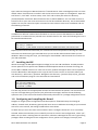
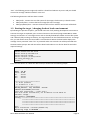
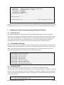
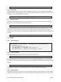
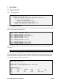
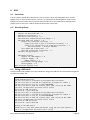
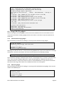
Software User Manual DEVi.MX31 Tinyboards from Bluetechnix www.bluetechnix.com Contact Bluetechnix Mechatronische Systeme GmbH Waidhausenstrasse 3/19 A‐1140 Vienna AUSTRIA / EUROPE [email protected] http://www.bluetechnix.com http://www.tinyboards.com Document No.: 100‐2410‐2.3‐SUM Document Revision 3 Date: 2008‐10‐09 DEV‐i.MX31 Software User Manual Page 2 Edition 2008‐09 © Bluetechnix Mechatronische Systeme GmbH 2007 All Rights Reserved. The information herein is given to describe certain components and shall not be considered as a guarantee of characteristics. Terms of delivery and rights of technical change reserved. We hereby disclaim any warranties, including but not limited to warranties of non‐infringement, regarding circuits, descriptions and charts stated herein. Bluetechnix makes and you receive no warranties or conditions, express, implied, statutory or in any communication with you. Bluetechnix specifically disclaims any implied warranty of merchantability or fitness for a particular purpose. Bluetechnix takes no liability for any damages and errors causing of the usage of this board. The user of this board is responsible by himself for the functionality of his application. He is allowed to use the board only if he has the qualification. More information is found in the General Terms and Conditions (AGB). Information For further information on technology, delivery terms and conditions and prices please contact Bluetechnix (http://www.bluetechnix.com). Warning Due to technical requirements components may contain dangerous substances. The Core Modules and development systems contain ESD (electrostatic discharge) sensitive devices. Electro‐static charges readily accumulate on the human body and equipment and can discharge without detection. Permanent damage may occur on devices subjected to high‐ energy discharges. Proper ESD precautions are recommended to avoid performance degradation or loss of functionality. Unused Core Modules and Development Boards should be stored in the protective shipping DEV‐i.MX31 Software User Manual Page 3 Contents 1 Setting up a development environment (using OpenSuSE 10.2) .................................................... 7 1.1 1.2 1.3 1.4 1.5 1.6 1.7 1.8 1.9 2 Setting up an environment (using Ubuntu 8.04 Beta) .................................................................. 13 2.1 2.2 2.3 2.4 3 Hardware requirements .......................................................................................................... 7 Software requirements ........................................................................................................... 7 Installing LTIB ........................................................................................................................... 8 Connecting the Development Board ....................................................................................... 9 Setting up required services .................................................................................................. 10 Creating links to the Linux installation .................................................................................. 10 Installing the BSP ................................................................................................................... 11 Configuring and compiling the Kernel ................................................................................... 11 Booting the target / changing the boot loader environment ............................................... 12 General notes ........................................................................................................................ 13 Installation of Ubuntu ........................................................................................................... 13 Installing LTIB ......................................................................................................................... 13 Enabling network services ..................................................................................................... 14 MC13783 (ATLAS) .......................................................................................................................... 16 3.1 Charger / LiCell ...................................................................................................................... 16 3.1.1 3.1.2 3.2 Lighting .................................................................................................................................. 16 3.2.1 3.2.2 3.3 3.4 Kernel options ............................................................................................................... 17 Test sound files .............................................................................................................. 17 Playing audio ................................................................................................................. 17 Recording audio ............................................................................................................. 18 Playing an mp3 file ........................................................................................................ 18 NAND Flash .................................................................................................................................... 19 4.1 4.2 5 Kernel options ............................................................................................................... 16 Unit Tests ....................................................................................................................... 17 Touch screen ......................................................................................................................... 17 Audio ..................................................................................................................................... 17 3.4.1 3.4.2 3.4.3 3.4.4 3.4.5 4 Overview ........................................................................................................................ 16 Unit Tests ....................................................................................................................... 16 Kernel options ....................................................................................................................... 19 Using the NAND flash ............................................................................................................ 19 NOR Flash ...................................................................................................................................... 20 5.1 Spansion Flash ....................................................................................................................... 20 5.1.1 5.1.2 5.2 Kernel options ............................................................................................................... 20 Using the NOR flash ....................................................................................................... 20 Intel Strata Flash .................................................................................................................... 21 DEV‐i.MX31 Software User Manual Page 4 5.2.1 5.2.2 6 USB ................................................................................................................................................ 22 6.1 6.2 6.3 6.4 Overview ................................................................................................................................ 22 Kernel options ....................................................................................................................... 22 Using a USB stick ................................................................................................................... 22 Using USB OTG gadgets ......................................................................................................... 23 6.4.1 6.4.2 6.4.3 6.5 7 USB host 2 and devices requiring more than 150mA ............................................................ 24 Kernel options ....................................................................................................................... 25 Using the card ........................................................................................................................ 25 UART .............................................................................................................................................. 26 8.1 8.2 9 File backed storage gadget ............................................................................................ 23 Ethernet gadget ............................................................................................................. 23 Serial gadget .................................................................................................................. 24 SD‐Cards ........................................................................................................................................ 25 7.1 7.2 8 Kernel options ............................................................................................................... 21 Using the NOR flash ....................................................................................................... 21 Overview ................................................................................................................................ 26 Testing ................................................................................................................................... 26 Keypad ........................................................................................................................................... 26 9.1 9.2 Kernel options ....................................................................................................................... 26 Testing ................................................................................................................................... 26 10 Video‐Out ...................................................................................................................................... 27 10.1 Hitachi 3.5’’ TFT (240 x 320) with touch screen .................................................................... 27 10.2 Sharp 12.1’’ TFT (800 x 600) .................................................................................................. 27 11 Video‐In ......................................................................................................................................... 28 11.1 TVP5150 ................................................................................................................................. 28 11.1.1 11.1.2 Kernel options ............................................................................................................... 28 Using the TVP5150 ........................................................................................................ 28 11.2 OV2640 .................................................................................................................................. 28 11.2.1 11.2.2 Kernel options ............................................................................................................... 28 Using the OV2640 .......................................................................................................... 29 12 Modifying the boot loader ............................................................................................................ 30 12.1 12.2 12.3 12.4 Prerequisites .......................................................................................................................... 30 Building a new boot loader ................................................................................................... 30 Flashing the boot loader image ............................................................................................. 30 Changing the environment settings ...................................................................................... 30 13 Freescale ADS HAB ToolKit ............................................................................................................ 31 DEV‐i.MX31 Software User Manual Page 5 13.1 Boot mode switches .............................................................................................................. 31 13.2 Advanced ToolKit ................................................................................................................... 31 14 Document revision history ............................................................................................................ 32 DEV‐i.MX31 Software User Manual Page 6 1 Setting up a development environment (using OpenSuSE 10.2) 1.1 Hardware requirements To start you should meet the follow minimum hardware requirements. PC with x86 compatible CPU (32bit preferred) CPU ≥ 1 GHz RAM ≥ 1024 MB free USB port and/or free COM port Dev‐iMX31 Development Board (included) CM‐iMX31 Core Module (included) USB client‐to‐host Cable (included) or a RS232 null modem cable Ethernet cable (included) 1.2 Software requirements During the development phase, the following tools were used. Windows XP SP2 VMware 6.0 OpenSuSE 10.2 LTIB Revision 5 PuTTY for terminal access Windows is used as the main operating system which hosts Linux as guest operating system inside the virtual machine environment created by VMware. Of course, using a pure Linux based development station would be fine as well. This guide was specifically written for OpenSuSE 10.2. It is possible that the following tasks work on a different distributions just fine, although this cannot be guaranteed. An alternative to OpenSuSE would be Ubuntu. More specific details concerning Ubuntu can be found later in this manual. OpenSuSE will be used to build the LTIB (Linux Target Image Builder) packages and the kernel. It will also offer TFTP (Trivial File Transfer Protocol) and NFS (Network File System) services. To allow access from Windows to the LTIB directory, SMB (Server Message Block) will be used. Note: Throughout all tutorials in this file, a user named “dev” was assumed. Do not confuse this with the /dev directory which can be found on Linux machines. The directory “/home/dev/” refers to the home directory of this user. Start VMware and create a new „Typical Virtual Machine” configuration. Choose Linux as guest operating system and select "Other Linux 2.6.x kernel 32bit". Enter a descriptive name for the machine. Choose the network settings which are appropriate for your network. During the development phase, bridged networking was used. The network was configured to use an automatically assigned IP address for the Windows installation and a fixed IP address for the Linux installation. Choose a disk size of about 30GB, depending on your available space and requirements. Remove the sound adapter and the floppy from the machine; they will most likely not be used. If possible, allow the machine to use 512 MB RAM or more. Now either load a real OpenSuSE 10.2 disk or use VMware's ISO feature to load an ISO image. When booting, press ESC to select your disc drive as boot device. The OpenSuSE installation is started. DEV‐i.MX31 Software User Manual Page 7 During installation you will be asked for a selection of packages. Choose at least the following options. OpenSuSE Base System YaST System Administration KDE Desktop Environment KDE Base System X Window System Fonts File server Base Development If you need other packages check these as well. Make sure that all dependencies are solved. The installation will start and after a reboot you will be prompted for a root password, hostname and domain name. Disable the firewall and IPv6. Setup your network adapters according to your network settings. After rebooting, you will be presented with your chosen desktop. Note: During development the following network settings were used. These are also pre‐programmed on delivery of the Dev‐i.MX31 Development Kit. These are also the defaults for the Bluetechnix Board Support Package (BSP). Of course these could be changed at any time. IP Address for the Target: 192.168.0.51 IP Address for the Linux installation: 192.168.0.75 Broadcast: 255.255.255.0 Gateway: 192.168.0.1 Name server: 192.168.0.1 Set the IP Address of the Linux installation accordingly. This can be done e.g. via YaST2 which can be found in System Menu Computer Administrator Settings. You will need to provide your root password. Navigate to Network Devices Network Card. You should be able to change your IP address to the desired settings. You can check if your settings were successful by running ifconfig in a terminal. It is recommended to use a static instead of a dynamically assigned IP address. Now make sure you can reach the Linux installation e.g. by establishing a SSH Session using PuTTY. The SSH Server is enabled by default. If this does not work, you will need to refine your firewall or network settings. 1.3 Installing LTIB Download the ISO Image labeled LTIB Revision 5 from the Freescale website, if you have not already done so. In VMware, insert the virtual disc into the disc drive. The Linux installation should now show a dialog telling the user that a new disc was entered. In some cases, the disc will not be recognized by the Linux distribution. This can be solved by manually disconnecting and reconnecting the disc drive in VMware. The entered image will be mounted on /media/ltib. Open an SSH Session (e.g. by using PuTTY) to your Linux VM (or use the terminal) in order to install LTIB. Make sure you are logged in as a normal user and not as root. /media/ltib/install DEV‐i.MX31 Software User Manual Page 8 You will be asked to accept the license agreement. Press Y to continue. A list of packages will be shown. You can either scroll to the end or press Ctrl‐C to go on directly. Answer "yes" and you will be asked for the installation location. Simply enter tilde (~) to select your home directory. A subdirectory will automatically be created. The installation script will now copy various files to your selected location. After the installation is complete, navigate to your home directory; create a symbolic link (not necessary, but useful) and then run LTIB for the first time. ln ‐s ltib‐imx31ads‐20071008 ltib5 cd ~/ltib5 ./ltib LTIB will warn that it requires root rights (privileges) for some tasks and will also automatically provide a solution. Run the following command and add the given line to the file. sudo /usr/sbin/visudo Save the file and run the “ltib” command again. The following process might take a while. 1.4 Connecting the Development Board In the meanwhile you can connect the Development Board to your computer. You will now have to decide whether you will use a Windows Terminal program such as PuTTY or a Linux terminal program such as Minicom. In this part, all operations were performed using PuTTY in Windows. Minicom could be installed by using YaSTs Software Management Feature. Use the search box to search for "minicom". VMware handles its USB devices in such a way, that when you connect a USB device whilst the virtual machine has the focus, it will capture the device which will then only be usable in the virtual machine. If the virtual machine does not have the focus, the device will be accessible in Windows only. If you connect the device while the virtual machine has the focus it will most likely be known as /dev/ttyUSB0. You can simply check this with the following command. ls /dev/ttyU* If you connect it when the virtual machine does not have the focus, you can find it's assigned virtual COM port in the device manager which can be reached via Start Run compmgmt.msc. In these instructions we will assume, that COM5 was assigned. Connect the USB cable to the plug labeled USB2UART and connect the network cable to the plug named ETH‐DEV (the Ethernet connector on the shorter side of the Development Board). Windows (or Linux) will now detect a new device and will most likely install drivers for it if needed. Linux should already have the drivers built into the kernel and therefore should not need any additional files. The driver for Microsoft Windows is included on the support CD. Linux kernels higher than 2.6.14 already have support built into them; no special driver is required in this case. DEV‐i.MX31 Software User Manual Page 9 Figure 1 ‐ Development board connection setup 1.5 Setting up required services Open YaST2 and navigate to network services. We will now setup the TFTP service. This is required since the device will retrieve its kernel via TFTP during the normal development process. Choose TFTP server and enable it. Select /home/dev/rootfs/boot as image directory. Click finish to save the settings and close the dialog. Now select the NFS service. Start it and then go to the next page. Add a new directory and enter /home/dev/ltib5/rootfs. As options, type: “rw,no_root_squash,async” and click ok. Save your settings and close the dialog by clicking "Finish". We will also need a link pointing to the rootfs. Bring up a terminal and run the following commands. sudo mkdir /srv/nfs sudo ln ‐s /home/dev/ltib5/rootfs /srv/nfs/rootfs In case you are not using YaST or a graphical environment, the following configuration files might be of interest. * /etc/xinetd.d/tftp (TFTP Service) service tftp { socket_type = dgram protocol = udp wait = yes user = root server = /usr/sbin/in.tftpd server_args = ‐s /home/dev/ltib5/rootfs/boot disable = no } * /etc/exports (NFS Export) /home/dev/ltib5/rootfs *(rw,root_squash,sync) # Restart services after performing these changes /etc/init.d/xinetd restart /etc/init.d/nfsserver restart 1.6 Creating links to the Linux installation If you are using Windows as main platform and if you are running the Linux installation in a virtual machine, you might want to create samba shares to have direct access to the files. If you do not need or want this, you can simply skip this chapter. DEV‐i.MX31 Software User Manual Page 10 Open YaST2 and navigate to Network Services Samba Server. Enter a Workgroup name or use the default. Select "Not a domain controller" and set the service start option to "During Boot". Open the tab "Shares", click "Add". As share name, enter "ltib" and as share path select the directory /home/dev/ltib5. Click finish. We will now also have to add an SMB user. You can either choose to have the root or your user name to have access to the ltib installation directory. The recommended option is to use your username. Open a terminal or PuTTY session to the Linux installation and run the following command. sudo smbpasswd ‐a username In addition we will now create a batch file which we can run to access the SMB share in Windows (also known as a network share). We will use a network drive for this. Paste the following lines into a file named accessShare.bat. @echo off net use y: /delete net use y: \\192.168.0.75\ltib password /USER:username /Persistent:No Replace password and username with your selected username and password. Running this command will make sure the directory gets mounted when you run the file and unmounted when you exit Windows. When running the script, you should get a drive labeled Y which contains the contents of your ltib installation. 1.7 Installing the BSP We will now apply the BSP (Board Support Package) to our raw LTIB installation. The BSP provides various patches for this specific Core Module and Development Board. At the time of writing, the current BSP is labeled revision 175. From time to time, updates will appear which can be requested from the Bluetechnix i.MX support team. Copy the most current revision to a location within your user directory; I will assume ~/patchset. Navigate to the directory ~/patchset /bsp‐r5/mxc_patchset and run the installation program. The commands are listed below. cd ~/patchset tar xfz BLT‐BSP$rev$ cd bsp‐r5/mxc_patchset ./install ~/ltib5 This will copy the files to the appropriate locations and will execute the patches. You should not see any error messages during this process (only informative messages). Answer the two following questions with y. The screen now shown will be usually referred to as “package configuration menu”. 1.8 Configuring and compiling the Kernel Navigate to Target System Configuration and select Options Network Setup and change IP address, network mask, broadcast, gateway and name server IP addresses according to your network structure. In this tutorial, the settings noted before were chosen. Go back until you are at the main screen and then select "Configure the kernel" if it is not already selected. Select Exit and when you are asked if you want to save the new configuration, select “yes”. Make sure you have a working internet connection; otherwise LTIB might fail if it tries to get missing packages. When reaching the kernel configuration screen, perform no changes, but simply click DEV‐i.MX31 Software User Manual Page 11 “Exit”. The following process might take a while. It should end without any errors and you should receive the message "Build succeeded" at the end. The following directories will have been created: ltib5/rootfs ‐ contains the root file system for the target; this directory is shared via NFS ltib5/rootfs/boot ‐ contains the kernel image (file name: uImage) ltib5/rpm/BUILD/linux ‐ contains the kernel sources from which a new kernel will be built 1.9 Booting the target / changing the boot loader environment By following the previous chapters, you should now have a fully working development environment. Connect the target as explained, open a terminal session to the board (using 115200 8N1 as UART settings) and switch it on. The target comes with an already flashed boot loader and root file system and is basically fully working. On delivery, the target boots from this flashed environment. To change this, you will need to enter the boot loader’s command shell. When the boot loader displays the message “Enter password” enter “blt” as password within one second. You will be presented with the boot loaders prompt. We will now tell the boot loader where it can find its boot file and other required settings. setenv ipaddr 192.168.0.51 setenv netmask 255.255.255.0 setenv serverip 192.168.0.75 setenv bootfile uImage setenv rootpath /srv/nfs/rootfs run setup_bootargs_net saveenv Press the reset button or reboot the device and you should see the following output. U‐Boot 1.2.0 (Sep 8 2008 ‐ 07:04:13) DRAM: 128 MB Flash: 40 MB In: serial Out: serial Err: serial ****************************** *** Enter password *** autoboot in 1 sec... ****************************** DRIVER_VERSION : 100, DATECODE : 092706 LAN9x18 (0x92110000) detected. start Auto negotiation... (take ~2sec) TFTP from server 192.168.0.75; our IP address is 192.168.0.51 Filename 'uImage'. Load address: 0x80100000 Loading: *************************************************************** *************************************************************** *************************************************************** *************************************************************** *************************************************** done Bytes transferred = 1579764 (181af4 hex) ## Booting image at 80100000 ... DEV‐i.MX31 Software User Manual Page 12 Image Name: imageName Image Type: ARM Linux Kernel Image (uncompressed) Data Size: 1579700 Bytes = 1.5 MB Load Address: 80300000 Entry Point: 80300000 Verifying Checksum ... OK OK Starting kernel ... Uncompressing Linux.......................... done, booting the kernel. Should you encounter any errors during this process, please consult the regularly updated version of the frequently asked questions on the internet which can be accessed via the Bluetechnix website. 2 Setting up an environment (using Ubuntu 8.04 Beta) 2.1 General notes Essentially everything works according to the (more detailed) OpenSuSE 10.2 setup description, except for a few changes at the beginning and when setting up the network services needed. These steps will be described here. You might still want to read through the OpenSuSE explanation since non Ubuntu specific details won't be discussed here. If you have a question, please check the OpenSuSE instructions first. Please note that Ubuntu releases seem to change quite a bit. 2.2 Installation of Ubuntu Perform a normal Ubuntu installation. Leave all settings as default, only change the settings for time and keyboard layout as needed. You may also choose a different partitioning scheme. After the last reboot, login with your chosen username and password, open a terminal window and run the following commands (you will need an internet connection to do this). sudo apt‐get update sudo apt‐get install libc6‐dev sudo apt‐get install libgcc1 sudo apt‐get install patch sudo apt‐get install bison sudo apt‐get install rpm sudo apt‐get install zlib‐bin sudo apt‐get install zlib1g‐dev sudo apt‐get install ncurses‐dev sudo apt‐get install build‐essential 2.3 Installing LTIB Now you may install LTIB by inserting your disc or mounting your image and running /media/cdrom/install. You will be asked where you want to install LTIB. Enter ~ as directory. This will install it into your home directory. After the installation is complete, change to your home directory and enter the following command to create a link. Change to the LTIB installation directory and run LTIB for the first time. cd ~ ln ‐s ltib‐imx31ads‐20071008 ltib5 DEV‐i.MX31 Software User Manual Page 13 cd ~/ltib5 ./ltib If it complains about missing packages you probably haven't run all the apt‐get commands above. If it complains about not having su (superuser) rights for different operations run the su command, and enter your user password, then perform the steps given in the instructions. The following operation might take a while. 2.4 Enabling network services We will now enable SMB and NFS support for the target and the host. Add SMB and NFS support using the Synaptic Package Manager, then run sudo vim /etc/exports and change the content as shown below. /home/user/ltib‐imx31ads‐20071008 *(rw,no_root_squash,async) To make NFS work, we need to create the following symbolic link. After performing these changes, you need to restart the NFS server. sudo mkdir /srv/nfs cd /srv/nfs sudo ln ‐s /home/dev/ltib5/rootfs rootfs sudo /etc/init.d/nfs‐common restart Ubuntu does not provide a graphical tool to configure TFTPD, so we will have to do this via the shell. Run the following commands. sudo apt‐get install xinetd tftpd tftp Create /etc/xinetd.d/tftp and add this entry. service tftp { protocol = udp port = 69 socket_type = dgram wait = yes user = nobody server = /usr/sbin/in.tftpd server_args = /home/user/ltib‐imx31ads‐20071008/rootfs/boot disable = no } After restarting the xinet daemon, the TFTP service is up and running. sudo /etc/init.d/xinetd restart If you need SSH access (e.g. for a PuTTY Session) you might want to install the SSH server. This can be done by running the following command. sudo apt‐get install openssh‐server. Ubuntu doesn't enable a root account by default. Should you need it, you can use sudo ‐s, and then run passwd to set a new password. DEV‐i.MX31 Software User Manual Page 14 Concerning the network setup, Ubuntu seems to have troubles with the virtual machine network interface. You might want to edit the file /etc/network/interfaces by hand and then restart networking. sudo /etc/init.d/networking restart To continue, the next steps can be found in the OpenSuSE instructions. DEV‐i.MX31 Software User Manual Page 15 3 MC13783 (ATLAS) 3.1 Charger / LiCell 3.1.1 Overview Two different types of batteries are available on the Development Board. A LiIo battery can be connected to the connector which is located left of the two buttons labeled S305 and S301. The connector itself is labeled X201. Please check for the correct polarity, since this terminal is not protected against reversed polarity. The GND Pin has to be connected to Pin 1; the positive Voltage is connected to Pin 3. The second battery is an ultra cap which is located close to the IPU connector. 3.1.2 Unit Tests Different unit tests are available for the PMIC (Power Management IC) battery section. They can be found in the directory /unit_tests/mxc_pmic_testapp. Example commands are shown here. # Test charger management, test should end in PASS ./pmic_testapp_battery ‐T0 # Test the LED # You will see the LED lighting for about 1 second mx31# ./pmic_testapp_battery ‐T2 The MC13783 companion chip is able to charge a battery. To test this feature, the following commands are useful. # Display help information, also shows charging modes atlas‐charger ‐‐help # Read battery voltage # While charging, perform multiple reads throughout a minute # to see the battery voltage rising atlas‐charger ‐b # Charge the attached battery with given current and voltage # Do not use more than 350mA without heatsink # The values for parameter ‐e are displayed in the help screen atlas‐charger ‐e7,3 # Disable charging of the LiIon battery atlas‐charger ‐d # Read backup battery (LiCell) voltage atlas‐charger ‐l # Charge the LiCell battery atlas‐charger ‐L7 # Disable charging of the LiCell battery atlas‐charger ‐D 3.2 Lighting 3.2.1 Kernel options Device Drivers ‐> MXC Support Drivers ‐> MXC PMIC Support ‐> DEV‐i.MX31 Software User Manual Page 16 MC13783 Light and Backlight Support Y 3.2.2 Unit Tests Testing the lighting system of the PMIC is a straight forward task. Connect a keypad module to the keypad connector, boot the device, then run the following command on the target. This will flash all the LEDs on the keypad module for four times. ./unit_tests/mxc_pmic_test/pmic_testapp_light ‐T 8 3.3 Touch screen The ADC performs various functions, e.g. the touch screen uses it to detect the position of the pen tip. This test can be easily made. Run the command /unit_tests/mxc_pmic_test/pmic_testapp_adc ‐T TS If you hold down the pen on the touch screen, you will be able to see the coordinates. If not, you will receive the message that the test failed, since no valid coordinates were detected. You can also manually read out the values by running the following command, the channels 12‐15 represent X and Y values. /unit_tests/mxc_pmic_test/pmic_testapp_adc ‐T CONV 3.4 Audio 3.4.1 Kernel options Device Driver ‐> Sound Support ‐> Y Device Driver ‐> Sound Support ‐> Advanced Linux Sound Architecture ‐> Y OSS Mixer API ‐> Y OSS PCM (digital audio) API ‐> Y Alsa ARM Devices ‐> MXC PMIC sound System ‐> Y Alsa ARM Devices ‐> Playback stream mixing ‐> N (!!!) 3.4.2 Test sound files Run the following command on the host system in the LTIB directory. ./ltib ‐m prep ‐p mxc‐misc This will unpack the misc package which you can find in ~/ltib5/rpm/BUILD/misc. If you search for *.wav files you will find a directory containing about 15 different wave files named with the following scheme. audio$SampleFrequency$$BitsPerSample$$Mono/Stereo$.wav Copy these to the directory ~/ltib5/rootfs/tmp so they will be available on the target. 3.4.3 Playing audio Two different sources for audio exist. You can either play audio on the stereo DSP, which can handle sample frequencies up to 96 kHz, stereo. Alternatively you can play audio on the voice codec, which DEV‐i.MX31 Software User Manual Page 17 can play audio files sampled at 8 kHz or 16 kHz, mono only. To play an audio file on the voice codec submit the command. aplay ‐N ‐M ‐D hw:0,1 audio16k16M.wav # or aplay ‐N ‐M ‐D hw:0,1 audio8k16M.wav Note that you cannot play files with a higher sample rate than 16 kHz or with more than one channel on the voice codec. To play an audio file on the stereo DSP, run the command below. Note that you can play audio files up to 96 kHz in stereo. aplay ‐N ‐M ‐D hw:0,0 audio44k16M.wav # or aplay ‐N ‐M audio16k16S.wav 3.4.4 Recording audio Recording is only possible through the use of the voice codec. To record audio in maximum quality run the command. # This will record 10 seconds of audio (mono/16kHz) on the voice codec arecord ‐r 16000 ‐c 1 ‐f S16_LE ‐N ‐M ‐d 10 recording.wav To play the recorded file use the commands listed below, depending on the device you want to use. aplay ‐N ‐M ‐D hw:0,1 recording.wav # or aplay ‐N ‐M ‐D hw:0,0 recording.wav 3.4.5 Playing an mp3 file Make sure that the package madplay was enabled in the package configuration. To play an mp3 file simply run the command. madplay file.mp3 DEV‐i.MX31 Software User Manual Page 18 4 NAND Flash 4.1 Kernel options Device Drivers ‐> Memory Technology Device Support ‐> NAND Device Support ‐> MXC NAND Support This driver is needed for the hardware related layer. Everything on top is already built into the linux distribution. 4.2 Using the NAND flash To see which partitions are available, run the following command. You should see an output similar to the one below. mx31# cat /proc/mtd dev: size erasesize name mtd0: 00080000 00020000 "Bootloader" mtd1: 00080000 00020000 "Bootloader env" mtd2: 00200000 00020000 "Kernel" mtd3: 01d00000 00020000 "rootfs" mtd4: 00040000 00020000 "IPL‐SPL" mtd5: 00400000 00020000 "nand.kernel" mtd6: 01600000 00020000 "nand.rootfs" mtd7: 065c0000 00020000 "nand.userfs" The output will show both NAND and NOR devices. Typically the NAND devices start with the IPL_SPL partition, so most likely the partitions behind that one will be NAND partitions. We will now erase one partition and create a file system on top of it, then mount it. # Erase partition #7 flash_eraseall ‐j /dev/mtd/7 # Create a filesystem from a directory (/etc) and write to a file mkfs.jffs2 ‐n ‐d /etc ‐o etc.jffs2 # Write the filesystem onto the partition nandwrite ‐a ‐p /dev/mtd/7 etc.jffs2 # Create a mount point for the partition/fs mx31# mkdir /mnt/mtd7a # Mount the file filesystem mx31# mount ‐t jffs2 /dev/mtdblock/7 /mnt/mtd7a # Display the contents of the filesystem mx31# ls /mnt/mtd7a # You should see the same files that are in /etc Files you copy to the NAND file system will be available even after you reboot the device. DEV‐i.MX31 Software User Manual Page 19 5 NOR Flash 5.1 Spansion Flash 5.1.1 Kernel options Device Drivers ‐> Memory Technology Device Support ‐> RAM/ROM Flash Chip Drivers Flash Chip Driver advanced configuration options ‐> Y Specific CFI Flash Geometry ‐> Y Support 16 bit Buswidth ‐> Y Support 1 chip flash interleave ‐Y Support for Intel/Sharp flash chips ‐> Y Support for AMD/Fujitsu flash chips ‐> Y 5.1.2 Using the NOR flash To get information about the flash devices run the following command. Typically all partitions before the IPL_SPL partition are NOR devices. mx31# cat /proc/mtd dev: size erasesize name mtd0: 00080000 00020000 "Bootloader" mtd1: 00080000 00020000 "Bootloader env" mtd2: 00200000 00020000 "Kernel" mtd3: 01d00000 00020000 "rootfs" mtd4: 00040000 00020000 "IPL‐SPL" mtd5: 00400000 00020000 "nand.kernel" mtd6: 01600000 00020000 "nand.rootfs" mtd7: 065c0000 00020000 "nand.userfs" To test the Spansion flash, you can read the boot loader from this flash by running the following command. dd if=/dev/mtdblock0 of=/tmp/bootpart bs=1024 You will receive a file named bootpart in /tmp which will contain the boot loader. You can check this by opening the file in a hex editor and by seeking to address 0x15580. Around that address, you should see various messages from the boot loader. Unused space at the end will be padded with 0xFF. We will now mount the root file system. # Create a mount point mx31# mkdir /mnt/normnt # Mount rootfs to mountpoint mx31# mount ‐t jffs2 /dev/mtdblock/3 /mnt/normnt # Show contents mx31# ls /mnt/normnt/ bin etc linuxrc proc sys usr dev home mnt root tmp var dir lib opt sbin unit_tests mx31# DEV‐i.MX31 Software User Manual Page 20 Make sure you are not erasing the boot loader or the boot loader’s environment section. If you do, you might need a JTAG programmer to flash the boot loader back to its location. Data written to the NOR flash will exist even after rebooting. Software is able of running directly from the NOR flash. 5.2 Intel Strata Flash 5.2.1 Kernel options Device Drivers ‐> Memory Technology Device (MTD) Support ‐> RAM/Flash chip drivers ‐> Enable Strata Flash ‐> Y 5.2.2 Using the NOR flash To get information about the flash devices run the following commands. By default, the partition which is based on the Strata flash is called “Data”; in this case it is mtd4. The partitions before that one are Spansion flash partitions. Partitions behind the Strata are usually NAND type partitions. mx31# cat /proc/mtd dev: size erasesize name mtd0: 00080000 00020000 "Bootloader" mtd1: 00080000 00020000 "Bootloader env" mtd2: 00200000 00020000 "Kernel" mtd3: 01d00000 00020000 "rootfs" mtd4: 00800000 00020000 "Data" We can unlock the device and erase all data on it by using the following commands. mx31# flash_unlock /dev/mtd/4 mx31# flash_eraseall /dev/mtd/4 DEV‐i.MX31 Software User Manual Page 21 6 USB 6.1 Overview The OTG stack is based upon three drivers; the transceiver driver, the OHCI/EHCI driver and the gadget driver. If the transceiver driver is active, it is responsible for deciding which mode is used (peripheral or host). Either the transceiver driver decides this or the loaded driver decides which mode is used. In this case, it will be the driver that chooses the mode. 6.2 Kernel options Device Drivers ‐> USB Support ‐> Support for Host‐Side USB ‐> Y USB Device Filesystem ‐> Y USB device class devices ‐> Y USB selective suspend/resume and wakeup ‐> Y EHCI HCD (USB 2.0) support ‐> M Support for Freescale controller ‐> Y Support for Host 2 port on Freescale controller ‐> Y Support for OTG Host Port on Freescale controller ‐> Y OTG Transceiver ‐> Philips ISP1504 Full Speed ISO Transactions ‐> Y Root Hub Transaction Translators ‐> Y USB Mass Storage Support ‐> M USB Gadget Support Support for USB Gadgets ‐> M Ethernet Gadget ‐> M RNDIS Support ‐> Y File‐backed storage gadget ‐> M Serial gadget ‐> M #set all other options to N 6.3 Using a USB stick Simply load the EHCI module to use the USB device. Plug in the USB stick and it should be recognized as a SCSI removable disk. # Load the module mx31# modprobe ehci‐hcd fsl‐ehci fsl‐ehci.0: Freescale On‐Chip EHCI Host Controller fsl‐ehci fsl‐ehci.0: new USB bus registered, assigned bus number 1 fsl‐ehci fsl‐ehci.0: irq 36, io mem 0x43f88400 fsl‐ehci fsl‐ehci.0: USB 2.0 started, EHCI 1.00, driver 10 Dec 2004 usb usb1: configuration #1 chosen from 1 choice hub 1‐0:1.0: USB hub found hub 1‐0:1.0: 1 port detected fsl‐ehci fsl‐ehci.1: Freescale On‐Chip EHCI Host Controller fsl‐ehci fsl‐ehci.1: new USB bus registered, assigned bus number 2 fsl‐ehci fsl‐ehci.1: irq 37, io mem 0x43f88000 fsl‐ehci fsl‐ehci.1: USB 2.0 started, EHCI 1.00, driver 10 Dec 2004 usb usb2: configuration #1 chosen from 1 choice hub 2‐0:1.0: USB hub found hub 2‐0:1.0: 1 port detected # Plug in the USB device mx31# usb 1‐1: new full speed USB device using fsl‐ehci and address 2 usb 1‐1: configuration #1 chosen from 1 choice DEV‐i.MX31 Software User Manual Page 22 Initializing USB Mass Storage driver... scsi0 : SCSI emulation for USB Mass Storage devices usbcore: registered new interface driver usb‐storage USB Mass Storage support registered. scsi 0:0:0:0: Direct‐Access UrDisk USB FLASH DISK 1.00 PQ: 0 ANSI: 2 sd 0:0:0:0: [sda] 256000 512‐byte hardware sectors (131 MB) sd 0:0:0:0: [sda] Write Protect is off sd 0:0:0:0: [sda] Assuming drive cache: write through sd 0:0:0:0: [sda] 256000 512‐byte hardware sectors (131 MB) sd 0:0:0:0: [sda] Write Protect is off sd 0:0:0:0: [sda] Assuming drive cache: write through sda: sda1 sd 0:0:0:0: [sda] Attached SCSI removable disk # Perform some operations mx31# mkdir /mnt/usbstick mx31# mount /dev/sda1 /mnt/usbstick mx31# ls /mnt/usbstick 6.4 Using USB OTG gadgets Before running any of these gadgets, make sure that the module ehci‐hcd is not loaded. You can unload ehci‐hcd before loading a gadget and vice versa but no two drivers must be loaded at the same time. 6.4.1 File backed storage gadget Run the following commands for loading or removing the file backed storage gadget. # Load the module modprobe g_file_storage file=/dev/ram0 # Unload the module modprobe ‐r g_file_storage Now plug the cable into the PC. In case you are using Windows XP or Vista you should see a message stating that a new drive was found. The Linux console will print the following message. g_file_storage gadget: high speed config #1 Open the device manager in Windows (Start Run compmgmt.msc). In “Drives” you will see the entry "Linux File‐Store Gadget USB Device". Open Disk Management. Windows will ask you to initialize the device. Just press OK and you will see a new 16 MB Device. If you partition and format that device and assign a drive letter to it, Windows will show it in the Explorer. 6.4.2 Ethernet gadget Run the following commands for loading or removing the file backed Ethernet gadget, then attach a cable to the USB OTG port. # Load the module modprobe g_ether # Unload the module modprobe –r g_ether DEV‐i.MX31 Software User Manual Page 23 Windows should pop up a message stating that it requires drivers for an Ethernet interface (RNDIS). If you have a linux installation running, run the following commands to test the interface. On the target: ifconfig usb0 10.0.0.2 up On the Linux system: ifconfig usb0 10.0.0.3 up ping 10.0.0.2 6.4.3 Serial gadget Disconnect the cable, reboot the device, then run the following commands # Load the module modprobe g_serial # Unload the module modprobe –r g_serial Detailed documentation about the serial gadget is available at the following location: /home/dev/ltib5/rpm/BUILD/linux/Documentation/gadget_serial.txt. 6.5 USB host 2 and devices requiring more than 150mA USB Host 2 is able to deliver more than 150mA to a device. The USB specification describes 500mA as a maximum value. Since the driver for the ISP1504 is used on both, the second USB host and the OTG port, but only the second USB port is able to source 500mA, a workaround was developed which enables 500mA on that port only. Please be aware that there is no fuse or current limiter in action. Using high current devices which work outside USB specifications might damage the Development Board. DEV‐i.MX31 Software User Manual Page 24 7 SDCards 7.1 Kernel options Device Drivers ‐> MMC/SD Card Support ‐> MMC/SD Card Support MMC Block device driver Use bounce buffer for simple hosts Freescale MXC Multimedia Card Interface support 7.2 Using the card After the device finishes booting, insert an SD Card into the appropriate slot located at the bottom side of the dev board. You should immediately see messages telling you information about the card. mmcblk0: mmc1:b368 SDC 975360KiB mmcblk0: p1 Check if the device node /dev/mmcblk0 exists. ls /dev/mmcblk0 We will now partition and format the card. Make sure no important data is stored on the card, since it will be deleted. Run the following commands. dd if=/dev/zero of=/dev/mmcblk0 bs=1024 count=512 // clear 512 kb fdisk /dev/mmcblk0 // run fdisk // use "o" to delete existing partitions // use "n" to create a new partition // use "w" to write the partition table mkfs.ext2 /dev/mmcblk0p1 // create an ext2 fs mkdir /mnt/mmc1 // create a mountpoint mount ‐t ext2 /dev/mmcblk0p1 /mnt/mmc1 // Mount a partition ls /mnt/mmc1 // view the contents umount /mnt/mmc1 // Unmount sd card DEV‐i.MX31 Software User Manual Page 25 8 UART 8.1 Overview The i.MX31 features 2 separate UART ports. Both of them are connected to the appropriate ports on the Development Board, whereas one is directly attached to the serial interface using a level shifter for RS232 V.24 levels and the other is attached to a USB port using a USB‐to‐UART bridge. Both UARTs can be switched on or off separately by using the following DIP switches on the Development Board. For detailed info please check the Hardware User Manual. USBUART ‐ Enables or disables the UART for the USB connector RS232 ‐ Enables or disables the UART for the serial connector UARTSEL ‐ Switches which UART (#1 or #2) is USB or Serial The first UART is by default configured to 115200 8N1, the second UART is by default configured to 9600 8N1. This can be changed on the linux command line by running the following command. # Configure a baud rate of 115200 on UART2 stty ‐F /dev/mxctty1 115200 8.2 Testing The two UARTs can simply be tested by attaching the appropriate cables and writing text to the serial console using the command listed below. echo "text" >/dev/ttymxc1 9 Keypad 9.1 Kernel options Device Drivers ‐> Input Device Support ‐> Event interface ‐> Y Input Device Support ‐> Keyboards ‐> MXC Keypad driver ‐> Y 9.2 Testing Run the following command to test the keypad functionality. Press some keys. Please note that the keys will not be labeled correctly, since this is application specific. The key map can be changed easily according to your requirements. /unit_tests/mxc_keyb_test/mxc_keyb_test.out DEV‐i.MX31 Software User Manual Page 26 10 VideoOut 10.1 Hitachi 3.5’’ TFT (240 x 320) with touch screen This is the default display device and all kernel settings are already set up for this device. In case something needs to be changed, these entries could be found in the following location. Device Drivers ‐> Graphics Support ‐> Synchronous Panel Framebuffer. 10.2 Sharp 12.1’’ TFT (800 x 600) Please contact Bluetechnix for support information. DEV‐i.MX31 Software User Manual Page 27 11 VideoIn It is only allowed to have one device at a time active, since both the TVP5150 and the OV2640 drive the same signals. Therefore it is only allowed to activate a single device in the kernel configuration. 11.1 TVP5150 11.1.1 Kernel options Device Drivers ‐> Multimedia Devices Enable Video For Linux API 1 (DEPRECATED) ‐> N Enable Video For Linux API 1 compatible Layer ‐> Y Video Capture Adapters Enable advanced debug functionality ‐> N Autoselect pertinent encoders/decoders ‐> Y MXC Video for Linux Camera ‐> M MXC Camera/V4L2 PRP Features support Micron mt9v111 camera support ‐> N Magnachip mc521da camera support ‐> N OmniVision ov2640 camera support ‐> N TI TVP5150 video Decoder Support ‐> M ITU‐R BT.656 8‐bit 4:2:2 with embedded syncs ‐> Y TI TVP5150 video decoder support ‐> Y Pre Processor VF SDC library ‐> M Pre Processor Encoder Library ‐> M MXC Video for Linux Video Output ‐> M 11.1.2 Using the TVP5150 To enable the TVP5150, place the jumper on the ADP‐CSI onto its position (or solder in R13) so the level shifter will be enabled. After performing these changes, you can run the following commands. # Load Video4Linux2 module modprobe mxc_v4l2_in # Load TVP5150 capture module modprobe tvp5150_capture # Record 320x240px, 30 frames, yuv 420 format /unit_tests/mxc_v4l2_test/mxc_v4l2_capture.out ‐w 320 ‐h 240 ‐c 30 f.yuv # Display image from TVP5150 on display (240 x 320, rotated) /unit_tests/mxc_v4l2_test/mxc_v4l2_overlay.out –ow 240 –oh 320 –r 4 11.2 OV2640 11.2.1 Kernel options Device Drivers ‐> Multimedia Devices Enable Video For Linux API 1 (DEPRECATED) ‐> N Enable Video For Linux API 1 compatible Layer ‐> Y Video Capture Adapters Enable advanced debug functionality ‐> N Autoselect pertinent encoders/decoders ‐> Y MXC Video for Linux Camera ‐> M MXC Camera/V4L2 PRP Features support Micron mt9v111 camera support ‐> N Magnachip mc521da camera support ‐> N OmniVision ov2640 camera support ‐> M DEV‐i.MX31 Software User Manual Page 28 TI TVP5150 video Decoder Support ‐> N Pre Processor VF SDC library ‐> M Pre Processor Encoder Library ‐> M MXC Video for Linux Video Output ‐> M 11.2.2 Using the OV2640 To enable the OV2640, remove the jumper on the ADP‐CSI so the level shifter will be deactivated. After performing these changes, you can run the following commands. # Load Video4Linux2 module modprobe mxc_v4l2_in # Load OV2640 capture module modprobe ov2640_camera # Record 320x240px, 30 frames, yuv 420 format /unit_tests/mxc_v4l2_test/mxc_v4l2_capture.out ‐w 320 ‐h 240 ‐c 30 f.yuv # Display image from TVP5150 on display (240 x 320, rotated) /unit_tests/mxc_v4l2_test/mxc_v4l2_overlay.out –ow 240 –oh 320 –r 4 DEV‐i.MX31 Software User Manual Page 29 12 Modifying the boot loader 12.1 Prerequisites You will need at least the following to successfully build and deploy a new boot loader. Working LTIB installation JTAG Programmer (e.g. PEEDI from Ronetix) Core Module on the Development Board 12.2 Building a new boot loader Change to the directory where your LTIB installation is located. Then run the following command. ./ltib ‐m prep ‐p u‐boot This will unpack the u‐boot files to ./rpm/BUILD/u‐boot‐$version$. You can now edit these files as desired. To finally create the boot loader image, run the following commands. ./ltib ‐m scbuild ‐p u‐boot ./ltib –m scinstall –p u‐boot ./ltib –m scdeploy –p u‐boot This will create the file u‐boot.bin which will be copied to ~/ltib5/rootfs/boot. Make sure that the copy process finished successfully and that the file creation time of the new image is roughly the current time. 12.3 Flashing the boot loader image Now connect the JTAG to the Development Board. Start the JTAG programmer. If you are using PEEDI, use the following commands to flash the boot loader image. flash erase 0xa0000000 0x100000 flash program tftp://192.168.0.75/u‐boot.bin bin 0xa0000000 12.4 Changing the environment settings After flashing, all your environment settings will be reset to default ones and you will have to renew them. To do so, enter the boot loader prompt and run the following commands. Keep in mind that the settings shown are only example settings and do not represent your setup. BTi.MX31$ setenv ethaddr 00:00:e2:a2:66:12 BTi.MX31$ setenv ipaddr 192.168.0.51 BTi.MX31$ setenv serverip 192.168.0.75 BTi.MX31$ setenv bootfile uImage BTi.MX31$ run setup_bootargs_net BTi.MX31$ saveenv Saving Environment to Flash... Un‐Protected 1 sectors Erasing Flash... . done Erased 1 sectors Writing to Flash... done Protected 1 sectors DEV‐i.MX31 Software User Manual Page 30 13 Freescale ADS HAB ToolKit The Advanced ToolKit from Freescale can be used for flashing any image to the NOR Flash. (Note: only the Spansion flash S71xxx is supported, for other flash types you need an own lib!) 13.1 Boot mode switches You have to switch all boot modes DIP switches to ON before you switch ON the Power on the Target Board. 13.2 Advanced ToolKit Connect the USB Cable on the USB to UART Bridge or on the SUB‐D UART Connector (Note: Set the correct DIP Switches on S1.1 and S1.2!). Start the ADS HAB Toolkit from Freescale. ‐ ‐ ‐ ‐ ‐ ‐ ‐ ‐ ‐ ‐ ‐ ‐ ‐ ‐ ‐ ‐ ‐ ‐ ‐ ‐ select the i.MX CPU Type to i.MX31 TO2 enable DDR as Device memory initial file (only if you have the 128MB DDR Version, for other DDR Settings you have to make your own init file – contact Bluetechnix for more information) Select the Serial Port you have connected Go to the next windows with the button “Next >” Select the “Flash Tool” Button Click on the Button “Go” Select the Operation type – for flashing use “Program” Select the Flash model (NOR S71WS256ND0. Note if you have the S29 Spansion type the ADS will program the Flash but cannot verify the flash. You have to try this in the case of the S29 Spansion flash) The Address field should be 0xa0000000 Select the image file you want to program on the flash Set DIP Switch S1.5 (CLKSS) to ON Power ON the Board Click on Execute Wait until the Tool has flashed the image Switch OFF the Board Close the Programm Set DIP Switch S1.5 (CLKSS) to OFF Set the Boot mode DIP Switch back. Power ON the board Now you should see booting the new flashed image … DEV‐i.MX31 Software User Manual Page 31 14 Document revision history Please consult the product homepage for the latest information regarding this product. http://www.bluetechnix.com/goto/dev‐i.mx31 Version 1 2 Date 2008‐09‐14 2008‐10‐09 Document Revision Initial release ADS Toolkit Table 1 ‐ Document revision history DEV‐i.MX31 Software User Manual Page 32