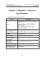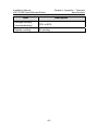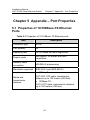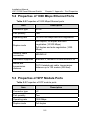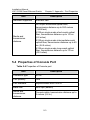
1
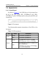
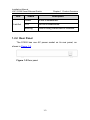
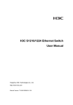
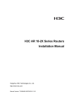
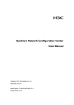
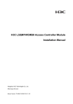
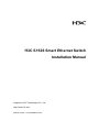
H3C S1526 Smart Ethernet Switch
Installation Manual
Hangzhou H3C Technologies Co., Ltd.
http://www.h3c.com
Manual Version: T2-IM-20080221-3.03
Copyright © 2005-2008, Hangzhou H3C Technologies Co.,
Ltd.
All Rights Reserved
No part of this manual may be reproduced or transmitted in any form
or by any means without prior written consent of Hangzhou H3C
Technologies Co., Ltd.
Trademarks
H3C,
, Aolynk,
, H3Care,
, TOP G,
, IRF,
NetPilot, Neocean, NeoVTL, SecPro, SecPoint, SecEngine, SecPath,
Comware, Secware, Storware, NQA, VVG, V2G, VnG, PSPT, XGbus,
N-Bus, TiGem, InnoVision and HUASAN are trademarks of Hangzhou
H3C Technologies Co., Ltd.
All other trademarks that may be mentioned in this manual are the
property of their respective owners.
CE
This equipment complies with the following European Directives:
89/336/EEC (electromagnetic compatibility), 73/23/EEC (low voltage).
Notice
The information in this document is subject to change without notice.
Every effort has been made in the preparation of this document to
ensure accuracy of the contents, but all statements, information, and
recommendations in this document do not constitute the warranty of
any kind, express or implied.
To obtain the latest information, please access:
http://www.h3c.com
Technical Support
[email protected]
http://www.h3c.com
About This Manual
Purpose
This document is used to guide you through installing this product.
Please read it carefully before your operation.
Intended Audience
This document is intended for network administrators who know well
of the basic network knowledge and network terms.
Organization
This document is organized as follows:
Chapter
Content
1 Product Overview
This chapter describes the appearance of
the H3C S1526 Smart Ethernet Switch
(hereinafter referred to as the S1526).
2 Installation
This chapter describes how to install the
S1526, connect the cables and start up the
S1526.
3 Troubleshooting
This chapter describes solutions for some
common problems.
4
Appendix
Technical
Specifications
–
This chapter describes the technical
specifications of the S1526, such as the
physical
dimensions
and
power
consumption.
Chapter
Content
5 Appendix – Port
Properties
This chapter describes the port properties,
such as the connector type and quantity.
Conventions
The manual uses the following conventions:
I. Symbols
Convention
Description
Caution
Means reader be careful. Improper
operation may cause data loss or damage
to equipment.
Note
Means a complementary description.
Environmental Protection
This product has been designed to comply with the requirements on
environmental protection. For the proper storage, use and disposal of
this product, national laws and regulations must be observed.
Installation Manual
H3C S1526 Smart Ethernet Switch
Table of Contents
Table of Contents
Chapter 1 Product Overview ........................................................1-1
1.1 Introduction ........................................................................1-1
1.2 Appearance........................................................................1-2
1.2.1 Front Panel ..............................................................1-2
1.2.2 Rear Panel...............................................................1-3
Chapter 2 Installation ....................................................................2-1
2.1 Precautions ........................................................................2-1
2.2 Installing the Switch ...........................................................2-3
2.2.1 Installing the Switch into a 19-Inch Rack ................2-3
2.2.2 Installing the Switch on a Workbench .....................2-5
2.3 Connecting the Cables.......................................................2-6
2.3.1 Connecting Devices to the Switch...........................2-6
2.3.2 Connecting the Console Cable................................2-7
2.3.3 Connecting the Power Cable...................................2-8
2.4 Starting Up the Switch .......................................................2-9
2.4.1 Configuring Terminal Parameters ...........................2-9
2.4.2 Starting Up...............................................................2-9
2.4.3 Web Configuration.................................................2-11
Chapter 3 Troubleshooting...........................................................3-1
3.1 Password Loss...................................................................3-1
3.2 Power System Failure........................................................3-1
3.3 Configuration System Failure.............................................3-1
i
Installation Manual
H3C S1526 Smart Ethernet Switch
Table of Contents
Chapter 4 Appendix – Technical Specifications ........................4-1
Chapter 5 Appendix – Port Properties.........................................5-1
5.1 Properties of 10/100Base-TX Ethernet Ports ....................5-1
5.2 Properties of 1000 Mbps Ethernet Ports............................5-2
5.3 Properties of SFP Module Ports ........................................5-2
5.4 Properties of Console Port.................................................5-3
ii
Installation Manual
H3C S1526 Smart Ethernet Switch
Chapter 1 Product Overview
Chapter 1 Product Overview
1.1 Introduction
H3C S1526 Smart Ethernet Switch (hereinafter referred to as
the S1526) is suitable for the networking of small and medium-sized
enterprises, and Internet cafe. It provides one console port, 24 ×
10/100Base-TX autosensing Ethernet ports and two 1000 Mbps
uplink combo ports.
Note:
z
Port 25 and port 26 are 1000 Mbps uplink combo ports. Each
combo port supports one 10/100/1000Base-T autosensing
Ethernet port and one 1000 Mbps SFP module port, which,
however, cannot work simultaneously. If both are enabled
simultaneously, the SFP module port, which has a higher priority,
will be active, while the 10/100/1000Base-T port will be inactive.
z
For information about the technical specifications of the S1526,
refer to Chapter 4 “Appendix – Technical Specifications”.
z
For information about the port attributes of the S1526, refer to
Chapter 5 “Appendix – Port Properties”.
1-1
Installation Manual
H3C S1526 Smart Ethernet Switch
Chapter 1 Product Overview
1.2 Appearance
1.2.1 Front Panel
As shown in Figure 1-1, the S1526 has on its front panel from
the left to the right: Power LED, 10/100Base-TX port LEDs,
10/100Base-TX ports, 1000 Mbps uplink combo ports and LEDs, and
Console port.
Figure 1-1 Front panel
The following table presents descriptions of the LEDs on the
front panel.
Table 1-1 LED descriptions
LED
Status
Description
Green
The switch is powered on.
OFF
The switch is powered off.
Power
Green
Speed
OFF
100 Mbps port: A link in 100 Mbps.
1000 Mbps port: A link in 1000 Mbps.
100 Mbps port: A link in 10 Mbps or no
link is established.
1000 Mbps port: A link in 10/100 Mbps
or no link is established.
1-2
Installation Manual
H3C S1526 Smart Ethernet Switch
LED
Link/Act
Chapter 1 Product Overview
Status
Description
Green
A link is established.
OFF
No link is established.
Blinking
Data is being transmitted or received.
1.2.2 Rear Panel
The S1526 has one AC power socket on its rear panel, as
shown in Figure 1-2.
Figure 1-2 Rear panel
1-3
Installation Manual
H3C S1526 Smart Ethernet Switch
Chapter 2 Installation
Chapter 2 Installation
2.1 Precautions
To avoid any damage to the device or human body arising from
improper use of the S1526, please follow the precautions and
requirements listed below.
I. Safety precautions
z
Unplug the switch before cleaning. Do not clean the switch
with wet cloth or liquid.
z
Do not place the switch near water or in any damp area.
Keep water or moisture from entering the switch chassis.
z
Make sure the switch operates in a clean environment.
Dust buildup on the chassis may result in static absorption,
which will shorten the life span of the switch and cause
communication failure.
z
Keep the switch in good ventilation condition and do not
place one switch on another, because the S1526 adopts
air cooling approach as it generates a small amount of
heat.
z
Make sure that the operating voltage is consistent with that
labeled on the switch, because the switch operates
normally only under proper voltage input.
z
Do not look directly at the laser beam inside the optical
fiber, because it may hurt your eyes.
2-1
Installation Manual
H3C S1526 Smart Ethernet Switch
z
Chapter 2 Installation
Do not open the chassis while the switch is in operation. Do
not open the chassis if not necessary, even when the
switch is not powered on.
II. Installation Environment Requirements
The S1526 can be installed in a corridor or a room. The
following requirements must be met wherever it is installed in a rack
or on a workbench.
z
There is adequate space (more than 10 cm (0.33 in.)) near
the ventilation hole of the switch for heat dissipation of the
switch.
z
The rack or the workbench has an effective cooling
system.
z
The rack or the workbench is sturdy enough to hold the
switch and its accessories.
z
The rack or the workbench is well grounded.
III. Electromagnetic Environment Requirements
In operation the switch may be affected by external
interferences in the form of radiation or conduction. Make sure that:
z
The AC power supply unit is a TN system and the AC
power socket uses a three-terminal, single-phase power
socket with Protection Earth (PE), so that the interference
from the power supply system can be effectively filtered by
the filter circuit in the device.
z
The switch is kept far away from high-power radio
launchers, radar launchers, and any equipment with
high-frequency and high-current.
2-2
Installation Manual
H3C S1526 Smart Ethernet Switch
z
Chapter 2 Installation
Electromagnetic shielding approach is adopted when
necessary, such as using shielded port cable.
z
All port cables are wired indoor, to prevent the ports from
any damage that may be caused by overvoltage and
overcurrent from lightning strike.
2.2 Installing the Switch
Caution:
There is a seal on one mounting screw on the chassis of the switch.
This seal must remain intact unless the agent is on the spot to
maintain your switch. Please contact your local agent and get
permission if you need to open the chassis. Otherwise, you will have
to bear the responsibilities for all the serious consequences arising
therefrom.
2.2.1 Installing the Switch into a 19-Inch Rack
Follow the steps below to mount the switch in a 19-inch
standard rack.
1)
Check that the rack is sturdy and properly earthed.
2)
Use the screws to fix the mounting ears to both sides of the
front panel of the switch.
2-3
Installation Manual
H3C S1526 Smart Ethernet Switch
Chapter 2 Installation
Figure 2-1 Fix the mounting ears
3)
Put the switch in a rack tray. Slide the switch along the
guide rails to an appropriate place.
4)
Fix the mounting ears to the rack posts with screws at both
sides. Make sure the switch is securely fixed to the rack
tray.
Figure 2-2 Installing the switch in a rack
2-4
Installation Manual
H3C S1526 Smart Ethernet Switch
Chapter 2 Installation
Note:
The mounting brackets are used for fixing rather than weight bearing.
In a 19-inch standard rack, the weight of the switch is supported by
the tray beneath it.
2.2.2 Installing the Switch on a Workbench
In circumstances that a 19-inch standard rack is not available,
you can mount the switch on a clean workbench. You are
recommended to fasten the feet to the switch before installation.
Take the following steps to fasten the feet:
1)
Remove the sticker on the feet accompanied with the
device.
2)
Stick the feet to the round recesses on the bottom of the
device.
Figure 2-3 Fastening the feet to the switch
2-5
Installation Manual
H3C S1526 Smart Ethernet Switch
Chapter 2 Installation
2.3 Connecting the Cables
2.3.1 Connecting Devices to the Switch
I. Connect the device to the Ethernet port
Use either crossover cables or straight through cables to
connect the PC(s) or other device(s) to the Ethernet ports on the
switch.
II. Connect the device to the uplink port
z
If the 10/100/1000Base-T Ethernet port is to be used as the
uplink port, connect the device to it with either a crossover
cable or a straight through cable.
z
If the SFP module port is to be used as the uplink port,
connect the SFP module to it firstly, and then connect the
LC connector of the optical fiber to the SFP module, as
shown in the following figure.
Figure 2-4 Connecting to the SFP module port
2-6
Installation Manual
H3C S1526 Smart Ethernet Switch
Chapter 2 Installation
Caution:
To avoid eye damages, do not look directly at the laser beam inside
the optical fiber.
2.3.2 Connecting the Console Cable
Figure 2-5 Connecting the switch to a terminal through console
port
The switch can be configured through a terminal. Take the
following steps to connect the switch and terminal through a console
cable.
1)
Plug the DB-9 connector of the console cable into the serial
port of the PC through which the switch is to be configured.
2)
Plug the RJ-45 connector of the console cable into the
console port of the switch.
2-7
Installation Manual
H3C S1526 Smart Ethernet Switch
Chapter 2 Installation
Caution:
Because the PC serial port is not hot-swappable, DO NOT plug the
cable connector into or unplug it from the PC serial port when the
switch is powered on. In connecting the PC to the switch plug the
DB-9 connector of the console cable to the PC port first, and then
plug the RJ-45 connector to the switch port. In disconnecting unplug
the RJ-45 connector first and then the DB-9 connector.
2.3.3 Connecting the Power Cable
1)
Check if the required power supply unit is used.
2)
Insert one end of the power cable to the socket of the
switch and the other end to the socket of the external
power supply.
Figure 2-6 Connecting the power cable
3)
Check the status of the power LED on the switch. ON
means the connection is OK.
2-8
Installation Manual
H3C S1526 Smart Ethernet Switch
Chapter 2 Installation
2.4 Starting Up the Switch
2.4.1 Configuring Terminal Parameters
1)
Start the PC. In the Windows operating system, click
[Start/Programs/Accessories/Communications] to run the
Hyper Terminal program on the PC.
2)
Set the serial port parameters, as follows (taking the Hyper
z
Bits per second (baud rate): 9600 bps
z
Data bits: 8
z
Stop bits: 1
z
Parity: None
z
Flow control: None
z
Terminal type: VT100 or auto detect
Terminal in Windows XP for example):
Note:
For detailed information about terminal parameter configuration,
refer to H3C S1526 Smart Ethernet Switch User Manual.
2.4.2 Starting Up
After the switch is powered on, press any key so that the switch
starts self test and the self test information is displayed on the
terminal. The message “Press any key to enter main menu” appears
when the self test completes. Press any key to enter the main menu,
which is as follows:
2-9
Installation Manual
H3C S1526 Smart Ethernet Switch
MAIN
Chapter 2 Installation
MENU
1. Modify password
2. Set IP address/Subnet mask/Gateway
3. Reset to default configuration
4. Save current configuration
5. Modify management VLAN
0. Reboot
Enter your choice (0-5):
Select one option and enter its number after the “Enter your
choice (0-5):” to perform the configuration.
Table 2-1 Menu item description
No.
Description
1
Modify the Web NMS password for the switch
2
Set the IP address, subnet mask and gateway for the
switch
3
Restore the switch to factory default settings
4
Save the current configuration
5
Configure the management VLAN
0
Reboot the switch
2-10
Installation Manual
H3C S1526 Smart Ethernet Switch
Chapter 2 Installation
Note:
For detailed information about the configuration commands, refer to
H3C S1526 Smart Ethernet Switch User Manual.
2.4.3 Web Configuration
The Web NMS (Network Management System) feature allows
the user to manage and maintain the S1526 in a very simple and
direct way through Web configuration.
Open the Web browser and input the default IP address of the
switch http://192.168.0.234 in the address bar. Press Enter and a
login dialog box (shown in Figure 2-7) appears, prompting for a user
name and password. For the first time login, input the default user
name: admin, and password: admin. Click <OK> or press Enter to
enter the Web NMS home page.
Figure 2-7 Web NMS login dialog box
2-11
Installation Manual
H3C S1526 Smart Ethernet Switch
Chapter 2 Installation
Note:
For detailed information about the Web configuration, refer to H3C
S1526 Smart Ethernet Switch User Manual.
Caution:
In performing local configuration always set the IP addresses for the
PC and the switch in the same subnet (refer to H3C S1526 Smart
Ethernet Switch
User Manual for the address configuration); in
performing remote configuration make sure that the switch is
reachable to the PC. Otherwise you will not be able to log in the Web
configuration page.
2-12
Installation Manual
H3C S1526 Smart Ethernet Switch
Chapter 3 Troubleshooting
Chapter 3 Troubleshooting
3.1 Password Loss
If you lose your password for the switch, restore the switch to
the factory settings at first by referring to H3C S1526 Smart Ethernet
Switch User Manual. Then you can use the default user name
“admin” and password “admin” to log in.
3.2 Power System Failure
You can know whether or not the power system is working
normally by reading the PWR LED on the front panel. The PWR LED
should be solid ON when the power system is in normal operation. If
not, check that:
z
The switch power cable is correctly connected.
z
The power supply meets the requirement of the switch.
3.3 Configuration System Failure
After powered up, if the switch is operating properly, the start-up
information is displayed on the console terminal. If the configuration
system fails, the terminal displays garbled characters or nothing at
all.
I. No information on the terminal
If the switch is powered up and there is no information on the
console terminal, check the following in order:
z
The power supply is working normally.
z
The console cable is correctly connected.
3-1
Installation Manual
H3C S1526 Smart Ethernet Switch
z
Chapter 3 Troubleshooting
The console cable is in good condition and the terminal
(HyperTerminal for example) parameter settings are
correct. Refer to section 2.4.1
“Configuring Terminal
Parameters” for information about terminal parameter
settings.
II. Garbled characters on the terminal
Make sure you have set on your terminal the following
parameters correctly (HyperTerminal):
z
Bits per second = 9600
z
Data bits = 8
z
Parity = None
z
Stop bits = 1
z
Flow control = None
z
Terminal emulation = VT100 or Auto detect
Reconfigure the parameters if their values are different from the
above.
3-2
Installation Manual
H3C S1526 Smart Ethernet Switch
Chapter 4 Appendix – Technical
Specifications
Chapter 4 Appendix – Technical
Specifications
Table 4-1 Technical specifications
Item
Description
24 autosensing 10/100Base-TX Ethernet
ports
Port
Two autosensing 10/100/1000Base-T
Ethernet ports
Two 1000 Mbps SFP module ports
One Console port
Physical dimensions
(H × W × D)
44 × 440 × 230 mm (1.7 ×17.3 × 9.1 in.)
Weight
2.7 kg (6.0 lb.)
Input voltage
100 VAC to 240 VAC, 50/60 Hz
Maximum power
consumption
15 W
Operating
temperature
0°C to 40°C (32°F to 104°F)
Storage temperature
–10°C to +70°C (14°F to 158°F)
Operating humidity
(noncondensing)
20% to 85%
4-1
Installation Manual
H3C S1526 Smart Ethernet Switch
Chapter 4 Appendix – Technical
Specifications
Item
Description
Storage humidity
(noncondensing)
10% to 90%
System cooling
Air cooling
4-2
Installation Manual
H3C S1526 Smart Ethernet Switch
Chapter 5 Appendix – Port Properties
Chapter 5 Appendix – Port Properties
5.1 Properties of 10/100Base-TX Ethernet
Ports
Table 5-1 Properties of 10/100Base-TX Ethernet ports
Item
Description
Connector type
RJ-45
Port quantity
24
Operating rate
10/100 Mbps and auto negotiation
Duplex mode
Half duplex, full duplex and auto
negotiation
Network cable
connection
MDI/MDI-X autosensing
Standards supported
IEEE 802.3 and IEEE 802.3u
z
Media and
transmission
distance
10Base-T:
CAT-3/4/5 UTP cable, transmission
distance up to 100 meters (328 feet)
z
100Base-TX:
CAT-5 UTP cable, transmission distance
up to 100 meters (328 feet)
5-1
Installation Manual
H3C S1526 Smart Ethernet Switch
Chapter 5 Appendix – Port Properties
5.2 Properties of 1000 Mbps Ethernet Ports
Table 5-2 Properties of 1000 Mbps Ethernet ports
Item
Description
Connector type
RJ-45
Port quantity
Two
Operating rate
10/100/1000 Mbps and Auto negotiation
Duplex mode
Half duplex, full duplex and auto
negotiation (10/100 Mbps)
Full duplex and auto negotiation (1000
Mbps)
Network cable
connection
MDI/MDI-X
Standards supported
IEEE802.3, IEEE802.3u and IEEE802.3z
Media and
transmission
distance
CAT-5 twisted pair cable, transmission
distance up to 100 meters (328 feet)
5.3 Properties of SFP Module Ports
Table 5-3 Properties of SFP module ports
Item
Description
Connector type
LC
Port quantity
Two
Operating rate
1000 Mbps
Duplex mode
Full duplex
5-2
Installation Manual
H3C S1526 Smart Ethernet Switch
Chapter 5 Appendix – Port Properties
Item
Standard supported
Description
IEEE802.3ab
50/125µm multimode optical fiber,
transmission distance up to 550 meters
(1,804 feet)
Media and
transmission
distance
9/125µm single-mode short-reach optical
fiber, transmission distance up to 10 km
(6.2 miles)
9/125µm single-mode intermediate-reach
optical fiber, transmission distance up to 40
km (24.9 miles)
9/125µm single-mode long-reach optical
fiber, transmission distance up to 70 km
(43.5 miles)
5.4 Properties of Console Port
Table 5-4 Properties of Console port
Item
Description
Connector type
RJ-45
Port quantity
One
Port standard
Asynchronous EIA/TIA-232
Baud rate
9600 bps (default)
Media and
transmission
distance
Console cable, transmission distance up to
2 meters (6.6 in.)
5-3