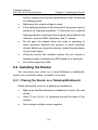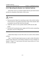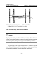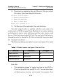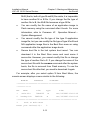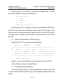
1
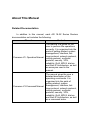
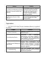
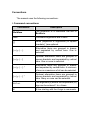
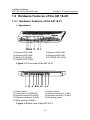
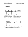
H3C AR 18-2X Series Routers
Installation Manual
Hangzhou H3C Technologies Co., Ltd.
http://www.h3c.com
Manual Version: T2-08045E-20070423-C-1.02
Copyright © 2006-2007, Hangzhou H3C Technologies Co.,
Ltd. and its licensors
All Rights Reserved
No part of this manual may be reproduced or transmitted in any form
or by any means without prior written consent of Hangzhou H3C
Technologies Co., Ltd.
Trademarks
H3C,
, Aolynk,
, H3Care,
, TOP G,
, IRF,
NetPilot, Neocean, NeoVTL, SecPro, SecPoint, SecEngine, SecPath,
Comware, Secware, Storware, NQA, VVG, V2G, VnG, PSPT, XGbus,
N-Bus, TiGem, InnoVision and HUASAN are trademarks of Hangzhou
H3C Technologies Co., Ltd.
All other trademarks that may be mentioned in this manual are the
property of their respective owners.
Notice
The information in this document is subject to change without notice.
Every effort has been made in the preparation of this document to
ensure accuracy of the contents, but all statements, information, and
recommendations in this document do not constitute the warranty of
any kind, express or implied.
To obtain the latest information, please access:
http://www.h3c.com
Technical Support
[email protected]
http://www.h3c.com
About This Manual
Related Documentation
In addition to this manual, each AR 18-2X Series Routers
documentation set includes the following:
Manual
Content
Comware V3 Operation Manual
The manual is a guide for the
user to perform the operations
correctly. It is organized into the
parts of getting started, system
management, interface, link
layer protocol, network protocol,
routing protocol, multicast
protocol, security, VPN,
reliability, QoS, MPLS, dial-up
and Non-IP Architecture, as well
as acronyms used in the
manual.
Comware V3 Command Manual
The manual gives the user a
detailed description of the
operating commands. It is
organized into the parts of
getting started, system
management, interface, link
layer protocol, network protocol,
routing protocol, multicast
protocol, security, VPN,
reliability, QoS, MPLS, dial-up
and Non-IP Architecture, as well
as a command index.
Manual
Content
Low-End and Mid-Range Series
Routers Terminal Access User
Manual
This manual covers all interface
cards and modules available
with H3C AR Series Routers,
including the cable pinouts,
function, interface attribute,
panels and LEDs.
LMR Series Routers Cable
Manual
This manual introduces all cable
pinouts available with LMR
series routers.
Organization
H3C AR 18-2X Series Routers Installation Manual is organized
as follows:
Chapter
Contents
1 Product Overview
Hardware Features of H3C AR 18-2X
Series Routers
2 Installing the Router
Introduces
the
installation
requirements, the issues needed to
be considered and the installation
tools needed for the installation of the
AR 18-2X Series Routers.
3. Starting and Maintaining
the Router
Covers the configuration and
software maintenance of the H3C AR
18-2X Series Routers, including
software upgrade and the application
program upgrade.
4. Troubleshooting
Lists the problems and checkup
methods when H3C AR 18-2X Series
Routers are installed.
Conventions
The manual uses the following conventions:
I. Command conventions
Convention
Description
Boldface
The keywords of a command line are in
Boldface.
italic
Command arguments are in italic.
[]
Items (keywords or arguments) in square
brackets [ ] are optional.
{ x | y | ... }
Alternative items are grouped in braces
and separated by vertical bars. One is
selected.
[ x | y | ... ]
Optional alternative items are grouped in
square brackets and separated by vertical
bars. One or none is selected.
{ x | y | ... } *
Alternative items are grouped in braces
and separated by vertical bars. A minimum
of one or a maximum of all can be selected.
[ x | y | ... ] *
Optional alternative items are grouped in
square brackets and separated by vertical
bars. Many or none can be selected.
&<1-n>
The argument(s) before the ampersand (&)
sign can be entered 1 to n times.
#
A line starting with the # sign is comments.
II. GUI conventions
Convention
Description
<>
Button names are inside angle brackets.
For example, click <OK>.
[]
Window names, menu items, data table
and field names are inside square
brackets. For example, pop up the [New
User] window.
/
Multi-level menus are separated by forward
slashes. For example, [File/Create/Folder].
III. Symbols
Convention
Warning
Caution
Note
Description
Means reader be extremely careful.
Improper operation may cause bodily
injury.
Means reader be careful. Improper
operation may cause data loss or damage
to equipment.
Means a complementary description.
Environmental Protection
This product has been designed to comply with the requirements
on environmental protection. For the proper storage, use and disposal
of this product, national laws and regulations must be observed.
Installation Manual
H3C AR 18-2X Series Routers
Table of Contents
Table of Contents
Chapter 1 Product Overview ........................................................1-1
1.1 Introduction ........................................................................1-1
1.2 Hardware Features of the AR 18-2X..................................1-2
1.2.1 Hardware Features of the AR 18-21 .......................1-2
1.2.2 Hardware Features of the AR 18-22 .......................1-6
1.2.3 Hardware Features of the AR 18-22-8/18-22S-8 ....1-9
1.2.4 Hardware Features of the AR 18-23-1/18-23S-1 ..1-12
i
Installation Manual
H3C AR 18-2X Series Routers
Chapter 1 Product Overview
Chapter 1 Product Overview
1.1 Introduction
H3C AR 18-2X Series Routers (hereinafter referred to as the AR
18-2X series) are Ethernet access routers designed for small office
home office (SOHO) subscribers. By far, the series have six models:
AR 18-21/18-22/18-22-8/18-22S-8/18-23-1/18-23S-1. They provide
an uplink Ethernet interface and four downlink layer 2 (L2) switched
10/100BASE-T Ethernet interfaces that can be isolated.
The AR 18-2X series support multiple virtual private network
(VPN) services, such as layer 2 tunneling protocol (L2TP) VPN, IP
security (IPSec) VPN, generic routing encapsulation (GRE) VPN, and
dynamic VPN (DVPN). They can provide tunnel connections to remote
users to build VPNs that can be internets, intranets, or access
networks.
The series support firewall, AAA (authentication, authorization,
accounting), network address translation (NAT), and quality of service
(QoS). Therefore, they can ensure security and guaranteed services
to the private networks constructed on the open Internet.
In the series the AR 18-22S-8 and AR 18-23S-1 has a build-in
hardware encryption chip, which can significantly improve encryption
performance.
The interfaces that the AR 18-2X series provide are compliant
with the international standards and can work with the products of
other vendors at every layer. The existing investment of users can
thus be protected to the maximum.
1-1
Installation Manual
H3C AR 18-2X Series Routers
Chapter 1 Product Overview
1.2 Hardware Features of the AR 18-2X
1.2.1 Hardware Features of the AR 18-21
I. Appearance
1) Ethernet LED LAN4
3) Ethernet LED LAN2
5) WAN LED (WAN0)
7) POWER LED (PWR)
2) Ethernet LED LAN3
4) Ethernet LED LAN1
6) SYSTEM LED (SYS)
Figure 1-1 Front view of the AR 18-21
1) Power switch
3) Console port (CONSOLE)
5) Ethernet interface 2(LAN2)
7) Ethernet interface 4 (LAN4)
9) WAN interface (WAN0)
2) Power socket
4) Ethernet interface 1 (LAN1)
6) Ethernet interface 3 (LAN3)
8) Grounding screw
Figure 1-2 Rear view of the AR 18-21
1-2
Installation Manual
H3C AR 18-2X Series Routers
Chapter 1 Product Overview
II. System specifications
Table 1-1 System specifications of the AR 18-21
Item
AR 18-21
1 console port
Interface
1 x 10/100 Mbps Ethernet interface (WAN)
4 x 10/100 Mbps Ethernet interfaces (LAN)
Processor
MPC8247
SDRAM
64 MB
Flash
8 MB
Hardware
encryption
––
Max. power
10 W
Power
supply
(extern
al)
Input
Output
Dimensions (W x
D x H)
Rated voltage: 100 to 240 VAC; 50 to 60 Hz
Current: 0.5 A
Voltage: 12 VDC
Current: 1.25 A
300 x 180 x 45 mm (11.81 x 7.09 x 1.77 in.)
(the maximum measurements, including the
bulge)
Weight
1kg (2.20 lb)
Operating
temperature
0 to 40 C (32 to 104 F)
Relative humidity
(non-condensing)
5 to 90%
1-3
Installation Manual
H3C AR 18-2X Series Routers
Chapter 1 Product Overview
III. LEDs
You can gather information about the status of the AR 18-21 and
its interfaces by reading the seven LEDs on its cover, as shown below.
Table 1-2 LEDs on the cover of the AR 18-21
LED
LAN1/LAN2/
LAN3/LAN4/
WAN0
Description
OFF means no link is present.
ON means a link is present.
Blinking means data is being sent or/and received.
Blinking means the system is operating normally.
SYS
Steady ON or OFF means the system is improperly
operating.
OFF means no power is being supplied.
PWR
ON means power is being supplied.
IV. Interface attributes
The interfaces that the AR 18-21 provides are described as
follows:
1)
Console port
Table 1-3 Attributes of the console port
Attribute
Description
Connector
RJ45
Interface standard
Asynchronous RS232
Baud rate
9600 (default) to 115200 bps
1-4
Installation Manual
H3C AR 18-2X Series Routers
Chapter 1 Product Overview
Attribute
Description
Connection to an ASCII terminal
Connection to the serial interface on a PC to
run the terminal emulation program on the PC
Service
Command line interface (CLI)
2)
Ethernet interface
Table 1-4 Attributes of the Ethernet interface
Attribute
10BASE-T
10/100BASE-T
Connector
RJ45
Interface type
MDI/MDIX autosensing
Operating
mode
10 Mbps
10/100 Mbps autosensing
Full duplex/half
duplex
Full duplex/half duplex
1-5
Supports only L2 switching
Installation Manual
H3C AR 18-2X Series Routers
Chapter 1 Product Overview
1.2.2 Hardware Features of the AR 18-22
I. Appearance
1) Ethernet LED LAN4
3) Ethernet LED LAN2
5) WAN LED (WAN1)
7) SYSTEM LED (SYS)
2) Ethernet LED LAN3
4) Ethernet LED LAN1
6) WAN LED (WAN0)
8) POWER LED (PWR)
Figure 1-3 Front view of the AR 18-22
1) Power switch
3) Console port (CONSOLE)
5) Ethernet interface 2(LAN2)
7) Ethernet interface 4 (LAN4)
9) WAN interface (WAN0)
2) Power socket
4) Ethernet interface 1 (LAN1)
6) Ethernet interface 3 (LAN3)
8) Grounding screw
10) WAN interface (WAN1)
Figure 1-4 Rear view of the AR 18-22
1-6
Installation Manual
H3C AR 18-2X Series Routers
Chapter 1 Product Overview
II. System specifications
Table 1-5 System specifications of the AR 18-22
Item
AR 18-22
1 console port
Interface
2 x 10/100 Mbps Ethernet interface (WAN)
4 x 10/100 Mbps Ethernet interfaces (LAN)
Processor
MPC8247
SDRAM
64 MB
Flash
8 MB
Hardware
encryption
––
Max. power
10 W
Power
supply
(extern
al)
Input
Output
Dimensions (W x
D x H)
Rated voltage: 100 to 240 VAC; 50 to 60 Hz
Current: 0.5 A
Voltage: 12 VDC
Current: 1.25 A
300 x 180 x 45 mm (11.81 x 7.09 x 1.77 in.)
(the maximum measurements, including the
bulge)
Weight
1kg (2.20 lb)
Operating
temperature
0 to 40 C (32 to 104 F)
Relative humidity
(non-condensing)
5 to 90%
1-7
Installation Manual
H3C AR 18-2X Series Routers
Chapter 1 Product Overview
III. LEDs
You can gather information about the status of the AR 18-22 and
its interfaces by reading the eight LEDs on its cover, as shown below.
Table 1-6 LEDs on the cover of the AR 18-22
LED
Description
OFF means no link is present.
LAN1/LAN2/L
AN3/LAN4/W
AN0/WAN1
ON means a link is present.
Blinking means data is being sent or/and
received.
Blinking means the system is operating normally.
SYS
PWR
Steady ON or OFF means the system is
improperly operating.
OFF means no power is being supplied.
ON means power is being supplied.
IV. Interface attributes
The AR 18-22 provides a consol port and 10/100 Mbps Ethernet
interfaces. Refer to 1.2.1 IV. for attributes detail.
The WAN1 interface supports only MDI other than MDI/MDIX
autosensing. Other Ethernet interfaces share the same attributes with
the AR 18-21.
1-8
Installation Manual
H3C AR 18-2X Series Routers
Chapter 1 Product Overview
1.2.3 Hardware Features of the AR 18-22-8/18-22S-8
I. Appearance
1) POWER LED (PWR)
2) Connection LEDS of Ethernet Interfaces LAN1-LAN8 (LINK/ACT)
3) Reset
4) Console Port
5) WAN Port (WAN1)
6)WAN Port (WAN0)
7) Speed LEDs of Ethernet Interfaces LAN1-LAN8 (SPEED)
8) Layer2 Ethernet Interfaces LAN1-LAN8
9) SYSTEM LED (SYS)
Figure 1-5 Front view of the AR 18-22-8/18-22S-8
1) Grounding screw
2) Power socket
3) Power switch
Figure 1-6 Rear view of the AR 18-22-8/18-22S-8
1-9
Installation Manual
H3C AR 18-2X Series Routers
Chapter 1 Product Overview
II. System specifications
Table 1-7 System specifications of the AR 18-22-8/18-22S-8
Item
AR 18-22-8
AR 18-22S-8
1 console port
Interface
2 x 10/100 Mbps Ethernet interface (WAN)
8 x 10/100 Mbps Ethernet interfaces (LAN)
Processor
MPC8248
SDRAM
64 MB
128 MB
Flash
8 MB
16 MB
Hardware encryption
––
Supported
Max. power
10 W
Input
voltage and
current
Rated voltage: 100 to 240 VAC; 50 to 60
Hz
AC
Dimensions (W x D x
H)
Current: 0.5 -1 A
300 x 225 x 42 mm (11.81 x 8.85 x 1.65 in.)
(the maximum measurements, including
the bulge)
Weight
2kg (4.40 lb)
Operating
temperature
0 to 40 C (32 to 104 F)
Relative humidity
(non-condensing)
5 to 90%
1-10
Installation Manual
H3C AR 18-2X Series Routers
Chapter 1 Product Overview
III. LEDs
You can gather information about the status of the AR
18-22-8/18-22S-8 and its interfaces by reading the twenty-two LEDs
on its cover, as shown below. Every LAN/WAN interface has LEDs
LINK/ACT and SPEED to indicate its running state.
Table 1-8 LEDs on the cover of the AR 18-22-8/18-22S-8
LED
Description
OFF means no link is present.
LAN1/LAN
2/LAN3/LA
N4/LAN5/L
AN6/LAN7
LAN8/WA
N0/WAN1
SYS
PWR
LINK/ACT
ON means a link is present.
Blinking means data is being sent
or/and received.
SPEED
OFF means the link rate is 10 Mbps.
ON means the link rate is 100 Mbps.
Blinking means the system is operating
normally.
Steady ON or OFF means the system is
improperly operating.
OFF means no power is being supplied.
ON means power is being supplied.
IV. Interface attributes
The AR 18-22-8/18-22S-8 provides a consol port and 10/100
Mbps Ethernet interfaces. Refer to 1.2.1 IV. for attributes detail.
The WAN1 interface supports only MDI other than MDI/MDIX
autosensing. Other Ethernet interfaces share the same attributes with
the AR 18-21.
1-11
Installation Manual
H3C AR 18-2X Series Routers
Chapter 1 Product Overview
1.2.4 Hardware Features of the AR 18-23-1/18-23S-1
I. Appearance
1) POWER LED (PWR)
3) Console Port (CONSOLE)
5) Ethernet Interface ETH1
7) Ethernet Interface ETH3
2) Reset
4) Ethernet Interface ETH0
6) Ethernet Interface ETH2
8) SYSTEM LED (SYS)
Figure 1-7 Front view of the AR 18-23-1/18-23S-1
1) Grounding screw
2) Power socket
3) Power switch
Figure 1-8 Rear view of the AR 18-23-1/18-23S-1
1-12
Installation Manual
H3C AR 18-2X Series Routers
Chapter 1 Product Overview
II. System specifications
Table 1-9 System specifications of the AR 18-23-1/18-23S-1
Item
AR 18-23-1
AR 18-23S-1
1 console port
Interface
4 x 10/100 Mbps Ethernet interface
Processor
MPC8248
SDRAM
64 MB
128 MB
Flash
8 MB
16 MB
Hardware
encryption
––
Supported
Max. power
10 W
Input
voltage and
current
AC
Dimensions (W x D
x H)
Rated voltage: 100 to 240 VAC; 50 to 60 Hz
Current: 0.5 -1 A
300 x 225 x 42 mm (11.81 x 8.85 x 1.65 in.)
(the maximum measurements, including the
bulge)
Weight
2kg (4.40 lb)
Operating
temperature
0 to 40 C (32 to 104 F)
Relative humidity
(non-condensing)
5 to 90%
1-13
Installation Manual
H3C AR 18-2X Series Routers
Chapter 1 Product Overview
III. LEDs
You can gather information about the status of the AR
18-23-1/18-23S-1 and its interfaces by reading the ten LEDs on its
cover, as shown below.
Table 1-10 LEDs on the cover of the AR 18-23-1/18-23S-1
LED
Description
OFF means no link is present.
ETH0/
ETH1/
ETH2/
ETH3
LINK/ACT
Blinking means data is being sent or/and
received.
SPEED
SYS
PWR
ON means a link is present.
OFF means the link rate is 10 Mbps.
ON means the link rate is 100 Mbps.
Blinking means the system is operating
normally.
Steady ON or OFF means the system is
improperly operating.
OFF means no power is being supplied.
ON means power is being supplied.
IV. Interface attributes
The AR 18-23-1/18-23S-1 provides a consol port and 10/100
Mbps Ethernet interfaces. Refer to 1.2.1 IV. for attributes detail.
The ETHO/ETH1 interface supports only MDI other than
MDI/MDIX autosensing. Other Ethernet interfaces share the same
attributes with the AR 18-21.
1-14
Installation Manual
H3C AR 18-2X Series Routers
Table of Contents
Table of Contents
Chapter 2 Installing the Router ....................................................2-1
2.1 Safety Precautions .............................................................2-1
2.2 Installing the Router ...........................................................2-2
2.2.1 Placing the Router on a Tabletop/Workbench ........2-2
2.2.2 Mounting the Router on a Vertical Surface .............2-3
2.2.3 Installing the Router in a Rack ................................2-4
2.3 Connecting the Ground Wire .............................................2-5
2.4 Connecting the Power Cord...............................................2-6
2.5 Connecting the Router to a Console Terminal...................2-7
2.6 Connecting the Router to LAN ...........................................2-8
2.7 Verifying Installation ...........................................................2-9
i
Installation Manual
H3C AR 18-2X Series Routers
Chapter 2 Installing the Router
Chapter 2 Installing the Router
2.1 Safety Precautions
Caution:
Observe the safety precautions in this section when installing or
maintaining your router to avoid bodily injuries or device impairment
caused by improper actions.
z
Maintain an indoor temperature in the range 0 to 40 C (32 to
104 F) and a humidity level in the range 5 to 90%.
z
Keep the router away from radio transmitting stations, radar
stations, and high-frequency devices. Use electromagnetic
shielding if necessary.
z
Do not put the router on an unstable table or platform.
z
Make sure that the rack/workbench has a good ventilation
system and is properly grounded.
z
Wear an ESD-preventive wrist strap during installation,
making sure that it has good skin-contact.
z
Reserve adequate clearance at the air intake and exhaust
vents for ventilation.
z
For power supply, use a single-phase three-line power
socket with a neutral point or use a universal PC power
2-1
Installation Manual
H3C AR 18-2X Series Routers
Chapter 2 Installing the Router
socket, making sure that the neutral point is well connected
to building ground.
z
Make sure the correct voltage is used.
z
Put a lightning arrester at the front end of the power input to
enhance its lightning protection. To this end, put a special
lightning arrester at the front end of signal cables that are led
outdoors, such as ISDN, telephone, and T1 cables.
z
Do not open the chassis when the router is operating or
when electricity hazards are present to avoid electrical
shocks. Before you open the chassis, obtain the permission
of your sales agent.
z
Correctly connect the interface cables. Do not connect a
telephone cable (including the ISDN cable) to a serial port.
z
Do not hot swap any cable.
2.2 Installing the Router
You can place your router on a sturdy tabletop or workbench,
mount it on a vertical surface, or install it on a rack.
2.2.1 Placing the Router on a Tabletop/Workbench
When placing the router on a tabletop or workbench,
z
Make sure that the tabletop or workbench is clean, flat, and
sturdy.
z
Allow 10 cm (3.9 in.) of clearance around the sides of the
chassis.
z
Do not stack multiple routers together.
2-2
Installation Manual
H3C AR 18-2X Series Routers
Chapter 2 Installing the Router
2.2.2 Mounting the Router on a Vertical Surface
Mount the router on a vertical surface with four pan-head screws
and the four brackets at the bottom of the router.
Caution:
z
Securely anchor these four mounting screws in the vertical surface.
If the screws are not properly anchored, strain of the network cable
connections can pull the router from the wall.
z
Install the router in such a position that the LEDs can be read
easily.
z
Securely fix the external power supply unit of the router, preventing
the power cord from falling down.
Follow these steps to mount the router on a wall or other vertical
surface:
Step 1: Install four pan-head screws on a wall or other flat vertical
surface (with reference to the distance between the four brackets as
shown in Figure 2-1), and ensure that each screw sticks out 6 mm
(0.24 in.) on the wall.
2-3
Installation Manual
H3C AR 18-2X Series Routers
Chapter 2 Installing the Router
Figure 2-1 Chassis bottom
Step 2: Hang the router on the screws by the four brackets.
2.2.3 Installing the Router in a Rack
The AR 18-22-8, AR 18-22S-8, AR 18-23-1, AR 18-23S-1 can be
installed in a 19 inch rack.
The following are Installation steps.
1)
Check the stability and grounding of the rack. Use screws to
install rack-mounting ears on the router’s front or rear cover.
2)
Place the router on a pallet of the rack and slide it to a proper
position. Keep a proper distance between the router and
slides.
3)
Use rustproof pan head screws to fix the rack-mounting ears
to the rack, keeping the router horizontal.
2-4
Installation Manual
H3C AR 18-2X Series Routers
1) Fixing the rack-mounting ears
Chapter 2 Installing the Router
2) Fixing the slides
Figure 2-2 AR 18-2X installation in a rack
2.3 Connecting the Ground Wire
Caution:
Properly connect the ground wire before connecting other cables and
shorten it as much as possible to prevent the router and the connected
device from getting damaged during periods of lightning activities.
The grounding screw of the chassis PGND is located on the rear
panel. Connect this screw to the earth ground using a ground wire.
The grounding resistance must not be greater than 5-ohm.
2-5
Installation Manual
H3C AR 18-2X Series Routers
Chapter 2 Installing the Router
2.4 Connecting the Power Cord
I. AC-input power supply
For the AR 18-2X series, an external AC-input power supply is
provided with these specifications:
Input rated voltage: 100 to 240 VAC, 50 to 60 Hz
Input current: 0.5 to 1A
Output voltage: 12 VDC
Output current: 1.25 A
Figure 2-3 illustrates the power supply:
Figure 2-3 Power supply
II. Connecting the AC-input power cord
Step 1: Put the power switch of the router in OFF position.
Step 2: Connect the output of the power supply to the power input
on the rear panel of the router, and then insert the input connector of
the power supply into an AC power outlet.
Step 3: Put the power switch of the router in ON position.
2-6
Installation Manual
H3C AR 18-2X Series Routers
Chapter 2 Installing the Router
Step 4: Check that the PWR LED on the front panel of the router
is ON. If the LED is OFF, repeat steps 2 through 4.
Caution:
If the PWR LED is still off after you repeat steps 2 through 4 several
times, refer to “Chapter 4 Troubleshooting” for a solution.
2.5 Connecting the Router to a Console
Terminal
I. Console cable
The console cable has an RJ45 connector at one end and a DB9
(female) connector at the other end.
A
A
Figure 2-4 Console cable assembly
II. Connecting the console cable
Follow these steps to connect the router to a console terminal:
Step 1: Select a console terminal.
The console terminal can be either a standard ASCII terminal
with an RS-232 serial interface or more commonly, a PC.
2-7
Installation Manual
H3C AR 18-2X Series Routers
Chapter 2 Installing the Router
Step 2: Connect the console cable.
Power off the router and the console terminal, and then connect
the RS-232 serial port on the console terminal to the console port on
the router using the console cable.
Verify the connection and power on the router. In normal cases,
the startup information is displayed on the terminal screen. For details,
refer to “Chapter 3 Starting and Maintaining the Router”.
2.6 Connecting the Router to LAN
I. Ethernet cable
A 10/100Base-TX Ethernet interface is usually connected to an
Ethernet using a category 5 twisted pair cable, as shown in Figure 2-5:
Figure 2-5 Ethernet cable assembly
Ethernet cables fit into two categories: straight-through and
crossover.
z
Straight-through cable, at both ends of which, the wires are
crimped in the RJ45 connectors in the same sequence. The
cable is used for connecting different types of devices, such
as a terminal device (PC for example) or router to a Hub or
LAN switch.
z
Crossover cable, at both ends of which, the wires are
crimped in the RJ 45 connectors in different sequence. The
2-8
Installation Manual
H3C AR 18-2X Series Routers
Chapter 2 Installing the Router
cable is used for connecting the same type of devices, such
as PC to PC or PC to router.
Caution:
In preparing network cables, shielded cables are preferred for the
sake of electromagnetic compatibility.
II. Connecting an Ethernet cable
Caution:
Read the mark above the port to be connected carefully before making
connection to make sure it is the right port.
The 10/100BASE-T interface on the AR18-2X series supports
MDI/MDIX autosensing. Therefore, you can connect your router to
another device using either straight-through cable or crossover cable
without considering whether the two devices are of the same type.
You can simply connect one end of the network cable to the
Ethernet port on the router and the other end to another device.
2.7 Verifying Installation
After you complete installation, verify that:
2-9
Installation Manual
H3C AR 18-2X Series Routers
Chapter 2 Installing the Router
z
The proper power supply is used.
z
The grounding wire of the router is correctly connected.
z
The console cable and the power cord are correctly
connected.
2-10
Installation Manual
H3C AR 18-2X Series Routers
Table of Contents
Table of Contents
Chapter 3 Starting and Maintaining the Router..........................3-1
3.1 Starting up the Router........................................................3-1
3.1.1 Setting up a Configuration Environment .................3-1
3.1.2 Powering on the Router...........................................3-5
3.2 Maintaining the Router.......................................................3-6
3.2.1 Boot Menu (8 MB Flash Is Installed) .......................3-6
3.2.2 Boot Menu (16 MB Flash Is Installed) ...................3-10
3.2.3 Upgrading Programs through XModem.................3-16
3.2.4 Backing up and Restoring the Extended Segment of
the Boot Rom Program...................................................3-20
3.2.5 Upgrading Boot ROM at CLI .................................3-21
3.2.6 Upgrading Application Programs with NET...........3-25
i
Installation Manual
H3C AR 18-2X Series Routers
Chapter 3 Starting and Maintaining
the Router
Chapter 3 Starting and Maintaining the
Router
3.1 Starting up the Router
3.1.1 Setting up a Configuration Environment
I. Connecting the router to a console terminal
To set up a local configuration environment, simply connect the
RJ45 connector of the console cable to the console port on the router,
and the DB9 connector to the serial port on the console terminal, a PC
for example, as shown in Figure 3-1.
PC
Router
Console cable
Console port
Figure 3-1 Local configuration through the console port
II. Setting terminal parameters
Follow these steps to set terminal parameters on the console
terminal, a PC that runs Windows98 for example:
Step 1: Start the PC and select [Start/Programs/Accessories/
Communications/ HyperTerminal].
3-1
Installation Manual
H3C AR 18-2X Series Routers
Chapter 3 Starting and Maintaining
the Router
The HyperTerminal window displays the Connection Description
dialog box, as shown in Figure 3-2.
Figure 3-2 Setting up a new connection
Step 2: Enter the name of the new connection in the Name field
and click <OK>. The dialog box, as shown in Figure 3-3, displays.
Step 3: Select the serial port to be used from the Connect Using
dropdown menu. The serial port must be the same port connected by
the console cable.
3-2
Installation Manual
H3C AR 18-2X Series Routers
Chapter 3 Starting and Maintaining
the Router
Figure 3-3 Setting the connection port
Step 4: Click <OK>. The Port Settings tab, shown in Figure 3-4,
appears and you can set serial port parameters. Set the following
parameters:
Baud rate = 9600
Databit = 8
Parity check = none
Stopbit = 1
Flow control = none
3-3
Installation Manual
H3C AR 18-2X Series Routers
Chapter 3 Starting and Maintaining
the Router
Figure 3-4 Setting communications parameters
Step 6: Click <OK>. The HyperTerminal dialogue box appears.
Step 7: Select Properties.
Step 8: In the Properties dialog box, select the Settings tab, as
shown in Figure 3-5.
Step 9: Select VT100 or Auto detect in the Emulation dropdown
menu.
Step 10: Click <OK>.
3-4
Installation Manual
H3C AR 18-2X Series Routers
Chapter 3 Starting and Maintaining
the Router
Figure 3-5 Setting the terminal type
3.1.2 Powering on the Router
After the router is powered on, the Boot Rom program runs first
and the following system information appears on the terminal screen:
System starts booting...(V10.50)
**************************************************
*
*
3-5
Installation Manual
H3C AR 18-2X Series Routers
*
Chapter 3 Starting and Maintaining
the Router
H3C Series Routers Boot Rom V15.00
*
*
*
**************************************************
Copyright(c) 2004-2006 Hangzhou H3C Tech. Co., Ltd.
Compiled at Tue Mar 28 14:58:33 CST 2006
Testing memory...OK!
256M bytes DDR SDRAM Memory
16M
bytes Flash Memory
Hardware Version is 4.0
CPLD
Version is 1.0
Press Ctrl-B to enter Boot Menu
Press <Enter>. The system displays (if login authentication is not
enabled):
<H3C>
This prompt indicates that the router enters system view, and is
ready for configuration.
3.2 Maintaining the Router
3.2.1 Boot Menu (8 MB Flash Is Installed)
The AR 18-21/18-22/18-22-8/18-23-1 has an 8MB flash.
Start the router. When the information “Press Ctrl-B to enter Boot
Menu” appears on the terminal screen, press <Ctrl+B>. The system
displays:
3-6
Installation Manual
H3C AR 18-2X Series Routers
Please
Chapter 3 Starting and Maintaining
the Router
input Boot Rom password :
Caution:
z
Press <Ctrl+B> within three seconds after the prompt “Press Ctrl-B
to Enter Boot Menu...?” appears to enter the Boot Menu. Otherwise,
the system starts decompressing the program.
z
If you want to enter the Boot menu after the system starts
decompressing the program, you need to reboot the router.
Type the correct password and press <Enter>. (If no Boot Rom
password is configured, just press <Enter>.) The system accesses the
following Boot menu:
Boot Menu:
1:
Download application program with XMODEM
2:
Download application program with NET
3:
Start up and ignore configuration
4:
Enter debugging environment
5:
Boot Rom Operation Menu
6:
Do not check the version of the software
7:
Exit and reboot
Enter your choice(1-7):
Note that:
1)
To download an application program through XModem, see
3.2.3 Upgrading Programs through XModem.
3-7
Installation Manual
H3C AR 18-2X Series Routers
2)
Chapter 3 Starting and Maintaining
the Router
To download an application program through Ethernet,
select <2>. This menu appears:
Net Port Download Menu:
1:
Change Net Parameter
2:
Download From Net
3:
Exit to Main Menu
Enter your choice(1-3):1
z
Select <1> to change the parameters for downloading. The
following information is displayed:
Change Boot Parameter:
'.' = clear field;
'-' = go to previous field;
boot device
: mot fccl
processor number
: 0
host name
: 8040
file name
: M8240ram.arj
inet on ethernet (e) : 169.254.10.10
inet on backplane (b):
host inet (h)
: 169.254.10.11
gateway inet (g)
:
user (u)
: 8040
ftp password (pw) (blank = use rsh):
flags (f)
: 0x0
target name (tn)
:
startup script (s)
:
other (o)
:
3-8
^D = quit
Installation Manual
H3C AR 18-2X Series Routers
Chapter 3 Starting and Maintaining
the Router
Note:
You can change the parameter settings behind the colons (:). The
“boot device” field is “motfcc1” for AR 18-2X routers.
The AR 18-2X allows you to download programs through both
TFTP and FTP. For the procedures, see the section 3.2.5 "Upgrading
Boot ROM at CLI".
After you set the parameters, select <2> to start
z
downloading.
z
Select <3> to exit to the main menu.
3)
Start up and ignore the configuration file.
4)
Enter debugging environment for troubleshooting.
Caution:
Upgrade router software only when necessary and with help of
engineers. When doing that, make sure that the Boot Rom software
version can work with the version of the adopted application program.
5)
Enter the Boot Rom submenu.
The Boot Rom submenu is displayed:
Boot Rom Download Menu:
1:
Download Boot Rom with XModem
2: Download Extended Segment of Boot Rom with XModem
3-9
Installation Manual
H3C AR 18-2X Series Routers
Chapter 3 Starting and Maintaining
the Router
3:
Restore Extended Segment of Boot Rom from FLASH
4:
Backup Extended Segment of Boot Rom to FLASH
5:
Exit to Main Menu
Enter your choice(1-5):
The menu provides approaches to Boot Rom upgrade, backup,
and recovery. See the sections “3.2.3 Upgrading Programs through
XModem” and “3.2.4
Backing up and Restoring the Extended
Segment of the Boot Rom Program” for the procedures.
6)
Have the system ignore the software version of the Boot
Rom program, its extended segment, and application
program for backward compatibility. If you fail to upgrade the
software because the system considers that you are using
an “invalid version” even when the correct version is used,
you can use this option to ignore the version check during
software upgrading. Note that this option works only once
after you select it. Then, the system resumes version check
at reboot.
7)
Exit and reboot the router.
3.2.2 Boot Menu (16 MB Flash Is Installed)
The AR 18-22S-8/AR 18-23S-1 has a 16MB flash.
Start the router. When the information “Press Ctrl-B to enter Boot
Menu” appears on the terminal screen, press <Ctrl+B>. The system
displays:
Please
input Boot Rom password :
3-10
Installation Manual
H3C AR 18-2X Series Routers
Chapter 3 Starting and Maintaining
the Router
Caution:
z
Press <Ctrl+B> within three seconds after the prompt “Press Ctrl-B
to Enter Boot Menu...?” appears to enter the Boot Menu. Otherwise,
the system starts decompressing the program.
z
If you want to enter the Boot menu after the system starts
decompressing the program, you need to reboot the router.
Type the correct password and press <Enter>. (If no Boot Rom
password is configured, just press <Enter>.) The system accesses the
Boot Menu:
Boot Menu:
1:
Download application program with XMODEM
2:
Download application program with NET
3:
Set application file type
4:
Display applications in Flash
5:
Clear application password
6:
Start up and ignore configuration
7:
Enter debugging environment
8:
Boot Rom Operation Menu
9:
Do not check the version of the software
a:
Exit and reboot
Enter your choice(1-a):
1)
Download an application program through XModem. For
more information, see 3.2.3 Upgrading Programs through
XModem
3-11
Installation Manual
H3C AR 18-2X Series Routers
2)
Chapter 3 Starting and Maintaining
the Router
Download an application through Ethernet. After you select
this option, the screen displays this menu:
Net Port Download Menu:
1:
Change Net Parameter
2:
Download From Net
3:
Exit to Main Menu
Enter your choice(1-3):1
3)
Set the type of the application file used at startup
The dual image function is available with the router when it is
installed with a 16 MB or larger Flash. By default, the system defines
and attempts to boot in order with three boot files main, backup, and
secure, if they have been loaded to Flash. You can select this option to
change the order or startup file. If it fails to boot with the secure boot
file, it prompts boot failure.
The following table gives default names and types of the boot
files.
Table 3-1 Default names and types of the boot files
Boot file
File name
File type
Main boot file
main.bin
M
Backup boot file
backup.bin
B
Secure boot file
secure.bin
S
Note that:
z
The application images for system boot can be type M, B, or
S, but not type N/A (not type M, B, or S). You can store them
in Flash memory, but only one for each. For example, if an
3-12
Installation Manual
H3C AR 18-2X Series Routers
Chapter 3 Starting and Maintaining
the Router
M+B (that is, both of type M and B) file exists, it is impossible
to have another M or B file. If you change the file type of
another file to B, the M+B file becomes a type M file.
z
You can modify the file name of an application image in
Flash memory using the command after it boots. For more
information, refer to Comware V3
Operation Manual –
System Management.
z
You cannot modify the file type of the type S application
image file, but you can modify the file type of type M or B and
N/A application image files in the Boot Rom menu or using
commands after the application image boots.
z
Secure boot file is the last system boot resort. You can
download it in the Boot Rom menu and must name it
secure.bin. However, you cannot modify this file or change
the type of another file to S. If you change the name of the
secure boot file with the rename command after the system
boots, the file is removed from Flash memory. To use the
secure boot file after that, you need to download it again.
For example, after you select option 3 from Boot Menu, the
console screen displays a menu similar to the following:
M=MAIN
B=BACKUP
S=SECURE
*******************************************************
*************
NO.
Name
1
main.bin
2
backup.bin
Size
Type
5988025
M
5985198
B
Time
Oct/10/2005 10:10:10
Oct/10/2005 10:10:10
*******************************************************
3
Exit to main menu
Enter your choice(1-5):
2
3-13
Installation Manual
H3C AR 18-2X Series Routers
Chapter 3 Starting and Maintaining
the Router
Select option 2. The system enters the following menu, where
you can change the file type of backup.bin.
Set this file as:
1.
Main
2.
Backup
3.
Exit
Enter your choice(1-3):
1
Select option 1 for example to specify the backup.bin file as the
main boot file. After the modification takes effect, the file type of the
original main file named main.bin changes to N/A, while the file type of
the backup.bin changes to M+B. Now, the backup.bin file is the first
boot file.
4)
Display applications in Flash memory.
Select option 4. The console screen displays:
M=MAIN
B=BACKUP
S=SECURE
*******************************************************
NO.
Name
Size
1
main.bin
5988025
2
backup.bin
5985198
Type
N/A
M+B
Time
Oct/10/2005 10:10:10
Oct/10/2005 10:10:10
*******************************************************
3
Exit to main menu
Where, you can see that the type of backup.bin is now M+B.
Press <Enter> to return to Boot Menu.
5)
Clear application password
You may use this option to clear the password of super user. This
is a one-time operation however; you must undergo authentication at
reboot.
3-14
Installation Manual
H3C AR 18-2X Series Routers
6)
Chapter 3 Starting and Maintaining
the Router
Start up with the initial configuration, ignoring the
configuration file.
In case the password is lost, you can use this option to ignore the
existing configuration and access the router with the initial
configuration. Then you can change the password. To have the router
start up with the new configuration file at next boot, however, you must
save the configuration after you change the password.
7)
Enter the debugging environment
8)
Enter the Boot Rom submenu
The Boot Rom submenu is displayed:
Boot ROM Download Menu:
1:
Download Boot Rom with XModem
2: Download Extended Segment of Boot Rom with XModem
3:
Restore Extended Segment of Boot Rom from FLASH
4:
Backup Extended Segment of Boot Rom to FLASH
5:
Exit to Main Menu
Enter your choice(1-5):
The menu provides approaches to Boot Rom upgrade, backup,
and recovery.
9)
Ignore software version for backward compatibility.
In case you fail to upgrade software because the system
considers that you are using an “invalid version” even when the
correct version is used, you can have the system ignore version check
on Boot Rom application, its extended segment, and application. This
is a one-time operation, however; the router checks version again at
reboot.
10) Exit and reboot
3-15
Installation Manual
H3C AR 18-2X Series Routers
Chapter 3 Starting and Maintaining
the Router
3.2.3 Upgrading Programs through XModem
When you upgrade software through XModem, you can do that
using the console port without having to set up another configuration
environment.
I. Upgrading an application program
Step 1: Enter the Boot menu and press <1> to download an
application program using XModem. The following download speeds
are available for the router:
Downloading application program from serial ...
Please choose your download speed:
1: 9600 bps
2: 19200 bps
3: 38400 bps
4: 57600 bps
5: 115200 bps
6: Exit and reboot
Enter your choice(1-6):
Step 2: Select an appropriate download speed (for example,
115200 bps by entering <5>). The following message appears:
Download speed is 115200 bps. Change the terminal's speed
to 115200 bps, and select XModem protocol. Press ENTER key
when ready.
Step 3: Change your terminal’s baud rate to the same baud rate
for software downloading (115200 bps in this example). After that,
disconnect
the
terminal
([Dial-in/Disconnect]),
reconnect
it
([Dial-in/Dialing]), and press <Enter> to start downloading. The
system displays:
3-16
Installation Manual
H3C AR 18-2X Series Routers
Chapter 3 Starting and Maintaining
the Router
Downloading ... CCCCC
Note:
The new baud rate takes effect only after you reconnect the terminal
emulation program.
Step 4: Select [Transmit/send file] in the terminal window. The
following dialog box pops up:
Figure 3-6 Send File dialog box
Step 5: Click <Browse>. Select the application file to be
downloaded and set protocol to XModem. Click <Send>. The following
interface pops up:
3-17
Installation Manual
H3C AR 18-2X Series Routers
Chapter 3 Starting and Maintaining
the Router
Figure 3-7 Sending file interface
Step 6: After completing downloading, the system begins writing
data to the Flash, and then displays the following information in the
terminal interface, indicating completion of the downloading:
Download completed.
Writing to flash memory...
Please wait,it needs a long time .Please wait...
#######################################################
Writing FLASH Success.
Please use 9600 bps.Press <ENTER> key to reboot the
system.
Restore the speed of the console terminal to 9600 bps as
prompted, disconnect and reconnect the terminal. The system starts
up normally.
3-18
Installation Manual
H3C AR 18-2X Series Routers
Chapter 3 Starting and Maintaining
the Router
II. Upgrading the Boot Rom program
Step 1: Enter the Boot Menu, and then select <7> to enter the
Boot Rom operation sub-menu.
Step 2: Enter <1> in the Boot Rom operation sub-menu to
upgrade the Boot Rom program using XModem. Several speed
options are available for you. The subsequent steps are the same as
those described in “I. Upgrading an application program” of this
section.
Caution:
You cannot restore the Boot Rom program on site if you fail to upgrade
the entire Boot Rom program. Therefore, you must not upgrade the
entire Boot Rom program unless necessary and with help of
engineers.
III. Upgrading the extended segment of the Boot ROM
program
Step 1: Enter the Boot Menu, and then select <7> to enter the
Boot Rom operation sub-menu.
3-19
Installation Manual
H3C AR 18-2X Series Routers
Chapter 3 Starting and Maintaining
the Router
Step 2: Select <2> in the operation sub-menu to upgrade the
extended segment of the Boot Rom program using XModem. Several
speed options are available for you. The subsequent steps are the
same as those described in "I. Upgrading an application program” of
this section.
Caution:
This upgrade approach is only used to upgrade a portion of the Boot
Rom program, so you can make a second attempt once errors occur.
3.2.4 Backing up and Restoring the Extended
Segment of the Boot Rom Program
I. Backing up the extended segment of the Boot ROM
program to the Flash
Follow these steps to back up the extended segment of the Boot
Rom:
Step 1: Enter the Boot menu, and then select <7> to enter the
Boot Rom operation sub-menu.
Step 2: Select <4> in the sub-menu to copy the current extended
segment of the Boot Rom program to the Flash.
If the backup attempt is successful, the following message
appears:
Writing to FLASH.Please wait...####
3-20
Installation Manual
H3C AR 18-2X Series Routers
Chapter 3 Starting and Maintaining
the Router
Backuping Boot ROM program to FLASH successed!
Step 3: When the sub-menu appears again, select <5> to exit and
reboot the router.
II. Restoring the extended segment of the Boot Rom
program from the Flash
If faults occur to the extended segment of the Boot Rom or you
upgrade it mistakenly, you can restore the extended segment of the
Boot Rom from the Flash to the Boot Rom by taking these steps:
Step 1: Enter the Boot Menu, and then select <7> to enter the
Boot Rom operation sub-menu.
Step 2: Select <3> in the operation sub-menu to restore the
extended segment of the Boot Rom from the Flash.
If the operation is successful, the system displays:
Writing to Boot Rom.Please wait...######
Restoring Boot Rom program successed!
Step 3: When the sub-menu appears again, select <5> to exit and
reboot the router.
3.2.5 Upgrading Boot ROM at CLI
After the router starts normally, you can upgrade and back up
application programs, and backup and restore the configuration at the
command line interface (CLI)
I. Upgrading Boot ROM Through TFTP
1)
Connect the TFTP server to the router on which Boot ROM
is to be upgraded so that they can communicate with each
3-21
Installation Manual
H3C AR 18-2X Series Routers
Chapter 3 Starting and Maintaining
the Router
other. A TFTP server is a device running the TFTP server
program.
2)
Specify the path on the TFTP server to the folder that
contains the Boot ROM upgrade file. That is, ensure the
Boot ROM upgrade file are available in the Base Directory
folder, as shown in Figure 3-8 (For different TFTP server
software packages, the interfaces differ).
Figure 3-8 TFTP server program interface
3)
Configure the router to download the Boot ROM upgrade file
from the TFTP server.
<H3C> tftp 1.1.1.1 get bootromfull
3-22
Installation Manual
H3C AR 18-2X Series Routers
Chapter 3 Starting and Maintaining
the Router
As shown in the above display, 1.1.1.1 is the IP address of the
TFTP server, and bootromfull is the Boot ROM upgrade file.
4)
Execute the following command on the router to upgrade
Boot ROM.
<H3C> system-view
[H3C] upgrade bootrom full
WARNING: This operation will update the Boot ROM.
It may result in booting failure.
Caution!!! upgrade bootrom [Y/N]?y
Please wait, it may take a long time
The upgrade succeeds!
5)
After the upgrade operation is complete, restart the router so
that the upgrade made to the Boot ROM takes effect. After
the router is restarted, you can use the display version
command to display the current Boot ROM version, or
directly enter the Boot ROM menu, so as to verify the
upgrade operation.
II. Upgrading Boot ROM Through FTP
1)
Connect the FTP server to the router on which Boot ROM is
to be upgraded so that they can communicate with each
other. An FTP server is a device running the FTP server
program.
2)
Specify the path on the FTP server to the folder that contains
the Boot ROM upgrade file, and set the username and
password. As shown in Figure 3-9, configure the username
in the Profile text box and set a password. Make sure the
currently configured path contains the Boot ROM upgrade
3-23
Installation Manual
H3C AR 18-2X Series Routers
Chapter 3 Starting and Maintaining
the Router
file. (For different FTP server software packages, the
interfaces differ).
Figure 3-9 FTP server program interface
3)
Configure the router to download the Boot ROM upgrade file
from the FTP server.
<H3C> ftp 1.1.1.1
Trying 1.1.1.1 ...
Press CTRL+K to abort
Connected to 1.1.1.1.
220 3Com 3CDaemon FTP Server Version 2.0
User(1.1.1.1:(none)):guest
//Enter
the
username
configured on the FTP server.
331 User name ok, need password
Password:
// Enter the corresponding
password.
230
User
logged
in//The
3-24
connection
is
established
Installation Manual
H3C AR 18-2X Series Routers
Chapter 3 Starting and Maintaining
the Router
successfully.
[ftp] get bootromfull
4)
Execute the following command on the router to upgrade
Boot ROM.
<H3C> system-view
[H3C] upgrade bootrom full
WARNING: This operation will update the Boot ROM.
It may result in booting failure.
Caution!!! upgrade bootrom [Y/N]?y
Please wait, it may take a long time
The upgrade succeeds!
5)
After the upgrade operation is complete, restart the router so
that the upgrade made to the Boot ROM takes effect. After
the router is restarted, you can use the display version
command to display the current Boot ROM version, or
directly enter the Boot ROM menu, so as to verify the
upgrade operation.
3.2.6 Upgrading Application Programs with NET
Upgrading an application program with net is to download the
application program through an Ethernet interface. In this approach,
the router is a client that needs to be connected to a TFTP or FTP
server through one of its fixed Ethernet interfaces.
3-25
Installation Manual
H3C AR 18-2X Series Routers
Chapter 3 Starting and Maintaining
the Router
Caution:
The AR 18-2X series does not provide any TFTP or FTP server
program. You need to purchase and install one by yourself.
Follow these steps to upgrade an application program through
TFTP or FTP:
1)
Start the TFTP or FTP server
Start the TFTP or FTP server on the PC connected to the
Ethernet interface on the router and set the path to the file that is to be
downloaded. For the FTP server, you must also set username and
password.
2)
Enter the Boot Menu and select <2> to download with NET
3)
In the NET download menu, select <1> to enter the
parameter configuration interface.
z
To upgrade through TFTP, you need to provide values to
these parameters:
file name: name of the file to be loaded.
inet on ethernet (e): IP address of the interface used for
downloading on the router
host inet (h): IP address of the TFTP server
flags (f): set to 0x80
z
To upgrade through FTP, you need to provide values for
these parameters:
file name: name of the file to be loaded.
3-26
Installation Manual
H3C AR 18-2X Series Routers
Chapter 3 Starting and Maintaining
the Router
inet on ethernet (e): IP address of the interface used for
downloading on the router
host inet (h): IP address of the FTP server
user (u): username, same as the one configured on the FTP
server
ftp password (pw) (blank = use rsh): password, same as the one
configured on the FTP server
flags (f): set to 0x0
These values are automatically saved after you configure them.
4)
Press <Enter>. In the NET downloading menu, select <2>.
The following message appears:
boot device
: motfccl
unit number
: 0
processor number
: 0
host name
: 8040
file name
: Q8040.BIN
inet on ethernet (e) : 10.110.27.235
host inet (h)
: 10.110.27.231
user (u)
: 8040
ftp password (pw)
: 8040
flags (f)
: 0x80
Attached TCP/IP interface to motfccl.
Subnet Mask: 0xfffff800
Attaching network interface lo0... done.
Loading...
NET download completed...
read len = [06298000]
3-27
Installation Manual
H3C AR 18-2X Series Routers
Chapter 3 Starting and Maintaining
the Router
Please wait,it needs a long time
#######################################################
###########################
Writing Comwaresoftware File Succeeds!
Press <Enter> key to reboot the system .
Press <Enter> as prompted to have the router reboot.
3-28
Installation Manual
H3C AR 18-2X Series Routers
Table of Contents
Table of Contents
Chapter 4 Troubleshooting...........................................................4-1
4.1 Troubleshooting the Power System ...................................4-1
4.2 Troubleshooting the Configuration System........................4-1
4.3 Recovering/Replacing a Lost Boot Rom Password ...........4-3
i
Installation Manual
H3C AR 18-2X Series Routers
Chapter 4 Troubleshooting
Chapter 4 Troubleshooting
4.1 Troubleshooting the Power System
Symptoms:
POWER LED cannot light.
Solution:
Check that:
z
The power switch of the router is turned on.
z
The switch of the power source is turned on.
z
The power cord of the router is properly connected.
z
The correct power source is used.
Caution:
Do not plug/unplug the power cord when power is being supplied. If
POWER LED is still OFF after you check against the items listed
above, contact your agent.
4.2 Troubleshooting the Configuration
System
If the router is operating normally after it is powered on, it displays
the start-up information on the console terminal. If the configuration
system has faults, it displays illegible characters or nothing at all.
4-1
Installation Manual
H3C AR 18-2X Series Routers
Chapter 4 Troubleshooting
Symptoms 1:
Nothing is displayed on the terminal screen after the router is
powered on.
Solution:
Step 1: Check that:
z
The power system is correctly working.
z
The console cable is connected correctly.
Step 2: Check the console cable and the terminal (such as the
HyperTerminal) parameter settings.
Symptoms 2:
Illegible characters are displayed on the console terminal after
the router is powered on.
Solution:
Make sure you have set on your terminal (HyperTerminal):
Baud rate = 9600
Databit = 8
Parity check = none
Stopbit = 1
Flow control = none
Terminal emulation = VT100
Reconfigure the parameters if their values are different.
4-2
Installation Manual
H3C AR 18-2X Series Routers
Chapter 4 Troubleshooting
4.3 Recovering/Replacing a Lost Boot Rom
Password
If the Boot Rom password of the router is lost, contact the local
agent of H3C for help.
4-3