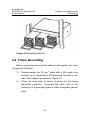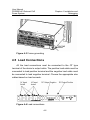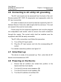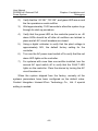
1
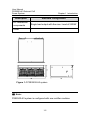
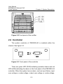
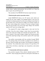
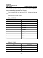
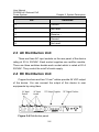
PSE2500-A3
External PoE Power System
User Manual
Hangzhou Huawei-3Com Technology Co., Ltd
http://www.huawei-3com.com
Manual Version: V1.00
Copyright © 2006, Hangzhou Huawei-3Com Technology
Co., Ltd. and its licensors
All Rights Reserved
No part of this manual may be reproduced or transmitted in any form
or by any means without prior written consent of Hangzhou
Huawei-3Com Technology Co., Ltd.
Trademarks
H3C, Aolynk,
, IRF, H3Care,
, Neocean,
, TOP
G, SecEngine, SecPath, COMWARE, VVG, V2G, VnG, PSPT,
NetPilot, and XGbus are trademarks of Hangzhou Huawei-3Com
Technology Co., Ltd.
All other trademarks that may be mentioned in this manual are the
property of their respective owners.
Notice
The information in this document is subject to change without notice.
Every effort has been made in the preparation of this document to
ensure accuracy of the contents, but all statements, information, and
recommendations in this document do not constitute the warranty of
any kind, express or implied.
To obtain the latest information, please access:
Technical Support
[email protected]
http://www.huawei-3com.com
About This Manual
Organization
H3C PSE2500-A3 External PoE Power System User Manual is
organized as follows:
Chapter
Contents
1 Introduction
Introduces the concept and
features of power supply.
2 System Description
Introduces the structure and
electrical connection of power
supply.
3 Safety
Introduces the safety information of
the overall system.
4 Installation and Debugging
5 Engineering Maintenance
and Troubleshooting
Introduces the installing and
debugging of the overall system.
Introduces the routine
maintenance and troubleshooting
of the system.
Conventions
The manual uses the following conventions:
I. Command conventions
Convention
Description
Boldface
The keywords of a command line are in
Boldface.
italic
Command arguments are in italic.
[]
Items (keywords or arguments) in square
brackets [ ] are optional.
{ x | y | ... }
Alternative items are grouped in braces
and separated by vertical bars. One is
selected.
[ x | y | ... ]
Optional alternative items are grouped in
square brackets and separated by vertical
bars. One or none is selected.
{ x | y | ... } *
Alternative items are grouped in braces
and separated by vertical bars. A minimum
of one or a maximum of all can be selected.
[ x | y | ... ] *
Optional alternative items are grouped in
square brackets and separated by vertical
bars. Many or none can be selected.
#
A line starting with the # sign is comments.
II. GUI conventions
Convention
<>
Description
Button names are inside angle brackets.
For example, For example, click <OK>.
Convention
Description
[]
Window names, menu items, data table
and field names are inside square
brackets. For example, pop up the [New
User] window.
/
Multi-level menus are separated by forward
slashes. For example, [File/Create/Folder].
III. Symbols
Convention
Warning
Caution
Note
Description
Means reader be extremely careful.
Improper operation may cause bodily
injury.
Means reader be careful. Improper
operation may cause data loss or damage
to equipment.
Means a complementary description.
Environmental Protection
This product has been designed to comply with the requirements
on environmental protection. For the proper storage, use and disposal
of this product, national laws and regulations must be observed.
User Manual
PSE2500-A3 External PoE
Power System
Table of Contents
Table of Contents
Chapter 1 Introduction ..................................................................1-1
1.1 Architecture and Configurations.........................................1-1
1.2 Features .............................................................................1-3
Chapter 2 System Description .....................................................2-1
2.1 Overview ............................................................................2-1
2.1.1 Rectifier ...................................................................2-1
2.1.2 Rectifier Bracket ......................................................2-2
2.1.3 Rectifier Visual Displays..........................................2-2
2.2 Controller............................................................................2-3
2.3 AC Distribution Unit............................................................2-6
2.4 DC Distribution Unit............................................................2-6
Chapter 3 Safety ............................................................................3-1
3.1 Safety Statements..............................................................3-1
3.2 Warning Statements and Safety Symbols .........................3-2
3.3 Precautions ........................................................................3-3
Chapter 4 Installation and Debugging.........................................4-1
4.1 Introduction ........................................................................4-1
4.1.1 Guidelines................................................................4-1
4.1.2 EMI Considerations .................................................4-1
4.1.3 Installation Tools and Hardware..............................4-1
4.1.4 Safety ......................................................................4-2
4.1.5 Installation Sequence ..............................................4-2
4.2 Physical Mounting ..............................................................4-3
i
User Manual
PSE2500-A3 External PoE
Power System
Table of Contents
4.3 Installing Rectifiers .............................................................4-4
4.4 Frame Grounding ...............................................................4-5
4.5 Load Connections ..............................................................4-6
4.6 Connecting to AC utility/ AC grounding .............................4-7
4.7 Initial Start-up .....................................................................4-7
4.8 Powering on the Device .....................................................4-7
Chapter 5 Engineering Maintenance and Troubleshooting ......5-1
5.1 Maintenance and Troubleshooting.....................................5-1
5.2 LED Indication....................................................................5-1
5.3 Regulatory compliance standards......................................5-3
ii
User Manual
PSE2500-A3 External PoE
Power System
Chapter 1 Introduction
Chapter 1 Introduction
1.1 Architecture and Configurations
PSE2500-A3 power system is the extremely flexible system with
strong functions which are designed for PoE application.It can provide
power of up to 2500 W with 1+1 redundant configuration.
PSE2500-A3 architecture integrates two rectifiers (maximum 3
rectifiers), a system controller, and the distribution module in a 4U high
chassis. Local monitor and control of the device status can be
implemented with the system controller.
The general configuration is shown as follows:
Table 1-1 PSE2500-A3 configuration
Description
Standard Configuration
4U high chassis
D x W x H- 380 x 486 x 175mm(14.96 x
19.13x6.89 in)
System
controller
One
NP series
Rectifier
One NP2500UAC-PoE
AC distribution
components
1) Three independent lines AC power input each
of socket – with an individual switch
2) 3-phase AC voltage sensor
1-1
User Manual
PSE2500-A3 External PoE
Power System
Chapter 1 Introduction
Description
Standard Configuration
DC distribution
components
Single load output with the max. Load of 2500W
Other
-
Figure 1-1 PSE2500-A3 system
Note:
PSE2500-A3 system is configured with one rectifier modules.
1-2
User Manual
PSE2500-A3 External PoE
Power System
Chapter 1 Introduction
1.2 Features
PSE2500-A3 system has the following features:
z
Compatible with a wide range of input voltages from 90Vac
to 264Vac (configured with NP2500UAC-PoE rectifiers).
z
Each bracket is configured with three rectifiers.
z
Power factor is above 0.99 and efficiency is over 88% .
z
Maximum device output 2500W.
z
System Controller can real-time monitor and operate the
system.
z
Applying hot-swappable components to accomplish quick
installation.
z
Achieving remote control through RS232 or RS485
interface.
z
Advanced EMC design.
z
High Safety and reliability.
(1)(2)(3): NP2500UAC-PoE Rectifier
Figure 1-2 PSE2500-A3 configuration (I)
1-3
User Manual
PSE2500-A3 External PoE
Power System
Chapter 1 Introduction
(a): AC Input Socket
(c): RS232 and RS485
(b): DC Output
(d): Frame Ground
Figure 1-3 PSE2500-A3 configuration (II)
1-4
User Manual
PSE2500-A3 External PoE
Power System
Chapter 2 System Description
Chapter 2 System Description
2.1 Overview
Figure 2-1 shows the schematic diagram of the PSE2500-A3
power system, showing the interconnections and signal flow among
the modules and components.
Figure 2-1 Schematic diagram of the PSE2500-A3
2.1.1 Rectifier
The output bus power is supplied by the rectifiers.
2-1
User Manual
PSE2500-A3 External PoE
Power System
Chapter 2 System Description
2.1.2 Rectifier Bracket
Up to three rectifiers can be mounted in each system of rectifier
bracket. Each rectifier in the bracket receives AC power from the AC
distribution.
2.1.3 Rectifier Visual Displays
The front panel of the rectifier has three LEDs. Their names,
colors and meanings are as follows.
Table 2-1 LEDs state description
AC OK
(green)
Condition
DC OK
(green)
Fault
(Red)
All OK
1
1
0
Thermal alarm
(Ambient)
1
0
0
Thermal alarm (fan fail)
1
0
1
Blown AC fuse in unit
1
0
1
Low or no AC > 15mS
(single unit)
0
0
0
AC not present in any
rectifier
0
0
0
Over Voltage Latched
shutdown
1
0
1
Any internal failure
1
0
1
The Front panel of the rectifier is as follows.
2-2
User Manual
PSE2500-A3 External PoE
Power System
Chapter 2 System Description
Figure 2-2 Front panel of the rectifier
2.2 Controller
The system controller of PSE2500-A3 is installed within the
chassis. See figure 2-3.
Figure 2-3 Front panel of the controller
There are green LED (RUN) indicating operation status and red
LED (ALM) indicating the alarm on the front panel of the PSE2500-A3
controller. When the system has an alarm, such as input failure, input
over-voltage or under-voltage, output over-voltage or under-voltage,
2-3
User Manual
PSE2500-A3 External PoE
Power System
Chapter 2 System Description
rectifier failure, rectifier self-protection, the red LED is on. Once the
alarm is gone, the red LED goes off.
The controller of the PSE2500-A3 has two major functions:
I. Monitoring the system operation status
Inside PSE2500-A3 there is an AC sensor card, which can
sample the AC input voltage. The sampled signal is sent into the
controller for data processing. Once the input voltage is lower than the
pre-set alarm level of the input low voltage, the controller reports an
AC input under-voltage alarm. Likewise, if the input voltage is higher
than the pre-set alarm level of the input high voltage, the controller
reports an AC input over-voltage alarm.
The sampled DC output voltage signal is also sent into the
controller. Once the output voltage is lower than the pre-set alarm
level of the output low voltage, the controller will reports a DC
Low
alarm. Likewise, if the output voltage is higher than the pre-set alarm
level of the output high voltage, the controller reports a DC output high
alarm.
The rectifier communicates with the controller through RS485
bus. The working status of the rectifier is passed to the controller in
this way. Once the rectifier has an alarm, the information is passed to
the controller. The rectifier failure alarm includes: AC input failure, DC
output failure, fan failure, output high, over temperature, and module
shut-down.
II. Communicate with deamon systems
The controller supports China national standard protocol YD/T
1104-2001. User can apply this protocol to read system information or
2-4
User Manual
PSE2500-A3 External PoE
Power System
Chapter 2 System Description
command the operation through equipment which has RS232 or
RS485 interface and can support this protocol.
There is one RS485 port and one RS232 interface on the rear
panel.
Their definitions are as follows:
Table 2-2 RS232
Pin
Definition
1
Not used
2
Receive
3
Transmit
4
Not used
5
Ground
6
Not used
7
Not used
8
Not used
9
Not used
Table 2-3 RS485
Pin
Definition
1
Transmit, +
2
Transmit, -
3
Receive, +
2-5
User Manual
PSE2500-A3 External PoE
Power System
Chapter 2 System Description
Pin
Definition
4
Ground
5
Not used
6
Receive, -
7
Ground
8
Not used
2.3 AC Distribution Unit
There are three AC input sockets on the rear panel of the device
rating at 20 A, 250VAC. Each socket supplies one rectifier module.
There are three switches beside each socket which is rated at 20 A
250VAC. They control the on/off of each supply.
2.4 DC Distribution Unit
Copper bus bars and two 10 mm2 cables provide 54 VDC output
of the device. You can connect the output of this device to user
equipments by using them.
Figure 2-4 Distribution panel
2-6
User Manual
PSE2500-A3 External PoE
Power System
Chapter 3 Safety
Chapter 3 Safety
3.1 Safety Statements
Please read and follow all safety instructions and warnings before
servicing the PSE2500-A3 system. Reference the individual module
product manuals for additional safety statements specific to the
modules.
z
The device must be in a restricted access area (dedicated
equipment rooms, equipment closets, or the like) where the
applicable requirements of the device are met.
z
The equipment must be in a controlled environment (an area
where the humidity is maintained at levels that cannot cause
condensation on the equipment, the contaminating dust is
controlled, and the steady-state ambient temperature is
within the range specified).
z
Do not install this equipment at a combustible place.
z
This equipment has been evaluated for use in a continuous
ambient temperature of up to 50°C.
z
Torque electrical connections conform to the values
specified on labels or in the product documentation.
z
Refer to the product documentation for the proper hardware.
Use only the parts specified in the equipment documentation
z
Improper fuses/circuit breakers may cause body injury or
equipment damages.
z
External circuit breakers must be sized as required by the
applicable local codes. Refer to the equipment ratings to
3-1
User Manual
PSE2500-A3 External PoE
Power System
Chapter 3 Safety
assure rating of equipment no to exceed 80% of the value of
the breaker chosen.
3.2 Warning Statements and Safety Symbols
The symbols may sometimes be accompanied by some types of
statement, for example “Hazardous voltage/energy inside”, “Risk of
injury”. “This device must be accessed only by qualified personnel.”
This symbol identifies the need to refer to
the equipment instructions for important
information.
This symbol is used to identify the
protective safety earth ground for the
equipment.
This symbol is used to identify other
bonding points within the equipment.
This symbol is used to identify the
presence of hazardous ac or dc
voltages.It may also be used to warn of
hazardous energy levels
Note:
These symbols are used to identify the presence of hazardous AC/DC
main voltage and also can be used to alarm the level of danger.
3-2
User Manual
PSE2500-A3 External PoE
Power System
Chapter 3 Safety
3.3 Precautions
When working on this type of equipment, the following
precautions must be noted:
z
This unit must be installed, serviced, and operated only by
skilled and qualified personnel who have the necessary
knowledge
and
practical
experience
with
electrical
equipment and who understand the hazards that can arise
when working on this equipment.
z
The PSE2500-A3 system can be powered by multiple AC
inputs. Ensure that the appropriate circuit protection device
for each AC input being serviced is disconnected before
servicing the equipment.
z
High leakage currents may be possible on this type of
equipment. Make sure the equipment is properly earth
grounded before connecting power.
z
Hazardous energy and voltages are present in the device
and on the interface cables that can shock or cause serious
injury. Follow all safety warnings and practices when
servicing this equipment.
z
Exercise care when servicing this area.
In addition to proper job training and safety procedures, the
following are some basic precautions that should always be used:
z
Use only properly insulated tools.
z
Remove all metallic objects (key chains, glasses, rings,
watches, or jewelry, and so on).
z
Wear safety glasses.
z
Test circuits before touching.
3-3
User Manual
PSE2500-A3 External PoE
Power System
z
Chapter 3 Safety
Lock out and tag any circuit breakers/fuses when possible to
prevent accidental turn on.
z
Be aware of potential hazards before servicing equipment.
z
Identify
exposed
hazardous
electrical
potentials
on
connectors or, wirings. (Note the condition of these circuits,
especially any wiring).
z
Be careful when removing or replacing any covers – avoid
contacting any circuits.
3-4
User Manual
PSE2500-A3 External PoE
Power System
Chapter 4 Installation and
Debugging
Chapter 4 Installation and Debugging
4.1 Introduction
This section outlines the sequence for installing the PSE2500-A3
device, including plug-in modules, as well as test procedures for
verifying the integrity of the installation.
4.1.1 Guidelines
The device may be installed to allow rear and front access. All
cables may be routed through conduit openings, and all the operation
can be completed on the front side.
4.1.2 EMI Considerations
When running the dc output cables, pair the positive and negative
conductors over as much of their length as possible to minimize loop
areas.
4.1.3 Installation Tools and Hardware
You will need the following tools and hardware to install and test
the PSE2500-A3 unit:
z
Wire cutters and strippers
z
Heat shrink gun and appropriately sized heat-shrink tubing
z
Electric screwdriver with 6 mm (0.24 in.) hex head with
variable torque range, 0 to 120 in lbs (0 to 13.6 N.m)
z
Adjustable wrench
z
M8 sleeve
4-1
User Manual
PSE2500-A3 External PoE
Power System
Chapter 4 Installation and
Debugging
z
Digital meter with an accuracy of ± 0.02%
z
Small flat screw driver
z
ESD wrist strap
4.1.4 Safety
Warning:
z
Only qualified personnel can install and service the PSE2500-A3
device.
z
Hazardous energy is present in the device and on the interface
cables, and ill shock or cause serious injury or death if safety
precautions are ignored. Follow all safety warnings and practices
when servicing this equipment.
4.1.5 Installation Sequence
Review all safety warnings in Section 3 before beginning the
installation process. Observe all warnings and labels on the
equipment.
The PSE2500-A3 system consists of a chassis in which includes
AC and DC distribution modules, one system controller, and one
rectifier bracket. Refer to Figures 2-6 and figure 2-7 for relationship of
components.
4-2
User Manual
PSE2500-A3 External PoE
Power System
Chapter 4 Installation and
Debugging
Note that the PSE2500-A3 is shipped to the customer site mostly
pre-assembled so as to minimize the overall installation process. The
following installation sequence is recommended
z
Physical mounting
z
Installing rectifiers
z
Frame grounding
z
Connecting to loads
z
Connecting to AC utility/AC grounding
z
Initializing the system
4.2 Physical Mounting
All items needed for a site are contained within the packing crate.
The ordered rectifiers may be shipped separately. Please check the
packing list.
1)
Place the crate in its vertical position near the installation
site.
2)
Carefully remove the crate top and sides and then the
packing material. If possible, recycle the packing crate and
the packing material. If not, dispose of properly.
3)
Within the packing crate may be the following items: chassis,
rectifiers, and cables. Remove all this material and place
aside.
4)
Install the chassis into the 19-inch standard cabinet by using
eight pieces of M6 screws. Notes that use the electric
screwdriver and correct torque setting (recommend 6.2 to
6.5 N.m). See figure 4-1.
4-3
User Manual
PSE2500-A3 External PoE
Power System
Chapter 4 Installation and
Debugging
Figure 4-1 Physical installation
4.3 Installing Rectifiers
Standalone rectifier is installed by sliding into the power bracket,
pushing until the rectifier is fully inserted, and closing the handle on
the rectifier.
1)
Verify that the AC circuit breakers in the distribution module
are in the “OFF” position
2)
Place the module in the bracket and slide it toward the
backplane until it contacts the backplane
3)
Close the handle on the front of the rectifier and verify that
the rectifier is firmly seated.
See Figure4-2 for the rectifier installation.
4-4
User Manual
PSE2500-A3 External PoE
Power System
Chapter 4 Installation and
Debugging
Figure 4-2 Installing rectifiers
4.4 Frame Grounding
Before connecting the electrical cables to the system, you must
first ground the frame.
1)
Recommended the 16 mm2 cable with a M6 single hole
terminal lug is connected to PE grounding terminal on the
rear of the chassis, as shown in Figure 4-3.
2)
Follow all local rules in terms of colors for the frame
grounding conductor. Terminate the other end of the
conductor to a grounding plate or other acceptable ground
point.
4-5
User Manual
PSE2500-A3 External PoE
Power System
Chapter 4 Installation and
Debugging
Figure 4-3 Frame grounding
4.5 Load Connections
All the load connections must be connected to the OT type
terminal of the device’s output cable. The positive load cable must be
connected to load positive terminal and the negative load cable must
be connected to load negative terminal. Choose the appropriate size
cables based on load currents.
Figure 4-4 Load connections
4-6
User Manual
PSE2500-A3 External PoE
Power System
Chapter 4 Installation and
Debugging
4.6 Connecting to AC utility/ AC grounding
The AC main inputs can be accessed from the back of the unit.
Recommended IEC 320C-19 plug/socket and appropriate cable for
AC input connection.
AC cable for branch circuit must be sized as required by the U.S.
National Electric Code (the cable length shall be minimum 1.5m and
not exceed 4.5m) and /or local codes.
Power plugs for the equipment appliance inlet must be plugged
into independent wall socket outlet to ensure the earth connection
through the supply. The socket outlet shall be installed near the
equipment and shall be easily accessible.
The AC utility connection must follow this procedure:
1)
Turn off the AC input switch.
2)
Plug the AC input power cord into the corresponding AC
socket.
For related connection position see figure 4-4.
4.7 Initial Start-up
The device is ready to be powered up. First, verify that all AC
branch circuit breakers are OFF.
4.8 Powering on the Device
z
Ensure that all rectifiers are locked into position in the
bracket with the front handle.
z
Turn the AC service circuit breakers ON.
z
Turn the AC branch circuit breakers ON.
1)
Turn the AC switches of rectifiers ON.
4-7
User Manual
PSE2500-A3 External PoE
Power System
2)
Chapter 4 Installation and
Debugging
Verify that the “AC OK”, “DC OK”, and green LED are on and
the fan operates on each rectifier.
3)
Wait approximately 10-30 seconds to allow the system to go
through its start-up procedure.
4)
Verify that the green LED on the controller panel is on. All
alarm LEDs should be off after all rectifiers are latched in
place and all AC circuit breakers are closed.
5)
Using a digital voltmeter to verify that the plant voltage is
approximately 54V, the default factory setting for the
controller.
6)
Turn one the AC power input switch off to verify that the red
alarm LED lights on the controller.
7)
For systems with more than one rectifier installed, turn the
second AC input switch off to verify that the FAULT LED
lights on the controller. Clear the alarms by turning the AC
circuit breaker on.
When the system shipped from the factory, normally all the
systems parameters have been configured as the default value.
Contact Hangzhou Huawei-3Com Technology Co., Ltd. if special
setting is needed.
4-8
User Manual
PSE2500-A3 External PoE
Power System
Chapter 5 Engineering
Maintenance and
Troubleshooting
Chapter 5 Engineering Maintenance
and Troubleshooting
5.1 Maintenance and Troubleshooting
This section provides field maintenance and troubleshooting
information and procedures for the power system. Before performing
the maintenance procedures, review the safety information in Section
3.
Warning:
All procedures described in this section must be performed by
qualified maintenance personnel only.
The power devices are repaired by replacement. Contact
Hangzhou Huawei-3Com Technology Co., Ltd. for more details.
5.2 LED Indication
Use the following table to determine if there is any problem with
PSE2500-A3 power system with a controller.
When visual indicators do not identify a defective part, notify
Hangzhou Huawei-3Com Technology Co., Ltd.
5-1
User Manual
PSE2500-A3 External PoE
Power System
Chapter 5 Engineering
Maintenance and
Troubleshooting
Table 5-1 Troubleshooting guide
Controller
alarm
status
Rectifier
display
Possible
problems
z
RUN
ALM
NONE
z
RUN
AC OK
ALM
FAULT
RUN
ALM
RUN
ALM
AC OK
DC OK
FAULT
AC OK
The
AC
power input
circuit
breakers
has
operated.
AC
input
voltage
is
too low or
power lost
Possible solution
z
z
Verify that AC power
input circuit breaker
is closed; close
circuit breaker if it is
open.
Verify the AC power
is present and in
normal range
Rectifier failure
Output beyond
normal range
Replace the rectifier
Communication
error between
the rectifier and
the controller
Replace the rectifier
Rectifier has no
output and it is
in standby
mode;
Command the rectifier
to work or reset the
controller
Over load;
Check if the load is over
the rating.
Ambient
temperature is
too high
Check the ambient
temperature.
Rectifier failure;
5-2
Replace the rectifier
User Manual
PSE2500-A3 External PoE
Power System
Controller
alarm
status
Rectifier
display
ALM or
None
any
Chapter 5 Engineering
Maintenance and
Troubleshooting
Possible
problems
Controller
failure
Possible solution
Replace the controller
5.3 Regulatory compliance standards
Table 5-2 Regulatory compliance standards
Discipline
Standards
FCC Part 15 (CFR 47) Class A
CISPR 22 Class A
EMC
EN 55022 Class A
AS/NZS CISPR 22 Class A
ETSI EN 300 386 V1.3.2
EN 55024
UL 60950-1
CSA C22.2 No 60950-1
Safety
IEC 60950-1
EN 60950-1
AS/NZS 60950-1
5-3