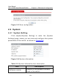
1
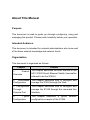
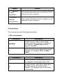
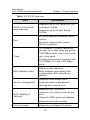
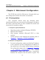
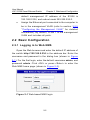
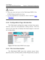
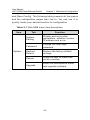
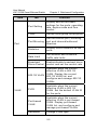
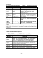
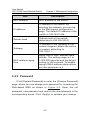
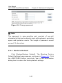
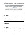
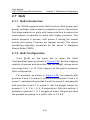
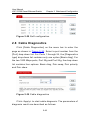
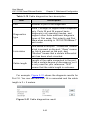
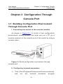
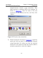
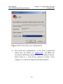
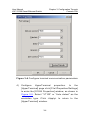
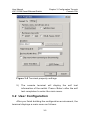
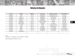
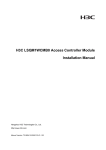
H3C S1526 Smart Ethernet Switch
User Manual
Hangzhou H3C Technologies Co., Ltd.
http://www.h3c.com
Manual Version: T2-UM-20070516-3.02
Copyright © 2005-2007, Hangzhou H3C Technologies Co.,
Ltd.
All Rights Reserved
No part of this manual may be reproduced or transmitted in any form
or by any means without prior written consent of Hangzhou H3C
Technologies Co., Ltd.
Trademarks
H3C,
, Aolynk,
, H3Care,
, TOP G,
, IRF,
NetPilot, Neocean, NeoVTL, SecPro, SecPoint, SecEngine, SecPath,
Comware, Secware, Storware, NQA, VVG, V2G, VnG, PSPT, XGbus,
N-Bus, TiGem, InnoVision and HUASAN are trademarks of Hangzhou
H3C Technologies Co., Ltd.
All other trademarks that may be mentioned in this manual are the
property of their respective owners.
CE
This equipment complies with the following European Directives:
89/336/EEC (electromagnetic compatibility), 73/23/EEC (low voltage).
Notice
The information in this document is subject to change without notice.
Every effort has been made in the preparation of this document to
ensure accuracy of the contents, but all statements, information, and
recommendations in this document do not constitute the warranty of
any kind, express or implied.
To obtain the latest information, please access:
http://www.h3c.com
Technical Support
[email protected]
http://www.h3c.com
About This Manual
Purpose
This document is used to guide you through configuring, using and
managing this product. Please read it carefully before your operation.
Intended Audience
This document is intended for network administrators who know well
of the basic network knowledge and network terms.
Organization
This document is organized as follows:
Chapter
Content
1
Product
Overview
This chapter describes the main features of the
H3C S1526 Smart Ethernet Switch (hereinafter
referred to as the S1526).
2
Web-based
Configuration
This chapter describes how to configure and
manage the S1526 through the Web.
3 Configuration
Through
Console Port
This chapter describes how to configure and
manage the S1526 through the command line
interface.
4
Typical
Configuration
This chapter describes a typical network
configuration example of the S1526.
Chapter
Content
5 Appendix –
TCP/IP
Installation
This chapter describes how to install the TCP/IP
protocol on your computer.
6 Appendix – IP
Address
Configuration
This chapter describes how to configure an IP
address on your computer.
Conventions
The manual uses the following conventions:
I. GUI conventions
Convention
Description
Boldface
Window names, button names, field
names, and menu items are in Boldface.
For example, the New User window
appears; click OK.
>
Multi-level menus are separated by angle
brackets. For example, File > Create >
Folder.
Convention
Description
<>
Button names are inside angle brackets.
For example, For example, click <OK>.
[]
Window names, menu items, data table
and field names are inside square
brackets. For example, pop up the [New
User] window.
Convention
Description
Multi-level menus are separated by forward
slashes. For example, [File/Create/Folder].
/
II. Symbols
Convention
Description
Caution
Means reader be careful. Improper
operation may cause data loss or damage
to equipment.
Note
Means a complementary description.
User Manual
H3C S1526 Smart Ethernet Switch
Table of Contents
Table of Contents
Chapter 1 Product Overview ..........................................1-1
1.1 Introduction .........................................................1-1
1.2 Features .............................................................1-1
Chapter 2 Web-based Configuration .............................2-1
2.1 Prerequisites .......................................................2-1
2.2 Basic Configuration .............................................2-2
2.2.1 Logging in to Web NMS ..............................2-2
2.2.2 Configuration Page Introduction .................2-3
2.2.3 Title Item Description .................................2-3
2.2.4 Button Description ......................................2-6
2.2.5 User Session Timeout ................................2-7
2.3 Save Configuration ..............................................2-7
2.4 System ...............................................................2-8
2.4.1 System Setting ...........................................2-8
2.4.2 Password ...................................................2-9
2.4.3 Restore Default ........................................ 2-10
2.4.4 Reboot ..................................................... 2-11
2.4.5 Upgrade ................................................... 2-12
2.5 Port .................................................................. 2-14
2.5.1 Port Setting ............................................. 2-14
2.5.2 Trunk ....................................................... 2-17
2.5.3 Port Mirroring ........................................... 2-20
2.5.4 Statistics .................................................. 2-22
2.5.5 Rate Limit ................................................ 2-26
i
User Manual
H3C S1526 Smart Ethernet Switch
Table of Contents
2.5.6 Broadcast Storm Control .......................... 2-28
2.6 VLAN ................................................................ 2-29
2.6.1 VLAN Types ............................................. 2-29
2.6.2 802.1Q VLAN ........................................... 2-30
2.6.3 Port-based VLAN ..................................... 2-37
2.7 QoS .................................................................. 2-41
2.7.1 QoS Introduction ...................................... 2-41
2.7.2 QoS Configuration .................................... 2-41
2.8 Cable Diagnostics ............................................. 2-42
2.9 Logout .............................................................. 2-44
Chapter 3 Configuration Through Console Port ............3-1
3.1 Building Configuration Environment Through Console
Port ..........................................................................3-1
3.2 User Configuration ..............................................3-5
3.2.1 Changing Web-based NMS Password .........3-6
3.2.2 Setting IP Addresses ..................................3-7
3.2.3 Restoring Factory Default Settings .............3-7
3.2.4 Saving the Current Configuration ................3-8
3.2.5 Configuring the Management VLAN ............3-9
3.2.6 Rebooting the Switch ............................... 3-12
Chapter 4 Typical Configuration ...................................4-1
4.1 Network Requirements ........................................4-1
4.2 Networking Diagram ............................................4-3
4.3 Configuration Steps .............................................4-3
Chapter 5 Appendix – TCP/IP Installation .....................5-1
Chapter 6 Appendix – IP Address Configuration ...........6-1
ii
User Manual
H3C S1526 Smart Ethernet Switch
Chapter 1 Product Overview
Chapter 1 Product Overview
1.1 Introduction
H3C S1526 Smart Ethernet Switch (hereinafter referred to
as the S1526) is suitable for the networking of small and
medium-sized enterprises, Internet cafe and households. It
provides one console port, 24 × 10/100Base-TX autosensing
Ethernet ports and two 1000 Mbps uplink combo ports.
Note:
Port 25 and port 26 are 1000 Mbps uplink combo ports. Each
combo port supports one 10/100/1000Base-T autosensing
Ethernet port and one 1000 Mbps SFP module port, which,
however, cannot work simultaneously. If both are enabled
simultaneously, the SFP module port, which has a higher
priority, will be active, while the 10/100/1000Base-T port will be
inactive.
1.2 Features
The S1526 offers rich features as listed below.
1-1
User Manual
H3C S1526 Smart Ethernet Switch
Chapter 1 Product Overview
Table 1-1 S1526 features
Item
VLAN (virtual local
area network)
Port
Description
Supports up to 256 IEEE 802.1Q
compliant VLANs
Supports up to 26 port-based
VLANs
All ports support broadcast storm
control
All ports support flow control,
802.3x compliant
10/100Base-TX ports: two trunk
groups, up to four ports per group
Trunk
1000 Mbps ports: one trunk group,
up to two ports
A trunk group cannot contain both
10/100Base-TX and 1000 Mbps
ports
Address auto-learning
MAC address table
MAC address auto-aging time
configurable (300 seconds by
default)
Supports Web-based NMS
Device management
Supports basic management
through the console port
Supports 802.1p priority
QoS (Quality of
Service)
Supports four priority queues per
port
Supports WRR queue scheduling
Supports port rate limiting
Port mirroring
Supports port-based mirroring
1-2
User Manual
H3C S1526 Smart Ethernet Switch
Chapter 1 Product Overview
Item
Description
Port statistics
Supports traffic flow and type
statistics
Cable Diagnostics
Diagnosis of parameter such as
operating status and length of port
connecting cables
Note:
NMS = Network Management System
1-3
User Manual
H3C S1526 Smart Ethernet Switch
Chapter 2 Web-based Configuration
Chapter 2 Web-based Configuration
The S1526 has a built-in Web server, through which you
can manage and maintain the switch conveniently.
2.1 Prerequisites
Your
computer
should
meet
the
following
basic
requirements before you can access the Web page to configure
the switch, assuming that you have installed the switch and
connected all necessary cables.
I. Computer system/hardware
z
Operating system installed (Windows XP/2000)
z
Network card installed
z
Web browser installed (Microsoft IE5.5 or later
version)
z
TCP/IP protocol suite installed and enabled (refer to
Chapter 5 “ Appendix – TCP/IP Installation ”)
II. Network configuration
z
For local configuration, make sure that the IP address
of the computer and the management IP address of
the switch are in the same subnet before accessing
the configuration page (refer to Chapter 6 “ Appendix
–
IP
Address
configuration,
Configuration ”);
make sure the
For
remote
route connectivity
between the computer and the switch is good. The
2-1
User Manual
H3C S1526 Smart Ethernet Switch
Chapter 2 Web-based Configuration
default management IP address of the S1526 is
192.168.0.234, and subnet mask 255.255.255.0.
z
Assign the Ethernet port connected to the computer to
be in the management VLAN (refer to section 3.2.5
“ Configuring the Management VLAN ” for detailed
information). By default, VLAN 1 is the management
VLAN and includes all ports.
2.2 Basic Configuration
2.2.1 Logging in to Web NMS
Open the Web browser and enter the default IP address of
the switch http://192.168.0.234 in the address bar. Enter the
username and password in the dialog box (shown in Figure
2-1 ). For the first login, enter the default username admin, and
password admin. Click <OK> or press <Enter> to enter the
Web NMS home page (shown in Figure 2-2 ).
Figure 2-1 Web-based NMS login
2-2
User Manual
H3C S1526 Smart Ethernet Switch
Chapter 2 Web-based Configuration
Caution:
z
Only one user can log in to the Web-based NMS of the
S1526 Ethernet switch at a time.
z
For the modification of password, refer to section 2.4.2
“ Password ”.
2.2.2 Configuration Page Introduction
The Web-based configuration page includes three parts:
title bar, menu bar and parameter setting section. Click the
items in the menu bar to display the desired page to view and
set configuration.
Figure 2-2 Web-based NMS home page
2.2.3 Title Item Description
The Web-based NMS menu bar contains seven items:
[System], [Port], [VLAN], [QoS], [Cable Diagnostics], [Logout],
2-3
User Manual
H3C S1526 Smart Ethernet Switch
Chapter 2 Web-based Configuration
and [Save Config]. The following table presents all the menus
and the configuration pages they link to. You can use it to
quickly locate your desired section for configuration.
Table 2-1 Web NMS menu item description
Item
System
Tab
Function
System
Setting
Display and set system
parameters: software version,
IP address and so on
Password
Change the user login
password
Restore
Default
Restore the factory default
settings
Reboot
Allow the user to reboot the
switch remotely
Upgrade
Enter the maintenance mode
and upgrade software
2-4
User Manual
H3C S1526 Smart Ethernet Switch
Item
Tab
Function
Port Setting
Display and set the basic
settings for the ports: operating
rate, duplex mode and flow
control
Trunk
Set the trunk group for the ports
Port Mirroring
Set the monitor port, mirroring
port and inbound/outbound
direction
Statistics
Display traffic statistics on the
ports
Rate Limit
Set inbound and outbound
traffic rate limits
Broadcast
Storm Control
Enable/disable broadcast storm
control and set the control rate
802.1Q VLAN
Available when the current
effective VLAN is 802.1Q
VLAN. Display the current
802.1Q VLAN list, and
configure and manage 802.1Q
VLANs
PVID
Available when the current
effective VLAN is 802.1Q
VLAN. Set the default VLAN ID
for the ports
Port-based
VLAN
Available when the current
effective VLAN is port-based
VLAN. Display port-based
VLAN list, and configure and
manage port-based VLANs
Advanced
Change VLAN type
Port
VLAN
Chapter 2 Web-based Configuration
2-5
User Manual
H3C S1526 Smart Ethernet Switch
Item
Chapter 2 Web-based Configuration
Tab
Function
QoS
QoS
Set mapping relation between
queues and priorities, and
queue weight
Cable
Diagnosti
cs
Cable
Diagnostics
Diagnose operating status and
parameters such as length for
port cables
Logout
—
Log out the Web configuration
page
Save
Config
Save Config
Save the configurations to the
EEPROM of the switch
Note:
EEPROM = Electrically Erasable Programmable Read Only
Memory
2.2.4 Button Description
Table 2-2 Web-based NMS button description
Button
Function
Help
Open the online help page of the Web-based
NMS, which provides the help information
related to operations on the current page
Apply
Submit the input information and confirm the
current system information
Cancel
Cancel the current configuration input
Refresh
Refresh the configuration at the current page
2-6
User Manual
H3C S1526 Smart Ethernet Switch
Chapter 2 Web-based Configuration
2.2.5 User Session Timeout
If your session is inactive for a certain period of time after
you log in to the Web-based NMS, you will be automatically
logged out and the system will display the [Web-based NMS
Login] dialog box shown in Figure 2-1 . The changes you have
made to the configuration during your session, however, will
remain on the Web page. To resume your operation, you need
to log in again.
Note:
The user session timeout time is 300 seconds.
2.3 Save Configuration
When configuring the switch, remember to save your
configurations
timely
in
order
to
prevent
the
loss
of
configuration information.
Click [Save Config] on the menu bar to enter a page as
shown in Figure 2-3 . Click <Save> and click <Yes> on the
confirmation dialog box. Then the configuration information of
the switch is saved to the EEPROM of the switch. The switch
will
automatically
load
the
newly
saved
configuration
information next time it reboots and any unsaved configuration
information will be lost.
2-7
User Manual
H3C S1526 Smart Ethernet Switch
Chapter 2 Web-based Configuration
Figure 2-3 Save configuration
2.4 System
2.4.1 System Setting
Click [System/System Setting] to enter the [System
Settings] page, where you can view and configure the system
parameters of the switch, as shown in Figure 2-4 .
Figure 2-4 System information
Table 2-3 System information item description
Item
Software version
Description
Version of the software currently
used in the switch.
2-8
User Manual
H3C S1526 Smart Ethernet Switch
Chapter 2 Web-based Configuration
Item
Description
MAC address
MAC address of the switch.
IP address
IP address of the switch. By
entering this address, you can log
in the Web-based configuration
page. The default IP address of the
switch is 192.168.0.234.
Subnet mask
Subnet mask of the switch,
defaulting to 255.255.255.0.
Gateway
IP address of the gateway of the
network segment where the switch
is located, defaulting to
192.168.0.1.
MAC address aging
time
Aging time of MAC address table
entries. The setting range is 0 to
1,000,000 seconds and the default
setting is 300 seconds. To disable
aging of MAC address table entries,
set this parameter to 0.
2.4.2 Password
Click [System/Password] to enter the [Change Password]
page, where you can change your password for accessing the
Web-based NMS as shown in Figure 2-5 . Enter the old
password, new password and confirm the new password in the
corresponding boxes. Click <Apply> to validate your change.
2-9
User Manual
H3C S1526 Smart Ethernet Switch
Chapter 2 Web-based Configuration
Figure 2-5 Change password
Note:
The password is case-sensitive and consists of non-null
character(s) that can be directly input with keyboard, excluding
space and quotation marks. The length of password cannot
exceed 12 characters.
2.4.3 Restore Default
Click [System/Restore Default]. The [Restore Factory
Default Settings] page appears, as shown in Figure 2-6 . Click
the <RESTORE> button, and click <Yes> in the confirmation
dialog box to restore the factory default settings.
2-10
User Manual
H3C S1526 Smart Ethernet Switch
Chapter 2 Web-based Configuration
Figure 2-6 Restore factory default settings
Caution:
Once
the
factory
default
settings
are
restored,
all
configurations such as the user name, password, and IP
address are restored to the default settings. Use the default
user name, password and IP address to log in.
2.4.4 Reboot
Caution:
Save the configurations before you reboot the switch.
Otherwise, all the unsaved configurations will be lost.
2-11
User Manual
H3C S1526 Smart Ethernet Switch
Chapter 2 Web-based Configuration
This operation allows you to reboot the switch remotely
Click [System/Reboot] to enter the [Reboot Switch] dialog
box, as shown in Figure 2-7 .
Figure 2-7 Reboot the switch
Click the <REBOOT> button, and click <Yes> in the
confirmation dialog box to reboot the switch and return to the
[Web-based NMS Login] screen, as shown in Figure 2-1 .
2.4.5 Upgrade
The S1526 Ethernet switch supports online software
upgrade. Take the following steps:
1)
Click
[System/Upgrade].
The
[Upgrade
Switch
Software] dialog box appears, as shown in Figure 2-8 .
Figure 2-8 Upgrade switch software
2-12
User Manual
H3C S1526 Smart Ethernet Switch
2)
Chapter 2 Web-based Configuration
Click the <ENTER MAINTENANCE MODE> button to
enter the [Enter Maintenance Mode] page, as shown
in Figure 2-9 .
Figure 2-9 Entering maintenance mode
Caution:
Once you click <CONTINUE> and enter the [Software Upgrade]
page, you cannot go back to the previous step. If you do not
want to proceed with software upgrade, you need to manually
reboot the switch.
3)
When the <WAIT...> button changes to <CONTINUE>,
click <CONTINUE> to enter the [Upgrade Software]
page, as shown in Figure 2-10 . Click <Browse> on the
[Upgrade Software] page, select the latest “.bin” file,
and
then
click
<Upgrade>.
The
system
automatically perform the software upgrade.
2-13
will
User Manual
H3C S1526 Smart Ethernet Switch
Chapter 2 Web-based Configuration
Figure 2-10 Software upgrade
2.5 Port
2.5.1 Port Setting
I. Displaying port information
Click [Port/Port Setting] to enter the [Port Setting] page, as
shown in Figure 2-11 .
2-14
User Manual
H3C S1526 Smart Ethernet Switch
Chapter 2 Web-based Configuration
Figure 2-11 Port setting
This page displays the basic information of each port, as
described below:
Table 2-4 Port setting item description
Item
Description
Port
Port number, corresponding to the
identification on the front panel of the switch.
You can set properties of a port by clicking its
number.
Speed
Actual operating rate of the port, displayed as
“--“ if this port is not connected.
Duplex
The duplex mode of the port, displayed as
“--“ if the port is not connected.
Link
Indicates the linkage state of the port,
displayed as “--“ if not connected.
Priority
Priority of the port.
Flow
control
Indicates whether flow control is enabled.
2-15
User Manual
H3C S1526 Smart Ethernet Switch
Chapter 2 Web-based Configuration
Item
Admin
Description
Indicates whether the port is enabled to
forward data. In the case of “Disabled”, this
port cannot forward data.
II. Setting port properties
Click the port number (for example, 01) to enter the [Port
Properties] page, as shown in Figure 2-12 .
Figure 2-12 Port properties
In this page you can set the properties of the selected port.
The properties of a port are as follows:
2-16
User Manual
H3C S1526 Smart Ethernet Switch
Chapter 2 Web-based Configuration
Table 2-5 Port property item description
Item
Description
Port
Number of the port currently being
configured.
Speed
Three options available: auto-negotiation, 10
Mbps, and 100 Mbps. For port 25 and port 26
there is one more option: 1 Gbps. If port
trunking is enabled on the port, the speed
cannot be changed.
Duplex
Three duplex modes available:
auto-negotiation, half duplex and full duplex.
Note that the duplex mode cannot be
changed if port trunking is enabled on the
port.
Admin
Sets the data forwarding status for the port. A
port cannot forward data if it is set to
“disabled”.
Priority
Priority of the port, raging from 0 to 7. Refer
to section 2.7.2 “ QoS Configuration ” for
details.
Flow control
Enables/disables the flow control function for
the port. This setting is available only when
the current port is set to “enabled”.
2.5.2 Trunk
I. Port trunking introduction
The port trunking feature allows you to set multiple ports to
one trunk group, so that the incoming/outgoing loads are
2-17
User Manual
H3C S1526 Smart Ethernet Switch
Chapter 2 Web-based Configuration
shared among the member ports. This feature increases
bandwidth and enhances connection reliability.
Three load distribution algorithms for physical links are
available to implement port trunking: source MAC-based (SA),
destination MAC-based (DA), and source & destination
MAC-based (SA+DA).
II. Ethernet port trunking configuration
Click [Port/Trunk] to enter the [Trunk Algorithm] page, as
shown in Figure 2-13 . Follow these steps:
1)
Select a link distribution algorithm in the [Trunk
Algorithm] drop-down list.
2)
Set the quantity of trunk groups and the member
port(s) in each trunk group by selecting from the
single-selection boxes.
3)
Click <Apply> to complete the configuration.
2-18
User Manual
H3C S1526 Smart Ethernet Switch
Chapter 2 Web-based Configuration
Note:
z
If you set the VLAN properties for a member port of a trunk
group, the VLAN properties of the other ports in that trunk
group will change accordingly.
z
If port mirroring is enabled on a port or port isolation is
enabled on the corresponding VLAN, port trunking cannot
be configured on that port.
z
Port trunking is not enabled for ports in the normal group.
z
Each trunk group supports 2 to 4 ports.
z
For trunking ports, the duplex mode must be full duplex, and
the speed setting must be the same and cannot be
auto-negotiation.
Example: As shown in Figure 2-13 , set ports 01, 02, 03
and 04 in trunk group 1, and select [Source & Destination
MAC-based] as the trunk algorithm.
2-19
User Manual
H3C S1526 Smart Ethernet Switch
Chapter 2 Web-based Configuration
Figure 2-13 Trunk
2.5.3 Port Mirroring
I. Port mirroring introduction
The S1526 supports the port mirroring function. With this
function enabled, a copy of the data on one or more ports can
be forwarded to the monitor port for traffic analysis and
monitoring. For example, you can copy the packets on port 2 to
the designated monitor port 1, so that you can analyze the
traffic and record the working status of port 2 by using the
protocol analyzer connected to port 1.
II. Monitor port configuration
Click [Port/Port Mirroring] to enter the [Port Mirroring
Settings] page as shown in Figure 2-14 . Follow these steps:
2-20
User Manual
H3C S1526 Smart Ethernet Switch
1)
Chapter 2 Web-based Configuration
Select the [Enable port mirroring] check box on the
[Port Mirroring Setting] page.
2)
Type the number of the port which you want to set as
the monitor port in the [Monitor Port] input box.
3)
Select the [Mirroring port] option button. If the [Normal
port] option button is selected, this port will not be set
as a mirroring port. Note that a port cannot be
configured as a monitor port and a mirroring port at the
same time.
4)
Choose
the
inbound/outbound
direction
of
the
mirroring port:
z
Inbound: only the incoming packets on the port will be
mirrored to the monitor port;
z
Outbound: only the outgoing packets on the port will
be mirrored to the monitor port;
z
Both: both the incoming and outgoing packets on the
port will be mirrored to the monitor port.
5)
Click <Apply> to complete the configuration.
Example: As shown in Figure 2-14 , set port 1 as the
monitor port to analyze and monitor the incoming packets on
port 2, the outgoing packet on port 3 and both the incoming and
outgoing packets on port 4.
2-21
User Manual
H3C S1526 Smart Ethernet Switch
Chapter 2 Web-based Configuration
Figure 2-14 Port mirroring setting
2.5.4 Statistics
The port statistics function is used to count the packets
and bytes across ports. You can view the traffic and packet
type on the ports, to help locate network problems.
Click [Port/Statistics] to enter the [Port Statistics] page, as
shown in Figure 2-15 . Click <CLEAR> to clear the port
statistics information, and click <REFRESH> to refresh the
statistics information.
2-22
User Manual
H3C S1526 Smart Ethernet Switch
Chapter 2 Web-based Configuration
Figure 2-15 Port statistics
To view the detailed statistics information of a port, click
the port number. Figure 2-16 shows an example of detailed
port statistics information.
2-23
User Manual
H3C S1526 Smart Ethernet Switch
Chapter 2 Web-based Configuration
Figure 2-16 Port statistics
Table 2-6 describes the error packets received on the port.
Table 2-6 Description of error packets
Packet
Description
Port-received packet
Runts error
The number of packets that have a valid
CRC and that are less than 64 bytes
long.
Giants error
The number of packets that have a valid
CRC and that are greater than 1,518
bytes long.
2-24
User Manual
H3C S1526 Smart Ethernet Switch
Chapter 2 Web-based Configuration
Packet
Description
CRC error
The number of error packets that are
between 64 to 1,518 bytes long.
Frame error
The number of packets that are
between 64 to 1,518 bytes long and that
have a frame check sequence (FCS)
with a non-integral number of bytes.
Sum of the following quantities:
z
Aborts error
z
z
Ignored error
The number of packets that have a
bad CRC and that are less than 64
bytes long.
The number of packets that have a
bad CRC and that are greater than
1,518 bytes long.
The total number of times a valid
length (64 to 1,518 bytes) packet is
received and at least one invalid
data symbol is detected.
The number of good packets that are
dropped due to lack of network
resources.
Port-sent packet
Sum of the following quantities:
z
Aborts error
z
z
The number of packets that have a
bad CRC and that are less than 64
bytes long.
The number of packets that have a
bad CRC and that are greater than
1,518 bytes long.
The total number of times a valid
length (64 to 1,518 bytes) packet is
received and at least one invalid
data symbol is detected.
2-25
User Manual
H3C S1526 Smart Ethernet Switch
Chapter 2 Web-based Configuration
Packet
Description
Deferred error
The number of packets transmitted by a
port for which the first transmission
attempt is delayed because the medium
is busy.
Collisions error
The number of collisions experienced
by a port during packet transmissions.
Late collisions
error
The number of times a collision is
detected later than 512 bit-times into
the transmission of a packet.
Note:
Cyclic redundancy check (CRC) is a technology whereby to
check the errors of a data frame.
2.5.5 Rate Limit
With the rate limit enabled, the rate of packets coming into
or leaving the port will be limited, to ensure the smooth
operation of the network.
Click [Port/Rate Limit] to enter the [Rate Limit] page, as
shown in Figure 2-17 , where you can see the rate limit status
of each port. The symbol “--” indicates that no rate limit is
applied. Click a port number to enter the [Rate Limit
Configuration] page, as shown in Figure 2-18 , where you can
set the rate limit for the port.
2-26
User Manual
H3C S1526 Smart Ethernet Switch
Chapter 2 Web-based Configuration
Figure 2-17 Rate limit
For example, as shown in Figure 2-18 , set the rate limit for
incoming traffic on port 4 to 64 kbps, and that for outgoing
traffic to 2 Mbps.
Figure 2-18 Rate limit configuration
2-27
User Manual
H3C S1526 Smart Ethernet Switch
Chapter 2 Web-based Configuration
2.5.6 Broadcast Storm Control
With the broadcast storm control function enabled, if the
broadcast traffic exceeds the predefined limit, the system will
drop broadcast packets beyond the limit until the ratio of
broadcast packets comes down to a reasonable value. In this
way, broadcast storms can be effectively controlled and
network congestion can be avoided, thus ensuring the smooth
operation of the network.
Click
[Port/Broadcast
Storm
Control]
to
enter
the
[Broadcast Storm Control] page as shown in Figure 2-19 .
Follow these steps:
1)
Select [Disable] or [Enable].
2)
If you select [Enable], the broadcast storm control
function will be enabled. You can then select the rate
of broadcast storm control, which can be 5%, 10%,
20% or 100%. The smaller the percentage is, the
lower broadcast traffic will be permitted to pass. 100%
means no control.
3)
Click <Apply> to complete the configuration.
Figure 2-19 Broadcast storm control
2-28
User Manual
H3C S1526 Smart Ethernet Switch
Chapter 2 Web-based Configuration
2.6 VLAN
Virtual local area network (VLAN) is a technology that
allows you to assign network segments to devices within a LAN
logically rather than physically, to create virtual work groups.
With the VLAN technology, the network administrator can
divide a physical LAN into different broadcast domains (namely,
VLANs) logically, with each VLAN consisting of a group of
computers having the same needs. Since VLAN is divided
logically rather than physically, computers in the same VLAN
do not need to be located in the same physical area. In other
words, these computers do not have to belong to the same
physical LAN segment.
2.6.1 VLAN Types
The S1526 supports two types of VLANs: 802.1Q VLAN
and port-based VLAN. Click [VLAN/Advanced] to enter the
[Select VLAN Type] page, as shown in Figure 2-20 . Select a
VLAN type from the drop-down list and click <Apply> to change
the VLAN type.
Figure 2-20 VLAN type selection
2-29
User Manual
H3C S1526 Smart Ethernet Switch
Chapter 2 Web-based Configuration
Caution:
If the type of a VLAN is changed, all the previously made VLAN
settings will be cleared.
2.6.2 802.1Q VLAN
Caution:
In the 802.1Q VLAN mode, you can only manage the switch via
a port belonging to the management VLAN. The default
management VLAN of the S1526 is VLAN 1. To modify the
management VLAN, refer to section 3.2.5
“ Configuring the
Management VLAN ”.
I. Display
Click [VLAN/802.1Q VLAN] to view VLANs, as shown in
Figure 2-21 . 10 VLANs are displayed per page, in the
ascending order of the VLAN IDs. Click <Previous> or <Next>
to view other existing VLANs.
2-30
User Manual
H3C S1526 Smart Ethernet Switch
Chapter 2 Web-based Configuration
Figure 2-21 View VLANs
The parameters in the figure above are described as
follows:
Table 2-7 802.1Q VLAN item description
Item
Description
VLAN ID
VLAN ID, ranging from 1 to 4094. To configure
a VLAN, click the corresponding VLAN ID.
Port list
List of ports in the VLAN. Note that you can
set one port as a member port of multiple
VLANs.
Port
isolation
Displays the status of VLAN port isolation
function. This feature enables you to isolate
specific ports so that they cannot
communicate with one another even if they
belong to the same VLAN, thus to enhance the
network security and allow for flexible network
design.
Delete
Click to delete the current VLAN.
2-31
User Manual
H3C S1526 Smart Ethernet Switch
Item
Chapter 2 Web-based Configuration
Description
To query a VLAN, enter its VLAN ID in the
[VLAN ID] input box under [VLAN query] and
click <QUERY>. The matched VLAN, if it
exists, will be displayed.
VLAN
Query
II. Create
Click the <New> button on the right of the page shown in
Figure 2-21 to enter a VLAN creation page as shown in Figure
2-22 . The icons on the page and their descriptions are listed in
Table 2-8 .
Table 2-8 VLAN icon description
Icon
Description
This port does not belong to this VLAN.
This port belongs to this VLAN and the
outgoing packets from this port will be tagged.
This port belongs to this VLAN and the
outgoing packets from this port will be
untagged.
Take the following steps:
1)
Enter the VLAN ID you want to create in the [VLAN ID]
text box in the page, as shown in Figure 2-22 .
2)
To change the VLAN properties of a port, click the icon
below each port. To perform configuration to all ports,
click the icon below “All”.
2-32
User Manual
H3C S1526 Smart Ethernet Switch
3)
Chapter 2 Web-based Configuration
You can set the port isolation function for the VLAN.
Select the <Enable port isolation> check box at first,
and then input the uplink port number. The uplink port
is used to connect the upper-level switch or router.
This step is optional.
4)
Click the <Apply> button and continue to configure
PVID of the VLAN member ports. Refer to section
2.6.2 IV. “ Configuring PVID ” for PVID configuration.
Caution:
If port isolation is enabled for a VLAN, the member ports of that
VLAN cannot belong to any other VLAN.
For example, as shown in Figure 2-22 , create a VLAN with
the ID 10, set ports 3, 4, 5, and 6 as member ports of VLAN 10,
untag outgoing packets on ports 3 and 4, and tag outgoing
packets on ports 5 and 6.
2-33
User Manual
H3C S1526 Smart Ethernet Switch
Chapter 2 Web-based Configuration
Figure 2-22 Create a VLAN
2-34
User Manual
H3C S1526 Smart Ethernet Switch
Chapter 2 Web-based Configuration
Note:
z
A VLAN ID can range from 2 to 4094. VLAN 1 is the default
management VLAN of the switch and it includes all ports by
default. VLAN 1 cannot be deleted.
z
After you create a VLAN, configure PVID of the VLAN in the
“PVID configuration” page. Refer to section 2.6.2 IV.
“ Configuring PVID ” for PVID configuration.
z
Tag: Every Ethernet frame in an IEEE802.1Q-based VLAN
has a tag, which contains information of frame priority and
of the VLAN that this frame belongs to, and so on. Generally
if a port is connected to a PC, frames do not need to be
tagged on this port; if it is connected to another IEEE
802.1Q-compliant switch, it is recommended to tag frames.
z
Refer to Chapter 4 “ Typical Configuration ” for information
about 802.1Q VLAN configuration.
III. Modify
Click the VLAN ID in the page shown in Figure 2-21 to
enter the [VLAN Modification] page as shown in Figure 2-23 ,
where you can modify the settings to that VLAN. Refer to
section 2.6.2
II. “ Create ” for interface description and
configuration modification. Skip the first step and follow all the
rest steps described in section 2.6.2 II. “ Create ”.
2-35
User Manual
H3C S1526 Smart Ethernet Switch
Chapter 2 Web-based Configuration
Figure 2-23 VLAN modification
Note:
If you modify the VLAN configuration of a port that belongs to a
trunk group, the VLAN configurations of the other member
ports of that trunk group will change accordingly.
IV. Configuring PVID
PVID is the default VLAN ID for all ports.
Click [VLAN/PVID] to enter the PVID display page, as
shown in Figure 2-24 . Click the port number to enter the [PVID
Configuration] page for that port, as shown in Figure 2-25 , and
set the PVID settings.
2-36
User Manual
H3C S1526 Smart Ethernet Switch
Chapter 2 Web-based Configuration
Figure 2-24 PVID display
Figure 2-25 PVID configuration
2.6.3 Port-based VLAN
The S1526 supports up to 26 port-based VLANs. One port
can belong to multiple port-based VLANs.
I. Display
Use the method described in section 2.6.1 “ VLAN Types ”
to set the VLAN type to port-based VLAN. Enter the
[Port-based VLAN] screen. Each page can display the
information of 10 port-based VLANs. Click <Next Page> to
2-37
User Manual
H3C S1526 Smart Ethernet Switch
Chapter 2 Web-based Configuration
view the information of other VLANs. The [Port List] field on
this screen lists the ports belonging to this VLAN.
Figure 2-26 Port-based VLAN
The description of the parameters in the figure above is as
follows:
Table 2-9 Port-based VLAN item description
Item
Description
VLAN ID
Port-based VLAN ID. Click the VLAN ID to
enter the configuration page for that
VLAN.
Port list
List of ports belonging to this VLAN. A
port can belong to multiple port-based
VLANs.
Port isolation
Displays VLAN port isolation status.
Delete
Click to delete the current VLAN.
II. Create
As shown in the figure above, click <New> on the right to
enter the [Create Port-based VLAN] page, as shown in Figure
2-27 .
2-38
User Manual
H3C S1526 Smart Ethernet Switch
1)
Chapter 2 Web-based Configuration
Enter the port-based VLAN ID in the [Port-based
VLAN ID] text box.
2)
Select from the port icons the ports to be included in
this port-based VLAN. Click the port icon to mark it
with
, which indicates this port belongs to this
port-based VLAN.
3)
In the [Port isolation] column, you can set the port
isolation function for the port-based VLAN. First
enable the port isolation function, and then input the
number of the uplink port to be isolated. The uplink
port is used for connecting the upper-level switch or
router. This step is optional.
4)
Click <Apply> on the right to complete and validate the
configuration.
For example, as shown in Figure 2-27 , create port-based
VLAN 7 and set port 7 and port 8 as member ports of this VLAN.
Figure 2-27 Create a port-based VLAN
2-39
User Manual
H3C S1526 Smart Ethernet Switch
Chapter 2 Web-based Configuration
III. Modify
Click the port number in Figure 2-26 to enter the [VLAN
Modification] page, where you can modify the settings of that
VLAN. Refer to section 2.6.2
II. “ Create ” for detailed
configuration steps. All steps are the same except the first one,
which is unnecessary for modification purpose.
Figure 2-28 VLAN modification
Note:
If you modify the VLAN configuration of a port that belongs to a
trunk group, the VLAN configurations of the other member
ports of that trunk group will change accordingly.
2-40
User Manual
H3C S1526 Smart Ethernet Switch
Chapter 2 Web-based Configuration
2.7 QoS
2.7.1 QoS Introduction
The S1526 supports basic QoS function. With proper port
priority settings, when network congestion occurs, the system
first drops packets on ports with lower priorities to ensure the
transmission of packets on ports with higher priorities. The
switch supports 4 queues, with queue 0 having the lowest
priority and queue 3 having the highest priority. The queue
scheduling algorithm supported by the switch is Weighted
Round Robin (WRR).
2.7.2 QoS Configuration
Click [QoS] on
the
menu bar
to
enter
the
[QoS
Configuration] page, as shown in Figure 2-29 . Set the mapping
relation of queues and priorities, and the weight, whose value
can range from 1 to 15. Click <Apply> on the right to complete
QoS configuration.
For example, as shown in Figure 2-29 , set packets with
priorities 0 and 1 in queue 0, packets with priorities 2 and 3 in
queue 1, packets with priorities 4 and 5 in queue 2, and packets
with priorities 6 and 7 in queue 3. Set the weight values for
queues 0, 1, 2, 3 to 1, 2, 4, 8 respectively. With this setting, if
packets in queues 0, 1, 2, 3 congest on a port, the port will send
the packets according to a traffic ratio of 1:2:4:8.
2-41
User Manual
H3C S1526 Smart Ethernet Switch
Chapter 2 Web-based Configuration
Figure 2-29 QoS configuration
2.8 Cable Diagnostics
Click [Cable Diagnostics] on the menu bar to enter the
page as shown in Figure 2-30 . Select a port number from the
[Port] drop-down list. For Ports 1 through 24, the [Diagnostics
type] drop-down list contains only one option [Basic diag]. For
the two 1000 Mbps ports, Port 25g and Port 26g, the drop-down
list contains four options: Basic diag, Pair swap, Pair polarity
and Pair skew.
Figure 2-30 Cable diagnostics
Click <Apply> to start cable diagnosis. The parameters of
diagnosis result are described as follows:
2-42
User Manual
H3C S1526 Smart Ethernet Switch
Chapter 2 Web-based Configuration
Table 2-10 Cable diagnostics item description
Item
Description
Port
Number of port to be diagnosed.
Diagnostics
type
Ports 1 through 24 support basic diagnosis
only. Ports 25 and 26 support basic
diagnosis in all operation modes, and
support other three additional diagnosis
types of Pair swap, Pair polarity and Pair
skew when working in 10/100/1000Base-T
port mode.
Link status
Link status of the port. “Connected” means
a link is present on the port; “Open” means
no link is present on the port; and
“Shorted” means that a certain differential
pair has been short-circuited.
Cable length
Length of the cable connected to the port.
It has a certain degree of discrepancy, so it
is only used for your reference. “N/A”
means that the cable length is unknown.
For example, Figure 2-31 shows the diagnosis results for
Port 16. You can see that Port 16 is connected and the cable
length is 3 ± 5 meters.
Figure 2-31 Cable diagnostics result
2-43
User Manual
H3C S1526 Smart Ethernet Switch
Chapter 2 Web-based Configuration
Caution:
z
The cable diagnostics function is not suitable for optical
fiber cables.
z
Do not plug or unplug the cable during the cable diagnostics
process.
2.9 Logout
Click [Logout] in the [Web-based NMS] screen and click
<Yes> on the confirmation dialog box to log out.
Note:
You cannot exit normally from the Web-based NMS by closing
the Web browser directly. In such case you must wait for about
five minutes before you can log in again.
2-44
User Manual
H3C S1526 Smart Ethernet Switch
Chapter 3 Configuration Through
Console Port
Chapter 3 Configuration Through
Console Port
3.1 Building Configuration Environment
Through Console Port
I. Connecting the switch to the console terminal
As shown in Figure 3-1 , to build a local configuration
environment, simply connect the serial port on a PC (or a
console terminal) to the console port of the switch by using a
console cable.
Figure 3-1 Build configuration environment through
console port
II. Configuring terminal parameters
1)
Click [Start/Programs/Accessories/Communications],
and
run
the
terminal
3-1
emulation
program
User Manual
H3C S1526 Smart Ethernet Switch
Chapter 3 Configuration Through
Console Port
(HyperTerminal). Create a new connection. Take
HyperTerminal in Windows 2000 as an example. As
shown in Figure 3-2 , enter the name of the new
connection in the [Name] text box, and then click
<Apply>.
Figure 3-2 Create a new connection
2)
Select a serial port. As shown in Figure 3-3 , select the
serial port that you want to use from the [Connect
using] drop-down list (make sure that the selected
serial port is the same port that the console cable is
actually connected to), and click <Apply>.
3-2
User Manual
H3C S1526 Smart Ethernet Switch
Chapter 3 Configuration Through
Console Port
Figure 3-3 Connection port configuration
3)
Set serial port parameters. In the [Port properties]
dialog box as shown in Figure 3-4 , set [Bits per
second] to 9600 bps, [Data bits] to 8, [Parity] to None,
[Stop bits] to 1, and [Flow control] to None. Click
<Apply> to enter the [HyperTerminal] window.
3-3
User Manual
H3C S1526 Smart Ethernet Switch
Chapter 3 Configuration Through
Console Port
Figure 3-4 Configure terminal communication parameters
4)
Configure
HyperTerminal
properties.
In
the
[HyperTerminal] page click [File//Properties/Settings]
to enter the [S1526 Properties] window, as shown in
Figure 3-5 . Select “VT100” or “Auto detect” as the
emulation type. Click <Apply> to return to the
[HyperTerminal] window.
3-4
User Manual
H3C S1526 Smart Ethernet Switch
Chapter 3 Configuration Through
Console Port
Figure 3-5 Terminal property settings
5)
The console terminal will display the self test
information of the switch. Press <Enter> after the self
test completes to enter the main menu.
3.2 User Configuration
After you finish building the configuration environment, the
terminal displays a main menu as follows:
3-5
User Manual
H3C S1526 Smart Ethernet Switch
MAIN
Chapter 3 Configuration Through
Console Port
MENU
1. Modify password
2. Set IP address/Subnet mask/Gateway
3. Reset to default configuration
4. Save current configuration
5. Modify management VLAN
0. Reboot
Enter your choice (0-5):
3.2.1 Changing Web-based NMS Password
As prompted, type 1 on the main menu to enter the
password setting page. Enter the old password first, and then
the new password. Enter the new password again to confirm
the new password. The system will return to the main menu
after the password is successfully changed.
Note:
The password is case-sensitive and consists of non-null
character(s) that can be directly input with keyboard, excluding
space and quotation marks. The length of password cannot
exceed 12 characters.
3-6
User Manual
H3C S1526 Smart Ethernet Switch
Chapter 3 Configuration Through
Console Port
3.2.2 Setting IP Addresses
Type 2 on the main menu to go to the IP address
configuration page. Set the IP address of the switch first, and
then the subnet mask, followed by the gateway IP address. The
system will return to the main menu after successful
configuration.
For example, set the IP address of the switch to
192.168.0.2, subnet mask to 255.255.255.0 and gateway IP
address to 192.168.0.1.
Select your choice (0-4):2
IP: 192.168.0.2
Subnet mask: 255.255.255.0
Gateway: 192.168.0.1
IP Configuration Completed
3.2.3 Restoring Factory Default Settings
Type 3 on the main menu. The system will prompt you to
restore the factory default settings. Type Y and press <Enter>.
The system will start restoring the factory default settings of
the switch, and will return to the main menu after the default
settings are successfully restored.
3-7
User Manual
H3C S1526 Smart Ethernet Switch
Chapter 3 Configuration Through
Console Port
Caution:
Once the switch has been restored to the factory default
settings, all configurations including the user name, password
and IP address of the switch will be restored to the default
settings. Use the default user name, password and IP address
to log in.
3.2.4 Saving the Current Configuration
Type 4 on the main menu. The system will prompt you to
save the current configuration to the switch. Type Y and press
<Enter>. The system will start saving the configuration to the
switch and will return to the main menu after the configuration
is successfully saved, and then return to the main menu.
3-8
User Manual
H3C S1526 Smart Ethernet Switch
Chapter 3 Configuration Through
Console Port
3.2.5 Configuring the Management VLAN
Caution:
z
On the S1526, you can configure the management VLAN
only in 802.1Q VLAN mode. In the port-based VLAN mode,
the management VLAN function is not supported.
z
The S1526 can only have one management VLAN at a time.
The valid management VLAN is the currently created or
modified management VLAN. The original management
VLAN will not be valid any longer.
z
When configuring the management VLAN, stop using the
Web-based NMS. The change of the management VLAN will
terminate the Web connection of the switch.
z
After changing the management VLAN, log in to the
Web-based NMS using the new management VLAN port. To
query the management VLAN and corresponding ports,
refer to section 3.2.5 I. “ Query the Management VLAN and
Corresponding Ports ”.
I. Query the Management VLAN and Corresponding
Ports
Enter 5 on the main menu. The system displays the
currently used management VLAN. Press <Enter> to view the
management VLAN ID and corresponding ports as follows:
3-9
User Manual
H3C S1526 Smart Ethernet Switch
Chapter 3 Configuration Through
Console Port
Management VLAN ID(1-4094): 1
Ports(pvid) in the management VLAN:
1( 1)
2( 1)
3( 1)
4( 1)
5( 1)
6( 1)
7( 1)
8( 1)
9( 1) 10( 1) 11( 1) 12( 1) 13( 1) 14( 1) 15( 1)
16( 1)
17( 1) 18( 1) 19( 1) 20( 1) 21( 1) 22( 1) 23( 1)
24( 1)
25( 1) 26( 1)
II. Create Management VLAN and Add Port
Enter 5 on the main menu and input a new VLAN ID to be
created as the management VLAN in the field “Management
VLAN ID (1-4094)”. The VLAN ID should between 1 and 4,094.
For example, create a management VLAN 3, and add Port
5 to the management VLAN.
Management VLAN ID(1-4094): 3
Add management port(1-26): 5
VLAN 3 is created and port 5 is added to VLAN 3
successfully!
III. Change Management VLAN and Add Port
Enter 5 on the main menu, input the new management
VLAN ID in the field “Management VLAN ID(1-4094):”, and add
a port to the management VLAN.
For example, add Port 3 to the management VLAN 3.
Management VLAN ID(1-4094): 3
Ports(pvid) in the management VLAN:
3-10
User Manual
H3C S1526 Smart Ethernet Switch
Chapter 3 Configuration Through
Console Port
2( 3)
Add another port?(Y/N):y
Add management port(1-26): 3
Port 3 is added to VLAN 3 successfully!
For example, change the management VLAN to be the
existing VLAN 2, and add Port 3 to the management VLAN.
Management VLAN ID(1-4094): 2
Ports(pvid) in the management VLAN:
6( 2)
9( 2)
Add another port?(Y/N):y
Add management port(1-26): 3
Port 3 is added to VLAN 2 successfully!
Note:
z
The port number ranges from 1 to 26. In a command line,
you can only add one port to the management VLAN at a
time.
z
When you add a port to the management VLAN in a
command line, the PVID of the port is automatically changed
to be the ID of the management VLAN.
z
To remove a port from the management VLAN, log in to the
Web-based NMS for configuration. For details, refer to
section 2.6.2 “ 802.1Q VLAN ”.
3-11
User Manual
H3C S1526 Smart Ethernet Switch
Chapter 3 Configuration Through
Console Port
3.2.6 Rebooting the Switch
Type 0 on the main menu. The system prompts you to
reboot the switch. Type Y and press <Enter>. The system will
start rebooting and will load the newly saved configuration
information from its EEPROM.
Caution:
Save your configurations before you reboot the switch.
Otherwise all the unsaved configurations will be lost.
3-12
User Manual
H3C S1526 Smart Ethernet Switch
Chapter 4 Typical Configuration
Chapter 4 Typical Configuration
4.1 Network Requirements
Company A wants to establish a local-area network (LAN)
by using the S1526 switch. PCs of the Finance Dept., which
can only be used for inner purpose and cannot have Internet
access, must be isolated from PCs of other departments, which
require Internet access by connecting to an uplink switch
through the S1526 and an uplink speed of 2 Gbps. In addition,
the S1526 should be able to be managed remotely by a
management computer.
To meet the network requirements above, we can design
the network in the following way:
z
Use a S5000P switch as the uplink switch of the
S1526.
z
Set the VLAN type to 802.1Q VLAN.
z
Assign ports 1 to 4 (100 Mbps) to four PCs of the
Finance Dept., and add ports 1 through 4 to VLAN
200.
z
Assign ports 5 through 24 (100 Mbps) to the 19 PCs of
the other departments and add these ports to VLAN
10.
z
Add ports 25 and 26 (1000 Mbps) of the S1526 to
VLAN 10 and VLAN 1 (default management VLAN).
Connect
port
25
and
respectively.
4-1
port
26
to
the
S5000P
User Manual
H3C S1526 Smart Ethernet Switch
z
Chapter 4 Typical Configuration
Enable port trunking on port 25 and port 26 to increase
the bandwidth.
z
Connect a computer to the S5000P to manage the
S1526. Note that the port to which the management
computer is connected should be in VLAN 1 (default
management VLAN).
Note:
z
You can also use other gigabit switch as the uplink switch of
the S1526, provided this uplink switch should support port
trunking.
z
Make sure to configure the port of the uplink switch to which
the S1526 is connected in VLAN 1.
z
You need to enable port trunking on the ports of the S5000P
connected with the S1526.
4-2
User Manual
H3C S1526 Smart Ethernet Switch
Chapter 4 Typical Configuration
4.2 Networking Diagram
Figure 4-1 S1526 802.1Q VLAN typical configuration
4.3 Configuration Steps
Launch the Web browser and type the default IP address
of the switch http://192.168.0.234 (this address can be
modified after login) in the address bar. Press <Enter> and a
login dialog box appears. Type the default username admin
and password admin in the login dialog box. Click <OK> to
enter the Web configuration page.
1)
Select the VLAN type. Click [VLAN/Advanced] to enter
the [VLAN Type] page as shown in Figure 4-2 . Select
the 802.1Q VLAN from the drop down list (system
default).
4-3
User Manual
H3C S1526 Smart Ethernet Switch
Chapter 4 Typical Configuration
Figure 4-2 VLAN type
2)
Create a VLAN. Click the [802.1Q VLAN] tab to enter
the [VLAN Management] page. Click the <Create>
button on the right of the page to enter the [VLAN
Create] page as shown in Figure 4-3 . Type 200 in the
[VLAN ID] text box and add ports 1 through 4 to VLAN
200 by setting the port icons to
. Click <OK> to
validate the setting.
Figure 4-3 Create a VLAN
3)
To block the PCs of the Finance Dept. from accessing
the Internet and keep them isolated with other PCs,
you need to remove ports 1 through 4 from VLAN 1.
Click the [802.1Q VLAN] tab and then click [VLAN ID 1]
to enter the [VLAN Modify] page, as shown in Figure
4-4 . Remove ports 1 through 4 from VLAN 1.
4-4
User Manual
H3C S1526 Smart Ethernet Switch
Chapter 4 Typical Configuration
Figure 4-4 Modify a VLAN
4)
Modify the port PVID. Click the [PVID Configuration]
tab and click the port ID to enter the port PVID setting
page. All port PVIDs are 1 by default. Change the port
PVID to 200 for ports 1 through 4 one by one, as
shown in Figure 4-5 . Click <OK> to validate the
settings, as shown in Figure 4-6 .
Figure 4-5 Port PVID setting
4-5
User Manual
H3C S1526 Smart Ethernet Switch
Chapter 4 Typical Configuration
Figure 4-6 Port PVID
5)
Add ports 5 through 26 to VLAN 10. Repeat the
previous steps 2 to 4: create VLAN 10, add ports 5
through 26 to VLAN 10 (note that the port icons of
ports 25 and 26 should be set to
ports be set to
and those of other
), remove ports 5 through 24 from
VLAN 1 and set port PVID to 10 for ports 5 through 24.
6)
Enable port trunking for ports 25 and 26. Click
[Port/Trunk] to enter the following page. Set ports 25
and 26 in the same trunk group and click <OK>. Note
that for trunking ports, the duplex mode must be full
duplex, and the speed setting must be the same and
cannot be auto-negotiation.
4-6
User Manual
H3C S1526 Smart Ethernet Switch
Chapter 4 Typical Configuration
Figure 4-7 Port trunking
4-7
User Manual
H3C S1526 Smart Ethernet Switch
7)
Chapter 4 Typical Configuration
Save configuration. Click [Save Config] after you have
completed the configuration and click <Save> to save
the configuration you have made. The configurations
will take effective after reboot.
8)
The network design is completed. After installation of
the S1526, assign ports 1 through 4 to PCs of the
Finance Dept. and ports 5 through 24 to PCs of other
departments. Connect ports 25 and 26 of the S1526 to
the S5000P and connect one computer to the S5000P
to manage the S1526. Note that this management
computer should be in VLAN 1.
4-8
User Manual
H3C S1526 Smart Ethernet Switch
Chapter 5 Appendix – TCP/IP
Installation
Chapter 5 Appendix – TCP/IP
Installation
The PC through which you configure the S1526 must have
the TCP/IP protocol suite installed. If you are not sure whether
TCP/IP is installed, follow these steps.
Caution:
The following steps are based on Windows 2000.
1)
Choose [Start/Settings/Control Panel]. Double-click
the [Network and Dial-up Connection] icon to open the
[Network
Connection]
window.
Right-click
one
connection and then select [Properties] to check if
TCP/IP has been installed to the designated network
interface card on the computer. If not, click <Install>.
5-1
User Manual
H3C S1526 Smart Ethernet Switch
Chapter 5 Appendix – TCP/IP
Installation
Figure 5-1 Local area connection properties
2)
Double click <Protocol> from the network component
type list, or click <Protocol> and then click <Add>.
5-2
User Manual
H3C S1526 Smart Ethernet Switch
Chapter 5 Appendix – TCP/IP
Installation
Figure 5-2 Select network component type
3)
Select [Microsoft] from the [Manufacturers] list, and
double-click [TCP/IP] in the [Network Protocol] list or
click [TCP/IP], and then click <OK>. You will return to
the [Network] window a few seconds later, and you
can see “TCP/IP” on the list of installed network
components.
5-3
User Manual
H3C S1526 Smart Ethernet Switch
Chapter 5 Appendix – TCP/IP
Installation
Figure 5-3 Select network protocol
5-4
User Manual
H3C S1526 Smart Ethernet Switch
Chapter 6 Appendix – IP
Address Configuration
Chapter 6 Appendix – IP Address
Configuration
The default management IP address of the S1526 is
192.168.0.234, and subnet mask 255.255.255.0. In local
configuration the IP address of the user’s computer must be in
the same segment as the management IP address of the S1526
in order to log in. The following description is based on
Windows 2000.
1)
Click [Start/Settings/Control Panel], and double-click
the [Network and Dial-up Connections] icon to enter
the [Network and Dial-up Connections] window.
6-1
User Manual
H3C S1526 Smart Ethernet Switch
Chapter 6 Appendix – IP
Address Configuration
Figure 6-1 Network and dial-up connections
2)
Right-click the [Local Area Connection] icon in the
[Network and Dial-up Connections] window, and then
click [Properties] on the shortcut menu to enter the
[Local Area Connection Properties] window.
6-2
User Manual
H3C S1526 Smart Ethernet Switch
Chapter 6 Appendix – IP
Address Configuration
Figure 6-2 Local area connection properties
3)
Select the [General] tab and select [Internet Protocol
(TCP/IP)] from the network component list. Click the
<Properties> button to enter the [Internet Protocol
(TCP/IP)] window.
6-3
User Manual
H3C S1526 Smart Ethernet Switch
Chapter 6 Appendix – IP
Address Configuration
Figure 6-3 Internet protocol (TCP/IP) properties
4)
Select the [Use the following IP address] option button
in the [Internet Protocol (TCP/IP) Properties] window,
and enter the IP address, subnet mask and default
gateway. Click <OK> to complete the configuration
6-4