1
ADCP-62-023
Issue 1, September 1998
ICX -250
User Manual
™
1027494
iv
Front Matter
REVISION HISTORY
EDITION/ISSUE
DATE
REASON FOR CHANGE
Issue 1
09/98
Original.
LIST OF CHANGES
The technical changes incorporated into this issue are listed below.
PAGE
IDENTIFIER
DESCRIPTION OF CHANGE
New Manaul
TRADEMARK INFORMATION
ADC and ADC Telecommunications, are registered trademarks of ADC Telecommunications, Inc.,
ICX is a trademark of ADC Telecommunications, Inc., SLC-96 is a registered trademark of AT&T Technologies, Inc.,
Bellcore is trademark of Bellcore.
DISCLAIMER OF LIABILITY
Contents herein are current as of the date of publication. ADC reserves the right to change the contents without prior notice. In no event
shall ADC be liable for any damages resulting from loss of data, loss of use, or loss of profits and ADC further disclaims any and
all liability for indirect, incidental, special, consequential or other similar damages. This disclaimer of liability applies to all
products, publications and services during and after the warranty period.
This publication may be verified at any time by contacting ADC’s Technical Assistance Center at 1-800-366-3891, extension 3223 (in
U.S.A. or Canada) or 612-946-3223 (outside U.S.A. and Canada), or by writing to ADC Telecommunications, Inc., Attn: Technical
Assistance Center, Mail Station #77, P.O. Box 1101, Minneapolis, MN 55440-1101, U.S.A.
ADC Telecommunications, Inc.
P.O. Box 1101, Minneapolis, Minnesota 55440-1101
In U.S.A. and Canada: 1-800-366-3891
Outside U.S.A. and Canada: (612) 938-8080
Fax: (612) 946-3292
ADCP-62-023
© 1998, ADC Telecommunications, Inc.
All Rights Reserved
Printed in U.S.A.
Issue 1, September 1998
© 1998, ADC Telecommunications, Inc.
Front Matter
v
TABLE OF CONTENTS
Content
Page
IMPORTANT SAFETY INSTRUCTIONS . . . . . . . . . . . . . . . . . . . . . . . . . . . . . . . . . . . . . . . . . . . . . . . . . . . . . . . . . . . vii
INDUSTRY CANADA REQUIREMENTS . . . . . . . . . . . . . . . . . . . . . . . . . . . . . . . . . . . . . . . . . . . . . . . . . . . . . . . . . . . vii
FCC PART 15 INFORMATION . . . . . . . . . . . . . . . . . . . . . . . . . . . . . . . . . . . . . . . . . . . . . . . . . . . . . . . . . . . . . . . . . . . viii
FCC REGULATORY REQUIREMENTS . . . . . . . . . . . . . . . . . . . . . . . . . . . . . . . . . . . . . . . . . . . . . . . . . . . . . . . . . . . . viii
UL APPROVED. . . . . . . . . . . . . . . . . . . . . . . . . . . . . . . . . . . . . . . . . . . . . . . . . . . . . . . . . . . . . . . . . . . . . . . . . . . . . . . . ix
CSA APPROVED . . . . . . . . . . . . . . . . . . . . . . . . . . . . . . . . . . . . . . . . . . . . . . . . . . . . . . . . . . . . . . . . . . . . . . . . . . . . . . ix
UNPACKING THE ICX-250 . . . . . . . . . . . . . . . . . . . . . . . . . . . . . . . . . . . . . . . . . . . . . . . . . . . . . . . . . . . . . . . . . . . . . . 2
WHO TO CALL FOR HELP . . . . . . . . . . . . . . . . . . . . . . . . . . . . . . . . . . . . . . . . . . . . . . . . . . . . . . . . . . . . . . . . 2
PRODUCT OVERVIEW . . . . . . . . . . . . . . . . . . . . . . . . . . . . . . . . . . . . . . . . . . . . . . . . . . . . . . . . . . . . . . . . . . . . . . . . . 3
FEATURES . . . . . . . . . . . . . . . . . . . . . . . . . . . . . . . . . . . . . . . . . . . . . . . . . . . . . . . . . . . . . . . . . . . . . . . . . . . . . 3
BENEFITS . . . . . . . . . . . . . . . . . . . . . . . . . . . . . . . . . . . . . . . . . . . . . . . . . . . . . . . . . . . . . . . . . . . . . . . . . . . . . . 3
TR-08 . . . . . . . . . . . . . . . . . . . . . . . . . . . . . . . . . . . . . . . . . . . . . . . . . . . . . . . . . . . . . . . . . . . . . . . . . . . . . . . . . . 4
ICX-250 SPECIFICATIONS . . . . . . . . . . . . . . . . . . . . . . . . . . . . . . . . . . . . . . . . . . . . . . . . . . . . . . . . . . . . . . . . 5
INSTALLING THE ICX-250 . . . . . . . . . . . . . . . . . . . . . . . . . . . . . . . . . . . . . . . . . . . . . . . . . . . . . . . . . . . . . . . . . . . . . . 8
CHOOSING A SITE FOR THE ICX-250 . . . . . . . . . . . . . . . . . . . . . . . . . . . . . . . . . . . . . . . . . . . . . . . . . . . . . . . 8
RACK MOUNTING . . . . . . . . . . . . . . . . . . . . . . . . . . . . . . . . . . . . . . . . . . . . . . . . . . . . . . . . . . . . . . . . . . . . . . . 9
LOCATING THE ICX-250 ON A DESKTOP . . . . . . . . . . . . . . . . . . . . . . . . . . . . . . . . . . . . . . . . . . . . . . . . . . . 11
WALL MOUNTING . . . . . . . . . . . . . . . . . . . . . . . . . . . . . . . . . . . . . . . . . . . . . . . . . . . . . . . . . . . . . . . . . . . . . . 12
THE ICX-250 UNIT . . . . . . . . . . . . . . . . . . . . . . . . . . . . . . . . . . . . . . . . . . . . . . . . . . . . . . . . . . . . . . . . . . . . . . 13
INTERNAL LAYOUT . . . . . . . . . . . . . . . . . . . . . . . . . . . . . . . . . . . . . . . . . . . . . . . . . . . . . . . . . . . . . . . . . . . . . 14
INTERNAL DIP SWITCHES . . . . . . . . . . . . . . . . . . . . . . . . . . . . . . . . . . . . . . . . . . . . . . . . . . . . . . . . . . . . . . . . . . . . 18
DIP SWITCH SETTINGS . . . . . . . . . . . . . . . . . . . . . . . . . . . . . . . . . . . . . . . . . . . . . . . . . . . . . . . . . . . . . . . . . . 18
SETUP AND CONFIGURE THE ICX-250 . . . . . . . . . . . . . . . . . . . . . . . . . . . . . . . . . . . . . . . . . . . . . . . . . . . . . . . . . . 20
SWITCHES . . . . . . . . . . . . . . . . . . . . . . . . . . . . . . . . . . . . . . . . . . . . . . . . . . . . . . . . . . . . . . . . . . . . . . . . . . . . . . . . . . 20
FXS SUPERVISION TABLE . . . . . . . . . . . . . . . . . . . . . . . . . . . . . . . . . . . . . . . . . . . . . . . . . . . . . . . . . . . . . . . 25
EXTERNAL DIP SWITCHES . . . . . . . . . . . . . . . . . . . . . . . . . . . . . . . . . . . . . . . . . . . . . . . . . . . . . . . . . . . . . . . . . . . . 31
DIP SWITCH SETTINGS . . . . . . . . . . . . . . . . . . . . . . . . . . . . . . . . . . . . . . . . . . . . . . . . . . . . . . . . . . . . . . . . . . 31
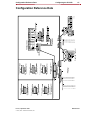
CONFIGURATION REFERENCE DATA . . . . . . . . . . . . . . . . . . . . . . . . . . . . . . . . . . . . . . . . . . . . . . . . . . . . . . . . . . . 41
CONNECTOR TYPE . . . . . . . . . . . . . . . . . . . . . . . . . . . . . . . . . . . . . . . . . . . . . . . . . . . . . . . . . . . . . . . . . . . . . . . . . . 44
CONNECTOR PINOUTS . . . . . . . . . . . . . . . . . . . . . . . . . . . . . . . . . . . . . . . . . . . . . . . . . . . . . . . . . . . . . . . . . . 45
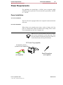
POWER REQUIREMENTS . . . . . . . . . . . . . . . . . . . . . . . . . . . . . . . . . . . . . . . . . . . . . . . . . . . . . . . . . . . . . . . . . . . . . . 47
POWER INSTALLATION . . . . . . . . . . . . . . . . . . . . . . . . . . . . . . . . . . . . . . . . . . . . . . . . . . . . . . . . . . . . . . . . . . 47
ALARM. . . . . . . . . . . . . . . . . . . . . . . . . . . . . . . . . . . . . . . . . . . . . . . . . . . . . . . . . . . . . . . . . . . . . . . . . . . . . . . . 48
GROUNDING REQUIREMENTS . . . . . . . . . . . . . . . . . . . . . . . . . . . . . . . . . . . . . . . . . . . . . . . . . . . . . . . . . . . . 48
CABLING . . . . . . . . . . . . . . . . . . . . . . . . . . . . . . . . . . . . . . . . . . . . . . . . . . . . . . . . . . . . . . . . . . . . . . . . . . . . . . 49
TESTING . . . . . . . . . . . . . . . . . . . . . . . . . . . . . . . . . . . . . . . . . . . . . . . . . . . . . . . . . . . . . . . . . . . . . . . . . . . . . . . . . . . . 52
SLIDE SWITCH SETTINGS . . . . . . . . . . . . . . . . . . . . . . . . . . . . . . . . . . . . . . . . . . . . . . . . . . . . . . . . . . . . . . . . 52
T1 LOOPBACK . . . . . . . . . . . . . . . . . . . . . . . . . . . . . . . . . . . . . . . . . . . . . . . . . . . . . . . . . . . . . . . . . . . . . . . . . 55
DATA PORT 1 AND 2 LOOPBACK. . . . . . . . . . . . . . . . . . . . . . . . . . . . . . . . . . . . . . . . . . . . . . . . . . . . . . . . . . 59
LED INDICATORS . . . . . . . . . . . . . . . . . . . . . . . . . . . . . . . . . . . . . . . . . . . . . . . . . . . . . . . . . . . . . . . . . . . . . . . . . . . . 61
Issue 1, September 1998
© 1998, ADC Telecommunications, Inc.
ADCP-62-023
vi
Front Matter
TABLE OF CONTENTS
Content
Page
WARRANTY/SOFTWARE. . . . . . . . . . . . . . . . . . . . . . . . . . . . . . . . . . . . . . . . . . . . . . . . . . . . . . . . . . . . . . . . . . . . . . . 69
REPAIR/ADVANCE REPLACEMENT POLICY . . . . . . . . . . . . . . . . . . . . . . . . . . . . . . . . . . . . . . . . . . . . . . . . . . . . . . 69
REPAIR CHARGES . . . . . . . . . . . . . . . . . . . . . . . . . . . . . . . . . . . . . . . . . . . . . . . . . . . . . . . . . . . . . . . . . . . . . . . . . . . 69
REPLACEMENT/SPARE PRODUCTS . . . . . . . . . . . . . . . . . . . . . . . . . . . . . . . . . . . . . . . . . . . . . . . . . . . . . . . . . . . . . 70
RETURNED MATERIAL . . . . . . . . . . . . . . . . . . . . . . . . . . . . . . . . . . . . . . . . . . . . . . . . . . . . . . . . . . . . . . . . . . . . . . . . 70
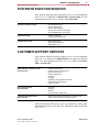
SYSTEM INTEGRATION SERVICES . . . . . . . . . . . . . . . . . . . . . . . . . . . . . . . . . . . . . . . . . . . . . . . . . . . . . . . . . . . . . . 71
CUSTOMER SUPPORT SERVICES . . . . . . . . . . . . . . . . . . . . . . . . . . . . . . . . . . . . . . . . . . . . . . . . . . . . . . . . . . . . . . . 71
ADCP-62-023
Issue 1, September 1998
© 1998, ADC Telecommunications, Inc.
Front Matter
vii
IMPORTANT SAFETY INSTRUCTIONS
Read and follow all warning notices and instructions marked on the product or included in this guide.
1.
This product is intended to be used with a three-wire grounding type plug. This is a safety feature.
Equipment grounding is vital to ensure safe operation. Do not defeat the purpose of the grounding
type plug by modifying the plug or using an adapter.
2.
Prior to installation use an outlet tester or a voltmeter to check the AC receptacle for the presence of
earth ground. If the receptacle is not properly grounded, the installation must not continue until a
qualified electrician has corrected the problem. In addition, a connection for earth or safety grounding
is provided on the chassis. It is a #6 threaded stud located next to the AC inlet receptacle.
3.
Slots and openings in the ICX-250 are provided for ventilation. To ensure reliable operation of the
product and to protect if from overheating, these slots and openings must not be blocked or covered.
4.
DO NOT allow anything to rest on the power cord and do not locate the product where persons could
step or walk on the power cord.
5.
DO NOT attempt to service this product yourself, as opening or removing covers may expose you
to dangerous high voltage points or other risks. Refer all servicing to qualified service personnel.
6.
Special cables, which may be required by the regulatory inspection authority for the installation site,
are the responsibility of the customer.
7.
When installed in the final configuration, the product must comply with the applicable Safety Standards
and regulatory requirements of the country in which it is installed. If necessary, consult with the
appropriate regulatory agencies and inspection authorities to ensure compliance.
8.
A rare phenomenon can create a voltage potential between the earth grounds of two or more buildings.
If products installed in separate buildings are interconnected, the voltage potential may cause a
hazardous condition. Consult a qualified electrical consultant to determine whether or not this
phenomenon exists and, if necessary, implement corrective action prior to interconnecting the product.
INDUSTRY CANADA REQUIREMENTS
NOTICE: The Canadian Industry Canada label identifies certified equipment. This certification
means that the equipment meets certain telecommunications network protective, operational and
safety requirements. The Department does not guarantee the equipment will operate to the user’s
satisfaction.
Before installing this equipment, users should ensure that it is permissible to be connected to the
facilities of the local telecommunications company. The equipment must also be installed using an
acceptable method of connection. In some cases, the company’s inside wiring associated with a
single line individual service may be extended by means of a certified connector assembly (telephone extension cord). The customer should be aware that compliance with the above conditions
may not prevent degradation of service in some situations.
Repairs to the certified equipment should be made by an authorized Canadian maintenance facility
designated by the supplier. Any repairs or alterations made by the user to this equipment, or equipment malfunctions, may give the telecommunications company cause to request the user to disconnect the equipment.
Users should ensure for their own protection that the electrical ground connections of the power
utility, telephone lines and internal metallic water pipe system, if present, are connected together.
This precaution may be particularly important in rural areas.
Issue 1, September 1998
© 1998, ADC Telecommunications, Inc.
ADCP-62-023
viii
Front Matter
CAUTION: Users should not attempt to make such connections themselves, but should contact
the appropriate electric inspection authority, or electrician, as appropriate.
The Ringer Equivalence Number (REN) assigned to each terminal device denotes the percentage
of the total load to be connected to a telephone loop which is used by the device, to prevent overloading. The termination on a loop may consist of any combination of devices subject only to the
requirement that the total REN of all the devices does not exceed 5. The RInger Equivalence Number of this unit is Not Applicable.
FCC PART 15 INFORMATION
This device has been tested and found to comply with FCC Part 15 “Class A” regulations for digital devices. Operation is subject to the following two conditions: (1) This device may not cause
harmful interference and (2) This device must accept any interference that may cause undesired
operation.
These FCC limits are designed to provide reasonable protection against harmful interference when
the equipment is operated in a commercial environment. This equipment generates, uses, and can
radiate radio frequency energy, and, if not installed and used in accordance with this User Manual,
may cause harmful interference to radio communications. Operation of this equipment in a residential area may cause harmful interference. If this happens, the user would be required to correct
the interference at his own expense.
FCC REGULATORY REQUIREMENTS
Notice to Users of T1 Service
The following instructions are provided to ensure compliance with the Federal Communications
Commission (FCC) Rules, Part 68. FCC Regulartory Number: 1H5USA-32637-DE-N.
1.
Before connecting your unit, you must inform the telephone company of the following information:
Port ID
REN/SOC
FIC
USOC
T1 Line
6.0N
04DU9-BN
RJ48C / Dual Bantam Jacks
T1 Line
6.0N
04DU9-DN
RJ48C / Dual Bantam Jacks
T1 Line
6.0N
04DU9-1KN
RJ48C / Dual Bantam Jacks
T1 Line
6.0N
04DU9-1SN
RJ48C / Dual Bantam Jacks
2.
If the unit appears to be malfunctioning, it should be disconnected from the telephone lines until you
learn if your equipment or the telephone line is the source of the trouble. If your equipment needs repair,
it should not be reconnected until it is repaired.
3.
If the telephone company finds that this equipment is exceeding tolerable parameters, the telephone company
can temporarily disconnect service, although they will attempt to give you advance notice if possible.
4.
Under the FCC Rules, no customer is authorized to repair this equipment. This restriction applies
regardless of whether the equipment is in or out of warranty.
ADCP-62-023
Issue 1, September 1998
© 1998, ADC Telecommunications, Inc.
Front Matter
ix
5.
If the telephone company alters their equipment in a manner that will affect use of this device,
they must give you advance warning so as to give you the opportunity for uninterrupted service.
You will be advised of your right to file a complaint with the FCC.
6.
An affidavit must be completed by the installer.
7.
In the event of equipment malfunction, all repairs should be performed by our Company or an
authorized agent. It is the responsibility of users requiring service to report the need for service
to our Company or to one of our authorized agents.
UL APPROVED
The ICX-250 has been designed and tested in accordance with the requirements of UL1950.
CSA APPROVED
The ICX-250 has been designed and tested in accordance with the requirements of CSA C22.2
No. 950.
Issue 1, September 1998
© 1998, ADC Telecommunications, Inc.
ADCP-62-023
Welcome
1
CHAPTER 1
Welcome
This chapter introduces you to the features and benefits
of ICX-250.
Contents
Unpacking the ICX-250 . . . . . . . . . . . . . 2
Product Overview. . . . . . . . . . . . . . . . . . 3
Issue 1, September 1998
© 1998, ADC Telecommunications, Inc.
ADCP-62-023
2
Welcome
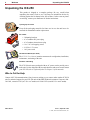
Unpacking the ICX-250
Unpacking the ICX-250
This product is shipped as a complete package. Be very careful when
unpacking the carton. Check to see if all items are included in the box by
checking against the list shown below (Kit of Parts). In the event any items
are missing, contact your distributor for further instructions.
Opening Up the Carton
Keep all the packaging materials for future use in case the unit has to be
returned for maintenance and/or replacement.
Kit of Parts
•
•
•
•
•
•
2 Mounting brackets
A 3-Conductor DC power plug
A 2-Conductor alarm closure plug
6 6 x 5/16” self-tapping screws
4 12/24 x 1/2” screws
1 AC power cord
ICX-250 User Manual (this book)
The IC X -2 50 U ser M an ual contains common tasks: configuration, installation,
maintenance, and testing of the unit.
Hardware and Cabling
The ICX-250 unit comes packaged with an AC power cord to provide power
to the unit. It is also shipped with two angle brackets and screws to rack mount
your ICX-250 (this is explained further in Chapter 2 of this manual).
Who to Call for Help
Contact ADC Telecommunications if any items are missing or you want to order another ICX-250
unit. For technical support for your ICX-250 unit call the BBG Technical Assistance Center at 1-800366-3891, extension 3223 (in U.S.A. or Canada) or 612-946-3223 (outside U.S.A. and Canada).
ADCP-62-023
Issue 1, September 1998
© 1998, ADC Telecommunications, Inc.
Product Overview
Welcome
3
Product Overview
Bundled Service deployment is a snap thanks to the ICX-250 from ADC Telecommunications.
ADCs’ ICX-250 allows cost-effective and quick deployment of analog voice and data services on a
single T1 access trunk.
The ICX-250 sports a sleek, low profile chassis and is configured via DIP switches, eliminating the
need for PC based craft interface and specialized training. LEDs are provided for monitoring the
status of ICX-250 under normal operation as well as under test conditions. Maintenance and
diagnostics are further enhanced via loopbacks and test patterns, all configurable from the DIP
switches. Additionally, network loopbacks can be used to test from a remote office.
ICX-250 addresses access needs for sites requiring economical adaptation of FXS analog voice
based key systems and PBXs to T1 services. ICX-250 supports TR-08 as well as ESF and D4
framing. Additionally, ICX-250 provides two high speed EIA530A/V.35 ports for insertion of
Routers or other data traffic in bundled service arrangements. For sites needing up to 24 analog
lines, with or without data requirements, ADC’s ICX-250 is an ideal solution.
The ICX-250’s primary function is to allow for remote termination of lines from a centrallylocated switch. Data ports are also provided on the unit for those applications where high speed
data deployment would be required.
The ICX-250 product is complimentary to the leading ICX-500 and Integrated Communications
Access server (ICX).
The ICX-250 from ADC Telecommunications - never before have bundled services been so
economical and easy to install and maintain.
Features
• Voice and data channel bank with integral CSU/DSX Interface
• Sleek, low profile, one rack unit (1 RU) chassis
• Choice of 12 or 24 FXS analog voice ports
• Two high speed EIA530A/V.35 data ports
• Extensive diagnostics
• LED status indicators for maintenance
• DIP switch configuration
• TR-08 support
Benefits
• Minimal Installation Costs - DIP switch based configuration simplifies
installation, eliminates need for a computer terminal, and reduces training costs.
• 1 RU design allows easy installation in tight spaces. Rack, wall or desktop
mounting options are available.
• Simplified Maintenance - manual test DIP switches, maintenance test and LED
status indicators, all simplify maintenance operations.
Issue 1, September 1998
© 1998, ADC Telecommunications, Inc.
ADCP-62-023
4
Welcome
Product Overview
TR-08
The TR-TSY-000008 BellcoreTM standard (commonly referred to as TR-08) describes the generic
requirements for interfacing between local digital switches and remote digital terminals via the
SLC 96TM digital loop carrier system.
TR-08 has three operational modes (ICX-250 supports mode I):
• Modes I & III are non-concentrated and provide unique mapping between channel
numbers and DS1 time slots.
• Mode II is concentrated and there are no pre-determined relationships between the
channels and timeslots. This allocation of channels to time slots is made possible by the
exchange of messages between the Local Digital Switch (LDS) and remote terminal (RT).
Although commonly referred to as the TR-08 standard, the RT channel numbering scheme supported
by the ICX-250 unit is described in section 9.9 of the Bellcore publication TR-TSY-000057.
The ICX-250 provides SLC-96 Frame Format and Data Link.
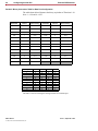
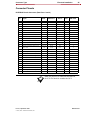
When a T1 port is configured for TR-08 format, the voice channels assigned to this port are identified
by “channel number” (according to the TR-TSY-000008 document), which may be different from
the T1 time slot number. The ICX-250 supports only Group A. The relation between a channel number
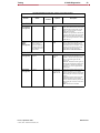
and corresponding slot number for TR-08 is shown in the following table.
Channel Numbers
1
2
3
4
5
6
7
8
9
10
11
12
13
14
15
16
17
18
19
20
21
22
23
24
Time Slots
1
3
5
7
9
11
13
15
17
19
21
23
2
4
6
8
10
12
14
16
18
20
22
24
ADCP-62-023
Issue 1, September 1998
© 1998, ADC Telecommunications, Inc.
Product Overview
Welcome
5
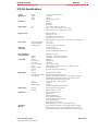
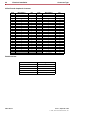
ICX-250 Specifications
Chassis
Specification
Height
Width
Depth
Weight
Installation
Power Supply
Desktop
Wall Mount
Rackmount
AC
DC
Ring Generator
Environment
1.75 inches (with feet 2 inches)
17.25 inches
12 inches
Approximately 10 pounds
120V .6A Max. 60Hz (104 - 140 VAC)
–48V, –24V, or +24V 1.8A Max. (22.5 - 57 VDC)
Integrated AC/DC converter and Ringing Generator
Nominal 50 VRMS
Frequency 20 +/–1 Hz
DC component: –30 volts nominal
Crest factor cf, where 1.2=<cf=<1.6
Ringing Capability: 40 Vrms across 1 REN at the end of a 400 ohms loop.
Operating Temperature
Storage Temperature
Relative Humidity
Regulatory
Compliance
00 C to 400 C
–400 C to 660 C
5 to 85% Humidity, Non-Condensing
FCC Part 15 Class A
UL 1950 and CSA C22.2 950
FCC Part 68 and Industry Canada CS-03
FCC Regulatory #
1H5USA-32637-DE-N
Product Numbers
240212
240224
12 FXS ports, 2 EIA530A/V.35 data ports
24 FXS ports, 2 EIA530A/V.35 data ports
T1 Interface
Physical
Frame Format
Line Code
CSU Line Build Out
(LBO)
DSX Line Length
Clocking
FDL
One RJ48
D4, ESF, TR-08
AMI, B8ZS
0 dB, –7.5 dB, –15.0 dB
0.6 dB at 0-266 ft., 1.8 dB at 266 - 533 ft., 3.0 dB at 533 - 655 ft.
Internal Stratum 4, Line
Per ANSI T1.403 and AT&T TR62411
FXS Interface
Physical
FXS Supervision Mode
FXS Signaling
One 50-pin Female Amphenol
FXS, FXS-DN, FXS-DN-Wink, TR-08
Loop Start, Ground Start, Loop Start w/ forward Disconnect, Ground
Start Immediate, Ground Start Automatic, Universal Voice Grade,
Universal Voice Grade Automatic, Single-Party
–3 dB/–9 dB on Rx, + 3 dB/+9 dB on Tx
600 Ohm
50 Vrms
On hook transmission for Caller ID support
TLP
Impedance
Ringing Voltage
Data Interface
Physical
Data Rate
Two (2) EIA530A/V.35 ports (DB25)
Nx56K, Nx64K (N = 1 to 24)
Diagnostics
Extensive power-up self test
LED Indicators
QRSS Test Pattern on T1
2047 Test Pattern on Data ports
Loopbacks for FXS, T1 and Data ports
CSU Loopback detection
Performance statistics over FDL
Bantam jacks for in-session T1 monitoring and line testing
DIP Switch
Settings
FXS, T1, Data port Loopbacks, CSU Loopback Detection, Clocking,
T1 Frame Format, T1 Line Code, T1 Line Build Out, FXS TLP, FXS
Supervision, FXS Signaling, Trunk Conditioning, Test Patterns, Data rate.
Issue 1, September 1998
© 1998, ADC Telecommunications, Inc.
ADCP-62-023
System Basics
CHAPTER
7
2
System Basics
This chapter gives you quick, simple instructions to get you up
and running. You will also learn how to install and mount the
ICX-250 unit.
Contents
Installing the ICX-250 . . . . . . . . . . . . . . . 8
The ICX-250 Unit . . . . . . . . . . . . . . . . . . 13
Issue 1, September 1998
© 1998, ADC Telecommunications, Inc.
ADCP-62-023
8
System Basics
Installing the ICX-250
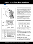
Installing the ICX-250
The ICX-250 unit can be installed in a rack, on a desktop or attached to a
wall using appropriate wall anchors and brackets. It is necessary to read
the information that follows to ensure proper reliability of unit.
Choosing a Site for the ICX-250
When choosing a site for your ICX-250 unit make sure that the
instructions on installing the unit are followed. Provide adequate
ventilation and ample room for cable routing.
Temperature Specifications
Shipping and storage –40o C to +66o C
Operating temperature range 0o C to +40o C
Relative Humidity 5 to 85% Non-Condensing
Note: The ICX-250 is equipped with a fan to ensure
proper cooling and reliability. In the event that the
installation environment temperature exceeds the
standards above, it is recommended that adjustments
be made. Improper operation outside of these temperatures may
result in performance degradation.
Precautionary Procedures
There are several precautions to take before installing and/or servicing the
ICX-250 unit.
CAUTION
Never install telephone wiring during a lightning
storm.
Never install telephone jacks in wet locations unless the jack is
specifically designed for this purpose ONLY.
Never touch uninsulated telephone wires or terminals unless the
telephone line has been disconnected at the network interface.
Use CAUTION when installing or modifying telephone lines.
Never attempt to service this product unless you are an
authorized service technician. Doing so can result in injury or
damage to the unit and void all warranties.
ADCP-62-023
Issue 1, September 1998
© 1998, ADC Telecommunications, Inc.
Installing the ICX-250
System Basics
9
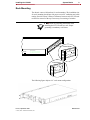
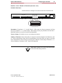
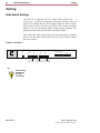
Rack Mounting
The chassis comes with brackets for rack mounting. The installation site
for rack mounting should provide proper room for ventilation and cable
routing. Provide at least 2 inches of clearance between each ICX-250 unit
to allow for removal of the top if necessary for resetting of switches.
1RWH Check all grounding instructions when
installing the ICX-250 unit in a rack. Proper
grounding is mandatory at all times.
Center Mount
Data Loop 2
Lcl. Off Net.
FXS Channel Status
1 3 5 7 9 11 13 15 17 19 21 23
2 4 6 8 10 12 14 16 18 20 22 24
Flush Mount
The following figure depicts a 19” rack mount configuration.
Issue 1, September 1998
© 1998, ADC Telecommunications, Inc.
ADCP-62-023
10
System Basics
Installing the ICX-250
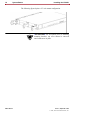
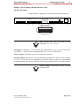
The following figure depicts a 23” rack mount configuration.
!!ATTENTION!! Set all options prior to installing
mounting brackets, top cover cannot be removed
once brackets are in place.
ADCP-62-023
Issue 1, September 1998
© 1998, ADC Telecommunications, Inc.
Installing the ICX-250
System Basics
11
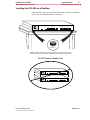
Locating the ICX-250 on a Desktop
Test Pattern
Test Pattern
T1 Loop
T1 Status
T1 Test
Self Check
Each unit can be easily set on top of a desk or table. A stable environment
is necessary for peak performance of each unit.
FXS Status Channel
1 3 5 7 9 11 13 15 17 19 21 23
ICX-250
2 4 6 8 10 12 14 16 18 20 22 24
(Four)
Rubber Feet
Rubber feet are necessary for proper ventilation and air flow of the unit
when mounted on a flat surface. Removing them may damage the unit.
Test Pattern
Test Pattern
T1 Loop
T1 Status
T1 Test
Self Check
DO NOT Remove Rubber Feet
ICX-250
Test Pattern
Test Pattern
T1 Loop
T1 Status
T1 Test
2 4 6 8 10 12 14 16 18 20 22 24
Self Check
ICX-250
FXS Status Channel
1 3 5 7 9 11 13 15 17 19 21 23
FXS Status Channel
1 3 5 7 9 11 13 15 17 19 21 23
2 4 6 8 10 12 14 16 18 20 22 24
11263-A
Issue 1, September 1998
© 1998, ADC Telecommunications, Inc.
ADCP-62-023
12
System Basics
Installing the ICX-250
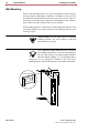
Wall Mounting
Prior to wall mounting check to see if the environment is stable and free
from any extreme temperatures, humidity or vibrations of any sort. The
unit should be mounted with the fan to the top with at least 2 inches of
clear space on the sides, above, and below for adequate air flow. Allow at
least 6 inches for cable clearance and access to switches.
When attaching unit(s) to a wall make sure that appropriate fasteners such
as masonry anchors, heavy duty wood screws or expansion bolts are used
for heavy objects.
!!ATTENTION!! Set all options prior to installing
mounting brackets, top cover cannot be removed
once brackets are in place.
Note: Additional support hardware may be necessary
(not included with unit) to secure the unit properly to
the wall. If the surface is not solid enough to hold the
unit and attached cabling, it is recommended that a
small piece of 3/4” plywood be fastened to the wall before
attaching the unit. This will help ensure a more stable environment.
A N G LE BR A C K E T
W all
ADCP-62-023
Issue 1, September 1998
© 1998, ADC Telecommunications, Inc.
The ICX-250 Unit
System Basics
13
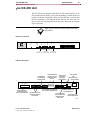
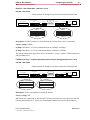
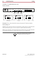
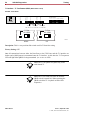
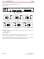
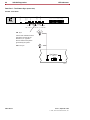
The ICX-250 Unit
The ICX-250 comes equipped with either 12 FXS (model 240212) or 24
FXS (model 240224) analog voice ports depending on which model you
purchase. Each unit is designed to allow easy accessibility to switches and
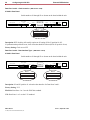
electrical connectors. The diagrams below illustrate the front and rear
layout of the unit. The diagram on the next page illustrates the internal
layout of the unit.
Note: The 12 FXS or 24 FXS models are not field
upgradeable.
Test Pattern
Test Pattern
T1 Loop
T1 Status
T1 Test
Self Check
ICX-250 - Front Panel
FXS Status Channel
1 3 5 7 9 11 13 15 17 19 21 23
ICX-250
2 4 6 8 10 12 14 16 18 20 22 24
Off / QRSS
11261-A
1 / Off / 2
T1 Loop
Data Loop 1 Data Loop 2
Net. / Off / Lcl. Lcl. / Off / Net. Lcl. / Off / Net.
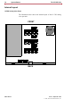
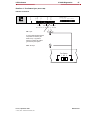
ICX-250 - Rear Panel
ALARM RELAY
FOR EXTERNAL
ALARM SYSTEM
TWO DB25 FEMALE
CONNECTORS FOR
DATA PORT 1 AND 2
SIGNALS
DIP SWITCHES
USED FOR T1
INTERFACE
CONFIGURATION
Data 1
FXS Loop Pairs
1
FXS Loopback
12 13
24 Alm.
Data 1
Data 2
DUAL BANTAM
JACK
(MONITOR JACKS)
EARTH GROUND
T1
Data 2
T1
T1 Line Rx 24/48 VDC
+–G
Tx
120 VAC–.6A 60Hz
25 PAIR AMPHENOL
CONNECTOR FOR 24
FXS TIP AND RING PAIRS
DIP SWITCHES USED FOR DATA
PORT 1 AND 2 CONFIGURATION
DIP SWITCHES TO SET
LOOPBACK FOR EACH
FXS CHANNEL
Issue 1, September 1998
© 1998, ADC Telecommunications, Inc.
TERMINAL BLOCK FOR
DC POWER SUPPLY
RJ48 CONNECTOR
FOR TRANSMIT AND
RECEIVE TIP AND
RING PAIRS
POWER INPUT FOR
120 VAC RECEPTACLE
11264-A
ADCP-62-023
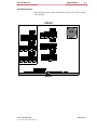
14
System Basics
The ICX-250 Unit
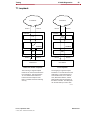
Internal Layout
12 FXS Analog Voice Ports
The illustration below shows the internal layout of the 12 FXS analog
voice port unit.
FRONT
ON
DIP
1 2 3 4 5 6 7 8
S16
ON
FAN
DIP
1 2 3 4 5 6 7 8
S15
ON
DIP
1 2 3 4 5 6 7 8
S14
S7
S6
ON
DIP
1 2 3 4 5 6 7 8
S2
DIP
1 2 3 4 5 6 7 8
S1
ON
S3
S4
S5
BACK
ADCP-62-023
Issue 1, September 1998
© 1998, ADC Telecommunications, Inc.
The ICX-250 Unit
System Basics
15
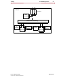
24 FXS Analog Ports
The illustration below shows the internal layout of the 24 FXS analog
voice port unit.
FRONT
ON
DIP
1 2 3 4 5 6 7 8
DIP
S16
ON
FAN
1 2 3 4 5 6 7 8
S19
ON
DIP
1 2 3 4 5 6 7 8
S15
ON
DIP
1 2 3 4 5 6 7 8
S18
ON
DIP
1 2 3 4 5 6 7 8
DIP
S14
ON
1 2 3 4 5 6 7 8
S17
S7
S6
ON
DIP
1 2 3 4 5 6 7 8
S2
DIP
1 2 3 4 5 6 7 8
S1
ON
S3
S4
S5
BACK
Issue 1, September 1998
© 1998, ADC Telecommunications, Inc.
ADCP-62-023
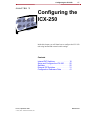
Configuring the ICX-250
CHAPTER
17
3
Configuring the
ICX-250
Inside this chapter you will learn how to configure the ICX-250
unit using internal and external switch settings.
Contents
Internal DIP Switches . . . . . . . . . . . . . . . 18
Setup and Configure the ICX-250 . . . . . 20
Switches . . . . . . . . . . . . . . . . . . . . . . . . . 20
External DIP Switches . . . . . . . . . . . . . . 31
Configuration Reference Data . . . . . . . . 41
Issue 1, September 1998
© 1998, ADC Telecommunications, Inc.
ADCP-62-023
18
Configuring the ICX-250
Internal DIP Switches
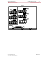
Internal DIP Switches
The ICX-250 comes equipped with either 12 FXS or 24 FXS analog voice
ports depending on which model you purchase. For illustration purposes
the 24 FXS port model is shown. There are a total of eight internal DIP
switches (five on the main circuit board, and three on the auxiliary
board).
Note: The individual switches on each switch
assembly operate independently of one another.
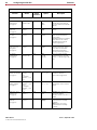
DIP Switch Settings
Locate the DIP switch internally that describes the function you wish to
effect. The top cover of the unit displays the configurable options. Use the
tip of a small object to change the switch settings. The switches will glide
easily into place.
CAUTION
Access to the internal switches is accomplished by
opening the case. Use care when opening the case to
avoid damaging the internal components.
TIP
Switch setting
changes will
take effect
immediately.
ADCP-62-023
© 1998, ADC Telecommunications, Inc.
Issue 1, September 1998
Internal DIP Switches
Configuring the ICX-250
19
FRONT
ON
DIP
S16
1 2 3 4 5 6 7 8
S19
DIP
S16
ON
1 2 3 4 5 6 7 8
S19
ON
DIP
S15
1 2 3 4 5 6 7 8
S18
DIP
S15
ON
1 2 3 4 5 6 7 8
S18
ON
DIP
S14
1 2 3 4 5 6 7 8
DIP
S14
S17
ON
1 2 3 4 5 6 7 8
S17
S7
S6
ON
DIP
1 2 3 4 5 6 7 8
S6
S2
DIP
1 2 3 4 5 6 7 8
S1
ON
S7
S3
S4
S5
BACK
Issue 1, September 1998
© 1998, ADC Telecommunications, Inc.
ADCP-62-023
20
Configuring the ICX-250
Setup and Configure the ICX-250
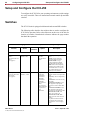
Setup and Configure the ICX-250
To configure the ICX-250 for your operating environment, switch settings
are easily accessible. There are internal and external control dip and slide
switches.
Switches
The ICX-250 unit is equipped with internal and external DIP switches.
The following table describes the switches that are used to configure the
ICX-250 for operation. Refer to the silkscreen on the cover of the unit for
location of switches. Parenthetical references indicate the page number
that detail the operation.
The bold highlighted selection under “Options” is the Factory Setting.
Function
Switch
Switch
Location
Option
Description
FXS PORTS:
FXS Supervision
Mode
(for entire bank of 12
lines)
(see page 23)
S6, S7
positions 1 and 2
Internal
FXS
FXS-DN
FXS-DN-Wink
TR-08
FXS: Foreign Exchange Subscriber.
FXS-DN: Foreign Exchange
Subscriber-Defined Network.
FXS-DN-WINK: Foreign
Exchange Subscriber-Defined.
Network-Wink Start Operation.
TR-08: Frame Format Signaling
and Data Link as outlined in TRTSY-000008 Mode 1 for circuits
using AT&T Subscriber Loop
Carriers (SLC-96) facilities.
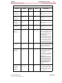
FXS Supervision
Type (for entire bank
of 12 lines)
(see page 24)
S6, S7
positions 3, 4 and 5
Internal
Loop Start
Single Party
Ground Start
Ground Start
Automatic
Ground Start
Immediate
Universal Voice
Grade
Universal Voice
Grade Automatic
Loop Start-Forward
Disconnect
Loop Start: Used with traditional
telephone stations and simple PBX
trunks.
Single Party: SLC-96 Single Party
Service.
Ground Start: Used with two-way
PBX trunks.
Ground Start Automatic: Used
with equipment requiring fastresponse time to the central office
(CO).
Ground Start Immediate: Used
with equipment requiring fastresponse time to the station or PBX.
Universal Voice Grade: Toll
quality voice for SLC-96.
Universal Voice Grade Automatic: Used with some non-Bell
switches.
Loop Start-Forward Disconnect:
Provides disconnect when FXS
is connected to voice messaging
system.
ADCP-62-023
© 1998, ADC Telecommunications, Inc.
Issue 1, September 1998
Switches
Configuring the ICX-250
21
The bold highlighted selection under “Options” is the Factory Setting.
Function
Switch
Switch
Location
Option
Description
FXS Ports
Transmit
for 12 port model
(see page 26)
S14, S15, S16
positions 2, 4, 6
and 8
Internal
3 dB
9 dB
3 dB: Transmit path attenuated by
3 dB (+/– .5).
9 dB: Transmit path attenuated by
9 dB (+/– .5).
FXS Ports
Receive
for 12 port model
(see page 26)
S14, S15, S16
positions 1, 3, 5
and 7
Internal
3 dB
9 dB
3 dB: Receive path attenuated by
3 dB (+/– .5).
9 dB: Receive path attenuated by
9 dB (+/– .5).
FXS Ports
Transmit
for 24 port model
(see page 26)
S17, S18, S19
positions 2, 4, 6
and 8
Internal
3 dB
9 dB
3 dB: Transmit path attenuated by
3 dB (+/– .5).
9 dB: Transmit path attenuated by
9 dB (+/–.5).
FXS Ports Receive
for 24 port model
(see page 26)
S17, S18, S19
positions 1, 3, 5
and 7
Internal
3 dB
9 dB
3 dB: Receive path attenuated by
3 dB (+/– .5).
9 dB: Receive path attenuated by
9 dB (+/– .5).
Trunk Conditioning
(per group of 12
lines)
(see page 28)
S6, S7
position 6
Internal
Idle
Idle Imm./Busy
Idle: In the event of an alarm condition in the T1 connection to the network, the FXS Ports will be put into
the idle state immediately and
remain in this condition until the T1
has been restored.
Idle Immediate/Busy: In the event
of an alarm condition in the T1 connection between the ICX-250 and
the network, the FXS Ports will be
put into the Idle state immediately
for 3 seconds and then put in the
Busy state and remain in this condition until the T1 has been restored.
FXS Ringback Tone
(see page 29)
S6-S7
position 7
Internal
On
Off
On: Ringback tones will be sent
on the corresponding DS0’s for the
duration of ringing on the line.
Off: Ringback provided by PBX
or Switch.
FXS Timeslot
Assignment
(see page 30)
S7 Only
position 8
Internal
Off
Swap
Off: FXS Ports 1-12 are mapped
onto T1 timeslots 1-12 and FXS
Ports 13-24 are mapped onto T1
timeslots 13-24.
Swap: FXS Ports 1-12 are mapped
onto T1 timeslots 13-24 and FXS
Ports 13-24 are mapped onto T1
timeslots 1-12.
Depending on the services provided by your carrier for voice
and data, you may need to reassign the FXS timeslots of the 12
FXS port model. Timeslots 13 to
24 will be assigned in order to
allocate data to the lower
timeslots.
FXS Ports
Loopback Operation
and/or Channel
Unassigned
(per line)
(see page 39)
S4-S5
S5 1-12 = 1-12
S4 1-12 = 13-24
Back
On
Off
On: Breaks the connections to
and from the FXS and loops the
receive data back onto the transmit
path towards the T1. In the case
of unassigned channels, provides
an idle termination.
Issue 1, September 1998
© 1998, ADC Telecommunications, Inc.
ADCP-62-023
22
Configuring the ICX-250
Switches
The bold highlighted selection under “Options” is the Factory Setting.
Function
Switch
Switch
Location
Option
Description
T1 INTERFACE:
T1 Interface
Frame Format
(see page 32)
S1
positions 1 and 2
Back
D4 (SF)
ESF
TR-08
Selects the T1 frame format and
data link format to be either D4
(SF), ESF, or TR-08. (No data link
with D4).
T1 Interface
Line Code
(see page 32)
S1
position 3
Back
AMI
B8ZS
Selects the line code on the T1
interface.
T1 Interface
T1 Clock
(see page 33)
S1
position 4
Back
Line
Internal
Line: Clock for the T1 interface
will be recovered from the line
(receive signal).
Internal: Clock for the T1 interface
will be taken from an on-board
1.544 MHz clock meeting the
Stratum 4 requirements.
T1 Interface
CSU Loop Code
Recognition
(see page 34)
S1
position 5
Back
Accept
Ignore
Accept: ICX-250 will respond to
network generated loop requests
that are received over the FDL.
Ignore: ICX-250 will ignore
network generated loop requests.
T1 Interface
Line Build Out
(see page 34)
S1
positions 6 and 7
Back
0 dB
–7.5 dB
–15.0 dB
Selects one of three line build
out options for short (–15.0 dB),
medium (–7.5 dB) and long (0 dB)
loops.
DATA PORTS:
Data Ports 1 and 2
Number of Timeslots
(see page 35)
S2 - dataport 2
positions 1, 2, 3, 4
and 5
S3 - dataport 1
positions 1, 2, 3, 4
and 5
Back
0
1, 2, 3, ....24
Selects the number of timeslots
that data from Data Port 1
and/or 2 will be mapped onto.
Data Ports 1 and 2
Starting Timeslot
(see page 37)
S2 - dataport 2
positions 6, 7, 8, 9
and 10
S3 - dataport 1
positions 6, 7, 8, 9
and 10
Back
0
1, 2, 3, ....24
Selects first T1 timeslot that data
from Data Port 1 and/or 2 will be
mapped.
Data Ports 1 and 2
Interface Type
(see page 38)
S2, S3
position 11
Back
EIA530A
V.35
EIA530A: Ports 1 and/or 2 use
the EIA530A standard.
V.35: Ports 1 and/or 2 use the V.35
standard.
Data Ports 1 and 2
Data Rate
(see page 39)
S2, S3
position 12
Back
64 Kbps
56 Kbps
64Kbps: Ports 1 or 2 receive
and transmit data at a multiple
of 64 Kbps.
56Kbps: Ports 1 or 2 receive
and transmit data at a multiple
of 56 Kbps.
ADCP-62-023
© 1998, ADC Telecommunications, Inc.
Issue 1, September 1998
Switches
Configuring the ICX-250
23
Note: The function and speed of Data Ports 1 and 2
are independent of each other. This allows one to
operate as EIA530A while the other operates as a
V.35 interface. The speeds can also be set as 56K on
one port and 64K on the other.
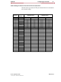
FXS Supervision - Mode (DIP switches - internal)
FRONT
ON
DIP
S16
1 2 3 4 5 6 7 8
S19
DIP
S16
ON
1 2 3 4 5 6 7 8
S19
ON
DIP
S15
1 2 3 4 5 6 7 8
S18
DIP
S15
ON
1 2 3 4 5 6 7 8
S18
ON
DIP
S14
1 2 3 4 5 6 7 8
DIP
S14
S17
ON
1 2 3 4 5 6 7 8
S17
see FXS Supervision Table
S7
S6
ON
DIP
1 2 3 4 5 6 7 8
S6
S2
DIP
1 2 3 4 5 6 7 8
S1
ON
S7
S3
S4
S5
BACK
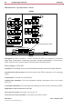
Description: S6 and S7 positions 1 and 2 select the FXS Mode. Options are: FXS, FXS-DN,
FXS-DN-WINK, and TR-08.
Factory Setting: FXS
FXS: Foreign Exchange Subscriber.
FXS-DN: Foreign Exchange Subscriber-Defined Network.
FXS-DN-WINK: Foreign Exchange Subscriber-Defined Network-Wink Start Operation.
TR-08: Signaling as outlined in TR-TSY-000008 Mode 1 for circuits using AT&T Subscriber
Loop Carriers (SLC-96) facilities.
Issue 1, September 1998
© 1998, ADC Telecommunications, Inc.
ADCP-62-023
24
Configuring the ICX-250
Switches
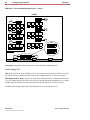
FXS Supervision - Type (DIP switches - internal)
FRONT
ON
DIP
S16
1 2 3 4 5 6 7 8
S19
DIP
S16
ON
1 2 3 4 5 6 7 8
S19
ON
DIP
S15
1 2 3 4 5 6 7 8
S18
S15
ON
DIP
1 2 3 4 5 6 7 8
S18
ON
DIP
S14
1 2 3 4 5 6 7 8
DIP
S14
S17
ON
1 2 3 4 5 6 7 8
S17
see FXS Supervision Table
S7
S6
ON
DIP
S6
1 2 3 4 5 6 7 8
S2
DIP
1 2 3 4 5 6 7 8
S1
ON
S7
S3
S4
S5
BACK
Description: S6 and S7 positions 3, 4 and 5 determine the FXS type. Options are: Loop Start,
Single Party, Ground Start, Ground Start Automatic, Ground Start Immediate, Universal Voice
Grade, Universal Voice Grade Automatic and Loop Start Forward Disconnect.
Factory Setting: LOOP START
Loop Start: Tip and Ring closure used with traditional telephone stations and simple PBX lines.
Loop Start-Forward Disconnect: Provides disconnect when FXS is connected to voice messaging
system.
Ground Start: Used with two-way PBX lines.
Ground Start Automatic: Used with equipment requiring fast-response time to the central
office (CO).
Ground Start Immediate: Used with equipment requiring fast-response time to the station or PBX.
Single Party: Single Part Service for SLC-96.
Universal Voice Grade: Toll quality voice for SLC-96.
Universal Voice Grade Automatic: Used with some non-bell switches.
ADCP-62-023
© 1998, ADC Telecommunications, Inc.
Issue 1, September 1998
Switches
Configuring the ICX-250
25
!!ATTENTION!! Changing the Supervision type
switches will result in all FXS calls on the affected 12
FXS line group to be reset to the idle state each time a
DIP switch setting is changed. This means any active
calls in that FXS line group will be dropped.
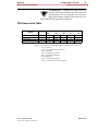
FXS Supervision Table
(Mode)
1, 2
000
001
3, 4, 5 (Type)
100
101
110
FXS
00
LS
LS-fd
GS
GSa
GSi
FXS-DN
01
LS
LS-fd
GS
GSa
GSi
FXS-DN-WINK
10
LS
LS-fd
GS
GSa
GSi
TR-08
11
SP
---
UVG
UVGa
---
Legend: (e.g. S1 position 5 = 01001 means Mode = FXS-DN / Type = LS-fd)
LS = Loop Start
LS-fd = Loop Start-Forward Disconnect
GS = Ground Start
GSa = Ground Start Automatic
GSi = Ground Start Immediate
SP = Single Party
UVG = Universal Voice Grade
UVGa = Universal Voice Grade Automatic
Issue 1, September 1998
© 1998, ADC Telecommunications, Inc.
ADCP-62-023
26
Configuring the ICX-250
Switches
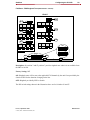
FXS Ports (per line) - Transmit / Receive (DIP switch - internal)
FRONT
ON
DIP
S16
1 2 3 4 5 6 7 8
S19
DIP
S16
ON
1 2 3 4 5 6 7 8
S19
ON
DIP
S15
1 2 3 4 5 6 7 8
S18
DIP
S15
ON
1 2 3 4 5 6 7 8
S18
ON
ON
DIP
S14
S14
S17
DIP
1 2 3 4 5 6 7 8
1 2 3 4 5 6 7 8
S17
4
3
FXS Ports
2
9 dB ON
1
DIP
Receive
Attenuation
(or Loss)
3 dB 1 2 3 4 5 6 7 8
S7
1 2 3 4 5 6 7 8
ON
DIP
1 2 3 4 5 6 7 8
4
S6
S2
DIP
3
2 1
FXS Ports
Transmit
Loss
S1
S7
S6
ON
S3
S4
S5
BACK
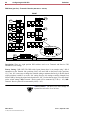
Description: These are eight position DIP switches used to set Transmit and Receive FXS
attenuation (TLP Setting).
Factory Setting: 3 dB (OFF) The DIP switch layout shown above is an example using 3 dB of
attenuation on the Transmit side (positions 2,4,6,8 off) and 9 dB on the Receive side (positions
1,3,5,7 on). If it is necessary to change the Transmit setting to attenuate the line by 9 dB, the related
switch position(s) would be set to the “On” setting. Receive side settings would be changed from
9 dB to 3 dB by moving the related switch position to “Off.” See the chart on page 27 for more detail
on the switch settings. 3dB: Transmit / Receive path will be attenuated by 3 dB (+/– 0.5). 9dB:
Transmit / Receive path will be attenuated by 9 dB (+/–0.5).
!!ATTENTION!! The above FXS Port settings are
repeated for each of the 12 or 24 lines.
ADCP-62-023
© 1998, ADC Telecommunications, Inc.
Issue 1, September 1998
Switches
Configuring the ICX-250
27
Switch Settings for FXS Port Transmit and Receive Attenuation
The table below represents the FXS port transmit and receive attenuation
(loss) control settings.
FXS Port
Switch
Number
1
S14
3 dB Attenuation
9 dB Attenuation
Transmit
Receive
Transmit
Receive
8 = OFF
7 = OFF
8 = ON
7 = ON
2
6 = OFF
5 = OFF
6 = ON
5 = ON
3
4 = OFF
3 = OFF
4 = ON
3 = ON
4
2 = OFF
1 = OFF
2 = ON
1 = ON
8 = OFF
7 = OFF
8 = ON
7 = ON
6
6 = OFF
5 = OFF
6 = ON
5 = ON
7
4 = OFF
3 = OFF
4 = ON
3 = ON
8
2 = OFF
1 = OFF
2 = ON
1 = ON
8 = OFF
7 = OFF
8 = ON
7 = ON
5
9
S15
S16
10
6 = OFF
5 = OFF
6 = ON
5 = ON
11
4 = OFF
3 = OFF
4 = ON
3 = ON
12
2 = OFF
1 = OFF
2 = ON
1 = ON
8 = OFF
7 = OFF
8 = ON
7 = ON
14
6 = OFF
5 = OFF
6 = ON
5 = ON
15
4 = OFF
3 = OFF
4 = ON
3 = ON
16
2 = OFF
1 = OFF
2 = ON
1 = ON
8 = OFF
7 = OFF
8 = ON
7 = ON
18
6 = OFF
5 = OFF
6 = ON
5 = ON
19
4 = OFF
3 = OFF
4 = ON
3 = ON
20
2 = OFF
1 = OFF
2 = ON
1 = ON
8 = OFF
7 = OFF
8 = ON
7 = ON
22
6 = OFF
5 = OFF
6 = ON
5 = ON
23
4 = OFF
3 = OFF
4 = ON
3 = ON
24
2 = OFF
1 = OFF
2 = ON
1 = ON
13
17
21
S17
S18
S19
Issue 1, September 1998
© 1998, ADC Telecommunications, Inc.
ADCP-62-023
28
Configuring the ICX-250
Switches
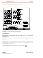
FXS Ports - Trunk Conditioning (DIP switches - internal)
FRONT
ON
DIP
S16
1 2 3 4 5 6 7 8
DIP
S16
ON
S19
1 2 3 4 5 6 7 8
S19
ON
DIP
S15
1 2 3 4 5 6 7 8
S18
S15
ON
DIP
1 2 3 4 5 6 7 8
S18
ON
ON
DIP
S14
S14
S17
DIP
1 2 3 4 5 6 7 8
IDLE
1 2 3 4 5 6 7 8
S17
ON
DIP
1 2 3 4 5 6 7 8
ON
DIP
1 2 3 4 5 6 7 8
S7
1 2 3 4 5 6 7 8
ON
DIP
1 2 3 4 5 6 7 8
S6
S2
DIP
S1
S7
IDLE/BUSY
S6
ON
S3
S4
S5
BACK
Description: S6 position 6 and S7 position 6 selects the trunk conditioning state.
Factory Setting: IDLE
Idle: In the event of an alarm condition in the T1 connection to the network, the FXS Ports will be
put into the idle state immediately and remain in this condition until the T1 has been restored.
Idle Immediate/Busy Delay: In the event of an alarm condition in the T1 connection between the
ICX-250 and the network, the FXS Ports will be put into the Idle state immediately for 3 seconds
and then put into the Busy state and remain in this condition until the T1 has been restored.
The DIP switch settings shown in the illustration above are for Switch S6 and S7.
ADCP-62-023
© 1998, ADC Telecommunications, Inc.
Issue 1, September 1998
Switches
Configuring the ICX-250
29
FXS Ports - FXS Ringback Tone (DIP switches - internal)
FRONT
ON
DIP
S16
1 2 3 4 5 6 7 8
DIP
S16
ON
S19
1 2 3 4 5 6 7 8
S19
ON
DIP
S15
1 2 3 4 5 6 7 8
S18
S15
ON
DIP
1 2 3 4 5 6 7 8
S18
ON
ON
DIP
S14
S14
S17
DIP
1 2 3 4 5 6 7 8
1 2 3 4 5 6 7 8
S17
ON
ON
DIP
1 2 3 4 5 6 7 8
ON
1 2 3 4 5 6 7 8
S7
S6
ON
DIP
S6
1 2 3 4 5 6 7 8
S2
DIP
1 2 3 4 5 6 7 8
OFF
S1
ON
S7
DIP
S3
S4
S5
BACK
Description: S6 position 7 and S7 position 7 provides ringback tone when it is not available from
the PBX or Switch.
Factory Setting: OFF
ON: Ringback tones will be sent to the applicable FXS channels by the unit if not provided by the
Switch or PBX for the duration of ringing on the line.
OFF: Ringback provided by PBX or Switch.
The DIP switch settings shown in the illustration above are for Switches S6 and S7.
Issue 1, September 1998
© 1998, ADC Telecommunications, Inc.
ADCP-62-023
30
Configuring the ICX-250
Switches
FXS Ports - FXS Time Slot Assignment (DIP switch - internal)
FRONT
ON
DIP
S16
1 2 3 4 5 6 7 8
DIP
S16
ON
S19
1 2 3 4 5 6 7 8
S19
ON
DIP
S15
1 2 3 4 5 6 7 8
S18
S15
ON
DIP
1 2 3 4 5 6 7 8
S18
ON
ON
DIP
S14
S14
S17
DIP
1 2 3 4 5 6 7 8
1 2 3 4 5 6 7 8
S17
ON
ON
DIP
1 2 3 4 5 6 7 8
ON
1 2 3 4 5 6 7 8
S7
S6
1 2 3 4 5 6 7 8
ON
DIP
1 2 3 4 5 6 7 8
S6
S2
DIP
OFF
S1
ON
S7
DIP
S3
S4
S5
BACK
Description: S7 position 8 selects the timeslot assignments.
Factory Setting: OFF
OFF: FXS Ports 1-12 are mapped onto T1 time slots 1-12 and FXS Ports 13-24 are mapped onto
T1 time slots 13-24.
Swap (ON): FXS Ports 1-12 are mapped onto T1 time slots 13-24 and FXS Ports 13-24 are
mapped onto T1 time slots 1-12. Swap is available only on switch 7 and is applicable only on the
12 port model.
Depending on the services provided by your carrier for voice and data, you may need to reassign
the FXS timeslots of the 12 FXS port model. Timeslots 13 to 24 will be assigned in order to
allocate data to the lower timeslots.
The DIP switch setting shown in the illustration above is for Switch S7 ONLY.
ADCP-62-023
© 1998, ADC Telecommunications, Inc.
Issue 1, September 1998
External DIP Switches
Configuring the ICX-250
31
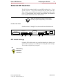
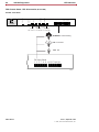
External DIP Switches
The ICX-250 is equipped with five external DIP switches (four - 12 dip
switches, and one - 7 dip switch) located on the rear panel of the unit.
These switches are used for Data Port and T1 Configuration. Each switch
is set to a preconfigured factory setting when shipped. The illustration
below outlines the location of these DIP switches.
Note: The individual switches on each switch
assembly operate independently of one another.
ICX-250 - Rear Panel
Switch numbers S1 through S5 are shown on the board within the unit.
Data 1
FXS Loop Pairs
1
FXS Loopback
12 13
24 Alm.
Data 1
Data 2
T1
Data 2
T1
T1 Line Rx 24/48 VDC
+–G
Tx
120 VAC–.6A 60Hz
11265-A
S5
S4
S3
S2
S1
DIP Switch Settings
Locate the DIP switch on the rear panel that describes the function you
wish to effect. Use the tip of a small object to change the switch settings.
The switches will glide easily into place.
TIP
Switch setting
changes will
take effect
immediately.
Issue 1, September 1998
© 1998, ADC Telecommunications, Inc.
ADCP-62-023
32
Configuring the ICX-250
External DIP Switches
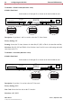
T1 Interface - Frame Format (DIP switch - back)
ICX-250 - Rear Panel
Switch numbers S1 through S5 are shown on the board within the unit.
Data 1
FXS Loop Pairs
FXS Loopback
12 13
1
24 Alm.
Data 1
T1
Data 2
Data 2
T1
T1 Line Rx 24/48 VDC
+–G
Tx
120 VAC–.6A 60Hz
S5
S4
S3
T1
ON
S2
11266-A
S1
T1
ON
DIP
T1
DIP
ON
DIP
1 2 3 4 5 6 7
1 2 3 4 5 6 7
1 2 3 4 5 6 7
D4 (SF)
ESF
TR-08
Description: S1 positions 1 and 2 are used to select the T1 frame format.
Factory Setting: ESF
Framing: Selects the T1 frame format to be either D4 (SF), ESF, or TR-08. (No data link with D4)
Selections: D4 (SF), ESF and TR-08. (Note: Position 1 and 2 to ON is not a valid setting and could
cause slips on the T1.)
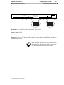
T1 Interface - Line Code (DIP switch - back)
ICX-250 - Rear Panel
Switch numbers S1 through S5 are shown on the board within the unit.
Data 1
FXS Loop Pairs
FXS Loopback
12 13
1
24 Alm.
Data 1
T1
Data 2
Data 2
T1
T1 Line Rx 24/48 VDC
+–G
Tx
120 VAC–.6A 60Hz
S5
S4
S3
S2
11267-A
S1
T1
ON
T1
DIP
ON
DIP
1 2 3 4 5 6 7
1 2 3 4 5 6 7
AMI
B8ZS
Description: S1 position 3 is used to select the T1 line code.
Factory Setting: B8ZS
Line Code: Selects the line code on the T1 interface.
Selections: AMI, B8ZS.
ADCP-62-023
© 1998, ADC Telecommunications, Inc.
Issue 1, September 1998
External DIP Switches
Configuring the ICX-250
33
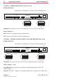
T1 Interface - T1 Clock (DIP switch - back)
ICX-250 - Rear Panel
Switch numbers S1 through S5 are shown on the board within the unit.
Data 1
FXS Loop Pairs
1
FXS Loopback
12 13
24 Alm.
Data 1
T1
Data 2
Data 2
T1
T1 Line Rx 24/48 VDC
+–G
Tx
120 VAC–.6A 60Hz
S5
S4
S3
S2
11268-A
S1
T1
ON
T1
DIP
ON
DIP
1 2 3 4 5 6 7
1 2 3 4 5 6 7
LINE
INTERNAL
Description: S1 position 4 is used to select the T1 clock source.
Factory Setting: LINE
Line: Clock for the T1 interface will be recovered from the line (receive signal).
Internal: Clock for the T1 interface will be taken from an on-board 1.544 MHz clock meeting the
Stratum 4 requirements.
Note: Failure of external clock causes unit to switch
to internal clock. When external clock is restored, the
unit will switch back to external clock source.
Issue 1, September 1998
© 1998, ADC Telecommunications, Inc.
ADCP-62-023
34
Configuring the ICX-250
External DIP Switches
T1 Interface - CSU/DSX Interface Selection (Dip switch - back)
ICX-250 - Rear Panel
Switch numbers S1 through S5 are shown on the board within the unit.
Data 1
FXS Loop Pairs
1
FXS Loopback
12 13
24 Alm.
Data 1
T1
Data 2
Data 2
T1
T1 Line Rx 24/48 VDC
+–G
Tx
120 VAC–.6A 60Hz
S5
S4
S3
S2
11269-A
S1
T1
ON
T1
DIP
ON
DIP
1 2 3 4 5 6 7
1 2 3 4 5 6 7
ACCEPT
IGNORE
Description: S1 position 5 is used to select whether the T1 acts as a CSU or DSX interface.
Factory Setting: CSU
DSX: SlimLine will exhibit DSX interface characteristics.
CSU: SlimLine will exhibit CSU interface characteristics.
T1 Interface - CSU/DSX Line Build Out (CSU) or Line Length (DSX) (DIP switch - back)
ICX-250 - Rear Panel
Switch numbers S1 through S5 are shown on the board within the unit.
Data 1
FXS Loop Pairs
1
FXS Loopback
12 13
24 Alm.
Data 1
Data 2
T1
Data 2
T1
T1 Line Rx 24/48 VDC
+–G
Tx
120 VAC–.6A 60Hz
S5
S4
S3
T1
ON
S2
11270-A
S1
T1
DIP
ON
T1
DIP
ON
DIP
1 2 3 4 5 6 7
1 2 3 4 5 6 7
1 2 3 4 5 6 7
0 dB
–7.5 dB
–15.0 dB
Description: S1 position 6 and 7 are used to select CSU/DSX line build out or line length.
Factory Setting: CSU 0dB
Line Build Out: Selects one of three line build out and line length options for either CSU
or DSX interfaces.
Selections: CSU 0 dB, –7.5 dB and –15.0 dB; DSX 0.6 dB at 250 ft, 1.8 dB at 500 ft, 3.0 dB at 700 ft.
ADCP-62-023
© 1998, ADC Telecommunications, Inc.
Issue 1, September 1998
External DIP Switches
Configuring the ICX-250
35
Data Port 1 and 2 - Number of Timeslots (DIP switch - back)
IICX-250 - Rear Panel
Switch numbers S1 through S5 are shown on the board within the unit.
Data 1
FXS Loop Pairs
1
FXS Loopback
12 13
24 Alm.
Data 1
Data 2
T1
Data 2
T1
T1 Line Rx 24/48 VDC
+–G
Tx
120 VAC–.6A 60Hz
S5
S4
S3
S2
S1
11271-A
Data 1 / Data 2
1 ON
0
DIP
1 2 3 4 5 6 7 8 9 10 11 12
Description: S2 positions 1, 2, 3, 4 and 5 (Data 2 - DIP switch) sets the port parameters for Data
Port 2. S3 positions 1, 2, 3, 4 and 5 (Data 1 -DIP switch) sets the port parameters for Data Port 1.
Both DIP switches are used for Network Data Bandwidth.
Factory Setting: All switches are set to zero (data ports inactive).
Number of Timeslots: Selects the number of consecutive timeslots that data from Data Port 1 and/
or 2 will be mapped onto. Please refer to Decimal/Binary Conversion Table (see page 36) for Data
Port Configuration to aid in selecting N. Drawing above indicates switch settings if timeslot N = 13.
Selected quantity of timeslots x 64K = Data Port Bandwidth.
Note: Binary numbers are used to select the number
of timeslots and starting timeslots.
Issue 1, September 1998
© 1998, ADC Telecommunications, Inc.
ADCP-62-023
36
Configuring the ICX-250
External DIP Switches
Decimal / Binary Conversion Table for Data Port Configuration
The table shown below illustrates the binary equivalent of Timeslots 1-24.
Note: 1 = ON and 0 = OFF.
Bandwidth
Timeslot
Switch Setting
Bandwidth
Timeslot
Switch Setting
--
0
00000
832K
13
01101
64K
1
00001
896K
14
01110
128K
2
00010
960K
15
01111
192K
3
00011
1024K
16
10000
256K
4
00100
1088K
17
10001
320K
5
00101
1152K
18
10010
384K
6
00110
1216K
19
10011
448K
7
00111
1280K
20
10100
512K
8
01000
1344K
21
10101
576K
9
01001
1408K
22
10110
640K
10
01010
1472K
23
10111
704K
11
01011
1536K
24
11000
768K
12
01100
Starting T/S
6
7
8
9
1
off
off
off
off
3
off
off
off
on
5
off
off
on
off
7
off
off
on
on
9
off
on
off
off
11
off
on
off
on
13
off
on
on
off
15
off
on
on
on
19
on
off
off
on
21
on
off
on
off
23
on
off
on
on
This table is used for selecting the starting timeslots for each data port.
ADCP-62-023
© 1998, ADC Telecommunications, Inc.
Issue 1, September 1998
External DIP Switches
Configuring the ICX-250
37
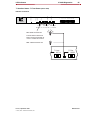
Data Port 1 and 2 - Starting Timeslot (DIP switch - back)
ICX-250 - Rear Panel
Switch numbers S1 through S5 are shown on the board within the unit.
Data 1
FXS Loop Pairs
1
FXS Loopback
12 13
24 Alm.
Data 1
Data 2
T1
Data 2
T1
T1 Line Rx 24/48 VDC
+–G
Tx
120 VAC–.6A 60Hz
S5
S4
S3
S2
S1
11272-A
Data 1 / Data 2
1 ON
0
DIP
1 2 3 4 5 6 7 8 9 10 11 12
Note: Starting time slots will always be odd
numbered (i.e. 1, 3, 5, 7, 9, etc.).
Description: S2 position 6, 7, 8 and 9 selects the starting timeslot (1,3,5,7,9,etc.) for Data Port 2.
S3 position 6, 7, 8 and 9 selects the starting timeslot (1,3,5,7,9,etc.) for data port 1.
Factory Setting: All switches are set to zero (data ports not active).
Starting Timeslot: Selects first T1 timeslot that data from Data Port 1 and/or 2 will be mapped.
(1,3,5,7,9....23). Please refer to Decimal/Binary Conversion Table (see page 36) to aid in selecting
the starting timeslot. Drawing above indicates switch settings using timeslot 6 as the starting timeslot.
Factory Setting: All switches are set to zero (data
ports not active).
Issue 1, September 1998
© 1998, ADC Telecommunications, Inc.
ADCP-62-023
38
Configuring the ICX-250
External DIP Switches
Data Port 1 and 2 - Clock Inversion - (DIP switch - back)
ICX-250 - Rear Panel
Switch numbers S1 through S5 are shown on the board within the unit.
Data 1
FXS Loop Pairs
FXS Loopback
12 13
1
24 Alm.
Data 1
T1
Data 2
Data 2
T1
T1 Line Rx 24/48 VDC
+–G
Tx
120 VAC–.6A 60Hz
S5
S4
S3
S2
11645-A
S1
Data 1 / Data 2
1 ON
0
DIP
1 2 3 4 5 6 7 8 9 10 11 12
Description: DTE clocking will usually require an off setting (S2 & S3 position 10 off).
If synchronization problems occur, clock inversion should be selected (S2 & S3 position 10 on).
Factory Setting: Clock set to OFF
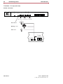
Data Port 1 and 2 - Data Interface Type - (DIP switch - back)
ICX-250 - Rear Panel
Switch numbers S1 through S5 are shown on the board within the unit.
Data 1
FXS Loop Pairs
FXS Loopback
12 13
1
24 Alm.
Data 1
T1
Data 2
Data 2
T1
T1 Line Rx 24/48 VDC
+–G
Tx
120 VAC–.6A 60Hz
S5
S4
S3
S2
Data 1
1 ON
0
11273-A
S1
Data 2
DIP
1 2 3 4 5 6 7 8 9 10 11 12
V.35
1 ON
0
DIP
1 2 3 4 5 6 7 8 9 10 11 12
EIA530A
Description: S2 and S3 position 11 selects the data interface for Data Ports 2 and 1.
Factory Setting: V.35
EIA530A: Data Ports 1 or 2 use the EIA530A standard.
V.35: Data Ports 1 or 2 use the V.35 standard.
ADCP-62-023
© 1998, ADC Telecommunications, Inc.
Issue 1, September 1998
External DIP Switches
Configuring the ICX-250
39
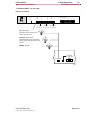
Data Port 1 and 2 Data Rate - (DIP switch - back)
ICX-250 - Rear Panel
Switch numbers S1 through S5 are shown on the board within the unit.
Data 1
FXS Loop Pairs
FXS Loopback
12 13
1
24 Alm.
Data 1
T1
Data 2
Data 2
T1
T1 Line Rx 24/48 VDC
+–G
Tx
120 VAC–.6A 60Hz
S5
S4
S3
S2
Data 1
Data 2
1 ON
0
11274-A
S1
1 ON
DIP
1 2 3 4 5 6 7 8 9 10 11 12
0
DIP
1 2 3 4 5 6 7 8 9 10 11 12
64 Kbps
56 Kbps
Description: S2 and S3 position 12 selects the data rate for Data Ports 2 and 1, respectively.
Factory Setting: 56Kbps
64 Kbps: Data Ports1 or 2 receive and transmit data at a multiple of 64 Kbps.
56 Kbps: Data Ports 1 or 2 receive and transmit data at a multiple of 56 Kbps.
The options shown on this page do not have to be matched. i.e. Port 1 can have a different interface
and speed than Port 2.
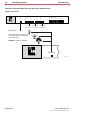
FXS Ports (per line) - Loopback Operation and/or Channel Unassigned (DIP switch - back)
ICX-250 - Rear Panel
Switch numbers S1 through S5 are shown on the board within the unit.
Data 1
FXS Loop Pairs
1
FXS Loopback
12 13
24 Alm.
Data 1
T1
Data 2
Data 2
T1
T1 Line Rx 24/48 VDC
+–G
Tx
120 VAC–.6A 60Hz
S5
S4
S3
FXS Loopback
1 ON
0
S2
S1
11275-A
FXS Loopback
DIP
1 2 3 4 5 6 7 8 9 10 11 12
1 ON
0
DIP
1 2 3 4 5 6 7 8 9 10 11 12
Description: Used to set loopback for each FXS channel.
Factory Setting: OFF
ON: Breaks the connections to and from the FXS Ports and loops the receive data back onto the
transmit path towards the T1. In the case of unassigned channels, provides an idle termination.
Issue 1, September 1998
© 1998, ADC Telecommunications, Inc.
ADCP-62-023
40
Configuring the ICX-250
External DIP Switches
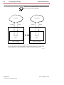
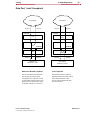
Note: It is recommended that all unassigned channels
be provided an idle termination.
T1 Network
Transmit
Receive
ICX-250
T24 Network
Transmit
Receive
ICX-250
FXS 1
FXS 24
FXS 1 Loopback
FXS 24 Loopback
The selected DS0 is looped after leaving the framer before reaching the FXS Interface.
The CPU is used to control this loopback via the Time Slot Assigner (TSA, a part of the
CPU). Subsystems T1 Line Interface Unit, T1 Framer, and CPU are exercised.
11276-A
ADCP-62-023
© 1998, ADC Telecommunications, Inc.
Issue 1, September 1998
Issue 1, September 1998
© 1998, ADC Telecommunications, Inc.
0
1
2
3
4
5
6
7
8
9
10
11
12
00000
00001
00010
00011
00100
00101
00110
00111
01000
01001
01010
01011
01100
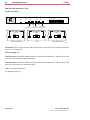
FXS Transmission Level
(Ports 13-24)
Ports 16 15 14 13
1 2 3 4 5 6 7 8
Ports 16 15 14 13
Ports 20 19 18 17
1 2 3 4 5 6 7 8
Ports 20 19 18 17
Ports 24 23 22 21
1 2 3 4 5 6 7 8
Ports 24 23 22 21
13
14
15
16
17
18
19
20
21
22
23
24
01101
01110
01111
10000
10001
10010
10011
10100
10101
10110
10111
11000
7
6
5
3
7
2
1
6
5
3
2
1
1 2 3 4 5 6 7 8
1 2 3 4 5 6 7 8
FXS Transmission Level
(Ports 1-12)
Ports 4
1 2 3 4 5 6 7 8
Ports 4
Ports 8
1 2 3 4 5 6 7 8
Ports 8
Ports 12 11 10 9
1 2 3 4 5 6 7 8
Ports 12 11 10 9
View From Top Rear
1
3
5
7
9
11
13
15
17
19
21
23
0000
0001
0010
0011
0100
0101
0110
0111
1000
1001
1010
1011
{
FXS Supervision
11658-A
Configuration Reference Data
Configuring the ICX-250
41
Configuration Reference Data
ADCP-62-023
Electrical Installation
CHAPTER
43
4
Electrical
Installation
When you are ready to go beyond the basics of the ICX-250
unit, use this chapter to learn specifics on grounding, cabling,
and the necessary power requirements for operation.
Contents
Connector Type . . . . . . . . . . . . . . . . . . . 44
Power Requirements . . . . . . . . . . . . . . . 47
Issue 1, September 1998
© 1998, ADC Telecommunications, Inc.
ADCP-62-023
44
Electrical Installation
Connector Type
Connector Type
The ICX-250 product is equipped with several types of electrical
connections to the network and power sources. The table below lists each
one of the connectors along with their functionality.
ICX-250 - Rear Panel
Switch numbers S1 through S5 are shown on the board within the unit.
Data 1
FXS Loop Pairs
1
FXS Loopback
12 13
24 Alm.
Data 1
Data 2
T1
Data 2
T1
T1 Line Rx 24/48 VDC
+–G
Tx
120 VAC–.6A 60Hz
11264-A
Connector Name
Connector Type
Description
FXS Loop Pairs
25 Pair Amphenol
24 FXS Tip and Ring pair
Signals: TIPn, RINGn
switch for FXS.
Alm.
2 position
(plug included with Kit of Parts)
A relay closure that sends alarms out to an external alarm system.
Data 1 and Data 2
DB25 Female
Data Port 1 signals and Data Port 2 signals.
T1 Line
RJ48
Transmit and Receive pairs.
T1
Dual Bantam Jack (monitor jacks)
For bridged access onto the T1 transmit and receive pairs.
24/48VDC (+– G)
1.8 / .9A Max.
3 position
(plug included with Kit of Parts)
For DC power input.
Note: FXSGND must be connected to earth ground regardless of
powering method used.
120 VAC -.6A 60Hz
AC Receptacle
Power input when external 120 VAC 60Hz is used to power the unit.
Earth Ground
Permanent Earth Ground Connection.
ADCP-62-023
Issue 1, September 1998
© 1998, ADC Telecommunications, Inc.
Connector Type
Electrical Installation
45
Connector Pinouts
DCE DB25 Female Connector (Data Ports 1 and 2)
Pin
Signal
Name
Mnemonic
Source
BA (A)
DTE
V.35
EIA-530A
1
Shield
2
Transmit Data
TXD+
X
3
Receive Data
RXD+
BB (A)
DCE
X
X
4
Request to Send
RTS+
CA (A)
DTE
X
X
5
Clear to Send
CTS+
CB (A)
DCE
X
X
6
DCE Ready
DSR+
CC
DCE
X
X
7
Signal Common
X
X
8
Receive Line Signal Detector
9
Receive Signal Element Timing
AB
X
X
DCD+
CF (A)
DCE
X
X
RXCLK-
DD (B)
DCE
X
X
10
Receive Line Signal Detector
DCD-
CF (B)
DCE
X
11
Transmit Signal Element Timing (DTE)
TXCLK
DA (B)
DTE
X
12
Transmit Signal Element Timing (DCE)
TXCLK-
DB (B)
DCE
X
X
13
Clear to Send
CTS-
CB (B)
DCE
14
Transmit Data
TXD-
BA (B)
DTE
X
X
X
15
Transmit Signal Element Timing (DCE)
TXCLK+
DB (A)
DCE
X
X
16
Receive Data
RXD-
BB (B)
DCE
X
X
X
17
Receive Signal Element Timing (DCE)
RXCLK+
DD (A)
DCE
18
Local Loopback
LL
LL
DTE
X
19
Request to Send
RTS-
CA (B)
DTE
X
20
DTE Ready
DTR+
CD
DTE
X
21
Remote Loopback
RL
RL
DTE
X
DCE
22
Ring Indicator
CE
23
Signal Common
AC
24
Transmit Signal Element Timing (DTE)
25
Test Mode
TXCLK
DA (A)
TM
TM
X
X
X
DCE
X
Note: For purposes of connection and function,
the ICX-250 should be considered a DCE.
Issue 1, September 1998
© 1998, ADC Telecommunications, Inc.
ADCP-62-023
46
Electrical Installation
Connector Type
25 Pair Female Amphenol Connector
Port
Designation
Pin
Port
Designation
Pin
1
1
2
2
3
3
4
4
5
5
6
6
7
7
8
8
9
9
10
10
11
11
12
12
T
R
T
R
T
R
T
R
T
R
T
R
T
R
T
R
T
R
T
R
T
R
T
R
26
1
27
2
28
3
29
4
30
5
31
6
32
7
33
8
34
9
35
10
36
11
37
12
13
13
14
14
15
15
16
16
17
17
18
18
19
19
20
20
21
21
22
22
23
23
24
24
T
R
T
R
T
R
T
R
T
R
T
R
T
R
T
R
T
R
T
R
T
R
T
R
Not Assigned
Not Assigned
38
13
39
14
40
15
41
16
42
17
43
18
44
19
45
20
46
21
47
22
48
23
49
24
50
25
RJ48 Connector
ADCP-62-023
RJ-48(F) Pin
Signal
1
R1
2
T1
4
R
5
T
3,6,7,8
Not Assigned
Issue 1, September 1998
© 1998, ADC Telecommunications, Inc.
Power Requirements
Electrical Installation
47
Power Requirements
The installation site should have a 120VAC power receptacle readily
available to power up the unit. The unit can also be powered by –48VDC
or +/–24VDC.
Power Installation
A.C. Power Installation
The ICX-250 unit is equipped with an AC receptacle located on the back
of the unit.
D.C. Power Installation
When wiring to an external power source, such as a battery rack, fuse
panel, or circuit breaker, make sure that the correct rating of wire is used.
It is recommended you use 20 to 18 gauge wire.
Note: The ICX-250 unit can have both an AC and DC
power source connected to it at the same time. These
two power inputs will share the power load. However,
if one fails the other will carry the full load.
DC Power Plug (supplied)
wire tightening screws
(located on top of adapter)
+ -
Wire
(not supplied)
Issue 1, September 1998
© 1998, ADC Telecommunications, Inc.
G
Small Screwdriver
(not supplied)
ADCP-62-023
48
Electrical Installation
Power Requirements
Alarm
The ICX-250 unit is equipped with an external alarm connector (located
on the rear panel of the unit) that will close in the event of an alarm
condition such as: T1 failure, internal failure, or power failure. A Red
alarm is detected by the T1 interface and responded to by issuing the
yellow alarm signal on the T1. The figure below illustrates the alarm
connector. It is recommended you use 26 to 24 gauge twisted-pair wire.
Alarm Closure Plug (supplied)
Wire
(not supplied)
Small Screwdriver
(not supplied)
wire tightening screws
(located under adapter)
Grounding Requirements
Due to the UL regulatory requirements, a mounting stud is required for
connection of the AC input earth ground lead to the ICX-250 chassis.
The ground lead must be connected to the chassis using a No. 6 nut and
lock washer combination. The mounting location is labeled with the IEC
417 No. 5019 symbol ( ) to identify this as the AC earth ground
connection point. This mounting stud is located next to the IEC 320 AC
input connector.
The loop battery return and the FXS digital and analog circuitry must
share a common ground. The access point on the back panel of the ICX250 product allows connection to an external battery return lead which
will be physically connected to the FXS circuit ground. This access point
is provided as part of the DC power input connector.
Grounding
Symbol
attached to external ground
location
ADCP-62-023
No. 6 nut
and lock washer
120 VAC - .6A 60Hz
Issue 1, September 1998
© 1998, ADC Telecommunications, Inc.
Power Requirements
Electrical Installation
49
Cabling
The following cables are recommended for use with the ICX-250 unit.
Cable
Used for
Description
Voice
FXS Ports
50-pin Amphenol (M) to 50 pin Amphenol
(M) (5’)
Data
Data Ports
EIA530A
DB25M to DB25F (Straight through) (5’)
Data
Data Ports
V.35
DB25M to M34F (Straight through) (5’)
T1
RJ48 Port
RJ48M to RJ48M Shielded (1’)
T1
RJ48 Port
RJ48M to RJ48M Shielded (25’)
AC Power
AC Power Input
AC Power Cable (6’)
Issue 1, September 1998
© 1998, ADC Telecommunications, Inc.
ADCP-62-023
ICX-250 Diagnostics
CHAPTER
51
5
ICX-250
Diagnostics
This chapter describes how to run test patterns and to diagnose
events taking place within the ICX-250 unit.
Contents
Testing . . . . . . . . . . . . . . . . . . . . . . . . . . 52
LED Indicators . . . . . . . . . . . . . . . . . . . . 61
Issue 1, September 1998
© 1998, ADC Telecommunications, Inc.
ADCP-62-023
52
ICX-250 Diagnostics
Testing
Testing
Slide Switch Settings
The ICX-250 is equipped with five external slide switches (four - 3
position, one - 2 position) located on the front panel of the unit. They are
used for T1 and Data Port test and Loopback Transmit / Receive paths.
Each switch is factory set to the off position. The switches should be
checked to be sure positioning hasn’t changed during shipment. The
illustration below outlines the location of the slide switches.
Locate the slide switch on the front panel that implements the function
desired. Use the end of a small object or the tip of your finger to change
the switch settings.
Test Pattern
Test Pattern
T1 Loop
T1 Status
T1 Test
Self Check
ICX-250 - Front Panel
ICX-250
FXS Status Channel
1 3 5 7 9 11 13 15 17 19 21 23
2 4 6 8 10 12 14 16 18 20 22 24
Off / QRSS
1 / Off / 2
11261-A
T1 Loop
Data Loop 1 Data Loop 2
Net. / Off / Lcl. Lcl. / Off / Net. Lcl. / Off / Net.
TIP
Switch setting
changes will
take effect
immediately.
ADCP-62-023
Issue 1, September 1998
© 1998, ADC Telecommunications, Inc.
Testing
ICX-250 Diagnostics
53
The bold highlighted selected under “Options” is the Factory Setting.
Function
Switch
Switch
Location
Options
Description
T1 INTERFACE:
T1 Interface
T1 Loopback
(see page 54)
T1 Loopback
Front (slide)
Network
Local
Off
Network: Loops signal back to the network and breaks the transmit and receive
paths between the Framer and LIU and
loops T1 receive onto the T1 transmit
within the Framer chip.
Local: Loops signal back to the network
and breaks the transmit and receive paths
between the LIU and the line and loops
the T1 transmit signal onto the T1 receive
within the LIU.
T1 Test
Pattern
QRSS
(see page 56)
QRSS
Quasi Random Signal
Source. Used for
diagnostic capabilities
for analog, remote and
dual loopbacks as well
as remote test.
Front (slide)
On
Off
On: All connections between either Data
Ports or the FXS Ports and the T1 interface are broken and a QRSS pattern is
transmitted onto the T1 interface. At this
time the T1 Test Pattern LED will light
when QRSS is being transmitted.
Note: ONLY works with framed T1.
DATA PORTS:
Loopback
(see page 58)
Data Port 1 and 2
Loopback
Front (slide)
Local
Network
Off
Local: Breaks the receive signal on the
network side between the Data Port 1 or 2
and the T1 interface and loops the Data
Port 1 or 2 transmit signal onto the
receive side.
Network: Breaks the transmit signal on
the network side between the Data Port 1
or 2 and the T1 interface and loops the
Data Port 1 or 2 receive signal onto the
transmit side.
Test Pattern
(see page 60)
1 / Off / 2
Front (slide)
1: Test Port 1
2: Test Port 2
OFF: no Test
1: Breaks the transmit and receive paths
between the Data Port 1 line and the
receiver and inserts the 2047 pattern onto
the transmit path. Also turns on the 2047
receiver.
2: Breaks the transmit and receive paths
between the Data Port 2 line and the
receiver and inserts the 2047 pattern onto
the transmit path. Also turns on the 2047
receiver.
OFF: 2047 function is disabled.
Issue 1, September 1998
© 1998, ADC Telecommunications, Inc.
ADCP-62-023
54
ICX-250 Diagnostics
Testing
T1 Interface - T1 Loopback (Slide switch - front)
Test Pattern
Test Pattern
T1 Loop
T1 Status
T1 Test
Self Check
ICX-250 - Front Panel
ICX-250
FXS Status Channel
1 3 5 7 9 11 13 15 17 19 21 23
2 4 6 8 10 12 14 16 18 20 22 24
Off / QRSS
1 / Off / 2
T1 Loop
Data Loop 1 Data Loop 2
Net. / Off / Lcl. Lcl. / Off / Net. Lcl. / Off / Net.
T1 Loop
Net. Off Lcl.
NETWORK
T1 Loop
Net. Off Lcl.
LOCAL
T1 Loop
Net. Off Lcl.
OFF
11279-A
Description: This is a three position slide switch used to operate the T1 Interface Loopback.
Factory Setting: OFF
Network: Loops signal back to the network and breaks the transmit and receive paths between the
Framer and LIU and Loops the T1 receive onto the T1 transmit within the Framer chip.
Local: Loops signal back to the network and breaks the transmit and receive paths between the
LIU and the line and loops the T1 transmit signal onto the T1 receive within the LIU.
Note: When operating the QRSS switch the
T1 Loopback switch will be inoperative.
ADCP-62-023
Issue 1, September 1998
© 1998, ADC Telecommunications, Inc.
Testing
ICX-250 Diagnostics
55
T1 Loopback
T1 Network
Receive
T1 Network
Transmit
ICX-250
Receive
Transmit
ICX-250
LIU
LIU
FRAMER
FRAMER
CPU
Receive
CPU
Transmit
Receive
Transmit
CPE Device
CPE Device
Network or Remote Loopback
Local Loopback
The incoming T1 signal is looped
inside the T1 Framer and returned to
the T1 Network. This exercises the
T1 Line Interface Unit and the T1
Framer with the exception of the
HDLC controller and clock switching
circuitry.
The outgoing T1 signal is looped
inside the T1 LIU and returned to the
CPE Device. This exercises the T1
Line Interface Unit, the T1 Framer,
CPU, Data Port Interface, and the
FXS Interface with the exception of
the HDLC controller. The data ports
can be exercised up to full T1 rate.
11277-A
Issue 1, September 1998
© 1998, ADC Telecommunications, Inc.
ADCP-62-023
56
ICX-250 Diagnostics
Testing
T1 Interface - T1 Test Pattern QRSS (Slide switch - front)
Test Pattern
Test Pattern
T1 Loop
T1 Status
T1 Test
Self Check
ICX-250 - Front Panel
FXS Status Channel
1 3 5 7 9 11 13 15 17 19 21 23
ICX-250
2 4 6 8 10 12 14 16 18 20 22 24
Off / QRSS
1 / Off / 2
T1 Loop
Data Loop 1 Data Loop 2
Net. / Off / Lcl. Lcl. / Off / Net. Lcl. / Off / Net.
T1 Test
Off QRSS
T1 Test
Off QRSS
11280-A
QRSS
Off
Description: This is a two position slide switch used for T1 Interface testing.
Factory Setting: OFF
On: All connections between either the Data Ports or the FXS Ports and the T1 interface are
broken and a QRSS pattern is transmitted onto the T1 interface. At this time the T1 Test pattern
LED will light when QRSS is being transmitted. (see section on LED).
Note: The T1 test pattern for QRSS only works
with framed T1.
Note: The T1 test LED will come on when the
QRSS switch is turned ON. When operating the
QRSS switch the T1 Loopback switch will be
inoperative.
ADCP-62-023
Issue 1, September 1998
© 1998, ADC Telecommunications, Inc.
Testing
ICX-250 Diagnostics
57
ICX-250
T1 Interface
QRSS
Transmitter
Internal Control and Routing
2047
Pattern
Detector
2047
Transmitter
Data Port 1
Issue 1, September 1998
© 1998, ADC Telecommunications, Inc.
2047
Pattern
Detector
2047
Transmitter
Data Port 2
ADCP-62-023
58
ICX-250 Diagnostics
Testing
Data Port 1 and 2 - Loopback (Slide switches - front)
Test Pattern
Test Pattern
T1 Loop
T1 Status
T1 Test
Self Check
ICX-250 - Front Panel
ICX-250
FXS Status Channel
1 3 5 7 9 11 13 15 17 19 21 23
2 4 6 8 10 12 14 16 18 20 22 24
Off / QRSS
1 / Off / 2
T1 Loop
Data Loop 1 Data Loop 2
Net. / Off / Lcl. Lcl. / Off / Net. Lcl. / Off / Net.
Data Loop 1
Lcl. Off Net
LOCAL
Data Loop 2
Lcl. Off Net
LOCAL
Data Loop 1
Lcl. Off Net
OFF
Data Loop 2
Lcl. Off Net
OFF
Data Loop 1
Lcl. Off Net
NETWORK
Data Loop 2
Lcl. Off Net
NETWORK
11281-A
Description: This is a three position slide switch used for Data Port 1 and 2 to receive and transmit
T1 loopback information.
Factory Setting: OFF
Local: Breaks the receive signal on the network side between the Data Port (1 or 2) and the T1
interface and loops the Data Port (1 or 2) transmit signal onto the receive side.
Network: Breaks the transmit signal on the network side between the Data Port (1 or 2) and the T1
interface and loops the Data Port (1 or 2) receive signal onto the transmit side.
ADCP-62-023
Issue 1, September 1998
© 1998, ADC Telecommunications, Inc.
Testing
ICX-250 Diagnostics
59
Data Port 1 and 2 Loopback
T1 Network
Receive
T1 Network
Transmit
ICX-250
Receive
Transmit
ICX-250
LIU
LIU
FRAMER
FRAMER
CPU
Receive
CPU
Transmit
CPE Device
Data Port 1 and 2
Receive
Transmit
CPE Device
Data Port 1 and 2
11278-A
Network or Remote Loopback
Local Loopback
The selected DS0s are looped back
after leaving the Framer before
reaching the CPU. The CPU is used
to control this loopback via the TSA.
Subsystems T1 Line Interface Unit,
T1 Framer, and CPU are exercised.
The Data Port interface signal is
looped inside the CPU and returned
to the data port interface. Subsystems CPU and Data Port interface are exercised.
Issue 1, September 1998
© 1998, ADC Telecommunications, Inc.
ADCP-62-023
60
ICX-250 Diagnostics
Testing
Data Port Test (Slide switch - front)
Test Pattern
Test Pattern
T1 Loop
T1 Status
T1 Test
Self Check
ICX-250 - Front Panel
ICX-250
FXS Status Channel
1 3 5 7 9 11 13 15 17 19 21 23
2 4 6 8 10 12 14 16 18 20 22 24
Off / QRSS
1 / Off / 2
T1 Loop
Data Loop 1 Data Loop 2
Net. / Off / Lcl. Lcl. / Off / Net. Lcl. / Off / Net.
Test Pattern
1 Off 2
TEST PATTERN 1
Test Pattern
1 Off 2
OFF
Test Pattern
1 Off 2
TEST PATTERN 2
11282-A
Description: This is a three position slide switch used to connect the Test Generator to the Data
Port (1 or 2) Transmit side.
Factory Setting: OFF
Test Data Port 1: Breaks the transmit and receive paths between Data Port 1 and the receiver and
injects the 2047 pattern onto the transmit path.
Test Data Port 2: Breaks the transmit and receive paths between Data Port 2 and the receiver and
injects the 2047 pattern onto the transmit path.
Off: 2047 function is disabled.
See diagram on page 55.
ADCP-62-023
Issue 1, September 1998
© 1998, ADC Telecommunications, Inc.
LED Indicators
ICX-250 Diagnostics
61
LED Indicators
The LED indicator lights are labeled and located on the front panel of the ICX-250. The table
shown below describes the LED location and function.
Test Pattern
Test Pattern
T1 Loop
T1 Status
T1 Test
Self Check
ICX-250 - Front Panel
FXS Status Channel
1 3 5 7 9 11 13 15 17 19 21 23
ICX-250
2 4 6 8 10 12 14 16 18 20 22 24
Off / QRSS
11261-A
1 / Off / 2
T1 Loop
Data Loop 1 Data Loop 2
Net. / Off / Lcl. Lcl. / Off / Net. Lcl. / Off / Net.
LED
Function
Display Status
Self Check
(Red LED)
Self Check
(see page 62)
ON: Power-Up Self Test Failed or System Failure occurred.
BLINKING: Invalid Configuration
T1 Status
(Tri-color LED)
T1 Interface
Status
(see page 63)
RED: Red Alarm
YELLOW: Yellow Alarm
GREEN: Normal
T1 Loop
(Yellow LED)
(see page 64)
ON: Network
BLINKING: Local
OFF: None
T1 Test Pattern
Sync (Green LED)
(see page 65)
GREEN: QRSS On
OFF: No QRSS
Test Pattern Sync
(Green LED)
Data Port 1
(see page 66)
GREEN: Sync
OFF: No Sync
Test Pattern Sync
(Green LED)
Data Port 2
(see page 67)
GREEN: Sync
OFF: No Sync
FXS N Connection
(Green LED)
FXS Channel
Status (x 24)
(see page 68)
BLINKING: Call Processing
ON: Busy
OFF: Idle
Issue 1, September 1998
© 1998, ADC Telecommunications, Inc.
ADCP-62-023
62
ICX-250 Diagnostics
LED Indicators
Self Check (Red LED) Failed Power-Up Self Test or System Failure
Test Pattern
Test Pattern
T1 Loop
T1 Status
T1 Test
Self Check
ICX-250 - Front Panel
ICX-250
FXS Status Channel
1 3 5 7 9 11 13 15 17 19 21 23
2 4 6 8 10 12 14 16 18 20 22 24
Off / QRSS
1 / Off / 2
T1 Loop
Data Loop 1 Data Loop 2
Net. / Off / Lcl. Lcl. / Off / Net. Lcl. / Off / Net.
OFF: Normal
ON: Failed Self Test during power up
or a system failure occured during
normal operation.
BLINKING: Invalid Configuration
Self Check
ICX-250
ADCP-62-023
11283-A
Issue 1, September 1998
© 1998, ADC Telecommunications, Inc.
LED Indicators
ICX-250 Diagnostics
63
T1 Interface Status - (tri-color LED)
Test Pattern
Test Pattern
T1 Loop
T1 Status
T1 Test
Self Check
ICX-250 - Front Panel
FXS Status Channel
1 3 5 7 9 11 13 15 17 19 21 23
ICX-250
2 4 6 8 10 12 14 16 18 20 22 24
Off / QRSS
1 / Off / 2
T1 Loop
Data Loop 1 Data Loop 2
Net. / Off / Lcl. Lcl. / Off / Net. Lcl. / Off / Net.
OFF: Red Alarm
Indicates a loss of signal on the
receive side of the T1.
YELLOW: Yellow Alarm
Indicates that the near end transmit
path is open but that the receive side
is intact.
GREEN: Normal
T1 Loop
Net. Off Lcl.
T1 Status
11284-A
Issue 1, September 1998
© 1998, ADC Telecommunications, Inc.
ADCP-62-023
64
ICX-250 Diagnostics
LED Indicators
T1 Interface - T1 Loop (Yellow LED)
Test Pattern
Test Pattern
T1 Loop
T1 Status
T1 Test
Self Check
ICX-250 - Front Panel
FXS Status Channel
1 3 5 7 9 11 13 15 17 19 21 23
ICX-250
2 4 6 8 10 12 14 16 18 20 22 24
Off / QRSS
1 / Off / 2
T1 Loop
Data Loop 1 Data Loop 2
Net. / Off / Lcl. Lcl. / Off / Net. Lcl. / Off / Net.
ON: Network
Blinking: Local
OFF: None
T1 Loop
Net. Off Lcl.
T1 Status
11285-A
ADCP-62-023
Issue 1, September 1998
© 1998, ADC Telecommunications, Inc.
LED Indicators
ICX-250 Diagnostics
65
T1 Interface Status - T1 Test Pattern (Green LED)
Test Pattern
Test Pattern
T1 Loop
T1 Status
T1 Test
Self Check
ICX-250 - Front Panel
FXS Status Channel
1 3 5 7 9 11 13 15 17 19 21 23
ICX-250
2 4 6 8 10 12 14 16 18 20 22 24
Off / QRSS
1 / Off / 2
T1 Loop
Data Loop 1 Data Loop 2
Net. / Off / Lcl. Lcl. / Off / Net. Lcl. / Off / Net.
ON: QRSS Test Mode ON
Indicates that the QRSS Test
Pattern is being transmitted out
on the T1 towards the network.
OFF: QRSS Test Mode OFF
T1 Loop
Net. Off Lcl.
T1 Test
Off QRSS
11286-A
Issue 1, September 1998
© 1998, ADC Telecommunications, Inc.
ADCP-62-023
66
ICX-250 Diagnostics
LED Indicators
Data Port 1 - Test Pattern Sync (Green LED)
Test Pattern
Test Pattern
T1 Loop
T1 Status
T1 Test
Self Check
ICX-250 - Front Panel
ICX-250
FXS Status Channel
1 3 5 7 9 11 13 15 17 19 21 23
2 4 6 8 10 12 14 16 18 20 22 24
Off / QRSS
1 / Off / 2
T1 Loop
Data Loop 1 Data Loop 2
Net. / Off / Lcl. Lcl. / Off / Net. Lcl. / Off / Net.
ON: Sync
A Green LED indicates that the
test pattern received by the
Data Port (1 or 2) pattern
detector matches the pattern
generated by the system.
OFF: No Sync
Test Pattern
1 Off 2
11287-A
ADCP-62-023
Issue 1, September 1998
© 1998, ADC Telecommunications, Inc.
LED Indicators
ICX-250 Diagnostics
67
Data Port 2 - Test Pattern Sync (Green LED)
Test Pattern
Test Pattern
T1 Loop
T1 Status
T1 Test
Self Check
ICX-250 - Front Panel
ICX-250
FXS Status Channel
1 3 5 7 9 11 13 15 17 19 21 23
2 4 6 8 10 12 14 16 18 20 22 24
Off / QRSS
1 / Off / 2
T1 Loop
Data Loop 1 Data Loop 2
Net. / Off / Lcl. Lcl. / Off / Net. Lcl. / Off / Net.
ON: Sync
A Green LED indicates that the
test pattern received by the
Data Port (1 or 2) pattern
detector matches the pattern
generated by the system.
OFF: No Sync
Test Pattern
1 Off 2
11288-A
Issue 1, September 1998
© 1998, ADC Telecommunications, Inc.
ADCP-62-023
68
ICX-250 Diagnostics
LED Indicators
FXS Channel Status - FXS N Connection (Green LED)
Test Pattern
Test Pattern
T1 Loop
T1 Status
T1 Test
Self Check
ICX-250 - Front Panel
ICX-250
FXS Status Channel
1 3 5 7 9 11 13 15 17 19 21 23
2 4 6 8 10 12 14 16 18 20 22 24
Off / QRSS
1 / Off / 2
T1 Loop
Data Loop 1 Data Loop 2
Net. / Off / Lcl. Lcl. / Off / Net. Lcl. / Off / Net.
BLINKING: Call Processing
ON: Connected
OFF: Idle
FXS Status Channel
1 3 5 7 9 11 13 15 17 19 21 23
2 4 6 8 10 12 14 16 18 20 22 24
11289-A
ADCP-62-023
Issue 1, September 1998
© 1998, ADC Telecommunications, Inc.
GENERAL INFORMATION
CHAPTER
69
6
GENERAL
INFORMATION
WARRANTY/SOFTWARE
The Product and Software warranty policy and warranty period for all
Products of ADC Telecommunications, Inc. (hereinafter referred to as
ADC) is published in ADC’s Warranty/Software Handbook. Contact the
Business Broadband Group (BBG) Technical Assistance Center at 1-800366-3891, extension 3223 (in U.S.A. or Canada) or 612-946-3223
(outside U.S.A. and Canada) for warranty or software information or for a
copy of the Warranty/Software Handbook.
REPAIR/ADVANCE REPLACEMENT POLICY
All repairs of ADC Products must be done by ADC or an authorized
representative. Any attempt to repair or modify ADC Products without
prior written authorization from ADC shall void ADC’s warranty.
If a malfunction cannot be resolved by the normal troubleshooting
procedures, call the BBG Technical Assistance Center at 1-800-366-3891,
extension 3223 (in U.S.A. or Canada) or 612-946-3223 (outside U.S.A.
and Canada). A telephone consultation can sometimes resolve a problem
without the need to repair or replace the ADC Product.
If, during a telephone consultation, ADC determines the ADC Product
requires repair, ADC will authorize the return of the affected Product by the
issue of a Return Material Authorization number and complete return
shipping instructions. If service is affected, ADC can arrange to ship a
replacement Product when available from designated inventory. In all cases,
the defective Product must be carefully packaged to eliminate damage, and
returned to ADC in accordance with issued ADC instructions.
REPAIR CHARGES
If the defect and the necessary repairs are covered by warranty, Buyer’s
only obligation is the payment of all transportation and associated costs in
returning the defective Product to the location designated by ADC. ADC,
at its option, will either repair or replace the Product at no charge and
return the Product to Buyer with transportation costs paid by ADC, only
Issue 1, September 1998
© 1998, ADC Telecommunications, Inc.
ADCP-62-023
70
GENERAL INFORMATION
when ADC contracted carriers are used. Requested return of Product by
any other means will be at Buyer’s cost. Buyer is responsible for all other
associated costs in return of Products from ADC. If Product is Out of
Warranty or NTF (no trouble found), ADC will charge a percentage of the
current Product list price. To obtain the percentage factor for Out of
Warranty or NTF Product, contact the ADC Product Return Department
at 1-800-366-3891, extension 3000 (in U.S.A. or Canada) or 612-9463000 (outside U.S.A. and Canada).
If a service effecting advance replacement Product is requested, the
current list price of a new Product will be charged initially. Customer
purchase order is required to ship an advance replacement Product. Upon
receipt of the defective Product, ADC will credit Buyer with twenty
percent (20%) of Product list price charged for any returned Product
found to be Out of Warranty, or one hundred percent (100%) credit for
any In Warranty Product under the Program terms. Products must be
returned within thirty (30) days to be eligible for any advance replacement
credit. If repairs necessitate a field visit by an ADC representative,
customer authorization (purchase order) must be obtained prior to
dispatching a representative, ADC will charge the current price of a field
visit plus round trip transportation charges from Minneapolis to the
customer’s site.
REPLACEMENT/SPARE PRODUCTS
Replacement parts, including but not limited to button caps and lenses,
lamps, fuses, and patch cords, are available from ADC on a special order
basis. Contact the BBG Technical Assistance Center at 1-800-366-3891,
extension 3223 (in U.S.A. or Canada) or 612-946-3223 (outside U.S.A.
and Canada) for additional information.
Spare Products and accessories can be purchased from ADC. Contact
Sales Administration at 1-800-366-3891, extension 3000 (in U.S.A. or
Canada) or 612-946-3000 (outside U.S.A. and Canada) for a price quote
and to place your order.
RETURNED MATERIAL
Contact the ADC Product Return Department at 1-800-366-3891,
extension 3000 (in U.S.A. or Canada) or 612-946-3000 (outside U.S.A.
and Canada) to obtain a Return Material Authorization number prior to
returning an ADC Product.
All returned Products must have a Return Material Authorization (RMA)
number clearly marked on the outside of the package. The Return
Material Authorization number is valid for thirty (30) days from
authorization.
ADCP-62-023
© 1998, ADC Telecommunications, Inc.
Issue 1, September 1998
GENERAL INFORMATION
71
SYSTEM INTEGRATION SERVICES
ADC offers the following system integration services. For calls originating
in the U.S.A. or Canada, dial 1-800-366-3891, extension 3000. For calls
originating outside the U.S.A. or Canada, dial 612-946-3000.
Technical Assistance Center
•
•
•
•
•
Product Management
Project Engineering
Project Administration
System Turn-Up and Test Support
Service/Maintenance Agreements
Technical Training
• Product Technology
• Custom Designed Training
Technical Operations
• Detail Engineering
• End-to-End Installation
• Drafting Services
CUSTOMER SUPPORT SERVICES
ADC offers the following customer support services. For calls originating
in the U.S.A. or Canada, dial 1-800-366-3891, then request the extension
listed. For calls originating outside the U.S.A. or Canada, dial 612-9463000 or 612-946-3223.
BBG Technical Assistance Center
Extension 3223
•
•
•
•
•
•
•
•
•
Technical Information
System/Network Configuration
Product Specification
Product Application
Proposals
Training
Installation and Operation Assistance
Troubleshooting and Repair
Field Assistance
Sales Administration
Extension 3000
•
•
•
•
Quotation
Ordering
Delivery
General Product Information
Product Return Department
Extension 3478
• ADC Return Authorization number and instructions
must be obtained before returning products.
Product information and service can also be obtained by writing ADC
Telecommunications, Inc., P.O. Box 1101, Minneapolis, Minnesota 554401101, U.S.A.
Issue 1, September 1998
© 1998, ADC Telecommunications, Inc.
ADCP-62-023
72
GENERAL INFORMATION
Contents herein are current as of the date of publication. ADC reserves the right to change the contents without prior
notice. In no event shall ADC be liable for any damages resulting from loss of data, loss of use, or loss of profits
and ADC further disclaims any and all liability for indirect, incidental, special, consequential or other similar
damages. This disclaimer of liability applies to all products, publications and services during and after the
warranty period.
This publication may be verified at any time by contacting ADC’s Technical Assistance Center at 1-800-366-3891, extension
3223 (in U.S.A. or Canada) or 612-946-3223 (outside U.S.A. and Canada), or by writing to ADC Telecommunications, Inc.,
Attn: Technical Assistance Center, Mail Station #77, P.O. Box 1101, Minneapolis, MN 55440-1101, U.S.A.
© 1998, ADC Telecommunications, Inc.
All Rights Reserved
Printed in U.S.A.
ADCP-62-023
© 1998, ADC Telecommunications, Inc.
Issue 1, September 1998