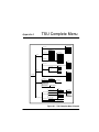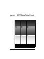
1
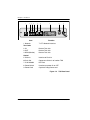
TSU
T1-FT1 Data/Channel Service Unit
Part Number 1200060L1
User Manual
61200060L1-1B
September 1999
901 Explorer Boulevard
P.O. Box 140000
Huntsville, AL 35814-4000
(256) 963-8000
© 1999 ADTRAN, Inc.
All Rights Reserved.
Printed in U.S.A.
Notes provide additional useful information.
Cautions signify information that could prevent service interruption.
Warnings provide information that could prevent damage to the
equipment or endangerment to human life.
iii
FCC regulations require that the following information be provided to the
customer in this manual.
1.
This equipment complies with Part 68 of the FCC rules. The required
label is affixed to the bottom of the chassis.
2. If your telephone equipment causes harm to the telephone network, the
Telephone Company may discontinue your service temporarily. If possible, they will notify you in advance. But if advance notice isn’t practical, you will be notified as soon as possible. You will be advised of your
right to file a complaint with the FCC.
3. Your telephone company may make changes in its facilities, equipment,
operations, or procedures that could affect the proper operation of your
equipment. If they do, you will be given advance notice so as to give
you an opportunity maintain uninterrupted service.
4. If you experience trouble with this equipment, please contact Adtran at
888-4Adtran for repair/warranty information. The telephone company
may ask you to disconnect this equipment from the network until the
problem has been corrected, or until you are sure the equipment is not
malfunctioning.
5. This unit contains no user-serviceable parts.
6. An FCC compliant telephone cord and modular plug is provided with
this equipment. This equipment is designed to be connected the telephone network or premises wiring using a compatible modular jack
which is Part 68 compliant. See installation instructions for details.
7. The following information may be required when applying to your
local telephone company for leased-line facilities.
iv
Service
REN/SOC FIC
USOC
1.544 Mbps - SF
6.0/F
04DU9-BN
RJ48C
1.544 Mbps - SF and B8ZS
6.0/F
04DU9-DN
RJ48C
1.544 Mbps - ESF
6.0/F
04DU9-1KN RJ48C
1.544 Mbps - ESF and B8ZS
6.0/F
04DU9-1SN RJ48C
Federal Communications Commission Radio
Frequency Interference Statement
This equipment has been tested and found to comply with the limits for a Class
A digital device, pursuant to Part 15 of the FCC Rules. These limits are designed
to provide reasonable protection against harmful interference when the equipment is operated in a commercial environment. This equipment generates, uses,
and can radiate radio frequency energy and, if not installed and used in accordance with the instruction manual, may cause harmful interference to radio frequencies. Operation of this equipment in a residential area is likely to cause
harmful interference, in which case the user will be required to correct the interference at his own expense.
Shielded cables must be used with this unit to ensure compliance
with Class A FCC limits.
Change or modifications to this unit not expressly approved by
the party responsible for compliance could void the user’s authority to operate the equipment.
v
Important Safety Instructions
When using your telephone equipment, please follow these basic safety precautions to reduce the risk of fire, electrical shock, or personal injury:
1.
Do not use this product near water, such as near a bath tub, wash bowl,
kitchen sink, laundry tub, in a wet basement, or near a swimming pool.
2. Avoid using a telephone (other than a cordless-type) during an electrical storm. There is a remote risk of shock from lightning.
3. Do not use the telephone to report a gas leak in the vicinity of the leak.
4. Use only the power cord, power supply, and/or batteries indicated in
the manual. Do not dispose of batteries in a fire. They may explode.
Check with local codes for special disposal instructions.
SAVE THESE INSTRUCTIONS
vi
WARRANTY AND CUSTOMER SERVICE
ADTRAN will replace or repair this product within five years from the date of
shipment if the product does not meet its published specifications or if it fails
while in service. For detailed warranty, repair, and return information see the
ADTRAN Equipment Warranty and Repair and Return Policy Procedure on the
inside back page of this manual.
Return Material Authorization (RMA) is required prior to returning equipment
to ADTRAN.
For service, RMA requests, or more information, contact one of the numbers
found on the inside back page of this manual.
vii
viii
Table of Contents
Chapter 1. Introduction .......................................................................................... 1-1
T1/FT1 Overview ..................................................................................................... 1-1
T1 Service Offerings........................................................................................... 1-1
Fractional T1........................................................................................................ 1-2
TSU Overview ........................................................................................................... 1-3
Functional Description ...................................................................................... 1-3
Features ....................................................................................................... 1-5
Interfaces ..................................................................................................... 1-5
Network Interface .............................................................................................. 1-6
NI .................................................................................................................. 1-6
Nx56/64 Serial Interface ........................................................................... 1-6
Control Port Input ...................................................................................... 1-6
Chain Port Output ..................................................................................... 1-6
Three Methods of Control................................................................................. 1-7
Front Panel .................................................................................................. 1-7
Adtran PC Program ................................................................................... 1-7
SNMP ........................................................................................................... 1-7
TSU Clock Sources ............................................................................................. 1-8
Network Timed .......................................................................................... 1-8
DTE Timed .................................................................................................. 1-9
Internal Timing ......................................................................................... 1-10
TSU Testing ....................................................................................................... 1-11
Self Tests .................................................................................................... 1-11
Loopback Tests ......................................................................................... 1-11
Network Loopbacks ......................................................................... 1-12
DTE Interface Loopbacks ................................................................. 1-13
Pattern Generation ................................................................................... 1-13
All Ones .............................................................................................. 1-13
3 in 24 .................................................................................................. 1-13
511 ....................................................................................................... 1-14
1 in 8 .................................................................................................... 1-14
Application........................................................................................................ 1-14
Chapter 2. Installation ............................................................................................ 2-1
61200060L1-1
TSU User Manual
ix
Table of Contents
Unpack, Inspect, Power Connection ...................................................................... 2-1
ADTRAN Shipments Include ........................................................................... 2-1
Customer Provides............................................................................................. 2-1
Power Connection .............................................................................................. 2-1
Wiring .........................................................................................................................2-2
Network ............................................................................................................... 2-2
Control In/Chain In ................................................................................... 2-3
Chain Out .................................................................................................... 2-4
Nx56k/64k DTE (V.35) .............................................................................. 2-5
Power Up Testing and Initialization ...................................................................... 2-6
Self Test ................................................................................................................ 2-6
Chapter 3. Operation............................................................................................... 3-1
Methods of operation ............................................................................................... 3-1
Front Panel Operation ....................................................................................... 3-2
General Menu Operation .................................................................................. 3-3
Data Field .................................................................................................... 3-3
Display Field ............................................................................................... 3-3
Arrows ......................................................................................................... 3-3
Example Menu Operation ......................................................................... 3-3
Setting the Data Field ................................................................................ 3-4
Viewing Display Only Data Fields .......................................................... 3-5
To Exit Any Menu Field Operation or Display ...................................... 3-5
Menu Structure ................................................................................................... 3-6
The Four Opening Menu Functions ................................................................ 3-7
STATUS ....................................................................................................... 3-7
NI PERF RPTS ..................................................................................... 3-7
CURR ERR/ALM ................................................................................ 3-7
ERR/ALM HIST .................................................................................. 3-7
CONFIG ....................................................................................................... 3-7
NETWORK (NI) .................................................................................. 3-7
UNIT ..................................................................................................... 3-7
PORT ..................................................................................................... 3-7
UTIL ............................................................................................................. 3-8
TIME/DATE ........................................................................................ 3-8
SOFTWARE VERSION ...................................................................... 3-8
REINIT UNIT ....................................................................................... 3-8
ADDRESS ............................................................................................. 3-8
FACT RESTORE .................................................................................. 3-8
TEST ............................................................................................................. 3-8
NETWORK TESTS .............................................................................. 3-8
RUN SELF TEST .................................................................................. 3-8
x
TSU User Manual
61200060L1-1
Table of Contents
PORT TESTS ........................................................................................ 3-8
Menu Operation ....................................................................................................... 3-9
Status Menu ........................................................................................................ 3-9
NI PERF RPTS, Submenu of 1)Status .................................................... 3-10
CURR ERR/ALM Submenu of 1)Status ............................................... 3-12
ERR/ALM Hist Submenu of 1)Status ................................................... 3-13
Configuration.................................................................................................... 3-14
1) NETWORK (NI) SUBMENU OF 2) CONFIG .................................. 3-15
2) UNIT, SUBMENU OF 2) CONFIG .................................................... 3-17
1) CNTRL PORT ................................................................................ 3-17
2) ALARMS ........................................................................................ 3-18
3) PORT, SUBMENU OF CONFIG ........................................................ 3-19
UTIL ................................................................................................................... 3-21
1)Time/Date, Submenu of 3)Util ........................................................... 3-21
2)Software Rev, Submenu of 3)Util ....................................................... 3-23
3)Reinit Unit, Submenu of 3)Util ........................................................... 3-23
4)Address,Submenu of 3)Util ................................................................. 3-24
5)Fact Restore, Submenu of 3)Util ......................................................... 3-24
Test ..................................................................................................................... 3-25
1)Network Tests, Submenu of 4)Test .................................................... 3-26
2)Run Selftest, Submenu of 4)Test ......................................................... 3-28
3)Port Tests submenu of 4)Test .............................................................. 3-29
Chapter 4. Testing Example................................................................................... 4-1
Far End Looped Back Test ................................................................................ 4-1
Network Interface Test .............................................................................. 4-1
Index ................................................................................................................. Index-1
61200060L1-1
TSU User Manual
xi
Table of Contents
xii
TSU User Manual
61200060L1-1
List of Figures
Figure 1-1.
Figure 1-2.
Figure 1-3.
Figure 1-4.
Figure 1-5.
Figure 1-6.
Figure 1-7.
Figure 1-8.
Figure 1-9.
Figure 3-1.
Figure 3-2.
Figure 3-3.
Figure 3-4.
Figure 3-5.
Figure 3-6.
Figure A-1.
Figure B-1.
61200060L1-1
TSU .......................................................................................................1-3
TSU Rear Panel ..................................................................................1-4
TSU Interfaces .....................................................................................1-5
Network Timed Clock Source ...........................................................1-8
DTE Clock Source ...............................................................................1-9
Internal Clock Source .......................................................................1-10
Network Loopback Tests .................................................................1-12
DTE Interface Loopback ..................................................................1-13
Simple Bridge Application on a T1 or FT1 Circuit ......................1-14
Front Panel Layout .............................................................................3-2
The Four Opening Menus ................................................................3-6
Complete Status Menu .......................................................................3-9
Complete Configuration Menu ......................................................3-14
Complete Utility Menu ....................................................................3-21
Complete Test Menu ........................................................................3-25
TSU Complete Menu Diagram ........................................................A-1
DTE DATA RATE CHART .............................................................. B-1
TSU User Manual
xiii
List of Figures
xiv
TSU User Manual
61200060L1-1
List of Tables
Table 2-1.
Table 2-2.
Table 2-3.
Table 2-4.
Table 3-1.
61200060L1-1
Network Pin Connection ...................................................................2-2
Control In/Chain In Pin Connection ...............................................2-3
Chain Out Pin Connection ................................................................2-4
Primary V.35 Pin Connection ...........................................................2-5
Normal Mode of Operation ............................................................3-20
TSU User Manual
xv
List of Tables
xvi
TSU User Manual
61200060L1-1
Chapter 1
Introduction
T1/FT1 OVERVIEW
T1 digital communication links have been used by the
transmitting companies (Telcos) for the transmitting of voice
since the early sixties. The D4 channel bank is an example of
a T1 digital carrier system that was introduced in the mid
seventies and is still widely used by the Telcos.
Communication demands of businesses continued to grow to
the point that the Telcos began offering T1 service directly to
the public. D4 channel banks began to be used for T1 in
corporate network topographies for voice. The technological
advances in computer development created a demand also
for T1 data communication which now is a large part of the
T1 traffic.
T1 Service Offerings
T1 is a digital service that is delivered to the user over two
pairs of wires from the service provider. The signal operates
at 1.544Mbps and is usually extended by repeaters that are
installed about every mile after the first 6000 feet. The T1
signal is divided into 24 time slots which operate at 64 kbps
(DS0s). Each time slot is occupied by digitized voice or by
data.
The T1 signal originally used a type of framing known as D4
Superframe which identifies how the T1 is multiplexed. An
enhancement of that framing format is available now called
Extended Superframe (ESF). ESF provides a non-disruptive
means of full time monitoring on the digital facility. It was
originally used by the service provider to monitor the
61200060L1-1
TSU User Manual
1-1
Chapter 1. Introduction
performance of their service offering. Since the introduction
of ESF, equipment that is installed in private networks can
also provide the same performance information to the user.
Fractional T1
Fractional T1 lets the buyer purchase less than a full T1
circuit between two points. Most carriers offer fractional T1
in increments of 56 or 64 kbps. Connection is made to the
same network elements. The network allows multiple users
to share the same interoffice T1 bandwidth.
Fractional T1 remains almost exclusively an Inter-Exchange
Carrier (IXC) service. Local Exchange Carriers (LECs)
typically do not offer FT1, so the user's proximity to the IXC's
point of presence (POP) is key in the savings that fractional
T1 offers.
Fractional T1 local access is available in two forms, 56kbps or
a full T1 line. In 56 kbps the required number of DDS lines is
extended from the IXC POP and the bandwidth is combined
at the office on an outbound T1 circuit. The user pays for the
individual 56K lines and the amount of the interoffice T1
utilized. In T1 access, the user pays for a full T1 to the IXC
POP and then only for the bandwidth utilized.
1-2
TSU User Manual
61200060L1-1
Chapter 1. Introduction
TSU OVERVIEW
TSU
ENTER
SCROLL
CANCEL
Figure 1-1. TSU
Functional Description
The ADTRAN TSU is one of several T1 multiplexers that
offers complete flexibility for connection of various data
sources to T1 or FT1 facilities. This family of TSU
multiplexers includes the following.
1.
TSU - a T1 CSU/DSU with a single NX56k/64k serial
port. See Figure 1-1, above and Figure 1-2 on page 1- 4.
2.
TSU 100 - same as the TSU with the added feature of a
slot in the rear panel to house an option module. Each
module offers up to four additional data ports.
3.
TSU 600 - same as the TSU with the added feature of six
slots in the rear panel to house up to six option modules.
Each module offers up to four additional data ports for a
total of 24 possible data ports.
The TSU serves as the link between user data sources such as
LAN bridges and routers, computers, CAD systems and
teleconferencing equipment. The amount of bandwidth
allocated to the port is custom programmable. The DTE data
can occupy contiguous or alternate channels in the T1 stream,
and the channels may start at any position.
61200060L1-1
TSU User Manual
1-3
Chapter 1. Introduction
1
2
3
4
5
6
7
8
9
ON
TEST JACKS
CONTROL
OFF
NETWORK
IN
OUT MON
CHAIN IN CHAIN OUT
Item
1. Network
115VAC/60HZ
.15A
V.35 NX56/64
Function
T1-FT1 Network Interface
Test Jacks
2. IN
Bantam Test Jack
3. OUT
Bantam Test Jack
4. MON (Monitor)
Bantam Test Jack
Control
5. Chain In
Interface of Chain In
6.Chain Out
Connects to Chain In of another TSU
7. V.35 Nx56/64
DTE Port
8. Power Switch
Used to turn power On or OFF
9. Power Cord
Captive 3 Prong Power cord
Figure 1-2. TSU Rear Panel
1-4
TSU User Manual
61200060L1-1
Chapter 1. Introduction
Features
•
A DS1 interface and an Nx56/64 DTE serial interface
port.
•
Easy configuration capabilities using simplistic menus
displayed in a Liquid Crystal Display (LCD) window
operated by a front panel keypad.
•
Timing is selectable from the network, from the Nx56/64
DTE port, or internally.
•
All ones, 3:24, 511 and 1:8 Test Patterns.
•
Extensive self test and monitoring provides assurance of
proper operation.
•
Flexible channel allocation (any starting channel and
alternate or contiguous).
Interfaces
The TSU is equipped with four interfaces. See Figure 1-3.
•
Network DSI interface per AT&T 621411
•
Nx56/64 serial V.35 high speed interface
•
Control input (RS232) / Chain port input
•
Chain port output
PC or Modem
Control
Input
NI
Network
Chain
Output
Chain
Input
TSU
Nx56/64
NI
Chain
Output
TSU
Nx56/64
Figure 1-3. TSU Interfaces
61200060L1-1
TSU User Manual
1-5
Chapter 1. Introduction
Network Interface
The Network Interface (NI) port complies with the applicable
ANSI and AT&T standards.
NI
•
AMI or B8ZS coding
•
Automatic or manual line build out
•
D4 or ESF framing
•
Network performance monitoring and reporting
•
Test loopbacks by local and remote
•
Extensive self test
Nx56/64 Serial Interface
•
Data rates: N*56k or N*64k, where N=1 to 24 (DS0s)
•
Inverted data (Inverted HDLC)
•
A V.35 interface
•
Standard V.35 connectors
•
Test loopbacks with 511 pattern generation and check
•
Extensive self test
Control Port Input
•
EIA-232 input from a PC or a modem for control of the
TSU
•
Chain input from another TSU
•
Up to 9600 baud operation
•
Acts as input for PC proxy agent control or as input for a
chained connection
Chain Por t Output
1-6
•
EIA-232 output to chain control to other TSUs
•
Up to 9600 baud operation
•
Automatic setup; no user input required
TSU User Manual
61200060L1-1
Chapter 1. Introduction
Three Methods of Control
Front Panel
The front panel provides complete and easy control of all
items that can be configured through menu guided options.
The front panel LCD also displays the status of operation and
performance reports for the unit. A complete discussion of
the operation of the front panel and all the menu options is
found in Chapter 3, Operation.
Adtran PC Program
T-WATCH is the ADTRAN PC control program. It provides
complete control over the configuration of the TSU using a
graphic interface. The T-WATCH program displays the same
status and performance data as the front panel LCD. This
data is displayed in the form of tables and graphs.
The T-WATCH program has the following capabilities.
1.
Interfaces with a modem which permits dialing into a
remote TSU location to configure the unit or read the
unit’s status or performance.
2.
The performance data read from the units can be
exported in a file which is compatible with common
spread sheet programs.
SNMP
The ADTRAN TSU will support the Simple Network
Management Protocol (SNMP) through an ADTRAN proxy
agent in mid 1994. The proxy agent runs on a PC and can
interface to the TSU directly or via a modem, in the same
manner as the T-WATCH PC program.
61200060L1-1
TSU User Manual
1-7
Chapter 1. Introduction
TSU Clock Sources
The TSU is operable from various clock sources permitting it
to perform properly in many different applications. The
network interface clocking options are set by using the
Network (NI) Configuration menu options. There are three
clock source options available.
•
Network
•
DTE Timed
•
Internal Timing
The clocking option selected always designates the clock source for
transmission. Clocking necessary for receiving data will always be
recovered from incoming data.
Network Timed
The network is the source of timing. The received data
clocking is looped back to the network where it is used to
determine the transmission timing. This option is also
referred to as looped timed as the transmission clock is derived
from the received clock. See Figure 1-4.
OSC
T1 XMIT
(DSU)
T1 Receive
Network
Interface
NX56K/64K
DTE CLOCK
DTE
Figure 1-4. Network Timed Clock Source
1-8
TSU User Manual
61200060L1-1
Chapter 1. Introduction
DTE Timed
The DTE is the source of timing. The TSU uses the incoming
DTE clock to determine the transmission timing. This is
typically used in applications where it is necessary to have
the DTE as the Primary Clock Source, (such as limited
distance line drivers). See Figure 1-5.
OSC
T1 XMIT
(DSU)
T1 Receive
Network
Interface
NX56K/64K
DTE CLOCK
DTE
Figure 1-5. DTE Clock Source
61200060L1-1
TSU User Manual
1-9
Chapter 1. Introduction
Internal Timing
The TSU is the source of timing. The TSU is configured to use
its own internal oscillator as the source of timing.
Applications include private line driver circuits where one
end is set to network and the other to internal.
See Figure 1-6.
OSC
T1 XMIT
(DSU)
T1 Receive
Network
Interface
NX56K/64K
DTE CLOCK
DTE
Figure 1-6. Internal Clock Source
1-10
TSU User Manual
61200060L1-1
Chapter 1. Introduction
TSU Testing
Currently the TSU offers three forms of testing.
•
Self Test
•
Loopback Tests
•
Pattern generation and check
Self Tests
The self test checks the integrity of the internal operation of
the electronic components by performing memory tests and
by sending and verifying data test patterns through all
internal interfaces. Although actual user data cannot be
passed during these tests, the self test can be run with the
network and DTE interfaces in place and will not disturb any
external interface.
The self test automatically executes upon power up. It can
also be commanded from a front panel menu or from the
control port.
In addition to the specified self tests, background tests are
also run on various parts of the internal electronics. These
will run during normal operation to confirm continued
correct functioning. The background tests include; 1)
monitoring the phase locked loop for lock, 2) the standard
background network performance monitoring, as required
by ANSI T1.403 andAT&T 54016 for which the results are
stored.
Loopback Tests
A number of different loopbacks can be invoked locally from
the front panel, by T-WATCH commands or remotely by
using special inband codes (AT&T D4 network loop up and
loop down codes; V.54 loop up/loop down codes for the
Nx56k/64k serial interface). Additionally the loopbacks can
be remotely controlled by out-of-band commands via the T1
ESF FDL, or from T-WATCH via a modem connection.
61200060L1-1
TSU User Manual
1-11
Chapter 1. Introduction
Network Loopbacks
There are two types of network loopbacks; see Figure 1-7.
•
Line Loopback: loops all of the received data back
toward the network. The transmitted data is the identical
line code that was received, including any bipolar
violations or framing errors.
•
Payload Loopback: similar to Line loopback, except that
the framing is extracted from the received data and then
regenerated for the transmitted data.
TSU
V.35
NI CSU
DS1
Interface
Payload Loopback
Line Loopback
Figure 1-7. Network Loopback Tests
1-12
TSU User Manual
61200060L1-1
Chapter 1. Introduction
DTE Interface Loopbacks
The Nx56k/64k serial interface offers a DTE loopback. See
Figure 1-8.
DTE Loopback: loops all data from the DTE back towards
the DTE. This loopback may be initiated by the DTE asserting
the Local Loopback (LL) input on the connector or by using
front panel or T-WATCH commands. The DTE (or external
test equipment) must provide any test pattern in order to
check the DTE interface.
DTE
Loopback
TSU
Nx56/64
Interface
Nx56/64 to
network control
circuit
Network Interface
(NI)
T1
to DTE
Figure 1-8. DTE Interface Loopback
Pattern Generation
The TSU offers four available test patterns, All Ones, 3:24,
and 511 and 1:8.
All Ones
Need definition
3 in 24
The 3:24 is a stress pattern which places the maximum
number of 0s in the transmitted data. This is always done
over all DS0s. This pattern is used in conjunction with
external test equipment to determine if the T1 line is
preforming acceptably under a stress condition.
61200060L1-1
TSU User Manual
1-13
Chapter 1. Introduction
511
The 511 pattern is generated and checked by the Nx56k/64k
serial interface. It only appears in the DS0s assigned to the
Nx56k/64k port. When used in conjunction with the payload
loopback at the far end as previously described, an end to
end integrity check can be made on the DTE ports.
1 in 8
The 1:8 pattern is used similarly to the 3:24. Each channel of
the T1 has only one bit set.
Application
Using the V.35 DTE interface, a bridge or router can be
interfaced to the network. The bandwidth used is
programmable at Nx56 or Nx64 data rates for T1 or FT1
service. The bandwidth can be selected as contiguous or
alternate. See Figure 1-9.
Bridge Router
NX56/64
V.35
TSU
TSU
(Public T1)
NX56/64
Bridge Router
V.35
Figure 1-9. Simple Bridge Application on a T1 or FT1 Circuit
1-14
TSU User Manual
61200060L1-1
Installation
Chapter 2
UNPACK, INSPECT, POWER CONNECTION
Carefully inspect the TSU for any shipping damages. If
damage is suspected, file a claim immediately with the
carrier and then contact ADTRAN Customer and Product
Service. If possible, keep the original shipping container for
use in shipping the TSU back for repair or for verification of
damage during shipment.
ADTRAN Shipments Include
•
The TSU unit
•
Line interface cable: an 8-position/modular to 8position modular
•
The TSU User Manual
Customer Provides
•
DTE cable(s)
•
Cable for Supervisory Port, if used
Power Connection
Each TSU unit is provided with a captive eight-foot power
cord, terminated by a three-prong plug which connects to a
grounded power receptacle.
61200060L1-1
TSU User Manual
2-1
Chapter 2. Installation
Power to the TSU must be from a 115 VAC, 60Hz that is grounded.
WIRING
Network
On the rear panel the TSU has an eight-position modular jack
labeled NETWORK. This connector is used for connecting to
the network. See Table 2-1 for the pinout for the Network
connector.
Connector Type - (USOC) RJ48C
pn - AMP# 555164-2
Table 2-1. Network Pin Connection
Network Pin Connection
PIN
1
R1 RXDATA-RING
2
T1 RXDATA-TIP
3
UNUSED
4
R TXDATA-RING
5
T TXDATA-TIP
6, 7, 8
2-2
NAME
DESCRIPTION
Receive data from the Network
Send data towards the Network
UNUSED
TSU User Manual
61200060L1-1
Chapter 2. Installation
Control In/Chain In
Used as an EIA 232 port for connection to a computer or
modem (Chain In); or another TSU (Chain Out).
See Table 2-2.
Connector Type - RJ48
pn - AMP# 555164-2
Table 2-2. Control In/Chain In Pin Connection
CONTROL PIN CONNECTION
PIN
61200060L1-1
NAME
1
GND
2
UNUSED
3
RXDATA
4
UNUSED
5
TXDATA
6
UNUSED
7
RI
8
UNUSED
DESCRIPTION
Ground-Connected to Unit Chassis
Data Received by the TSU
Data Transmitted by the TSU
Ring Indicate from Modem
TSU User Manual
2-3
Chapter 2. Installation
Chain Out
Used to connect to another TSU's Chain In connector. See
Table 2-3.
Connector Type - RJ48
pn - AMP# 555164-2
Table 2-3. Chain Out Pin Connection
CHAIN OUT PIN CONNECTION
PIN
2-4
NAME
1
GND
2
UNUSED
3
TXDATA
4
UNUSED
5
RXDATA
6, 7, 8
UNUSED
DESCRIPTION
Ground-Connected to Unit Chassis
Connect to GND of next unit (Pin 1).
Data Transmitted to chained units
by the TSU. Connect to RX DATA
of the next unit (Chain In Pin 3).
Data Received from the chained units
by the TSU. Connect to TX DATA
of the next unit (Chain In Pin 3).
TSU User Manual
61200060L1-1
Chapter 2. Installation
Nx56k/64k DTE (V.35)
Connector Type = V.35
pn = AMP# 92-4883-3-1
See Table 2-4.
Table 2-4. Primary V.35 Pin Connection
Nx 56k/64/ DTE PIN CONNECTION
61200060L1-1
PIN
CCITT
DESCRIPTION
A
101
Protective Ground (PG)
B
102
Signal Ground (SG)
C
105
Request to Send (RTS) from DTE
D
106
Clear to Send (CTS) to DTE
E
107
Data Set Ready (DSR) to DTE
F
109
Received Line Signal Detector (DCD) to DTE
H
-
Data Terminal Ready (DTR) from DTE
J
-
Ring Indicator (RI)
L
-
Local Loopback (LL)
N
-
Remote Loopback (RL)
R
104
Received Data (RD-A) to DTE
T
104
Received Data (RD-B) to DTE
V
115
RX Clock (RC-A) to DTE
X
115
RX Clock (RC-B) to DTE
P
103
Transmitted Data (TD-A) from DTE
S
103
Transmitted Data (TD-B) from DTE
Y
114
TX Clock (TC-A)
AA
114
TX Clock (TC-B)
U
113
External TX Clock (ETC-A) from DTE
W
113
External TX Clock (ETC-B) from DTE
NN&K
-
Test Mode (TM) to DTE
TSU User Manual
2-5
Chapter 2. Installation
POWER UP TESTING AND INITIALIZATION
When shipped from the factory, the TSU is uninitialized and
set to factory default conditions. At the first application of
power, the unit will automatically execute self tests followed
by an initialization sequence which sets up the unit.
Self Test
Upon a power-up or commanded self tests the LCD displays
ADTRAN TSU INITIALIZING and the LEDs illuminate
sequentially. When the self test is completed with no failures
detected, the LCD will momentarily display ALL TESTS
PASSED. If a failure is detected it is displayed in the LCD
window. The automatic self test procedure consists of the
following tests.
1.
2.
2-6
Board level tests.
•
RAM tests; EPROM checksum
•
On board data path. Sending a known test pattern
through an on board loop.
Unit level tests.
•
Front Panel LED verification
•
Phase Lock Loop verify
TSU User Manual
61200060L1-1
Operation
Chapter 3
METHODS OF OPERATION
The TSU can be configured and controlled by two different
methods:
61200060L1-1
•
Local Front Panel
•
From Adtran’s PC Control program, T-WATCH
TSU User Manual
3-1
Chapter 3. Operation
Front Panel Operation
1
2
3
4
10
12
TSU
PWR ERR ALM
LB
TD
RD
RS
CS
5
6
7
8
Item
ENTER
SCROLL
CANCEL
9
11
13
Function
Displays:
1 PWR:
LED "ON" when power is received by TSU.
2 ERR:
LED "ON" when errored events have happened in the
last second.
3 ALM
LED "ON" when an alarm condition exists.
4 LB
LED "ON" when unit is in loopback.
5 TD
LED "ON" when DTE data is being transmitted.
6 RD
LED "ON" when DTE data is being received.
7 RS
LED "ON" when RTS active from DTE.
8 CS
LED "ON" when TSU has CTS active toward DTE.
9 LCD WINDOW
A 2X16 Liquid Crystal Display (LCD) window that displays menu items used in configuration and displays
information useful in monitoring the unit.
Operation Keys:
10 UP/DOWN Scroll
Keys
Scroll keys used to traverse up/down menu trees, increase/decrease numeric values and scroll through
selections.
11 ENTER
Used to choose paths and make selections.
12 CANCEL
Used to exit selections or menu tree branches.
Figure 3-1. Front Panel Layout
3-2
TSU User Manual
61200060L1-1
Chapter 3. Operation
General Menu Operation
The TSU uses a multilevel menu structure containing both
menu items and data fields. All menu operations and data
are displayed in the LCD window. The menu items are
numbered and can be viewed by using the up and down
scroll keys.
Data Field
A menu item followed by a colon (:) identifies an editable
data field.
Display Field
A menu field followed by alarm or error information.
Arrows
Menus that display small up or down arrows in the lower
right corner indicate there are more menu items than are
viewable on a two-line LCD. The additional menu items are
accessed with the up or down scroll keys. (Undisplayed
menu items are also available by using the appropriate menu
number.)
Example Menu Operation
1.
To select a menu item, use the up and down scroll keys to
place the cursor on the desired menu item, for example,
2) CONFIG.
1)STATUS
2)CONFIG
61200060L1-1
TSU User Manual
3)UTIL
4)TEST
3-3
Chapter 3. Operation
2.
With the cursor on the number 2, press the ENTER key.
The unit responds by displaying the first two available
submenu fields. The cursor is on the first field. If there are
more than two menu fields, a down scroll key is visible on
the lower right corner.
1)NETWORK (NI)
2)UNIT
3.
To select the desired submenu item, use the up and down
scroll keys to place the cursor on the desired menu item,
for example, 1) NETWORK (NI).
The unit responds by displaying the first two available data
field items. The cursor is on the number of the first item.
When there are more than two data field items for the
selected submenu, a down scroll key is visible on the lower
right corner.
1)FORMAT:
ESF
2)CODE:
B8ZS
Setting the Data Field
Data fields that can be edited are preceded by a colon (:).
1.
Press the ENTER key while the cursor is located on the
submenu item number. The cursor moves to the data
field, (to the right of the submenu item name).
1)FORMAT:
ESF
2)CODE:
B8ZS
2.
3-4
Use the up and down scroll keys to scan the available
value settings. They display in the data field position one
at a time.
TSU User Manual
61200060L1-1
Chapter 3. Operation
3.
When the desired value is in the data field position, press
ENTER to set the value.
The unit is set for the value shown in the data field and the
cursor moves back to the submenu item position indicating
the operation is complete.
4.
Select another submenu field or use the CANCEL key to
return to the submenu.
CANCEL is available any time during the operation. If used
prior to pressing ENTER after making a data change, the
original data value is restored and the cursor returns to the
submenu field.
Viewing Display Only Data Fields
An example of a Display Only data field is found by selecting
the following menu choices.
1.
Select STATUS from the main menu.
2.
Select 2)CURR ERR/ALM from the submenu.
LOSS OF SIGNAL INACTIVE/ACTIVE is displayed giving the
current state of the alarm.
To Exit Any Menu Field Operation or Display
Press the CANCEL key as many times as required to return to
the desired menu level.
61200060L1-1
TSU User Manual
3-5
Chapter 3. Operation
Menu Structure
The TSU uses hierarchical menus to access its many features.
The main menu leads to submenus which are grouped by
function. All menu operations are displayed in the LCD
window.
1)STATUS
2)CONFIG
3)UTIL
4)TEST
This menu structure diagram is a limited overview. A detailed description of each menu item, presented in menu order is shown in Figure 3-2. A complete menu is shown in
Appendix A.
1 NI PERF REPORTS
1 STATUS
2 CURR ERR/ALM
3 ERR/ALM HIST
1 NETWORK (NI)
2 CONFIG
MAIN MENU
2 UNIT
1 TIME/DATE
3 PORT
2 SOFTWARE REV
3 UTIL
3 REINIT UNIT
4 ADDRESS
1 NETWORK TESTS
4 TEST
5 FACT RESTORE
2 RUN SELFTEST
3 PORT TESTS
Figure 3-2. The Four Opening Menus
Menu flow is normally depicted from left to right. Arrows on
the lower right of the screen indicate the direction of scrolling
to view additional menu items. At every level of the menu
pressing the CANCEL button returns the system to the
previous menu level. Pressing the CANCEL button repeatedly
returns the system to the main menu.
3-6
TSU User Manual
61200060L1-1
Chapter 3. Operation
The opening menu is the access point to all other operations.
There are four main menu items, 1)STATUS, 2)CONFIGURE,
3)UTILITY, 4)TEST. Each main menu item has several
functions and submenus to identify and access specific
parameters. In the discussions that follow, each main menu
contains a complete menu diagram to identify the location of
each operation.
The Four Opening Menu Functions
STATUS
The Status menu provides the ability to view the status of the
TSU operation. This menu includes the following sub-items.
NI PERF RPTS
Used to view the user’s set of data on the Network Interface
Performance Reports in compliance with ANSI T1.403 and
AT&T Document TR54016.
CURR ERR/ALM
Used to view current errors/alarms which are being reported
by the TSU.
ERR/ALM HIST
Used to view and clear history errors and alarms.
CONFIG
The Configuration menu is used to set the TSU's operational
configuration. This menu includes the following sub-items.
NETWORK (NI)
Used to set all of the parameters associated with the network
interface.
UNIT
Used to control TSU’s control port baud rate and to setup the
dial out function.
PORT
Used to configure the parameters associated with the V.35
port.
61200060L1-1
TSU User Manual
3-7
Chapter 3. Operation
UTIL
The Utility menu is used to view and to set system
parameters. This menu includes the following subitems.
TIME/DATE
Accesses the display and allows the setting of the current
time and date.
SOFTWARE VERSION
Displays the version number of the current software revision
level. This information is required when requesting
assistance from ADTRAN Customer and Product Service or
when updates are needed.
REINIT UNIT
Used to reinitialize the unit. This menu item is not used to
restore the factory default settings for all parameters.
ADDRESS
View and change the current Unit Address used for control
port access.
FACT RESTORE
Restore factory default settings for all unit parameters.
TEST
The Test menu is used to initiate different types of tests of the
unit and to view test results. Test results are displayed in the
LCD window. The menu contains three sub-items.
NETWORK TESTS
Used to control the activation of loopbacks and the initiation
of data test patterns.
RUN SELF TEST
Used to execute an internal self test.
PORT TESTS
Used for the testing of the DTE port.
Executing tests will disrupt some normal operations. See individual menu items concerning tests before executing.
3-8
TSU User Manual
61200060L1-1
Chapter 3. Operation
MENU OPERATION
Status Menu
The Status menu branch provides the ability to view the
status of the TSU operation. See Figure 3-3.
RESET PERF CNTRS
1) NI PERF RPTS
SES
LOSS OF SIGNAL
ES
AIS ALARM
% AV
OUT OF FRAME
% EF
YELLOW ALARM
Calves
RED ALARM
2) CURR ERR/ALM
CODE VIOLATIONS
1) STATUS
BIPOLAR VIOLATIONS
CLEAR HISTORY
FRAME BIT ERRORS
LOSS OF SIGNAL.
PLL ALARM
AIS ALARM
OUT OF FRAME
3) ERR/ALM HIST YELLOW ALARM
RED ALARM
CODE VIOLATIONS
BIPOLAR VIOLATIONS
FRAME BIT ERRORS
PLL ALARM
Figure 3-3. Complete Status Menu
Menu flow is normally depicted from left to right. Arrows on
the lower right of the screen indicate the direction of scrolling
to view additional menu items. At every level of the menu
pressing the CANCEL button returns the system to the
previous menu level. Pressing the CANCEL button repeatedly
returns the system to the main menu.
61200060L1-1
TSU User Manual
3-9
Chapter 3. Operation
NI PERF RPTS, Submenu of 1)Status
The Network Interface Performance Reports displays the
user copy of the performance data. The TSU maintains this
performance data on the network in compliance with ANSI
T1.403 and AT&T document TR54016. The data displayed is
data accumulated over the last 15 minutes and over the last
24 hours.
1.
With the cursor on main menu item, 1)STATUS, press
ENTER. The first two Status submenu items with the
cursor on 1)NI PERF RPTS displays.
2.
Press ENTER. The results display the first of six items in
the Network Interface Performance report. The first
menu, as shown below, is used to reset performance
counters.
3.
Press ENTER to invoke this selection and clear all the
choices below.
1)R ESET PER F C NT RS
4.
3-10
Use the down key to view the totals in the next figure.
TSU User Manual
61200060L1-1
Chapter 3. Operation
These fields cannot be edited, only cleared as previously
discussed. Only the user copy of performance data is cleared.
15 Minutes
24 Hours
1)SES
15MI N / 24HR
10 / 120
Data Values
Number of Severely Errored Seconds
SES
-
ES
-
Number of Errored seconds
%AV
-
% of Available seconds
%EF
-
% of Error free seconds
CVs
-
Number of Code Violations
Continue with standard operating procedures to exit the
display.
Since only the user’s copy of performance data is cleared by the
TSU, the data displayed here might be different from the data being
sent to the network as PRM data.
61200060L1-1
TSU User Manual
3-11
Chapter 3. Operation
CURR ERR/ALM Submenu of 1)Status
The Current Error/Alarm menu is used for viewing currently
Active/Inactive errors and alarms.
1.
With the cursor on main menu item 1)STATUS, press
ENTER. The first of three Status submenu items with the
cursor on 1)NI PERF RPTS displays.
2.
Press the down scroll key.
3.
Press ENTER.
The results display the first current ERRORS/ALARMS screen.
LOSS OF SIGNAL
ACTIVE
Alarm Investigated
State (Active/Inactive)
The up and down scroll keys are used to access the complete
display of the errors/alarms that are currently active. The
alarms and errors which can be seen are shown below.
3-12
Loss of Signal
No pulses received at NI.
AIS Alarm
Unframed All-Ones received at NI.
Out of Frame
No framing pattern sync at NI
Yellow Alarm
Receiving yellow alarm pattern from
NI.
Red Alarm
LOS/OOF causing red alarm at NI.
Code Violations
CRC errors in ESF, or BPVs in SF were
received at NI.
Bipolar Violations
BPVs in SF or ESF.
Frame Bit Errors
Frame Bits received incorrectly at NI.
PLL Alarm
Unable to sync up to selected clock
source.
TSU User Manual
61200060L1-1
Chapter 3. Operation
ERR/ALM Hist Submenu of 1)Status
The Error/Alarm History menu is used for viewing history
of errors and alarms. If an alarm has occurred since the last
CLEAR HISTORY selection, the menu will be ACTIVE. If the
condition hasn't occured then the menu will be INACTIVE.
1.
With the cursor on main menu item 1)STATUS.
2.
Press ENTER. The first of three status submenu items
display.
3.
Press the down scroll key twice. The cursor is on
3)ERR/ALM HIST.
4.
Press ENTER. The cursor is on the CLEAR HISTORY
menu.
CLEAR HI ST O R Y
5.
Press ENTER. This results in clearing of all the ERROR/
ALARM HISTORIES that follow.
6.
Use the up and down scroll keys to access the error and
alarm conditions.
These conditions are the same as for the CURR ERR/ALM
submenu except with these are history Alarm/Errors instead
of current Alarm/Errors.
61200060L1-1
TSU User Manual
3-13
Chapter 3. Operation
Configuration
The Configuration menu is used to set the TSU operational
configuration, including all of the network interface
parameters, the allocation of the DS0s and the port
parameters. See Figure 3-4.
1 FORMAT
2 CODE
3 YEL ALRM
4 XMIT PRM
1 NETWORK (NI)
5 CLOCK SOURCE
6 BIT STUFFING
7 SET LBO
1 POSITION
2 MODEM INIT
1 CNTRL PORT
3 DATA RATE
2 UNIT
2 CONFIG
1 TRAPS
2 ALARMS
2 OUTPUT
3 TEL NUM
1 RATE 56/64
2 CHANNELS
3 DTE TX CLK
4 START CHAN
3 PORT
5 # OF CHAN
6 DATA
7 CTS
8 DCD
9 DSR
Figure 3-4. Complete Configuration Menu
3-14
TSU User Manual
61200060L1-1
Chapter 3. Operation
1) NETWORK (NI) SUBMENU OF 2) CONFIG
This menu is used to access the configuration of parameters
associated with the network interface in the TSU. There are
seven submenu items that include setting the format, the
Line Build Out (LBO), the clock source, etc.
Follow the standard operating procedure to access the
Network (NI) menu item.
1.
With the cursor on 1)NETWORK (NI), press ENTER.
The results display the first of two submenu items. The down
scroll indicates there are additional menu item selections
available.
1)FORMAT:
2)CODE:
2.
ESF
B8ZS
Continue with standard operating procedures to edit the
Network Interface parameters.
The fields and parameters available are as follows.
FORMAT
Sets the frame format for the NI.
Choices: D4, ESF
D4 is equivalent to Superframe Format (SF)
CODE
Sets the line code for the NI.
Choices: AMI, B8ZS
YEL ALRM
Enables and disables the transmitting of yellow alarms.
Choices: ENA, DISA
61200060L1-1
TSU User Manual
3-15
Chapter 3. Operation
XMIT PRM
Enables and disables the transmitting of Performance Report
Messages (PRM) data on the Facility Data Link (FDL). The
PRM data continues to be collected even if XMIT PRM is
disabled. (Possible only with ESF Format.)
Choices: ENA, DISA
CLOCK SOURCE
Selects the clock source for transmission toward the network
form the NI.
Choices: NETWORK, DTE, INTERNAL
BIT STUFFING
When enabled, Bit Stuffing causes the TSU to monitor for
ones (1s) density violations and insert a one (1) when needed
to maintain ones at 12.5%.
This option should be disabled if B8ZS is enabled, if Nx56 is
selected or alternate channels are being used. All of these
other options already ensure pulse density requirements.
Choices: ENA, DISA
SET LBO
Selects the Line Build Out for the network interface. In AUTO
mode, the TSU will set the LBO based on the strength of the
receive signal.
Choices: 0db, -7.5db, -15db, -22.4db, AUTO
3-16
TSU User Manual
61200060L1-1
Chapter 3. Operation
2) UNIT, SUBMENU OF 2) CONFIG
The unit submenu is used to change control port and alarm
options.
1.
Follow standard operating procedures to access the Unit
menu item.
2.
With the cursor on 2)UNIT, press ENTER. The results
display two submenu items.
1)CONTROL PORT
2)ALARMS
1) CNTRL PORT
Used to set the unit up as the Master or Slave on a chain of
units, and whether to initialize a modem and the control port
data rate.
POSITION
Determines if this TSU is at the head of a chain of units
(directly connected to the modem or PC). The head of the
chain is referred to as the Master Unit. Units down the chain
are referred to as Slaves or a Slave Unit.
The setting of the position selection is necessary only when
using a modem, in which case the head unit should be
Master. For all other cases, select SLAVE. (The Master is in
charge for control of the modem.)
Choices: MASTER; SLAVE
MODEM INIT
The TSU is capable of initializing a modem. This menu
selection is used to effect this initialization and should be
selected only when the choice above designates the TSU as
the MASTER. Prior to modem initialization it should be
physically connected to the TSU and the power turned on. At
this point, an industry-standard AT command string is used
to initialize the modem. The string is also used following
future power-up sequences.
Choices: ENAB - Enable; DISA - Disable
61200060L1-1
TSU User Manual
3-17
Chapter 3. Operation
DATA RATE
Selects the data rate for the control port. This should be
consistent with all units on a chain and with the modem
and/or PC/Proxy Agent serial port.
Choices: 1200, 2400, 9600
2) ALARMS
Used to initialize the method by which the control port
handles alarm conditions.
TRAPS
This setting determines if alarm conditions should
automatically send alarm messages (traps) to the controlling
PC/Proxy Agent. The setting is for this unit, or for slaves if
this unit is a master.
Choices: ENAB - Enable; DISA - Disable
OUTPUT
Selects whether the alarm traps (if enabled) are sent directly,
or if the telephone number stored in the TSU should be
dialed first (industry-standard AT dial command sent to
modem).
Choices: DIRECT or DIAL
TEL NUM
This is the telephone number which is dialed to obtain alarm
traps. The string can be up to 20 characters in length and is
terminated with a semi colon (;) as the last character. A colon
(:) character is used to represent a pause in the dial string.
Example: For number 9:5551212; dial 9, pause, and then send
5551212. This pause could be effected to access an outside
line form a PBX, etc.
When editing a specific character, the scroll keys are used to
scroll from 0 to 9, then “:” and “;”. The new telephone
number is entered into the TSU only upon pressing ENTER
after typing the “;”.
Choices: 20 digits (0-9, : and ;)
The typed digits are accepted only after pressing ENTER.
3-18
TSU User Manual
61200060L1-1
Chapter 3. Operation
3) PORT, SUBMENU OF CONFIG
The menu item PORT is used to select and then to configure
the parameters associated with the V.35.
1.
Follow standard operating procedure to access 3)PORT.
2.
Press ENTER. The first nine submenu items appear.
3.
Continue with standard operating procedures.
RATE 56/64
This sets the base rate of the interface. The actual data rate
depends on the number of DS0s assigned to the Nx port. The
DTE data rate vs. the number of DS0s appear in Appendix II.
Choices: 56K or 64K
CHANNELS
This sets the unit to use alternate or contiguous channels in
the T1 data stream. If greater than 12 channels are used, then
contiguous must be used. If not, then alternate channels may
be used to meet pulse density requirements (only necessary
for Nx 64 without B8ZS). If other than a private network, the
carrier must be notified of this choice.
Choices: ALT or CONT
DTE TX CLK
Controls the clock used by the TSU to accept the transmit
(TX) data from the DTE. Normally this is set to INTERNAL. If
the interface cable is long causing a phase shift in the data,
the clock can be selected as INT/INV (Internal/Inverted). This
switches the phase of the clock which should compensate for
a long cable. If the DTE provides a clock with TX data, the
clock selection is set to EXTERNAL. The TSU will depend on
an externally supplied clock to accept the TX data.
Choices: INTERNAL, INT-INV, or EXTERNAL
START CHAN
Used to select the channel in which the T stream will start.
The setting must be consistent with the carrier if using a
public network.
Choices: 01 through 24
61200060L1-1
TSU User Manual
3-19
Chapter 3. Operation
# OF CHAN
Used to select the number of DS0s (channels) that are to be
used. The corresponding DTE rate will be this number times
56K or 64K, depending on Port Option number 1.
Choices: 01 through 24
DATA
Used to control the inverting of the DTE data. This inversion
can be useful when operating with an HDLC protocol. Often
used as a means to ensure ones (1s) density. TSUs on both
ends must have identical option settings.
Choices: NORMAL or INVERT
CTS
Used to control characteristics of CTS.
Choices: NORMAL, (see Table 3-1) or FORCE ON
DCD - Data Carrier Detect Indicates to the DTE when a valid signal is being received at
the Network Interface.
Choices: NORMAL, (see Table 3-1) or FORCE ON
DSR - Data Set Ready
This signal indicates to the DTE when the DCE is turned ON
and ready for operations.
Choices: NORMAL, (see Table 3-1) or FORCE ON
Table 3-1. Normal Mode of Operation
NORMAL MODE OF OPERATION
Conditions which cause the Port Control Signals to be deactivated.
SIGNAL
RTS
V-54
LOOPBK
511 TEST
ON
SELFT TEST
ACTIVE
NETWK TEST
ACTIVE
NETWORK
ALARMS
CTS
Follows
OFF
OFF
OFF
OFF
YELLOW
ALM
DCD
-
-
OFF
-
PATTERN
OOF
OR
AIS
DSR
-
OFF
OFF
OFF
OFF
-
Where “=” = don’t care
Force On = On under all conditions
3-20
TSU User Manual
61200060L1-1
Chapter 3. Operation
UTIL
The utility menu is used to view and to set system
parameters. See Figure 3-5. This includes setting the time and
date and resetting all parameters to factory values or to
reinitialize the unit. This menu is also used to view the unit’s
software revision and the unit's ID setting.
TIME: HH:MM:SS
1 TIME/DATE
DATE: MM/DD/YY
2 SOFTWARE REV (Displays Current
Software Revision)
3 UTIL
3 REINIT UNIT
4 ADDRESS
5 FACT RESTORE
(Returns all configurations
to factory settings)
Figure 3-5. Complete Utility Menu
Menu flow is normally depicted from left to right. Arrows on
the lower right of the screen indicate the scrolling direction to
view additional menu items. At every level of the menu
pressing the CANCEL button returns the system to the
previous menu level. Pressing the CANCEL button repeatedly
returns the system to the main menu.
1)Time/Date, Submenu of 3)Util
This menu option is used to view or to edit the current time
and date. The time and date are maintained during power off
conditions.
Follow standard operating procedure to access the 3)UTIL
menu items.
61200060L1-1
TSU User Manual
3-21
Chapter 3. Operation
1.
With the cursor on 1)TIME/DATE press ENTER. The
results display the current time and date with the cursor
on the T in Time.
TIME:05:07:06
DATE:08/05/93
2.
Press ENTER to move to the first time position (hour).
Use one or two number keys to set the desired hour.
3.
Press ENTER. The cursor moves to the second time
position (minutes).
4.
Use one or two number keys to set the desired minutes.
Press ENTER. The cursor moves to the third time position
(seconds).
5.
Use one or two number keys to set the desired seconds.
Press ENTER. The cursor again moves to the third time
position.
6.
Press the down scroll key to move to DATE. The cursor is
on the D of DATE.
7.
To set the Date use the same keystroke pattern as for
setting the Time.
8.
To exit the TIME/DATE setting, press ENTER after making
the last desired change.
9.
Press the CANCEL key.
The unit returns to the opening of TIME/DATE setting with the
cursor on the T of TIME. Any settings completed with an
ENTER keystroke have been recorded. Any settings not
completed by an ENTER keystroke are not recorded.
Keystroke Summary for Editing Time/Date:
Pressing ENTER after any numeric change always records the
entry and moves to the next editing position. If ENTER is
pressed at the editing position without making any change,
the cursor moves to the next editing position.
3-22
TSU User Manual
61200060L1-1
Chapter 3. Operation
The up and down scroll keys will also move the cursor to
different fields to edit. Pressing CANCEL at any time can be
used to end the editing process.
2)Software Rev, Submenu of 3)Util
Use the Software Revision submenu to access the display of
the current software revision level. This information is
required when requesting assistance from ADTRAN
Customer Service or when updates are needed.
Follow standard operating procedure to access the 3)UTIL
menu items.
1.
With the cursor on 2)SOFTWARE REV, press the ENTER
key. The the current software revision level displays.
2.
Use the CANCEL key to exit.
3)Reinit Unit, Submenu of 3)Util
Reinit Unit submenu is used to re-initialize the unit. This
menu item is not used to restore the factory default settings
for all parameters.
1.
Follow standard operating procedure to access the 3)UTIL
menu items.
2.
With the cursor on 3)REINIT UNIT, press ENTER.
The unit reinitializes all the hardware and performs a selftest.
61200060L1-1
TSU User Manual
3-23
Chapter 3. Operation
4)Address,Submenu of 3)Util
This submenu is used to access the current Unit Address
setting. Unit identification numbers must be between 000
and 256.
1.
Follow standard operating procedure to access the 3)UTIL
menu items.
2.
With the cursor on 4)ADDRESS, press ENTER.
The results display the prompt to enter the Unit
Identification number limited to three digits between 000 and
256.
3)REINIT
4)ADDRESS: 000
3.
Press ENTER to active the menu. Use the up and down
scroll keys to enter each digit. Press ENTER.
4.
After entering the third digit, press ENTER to record the
complete Address.
The cursor returns to 4)ADDRESS for another menu selection
to be made.
5)Fact Restore, Submenu of 3)Util
The Factory Restore submenu is used to restore the factory
default setting for all unit parameters. This will restore all
parameters to the factory settings.
3-24
1.
Follow standard operating procedure to access the 3)UTIL
menu items.
2.
With the cursor on 5)FACT RESTORE, press ENTER. The
unit performs a self test before returning to the opening
main menu. All factory preset defaults are restored.
TSU User Manual
61200060L1-1
Chapter 3. Operation
Test
The Test menu is used to initiate different types of tests of the
unit and to view test results. Test results are displayed in the
LCD window. The menu contains three subitems. See Figure
3-6.
Executing tests will disrupt some of the normal operation. See individual menu items concerning tests before executing.
LINE ON
1 LOCAL LOOPBK
NO LOOPBACK
PAYLOAD ON
2 REMOTE LOOPBK
NO LOOPBACK
V.54 INBAND PLB
ANSI FDL LLB
1 NETWORK TESTS
NO PATTERN
3 TEST PATTERN
AT&T INBAND LLB
1:8 ALL DSOs
ANSI FDL PLB
511 ACT. DS0s
AT&T PLB
ALL ONES
4 TEST
4 CLR 511 ERRS
2 RUN SELFTEST
3 PORT TESTS
(and error display)
(Displays Results)
1 DTE LOOPBK: OFF
Figure 3-6. Complete Test Menu
Menu flow is normally depicted from left to right. Arrows on
the lower right of the screen indicate the scrolling direction to
view additional menu items. At every level of the menu
pressing the CANCEL button returns the system to the
previous menu level. Pressing the CANCEL button repeatedly
returns the system to the main menu.
61200060L1-1
TSU User Manual
3-25
Chapter 3. Operation
1)Network Tests, Submenu of 4)Test
Network Tests are used to control the activation of loopbacks
and the initiation of data test patterns.
The Network tests are run on the Network INterface (NI).
Three different test configurations can be selected to
determine the type of loopback and the pattern to run. Test
results are displayed in the LCD window.
1.
With the cursor on main menu item 4)TEST, press
ENTER.
The first twoTest submenu items with the cursor on
1)NETWORK TESTS displays.
2.
Press ENTER.
The first of three submenu choices with the cursor on
1)LOCAL LOOPBCK displays. There are three available
choices for setting the local loopback.
Line On - Activates the line loopback
Payload On - Activates the payload loopback
No loopback - Deactivates the loopback.
3.
Use the up and down scroll keys to select and press
ENTER to record selection. The cursor returns to the 1 in
front of LOCAL LOOPBACK.
4.
Use the up and down scroll keys to select 2)REMOTE
LOOPBACK or 3)PATTERN.
2)REMOTE LOOPBK- activates the same loopbacks as the
LOCAL but at the far end. This uses either the inband loopup
code as specified byAT&T 62411 for line loopback (ATT InBand LLB), or the FDL as specified in ANSI T1.403 for
payload and line loopback codes. An FDL (formerly TABS)
maintenance message corresponding to AT&T TR54016 can
be used for payload loopback as well.
•
3-26
No loopback - deactivates the loopback
TSU User Manual
61200060L1-1
Chapter 3. Operation
•
V.54 Inband PLB - indicates inband transmission of V.54
loopup pattern in channels occupied by DTE data only.
This choice should be used for public fractional network
•
ANSI FDL LLB - initiates the transmission of an FDL
Line loopup code toward the far end.
•
AT&T Inband LLB - activates the line loopback using
inband code
•
ANSI FDL PLB - initiates the transmission of an FDL
payload loopup code toward the far end
•
AT&T PLB - indicates the transmission of the PLB
maintenance on the FDL
Only V.54 LOOPBACKS can be used with fractional T1 since the
full T1 stream including the FDL is not transported to the far end
(unless it is a private network).
5.
Use the up and down scroll keys to select.
6.
Press ENTER to record selection. The cursor returns to the
2 in front of REMOTE LOOPBACK.
7.
Use the up and down scroll keys to select 1)LOCAL
LOOPBACK or 3)PATTERN.
3)PATTERN - Sets the pattern for the test and initiates the
transmission of the pattern. The test is terminated by
selecting NONE. There are four patterns available.
61200060L1-1
•
3.24 All DS0s - generates a 3 in 24 pattern
•
511 Active DS0s - generates a 511 test pattern and inserts
the pattern into currently active channels
•
1:8 ALL DS0s - generates a 1 in 8 pattern in all DS0s
•
All Ones - generates an all ones pattern in every channel
•
None - terminates pattern generation
8.
Use the up and down scroll keys to select; for example,
511 ACTIVE DS0s.
9.
Press ENTER to record selection. The TSU starts to
generate a 511 test pattern and inserts the pattern into all
DS0s.
TSU User Manual
3-27
Chapter 3. Operation
4)CLR 511 ERRORS - Accomplishes two functions. First, it
clears out the 511 error total when ENTER is pressed. Second,
it displays a total of the 511 errors. If 511 errors are being
received, the display is updated accordingly.
CLR 511 ERRORS
511 ERRORS = 56
This menu function is very useful for testing end-to-end
integrity of the network. First loopup the far end TSU. Then
send a 511 pattern from the local TSU. The CLR 511 ERRORS
screen can then be used to determine if the link is functioning
properly by verifying that no errors are being counted.
2)Run Selftest, Submenu of 4)Test
This menu selection is used to execute an internal self test.
This is the same self test that is performed automatically at
power up. The results of the self tests are displayed in the
LCD. Upon invoking the command the LCD displays
INITIALIZING and test failures are displayed in the LCD
window. The self test procedure consists of the following
tests.
•
Ram tests; EPROM checksum
•
On board data path. Sending a known test pattern
through an on-board loop
•
Front Panel LED verification
•
Phase Lock Loop verify
If a failure is detected, note the failure number prior to
contacting ADTRAN technical support.
Executing a self test will disrupt normal data flow and prevent remote communication until the self test is completed (5 seconds).
3-28
TSU User Manual
61200060L1-1
Chapter 3. Operation
1.
Follow standard operating procedure to access the
4)TEST menu item.
2.
With the cursor on 2)RUN SELFTEST, press ENTER.
A changing display in the LCD showing the test outcome
displays.
SYSTEM SELF-TEST
ALL TESTS PASSED
3.
Press the CANCEL key to exit.
3)Port Tests submenu of 4)Test
Port Tests are used to control the activation of a DTE
loopback. This test loops data received at theV.35 interface
back towards the DTE.
1.
With the cursor on main menu item 4)TEST, press
ENTER. The first two Test submenu items with the cursor
on 1)NETWORK TESTS displays.
2.
Use the down scroll key to select 3) PORT TESTS.
3.
Press ENTER. The loopback setting displays.
1)DTE LOOPBCK: OFF
4.
5.
61200060L1-1
Use the scroll keys to select OFF or ON.
•
ON - the DTE Loopback is activated
•
OFF - deactivates looping (returns unit back to
normal state)
Press the CANCEL key to exit.
TSU User Manual
3-29
Chapter 3. Operation
3-30
TSU User Manual
61200060L1-1
Testing Example
Chapter 4
Prior to actually using the TSU to pass data, it is
recommended to run tests on the circuit.
The testing consists of sending a test pattern from end to end
and checking for errors in the pattern. There are two types of
tests used to accomplish this.
•
Send the pattern from one end and loopback the far end.
•
Send the pattern from both ends and check at both ends.
Far End Looped Back Test
Two types of tests can be executed with the far end looped.
The first is a check of the network and the network interfaces
at both ends (511). The second is a check of the DTE port.
Network Interface Test
The Network Interface Test can be run with any channel
setup because the 511 pattern is always sent in the occupied
channels.
1.
At the main menu, use the scroll keys to place the cursor
on 4)TEST.
1) MONITOR
2) CONFIG
2.
3) UTIL
4) TEST
Press ENTER to select.
The first two test submenu items display.
61200060L1-1
TSU User Manual
4-1
Chapter 4. Testing Example
1)NETWORK TESTS
2)RUN SELF TEST
3.
Use the scroll keys to place the cursor on 1)NETWORK
TESTS.
4.
Press ENTER to select.
5.
Press ENTER again to enter the NETWORK TEST MENU.
The beginning display of the submenu items display. The
selections available for each menu item are selected with the
up and down scrolls.
1)LOCAL LOOPBK:
NO LOOPBACK
2)REMOTE LOOPBK:
NO LOOPBACK
3)TEST PATTERN:
NONE
LINE ON
PAYLOAD ON
NO LOOPBACK
V.54 PLB ON
ATT PLB ON
ATT LLB ON
ANSI LLB ON
ANSI PLB ON
NO LOOPBACK
NO PATTERN
3.24 ALL DS0s
ALL ONES
511 ACTIVE DS0s
1:8 ALL DS0s
4)CLR 511 ERRORS
511 ERRORS = 0
6.
Use the scroll keys to place the cursor on 2)REMOTE
LOOPBK
7.
4-2
Press ENTER to select
TSU User Manual
61200060L1-1
Chapter 4. Testing Example
8.
Use the up and down scroll keys to set PAYLOAD in data
the field. (Must use V.54 PLB ON For Fractional T1 on
Public Networks.)
9.
Press ENTER to activate a Remote Payload Loopback .
This initiates the transmission of a loopup code toward the far
end.
10. When completed use the up and down scroll key or the
number 3 to select 3)TEST PATTERN.
11. Press ENTER to activate the TEST PATTERN submenu.
12. Use the up and down scroll keys to select 511 ALL DS0s.
13. Press ENTER to activate the selection.
The TSU always checks for 511 errors. The results of this
check are shown under submenu item 4.
3)TEST PATTERN:
511 ALL DS0s
4)CLR 511 ERRORS
511 ERRORS = 0
14. When through viewing the results, press the CANCEL key
to return to submenu item 3)TEST PATTERN and select
NONE to terminate the test and the 511 pattern
generation. The far end will still be in loopback until the
network REMOTE LOOPBK is set to NONE under
submenu item 2)REMOTE LOOPBK.
61200060L1-1
TSU User Manual
4-3
Chapter 4. Testing Example
4-4
TSU User Manual
61200060L1-1
TSU Complete Menu
Appendix A
RESET PERF CNTRS
1) NI PERF RPTS
SES
ES
% AV
LOSS OF SIGNAL
%EF
AIS ALARM
CVS
OUT OF FRAME
2) CURR ERR/ALM
1) STATUS
YELLOW ALARM
CLEAR HISTORY
RED ALARM
LOSS OF SIGNAL
CODE VIOLATIONS
AIS ALARM
BIPOLAR VIOL
OUT OF FRAME
FRAME BIT ERRORS
YELLOW ALARM
PLL ALARM
RED ALARM
CODE VIOLATIONS
3) ERR/ALM HIST
BIPOLAR VIOLATIONS
FRAME BIT ERRORS
PLL ALARM
1) FORMAT
2) CODE
3) YEL ALRM
1) NETWORK (NI)
4) XMIT PRM
1) POSITION
1) CNTRL PORT
2)MODEM INIT
3)DATA RATE
5) CLOCK SOURCE
6) BIT STUFFING
7) SET LBO
2) UNIT
2) CONFIG
1)TRAPS
2) ALARMS
2)OUTPUT
3)TEL NUM
1)RATE 56/64
2)CHANNELS
3)DATA TX CLOCK
MAIN MENU
4)START CHAN
3) PORT
5)# OF CHAN
6)DTAT
7)CTS
TIME: HH:MM:SS
1) TIME/DATE
8)DCD
DATE: MM/DD/YY
9)DSR
(Displays Current
Software Revision
2) SOFTWARE REV
3) UTIL
3)REINIT UNIT
4)ADDRESS
(Returns all configurations
to factory settings)
5)FACT RESTORE
LINE ON
1) LOCAL LOOPBK
NO LOOPBACK
NO LOOPBACK
PAYLOAD ON
V.54 INBAND PLB
2) REMOTE LOOPBK
1) NETWORK TESTS
3) TEST PATTERN
ANSI FDL LLB
NO PATTERN
AT&T INBAND LLB
1:8 ALL DS0s
ANSI FDL PBL
511 ACT. DS0s
AT&T PBL
ALL ONES
4) TEST
4)CLR 511 ERRS
2) RUN SELFTEST
(and error display)
(Displays Results)
3) PORT TESTS
1)DTE LOOPBK: OFF
Figure A-1. TSU Complete Menu Diagram
61200060L1-1
TSU User Manual
A-1
Appendix A. TSU Complete Menu
A-2
TSU User Manual
61200060L1-1
Appendix B
DTE Data Rate Chart
DTE DATA RATE vs DS0s (N)
# of DS0s (N)
DTE RATE = 56K DTE RATE = 64
N=1
56K
64K
N=2
112K
128K
N=3
168K
192K
N=4
224K
256K
N=5
280K
320K
N=6
336K
384K
N=7
392K
448K
N=8
448K
512K
N=9
504K
576K
N = 10
560K
640K
N = 11
616K
704K
N = 12
672K
768K
N = 13
728K
832K
N = 14
784K
896K
N = 15
840K
960K
N = 16
896K
1024K
N = 17
952K
1088K
N = 18
1008K
1152K
N = 19
1064K
1216K
N = 20
1120K
1280K
N = 21
1176K
1344K
N = 22
1232K
1408K
N = 23
1288K
1472K
N = 24
1344K
1536K
Figure B-1. DTE DATA RATE CHART
61200060L1-1
TSU User Manual
B-1
Appendix B. DTE Data Rate Chart
B-2
TSU User Manual
61200060L1-1
Index
Symbols
E
(NI) Network Interface 1-6
exit menu operation 3-5
Extended Superframe 1-1
Numerics
1 in 8, test pattern 1-14
3 in 24, test pattern 1-13
511, test pattern 1-14
A
All Ones, test pattern 1-13
Application 1-14
Arrows, Menus 3-3
C
Chain Out 2-4
Chain Port Output 1-6
Configuration Menu
Overview 3-7
Control In/Chain In 2-3
Control Port Input 1-6
Customer Service vii
Customer Service, Warranty vii
F
factory default 3-24
Far End Loop Back Test 4-1
Federal Communications Commission Radio Frequency Interference
Statement v
Fractional T1 1-2
Front Panel
Displays 3-2
LED Identification 3-2
I
Internal Timing 1-10
L
LED Identification 3-2
Line Loopback 1-12
Loopback Tests 1-11
D
M
Data Field 3-3
display only 3-5
Display Field 3-3
DTE
Interface Loopbacks 1-13
DTE data rate chart B-1
DTE Loopback 1-13
DTE Timed 1-9
Menu
Menu Functions 3-7
Operation 3-3
61200060L1-1
N
Network (NI)
Performance Data 3-10
Network Interface 1-6
TSU User Manual
Index-1
Index
Network Interface Test 4-1
Network Loopbacks 1-12
Network Timed 1-8
Network, rear panel modular jack 2-2
Nx56/64 Serial Interface 1-6
Nx56k/64k DTE (V.35 Connection) 2-5
P
Pattern Generation, TSU test patterns
1-13
Payload Loopback 1-12
Power Connection 2-1
power up testing and initialization 2-6
power up, self test 2-6
R
re-initialize 3-23
repair, and return information vii
S
Safety Instructions vi
Self Test 1-11
self test, upon powerup 2-6
self tests 1-11
Shipping package, contents of 2-1
Software Revision 3-23
Status Menu
Detail 3-9
Overview 3-7
T
T1 service offerings 1-1
T1/FT1, overview 1-1
Test Menu 3-25
Detail 3-25
Overview 3-8
Patterns 3-27
testing, example 4-1
TSU clock sources 1-8
TSU Overview 1-3
TSU testing 1-11
TSU unit, items customer provides 2-1
TSU, features 1-5
TSU, interfaces 1-5
TSU, menu tree A-1
T-WATCH 1-11
U
Utility Menu 3-21
Overview 3-8
Software Revision 3-23
W
Warranty and Customer Service vii
Wiring
Chain Out 2-4
Control In/Chain In 2-3
Nx56k/64k DTE (V.35) 2-5
PC Control Port 2-3
Y
Y2K Readiness Disclosure iii
Index-2
TSU User Manual
61200060L1-1
Product Support Information
Presales Inquiries and Applications Support
Please contact your local distributor, ADTRAN Applications Engineering, or ADTRAN Sales:
Applications Engineering
(800) 615-1176
Sales
(800) 827-0807
Post-Sale Support
Please contact your local distributor first. If your local distributor cannot help, please contact ADTRAN Technical Support and have the unit
serial number available.
Technical Support
(888) 4ADTRAN
Repair and Return
If ADTRAN Technical Support determines that a repair is needed, Technical Support will coordinate with the Customer and Product Service
(CAPS) department to issue an RMA number. For information regarding equipment currently in house or possible fees associated with repair,
contact CAPS directly at the following number:
CAPS Department
(256) 963-8722
Identify the RMA number clearly on the package (below address), and
return to the following address:
ADTRAN Customer and Product Service
6767 Old Madison Pike
Progress Center
Building #6, Suite 690
Huntsville, AL 35807
RMA # _____________