1
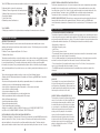
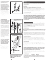
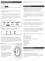
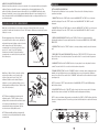
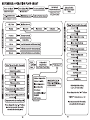
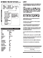
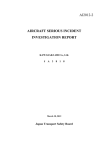
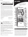
00992 INST06-06-08
Instruction Manual
Please DO NOT return product to the retail store.
For technical assistance and product return information, please call
Customer Care: 877-221-1252 Mon. - Fri. 8:00 A.M. to 4:45 P.M. (CST)
Professional WIreless Weather Station
With Wind Sensor & Atomic Clock
www.chaneyinstrument.com
LIMITED ONE YEAR WARRANTY
Chaney Instrument Company warrants that all products it manufactures to be of good material and workmanship and to be free of
defects if properly installed and operated for a period of one year from date of purchase. REMEDY FOR BREACH OF THIS
WARRANTY IS EXPRESSLY LIMITED TO REPAIR OR REPLACEMENT OF DEFECTIVE ITEMS. Any product which, under normal use
and service, is proven to breach the warranty contained herein within ONE YEAR from date of sale will, upon examination by
Chaney, and at its sole option, be repaired or replaced by Chaney. In all cases, transportation costs and charges for returned
goods shall be paid for by the purchaser. Chaney hereby disclaims all responsibility for such transportation costs and charges.
This warranty will not be breached, and Chaney will give no credit for products it manufactures which shall have received normal
wear and tear, been damaged, tampered, abused, improperly installed, damaged in shipping, or repaired or altered by others than
authorized representatives of Chaney.
MODEL # 00992
THE ABOVE-DESCRIBED WARRANTY IS EXPRESSLY IN LIEU OF ALL OTHER WARRANTIES, EXPRESS OR IMPLIED, AND ALL
OTHER WARRANTIES ARE HEREBY EXPRESSLY DISCLAIMED, INCLUDING WITHOUT LIMITATION THE IMPLIED WARRANTY OF
MERCHANTABILITY AND THE IMPLIED WARRANTY OF FITNESS FOR A PARTICULAR PURPOSE. CHANEY EXPRESSLY DISCLAIMS
ALL LIBILITY FOR SPECIAL, CONSEQUENTIAL OR INCIDENTAL DAMAGES, WHETHER ARISING IN TORT OR BY CONTRACT FROM
ANY BREACH OF THIS WARRANTY. SOME STATES DO NOT ALLOW THE EXCLUSION OR LIMITATION OF INCIDENTAL OR
CONSEQUENTIAL DAMAGES, SO THE ABOVE LIMITATION OR EXCLUSION MAY NOT APPLY TO YOU. CHANEY FURTHER DISCLAIMS
ALL LIABILITY FROM PERSONAL INJURY RELATING TO ITS PRODUCTS TO THE EXTENT PERMITTED BY LAW. BY ACCEPTANCE
OF ANY OF CHANEY’S EQUIPMENT OR PRODUCTS, THE PURCHASER ASSUMES ALL LIABILITY FOR THE CONSEQUENCES
ARISING FROM THEIR USE OR MISUSE. NO PERSON, FIRM OR CORPORATION IS AUTHORIZED TO ASSUME FOR CHANEY ANY
OTHER LIABILITY IN CONNECTION WITH THE SALE OF ITS PRODUCTS. FURTHERMORE, NO PERSON, FIRM OR CORPORATION IS
AUTHORIZED TO MODIFY OR WAIVE THE TERMS OF THIS PARAGRAPH, AND THE PRECEDING PARAGRAPH, UNLESS DONE IN
WRITING AND SIGNED BY A DULY AUTHORIZED AGENT OF CHANEY. THIS WARRANTY GIVES YOU SPECIFIC LEGAL RIGHTS, AND
YOU MAY ALSO HAVE OTHER RIGHTS WHICH VARY FROM STATE TO STATE.
For in-warranty repair, please contact:
Customer Care Department
Chaney Instrument Company
965 Wells Street
Lake Geneva, WI 53147
Exit
Chaney Customer Care 877-221-1252
Mon-Fri 8:00 a.m. to 4:45 p.m. CST
www.chaneyinstrument.com
This device complies with part 15 of the FCC rules. Operation is
subject to the following two conditions:
1- This device may NOT cause harmful interference, and
2- This device must accept any interference received, including
interference that may cause undesired operation.
NOTE: This equipment has been tested and found to comply with the limits for a
CLass B digital dvice, pursuant to Part 15 of the FCC rules. These limits are
designed to provide reasonable protection against harmful interference in a residential installation.
This equipment generates, uses and can radiate radio frequency energy and, if not installed and used
in accordance with the instructions, may cause harmful interference to radio communications.
However, There is no guarantee that interference will not occur in a particular installation. If this
equipment does cause harmful interference to radio or television reception, which can be determined
by turning the equipment off and on, the user is encouraged to try to correct the interference by one or
more of the following measures:
•Reorient or relocate the receiving antenna.
• Increase the separation between the equipment and the receiver.
• Connect the equipment into an outlet on a circuit different from that to which the
receiver is connected
• Consult the dealer or an experienced radio/TV technician for help.
NOTE: The manufacturer is not responsible for any radio or TV interference caused by unauthorized
modifications to this equipment. Such modifications could void the user authority to operate the
equipment.
Patent numbers: 5,978,738; 6,076,044; 6,597,990
INTRODUCTION
Thank you for purchasing the ACURITE® professional wireless weather station with
wind sensor & atomic clock. This unit is designed and engineered for everyday use in the
home, office or wherever weather is of interest. Your new weather station will provide
accurate and reliable measurement of wind speed and direction, air pressure, humidity
and temperature. The wireless weather station also includes an atomic clock, which
receives its signal from the National Institute of Standards and Technology government
operated atomic clock in Fort Collins, Colorado. This unit also comes with unique
features like wind chill, heat index and dew point calculations. Please read this manual
carefully to fully explore the features and benefits of your new weather station.
3
WIRELESS THERMO-HYGROMETER ATOMIC CLOCK SENSOR:
The thermo-hygrometer atomic clock sensor measures the outdoor temperature and relative
humidity. It also includes the radio controlled atomic clock transmitter, which receives data
from the atomic clock in Fort Collins, Colorado, and then sends the received data back to the
main unit display. The data is sent by a 433MHz radio controlled wireless transmission.
Transmission can be received up to 100 feet away in an unobstructed open area.
6
WIRELESS WIND SPEED SENSOR: The wind sensor measures wind speed and wind direction and
transmits this information to the main unit display. The data is sent by a 433MHz radio
controlled wireless transmission. Transmission can be received up to 100 feet away in an open
area.
The ACURITE® professional wireless weather station comes complete with the following items:
1. Main unit with foot stand for desktop use
2. Wireless Thermo-Hygrometer & mounting bracket
3. Wireless Wind speed sensor & mounting bracket
4. Instruction Manual
5. Quick Start Guide
6. Mounting screws & wall anchors
Exit
1
2
QUICKT
STAR
4
5
TOOLS NEEDED:
• Philips type screwdriver: for optional surface mounting of the wireless sensor / brackets.
OVERVIEW OF FEATURES
WEATHER STATION MAIN UNIT:
The main unit measures the indoor environment temperature and humidity and receives
weather and time data from the two outdoor wireless sensors. The following sensors send data
back to the main unit:
1. Wireless Thermo-Hygrometer/Atomic Clock Sensor
2. Wireless Wind Sensor
The wireless weather station receives the wireless sensor data continuously, updating you with
the latest and most accurate weather information on the large, easy-to-read LCD display, using
icons and trend indicators. The weather station main unit also provides you with weather
information, at-a-glance. Enjoy using the weather station either on the wall, using the hanging
slot by fastening with a nail or provided screw, or on a desktop, using the included snap-on foot
stand.
The professional wireless weather station is composed of the following features:
• Displays the NIST (National Institute of Standards and Technology) WWVB Radio Controlled
time and date
• Receives and displays weather data, with programmable alarms for certain weather
conditions, and records all minimum and maximum values
• Indoor/outdoor temperature in either Fahrenheit or Celsius (user selectable)
• Indoor/outdoor relative humidity
• Air pressure reading in Hg or hPa
• Weather forecast with weather icons and trend indicators
• Wind speed and wind direction display with LCD compass
• Wind chill temperature display
• Heat index temperature display
• Dew point temperature display
• Time, temperature and storm alarms
• Buttons for use: MAX (+), MIN (-), DISPLAY (daily record), CLEAR, PRESSURE SET-UP
(on/off/record), ALARM, CHANNEL (off/wave), SNOOZE (alarm off)
NIST WWVB RADIO CONTROLLED ATOMIC SIGNAL DESCRIPTION:
The National Institute of Standards and Technology government operated WWVB atomic radio
signal, located in Fort Collins, Colorado, is the most accurate radio signal, used by television,
radio and military for the most split-second time and date information. The time and date
display on this weather station is based on the signal provided by the atomic clock in Colorado.
GETTING STARTED
MOUNTING AND PLACEMENT CONSIDERATIONS:
The wireless transmission distance from the thermo-hygrometer sensor and wind speed sensor
to the main unit in open space under ideal conditions is 100ft. Although the signal transmission
may travel through solid surfaces or objects, Try to place the wireless sensors and main unit in a
location with minimal obstructions. The following points should be avoided if possible.
• High density of large trees.
• High Radio frequency areas.
• Low-E Glass.
• Thick concrete, stone or brick.
• The main unit, thermo-hygrometer and wind speed sensors should not be mounted to metal
surfaces as this can reduce range of transmission.
• Prior to drilling mounting holes and permanently affixing any of the units, please ensure the
main unit con receive the signal from the remote sensors in the desired location.
• For best reception of the signal from the atomic clock in Fort Collins, Colorado, place the
sensor in a location with a direction towards Colorado.
• The WWVB signal will be obtained easiest in the nighttime hours when the signal is the
strongest.
MOUNTING INSTRUCTIONS
MAIN UNIT:
The included foot mount can be attached to the
bottom of the main unit for easy placement on
any flat surface. Alternatively, the main unit can
be wall mounted in the desired location by using
the hang hole on the back of the unit.
WIRELESS THERMO-HYGROMEMTER SENSOR:
The best place to mount the thermo-hygrometer
sensor is in a location out of direct sunlight and
protected by extreme weather conditions, such
as under the extension of the home roof, under
a covered patio or deck. Mount the bracket that
the thermo-hygrometer sensor will set in at
about eye level by using the four included
screws. Once the bracket has been properly
affixed in the desired location, place the sensor
in the bracket holder. The thermo-hygrometer
wireless sensor may also be mounted on a pole;
which is outlined in the section “OPTIONAL
POLE MOUNTING.”
Exit
Mount With
Arrow Pointing Up
MOUNTING THE WIRELESS WIND SPEED
AND WIND DIRECTION SENSOR:
Before permanently mounting the
wind speed bracket, make sure that
the wind-fan and wind-vane can rotate
freely without any disruption. Also
note that the wind speed sensor
bracket arm must be pointing north.
The wind speed sensor should be
positioned to allow the wind to flow
around the sensor unhindered from all
directions for the most accurate and
correct readings.
OPTIONAL POLE MOUNTING:
Both sensors are designed to mount in
two ways, either to flat surfaces like
wood posts, or to 3/4” schedule 40
PVC pipe (the outside dimension of the
pipe actually measures approximately
1, 1/16”). The pipe mounting method is
often referred to in these instructions.
The ideal mounting scenario would be
for the wireless thermo-hygrometer to
be mounted on the north side of the
building and for the wind sensor to be
mounted well away from the building
and high in the air. Please test the
wireless signal range before permanently mounting.
Since PVC pipe is somewhat flexible, if
a tall wind sensor mast is being
erected, a larger diameter PVC pipe
should be used for the base with a
reducer fitting placed at the top.
Plastic pipes used for mounting are
non-conductive and reduce the
likelihood of lightening strikes.
BATTERIES (not included)
NOTE: Do not install batteries in any of the units until you have read through the initial set-up
steps in their entirety.
BATTERY TYPE:
INDOOR UNIT: “AA” (3) alkaline type batteries can be used for the indoor unit.
WIRELESS OUTDOOR UNIT (S): It is recommended that LITHIUM type “AA” batteries be used in any
outdoor units when the tempe0rature drops below -4ºF. Alkaline batteries will freeze at very low
temperatures and will fail to provide adequate power to the wireless units.
MAIN UNIT BATTERY REPLACEMENT:
When the low battery indicator icon becomes present, it is recommended that you change the
batteries. Replace only with the same or equivalent type of fresh alkaline batteries. This method
of battery replacement ensures there will be no loss in MIN/MAX and history data. However, if
the main unit or sensors have remained without batteries for an extended period of time, the
main unit will lose the MIN/MAX memory and all other weather data recordings and will have to
be synchronized again.
BEFORE INSTALLING BATTERIES:
Before you install the batteries in the main unit, you will need to have the altitude at which the
unit will be operating at ready to enter. This step cannot be skipped or returned to during the
initial set-up. Visit www.topozone.com, consult your local library or call our customer service
department at 877-221-1252 for altitude information.
BATTERY INSTALLATION:
For the first installation, insert the batteries into the two WIRELESS SENSORS FIRST and then into
the main unit.
Thermo-Hygrometer Sensor: Rotate and pull the top casing from the bottom cone by turning the
unit upside down and rotating counter-clock wise until casing pulls apart. Insert 2 fresh alkaline
“AA” batteries (batteries not included). Replace the battery compartment cover and rotate the
top back into the bottom piece.
Wind Sensor: Twist off the top from the bottom and open the battery cover located on the
bottom of the sensor. Insert 2 fresh alkaline “AA” batteries. (Batteries not included. Replace
battery door cover by putting battery cover on half way and then sliding into place. Twist on the
top to the bottom piece.
Main Unit: Open the battery cover located on the back of the unit. Remove the screw set
provided for wall mount use and insert 3 fresh alkaline “AA” batteries. (Batteries not included).
Replace battery door cover.
NOTE: When reinstalling the batteries while holding down the “CLEAR” button, all user settings
will be cleared and the unit will set back to the factory default settings. If no button is pushed
during battery replacement, the last record and user settings will be saved.
NOTE: When installing batteries, always install according to the polarity indicated in the battery
compartment ( + to + and - to - ).
LOW BATTERY INDICATOR:
LOW Battery
Battery O.K.
Low battery indicator is displayed on the main unit for the main unit and all wireless sensors.
When replacing the batteries, please follow the battery installation procedure as mentioned in
this instruction manual.
INITIAL SET-UP
GENERAL SET-UP
IMPORTANT:
For initial set-up, you will need to have the altitude at which the unit will be operating at ready to
enter. This step cannot be skipped or returned to during the initial set-up. Visit
www.topozone.com, consult your local library or call our customer service department at
877-221-1252 for altitude information.
The general setting mode allows the user to change several product default settings, which is
done by simply accessing one setting after the other by pressing the “PRESSURE SET-UP”
button. In normal mode, press and hold the “PRESSURE SET-UP” button for 3 seconds to enter
the manual set-up mode. The icon to set will be blinking. If no key is pressed for 30 seconds, the
manual set-up mode returns to the normal display mode. The general programming takes the
user through the modes listed below.
POWER ON:
1. Once the batteries have been inserted into the wireless sensors, they will automatically begin
transmitting data.
2. IMPORTANT: If you have already installed batteries into the main unit, please remove and
re-install to begin initial set-up.
3. Now that the main unit is on, it will show full display for 5 seconds then immidiately go into
“setting the altitude & forecast mode.”
NOTE: The main unit will stay in the altitude and forecast setting mode for 30 seconds before
automatically defaulting back into normal operation mode. The altitude and forecast set-up is
only available once during initial set-up/initial power up. If this step is missed, simply remove the
batteries and start over.
SETTING THE ALTITUDE AND FORECAST:
The pressure data area will show the default altitude data (300) and the altitude measurement
type will be blinking (FEET).
1. Press the “MAX” (+) or “MIN” (-) button to select your altitude measurement type in either
METER or FEET. To complete and move to the next step, press the “PRESSURE SET-UP” button.
2. The default altitude will now be blinking, using the “MAX” (+) or “MIN (-) buttons to set your
local altitude. The weather station has a range of -100 to 2500 meter (or from -330 to 8250
feet). To complete and move to the next step, press the “PRESSURE SET-UP” button.
3. The weather forecast icon will now be blinking. Adjust the weather forecast icon using the
“MAX” (+) or “MIN” (-) buttons until the forecast icon matches your current weather conditions.
Press the “PRESSURE SET-UP” button to confirm or press the “EXIT” button to exit the initial
set-up mode.
SIGNAL RECEPTION:
OUTDOOR WIRELESS SENSORS: As soon as the main unit is powered up, it will begin to search for
the outdoor wireless sensor signals. While in search mode, the WAVE icon will be animated.
During this time, all of the outdoor values will be shown as “---“ until the weather data has been
received correctly. When the wireless sensor and the main unit battery icons appear, a signal is
being received. To force a signal search, press and hold the “CHANNEL” button for 3 seconds.
RADIO CONTROLLED ATOMIC CLOCK:
The Radio Controlled Clock (RCC) signal from Fort Collins, CO is relayed through the wireless
thermo-hygrometer sensor. If the RCC signal has successfully been received, “ ” will be
displayed. If the RCC signal has not been received, only the icon “ ” will be displayed and
always blinking. If the signal has not been received successfully, the reception icon will be
blinking, the WAVE icon will be visible, but the OK icon will disappear. To force a signal search,
press and hold the “CHANNEL” button for 3 seconds.
While in the set-up mode, use “MAX” (+) or “MIN” (-) buttons to adjust the blinking values. Press
and hold for rapid scrolling through of the values. Press the “EXIT” button to exit the set-up
mode.
1. Manual time setting (hours/minutes), if atomic time is not available.
2. Calendar setting (month/date/year).
3. Time zone setting (P/M/C/E) (Note: zone will be blinking to the right of the WAVE icon).
a. P = Pacific Standard Time
b. M = Mountain Standard Time
c. C = Central Standard Time
d. E = Eastern Standard Time
4. Daylight Saving Time setting (ON or OFF)
DST ON = Daylight Saving Time enabled.
DST OF = Daylight Saving Time disabled.
5. Temperature unit setting (ºC or ºF)
6. Wind speed unit setting (mph/kph/knots)
7. Air pressure unit setting (mbar/hPa/inHg).
SELECTABLE DISPLAY MODES:
The following information options can be displayed on the main unit above the digital wind
direction compass. Press the “DISPLAY” button to toggle between the below weather data
information.
WIND CHILL: Wind chill is the rapid cooling of the human body caused by air motion. Air motion
accelerates the rate of heat transfer from a human body to the surrounding atmosphere,
especially when temperatures are low. The wind chill is a calculation of temperature data from
the wireless thermo-hygrometer remote sensor and the wind sensor.
HEAT INDEX:
Heat index is the perceived temperature to the human body based on both air temperature and
the amount of moisture present in the air. The heat index is a calculation based on the
combined temperature and humidity data received from the wireless thermo-hygrometer
remote sensor.
DEW POINT:
The dew point temperature is the temperature to which the air must be cooled to reach
saturation. The dew point is a calculation of temperature and humidity data received from the
wireless thermo-hygrometer remote sensor.
GENERAL WEATHER STATION FUNCTIONS
After the initial and general set-up, the following data will be displayed in different sections on
the main unit display.
MOON PHASE:
The moon phase indicator, found under the date display, shows the current phase of the moon
based on the yearly calendar.
CALENDAR FUNCTION: The calendar display, found under the time display shows the current
month and date with day indicator.
FORECAST ICONS: The main unit predicts weather conditions for the next 12 – 24 hours based
on the change in atmospheric pressure. The coverage area is up to 25 miles. Weather
forecasts based on atmospheric pressure changes are about 70-75% correct. As weather
conditions cannot be 100% correctly forecasted, we cannot be responsible for any loss caused
by an incorrect forecast.
One of the following icons will represent the 24 hr. weather forecast :
Wind Speed Average: The wind speed average is calculated by averaging the wind speed over a
period of time.
WEATHER AND TIME ALARMS
ALARM SETTING MODE: The alarm setting mode allows the user to change several alarm
settings, which is done by accessing one mode after the other, simply by pressing the
“ALARM”” button. The individual alarm can be turned on and off by using the
“ON/OFF/RECORD” button. When an alarm goes off, an audible tone will sound for one minute.
Press and hold the “ALARM” button for 3 seconds to enter the alarm setting mode. The time
display and “AL” for alarm will be blinking. This indicates the user is now in the alarm-setting
mode. In alarm setting mode, to activate or deactivate any alarm, press the “PRESSURE
SET-UP” button.
For non-time alarms, the blinking “HH.H” means the high alarm value is to be set.
For non-time alarms, the blinking “LL.L” means the low alarm value is to be set.
While in the alarm mode, use “MIN” (-) or “MAX” (+) buttons to change any of the values. Press
and hold for rapid scroll through of any values. Press the “EXIT” button to exit any of the
above alarm modes. Press the “ALARM” button to stop the alarm for one day, or press the
“SNOOZE” button to turn the alarm time off for five-minute increments.
TREND INDICATORS: Trend indicators for outdoor temperature and humidity and wind speed
show the trend tendency based on the past and current weather conditions.
BAROMETRIC BAR GRAPH AND PRESSURE HISTORY: The main unit shows BAROMETRIC pressure
in two forms, numerically and as a pressure history graph. The graph indicates the pressure
changes (range from +0.24inHg to -0.24inHg/ -8hPa mb to +8 hPa mb) of the current and past
1,2,3,6 and 12 hours. The numerical read out can be referenced backwards hour by hour for the
past 19 hours by pressing the “PRESSURE SET-UP” button.
WIND FUNCTIONS:
Digital Compass: The digital compass indicates
the direction from which the wind is coming from,
marked by the arrow indicator, with 16 possible
directions. The wind direction is shown here
coming out of the WEST.
Wind Gusts: The wind gust values are located in
the center of the digital compass. The wind gusts
are transmitted from the wind sensor and are
updated approximately every minute. The wind
gust shown here is 4 (mph).
This weather station also comes equipped with a audible storm alarm. When activated, the
storm alarm will sound if there is a sudden or extreme drop in barometric pressure or if there
is a constant progressive drop in barometric pressure. NOTE: If no button is pressed for 30
seconds, the alarm setting mode returns to the normal display mode.
Pressing the “ALARM” button during the alarm-setting mode scrolls through the following
settings:
1. Time alarm setting (hours, minutes)
2. Indoor temperature alarm (high, low)
3. Indoor humidity alarm (high, low)
4. Outdoor temperature alarm (high, low, at the current channel)
5. Outdoor humidity alarm (high, low)
6. Wind chill alarm (low)
7. Heat index alarm (high)
8. Dew point alarm (high, low)
9. Wind speed alarm
10. Storm alarm
MINIMUM & MAXIMUM RECORD MODE
The “MIN/MAX” buttons provide the user with information about the minimum and maximum
values of today’s weather data. It also acts as an access mode for the daily and long-term
records, with the time and date of their recordings.
TO ACCESS THE MIN OR MAX VALUES (TODAY’S HIGH’S AND LOW’S):
Press the “MIN” or “MAX” button to display the corresponding highs or lows of the day. When
pressing the “MIN” button, the unit will show the minimum value for all the records in the
upper display window.
TO ACCESS THE MIN OR MAX VALUES (CONTINUED):
When pressing the “MAX” button, the unit will show the maximum value for all the records in
the upper display window. Values in the upper display window are as follows; Outdoor temperature, outdoor humidity, indoor temperature, indoor humidity, wind speed average, wind speed
gusts, the selectable display item and barometric pressure. Barometric pressure is displayed in
the lower display window.
NOTE: To show min/max values for wind chill, heat index, or dew point (the selectable display
area), the value of interest must first be displayed by pressing the “DISPLAY” button until the
desired value is displayed.
DAILY RECORDS:
The Daily Record is a feature that displays a single value with the date and time of its recording.
When the daily record is being displayed, the value, date and time will be blinking. When the
unit is in a daily record mode, the unit will display a blinking “dr” next to the time of the
recording, indicating Daily Record. The main unit automatically stores the last seven days worth
of recordings.
TO ACCESS THE DAILY RECORDS:
While in either the “MIN” or “MAX” mode, press the “DAILY RECORD” button to show either the
“MIN” or “MAX” for any of the values shown in the graph below. Continue to press the “DAILY
RECORD” button to scroll through each of the values shown in the graph below.
To review the history of a blinking value, press the “-“ or “+” button to scroll backwards and
forwards within the last seven days of recordings. The value, date and time will update to show
when the record occurred.
NOTE: While reviewing the history for a certain value, pressing the “DAILY RECORD” button
automatically returns the unit to the present-day next value as shown in the graph below.
NOTE: Pressing the “exit” button at anytime, returns the unit to normal operating mode.
NOTE: Daily records can not be cleared; they automatically adjust on the seven day cycle.
TO ACCESS THE LONG-TERM RECORDS:
While in either the “MIN” or “MAX” mode, press the “RECORD” button to show the long-term
record highs or lows of the weather station. These values may have occurred anytime in the
history of the weather station. These values show the highest or lowest values ever recorded on
the weather station.
To review long-term records, press either the “MIN” or “MAX” button, then press the
“ON/OFF/RECORD” button to show the highest or lowest value, at this point, the unit will display
a blinking “Lr” in the second’s window and the unit will show all the record values. To obtain the
historical details for these records, press the “ON/OFF/RECORD” button and the record, along
with time and date will be blinking. Press the “ON/OFF/RECORD” button again to scroll through
each of the unit’s minimum and maximum record values.
CLEARING LONG-TERM RECORDS:
To clear long-term records, press either the “MIN” or “MAX” button, then press the
“ON/OFF/RECORD” button, at this point, the unit will display a blinking “Lr” in the second’s
window and the unit will show all the record values. Press the “CLEAR” button to clear all the
minimum or maximum values. All Long-Term records are cleared at once. This feature is most
often used at the beginning or end a of a given season Pressing the “exit” button at anytime,
returns the unit to normal operating mode.
MAINTENANCE
Clean the housing and screen of the base station only with a soft damp cloth. Do not use
abrasives or solvents. Do not submerge in water.
• Clean the outer housing of the thermo-hygrometer sensor with a soft damp cloth. Do not use
abrasives or solvents. Do not take sensor apart. Do not clean funnel of sensor. Do not submerse
sensor under running water.
• Clean the wind speed and direction sensor only with a soft damp cloth. Do not take sensor
apart. Do not use abrasives or solvents. Do not submerge in water.
• Should there be damage to any part of main unit and/or sensors, do not attempt to repair, as
this will result in loss of any manufacturer guarantee. Please send damaged part(s) to manufacture for repair/replacement. Manufacturer information is located at the end of this user manual.
GENERAL CARE OF MAIN UNIT AND WIRELESS SENSORS:
• Avoid exposing main unit and wireless sensors to extreme temperatures, keep out of direct
sunlight away from water or severe shock.
• When the outside temperature falls below -4ºF, the batteries in the wireless sensors may not
produce enough current to power the transmitter, if this happens, the main unit will not show
an outdoor temperature reading. We recommend the thermo-hygrometer wireless sensor be
brought indoors during prolonged periods of sub-freezing temperatures.
CHANGING BATTERIES
MAIN UNIT BATTERY REPLACEMENT: When the low battery indicator icon becomes present, it is
recommended that you change the batteries. Replace only with the same or equivalent type of
fresh alkaline batteries. This method of battery replacement ensures there will be no loss in
MIN/MAX and history data. However, if main unit or sensors have remained without batteries
for an extended period of time, the main unit will lose the MIN/MAX and all weather data
recordings and will have to be synchronized again.
NOTE: When replacing batteries, do not mix battery types or old batteries with new ones.
WIRELESS SENSOR BATTERY REPLACEMENT:
When the low battery indicator icon becomes present, it is recommended that you change the
batteries. Replace only with the same or equivalent type of fresh alkaline batteries. This
method of battery replacement ensures there will be no loss in MIN/MAX and history data.
However, if main unit or sensors have remained without batteries for an extended period of
time, the main unit will lose the MIN/MAX and all weather data recordings and will have to be
synchronized again.
REFERENCE
BUTTON OPERATION DESCRIPTIONS:
The main unit has 8 buttons for user operation. Please refer to the following for button
operation description:
ACCESSING THE BATTERY COMPARTMENTS
1. MIN BUTTON: Press the “MIN” button to enter the MIN MODE. The “MIN” icon on the main
unit will be displayed. Press the “EXIT” button to exit the MIN MODE. The “MIN” icon will
disappear.
Main Unit: Open the battery cover located on the back of the unit. Remove the screw set
provided for wall mount use and insert 3 fresh “AA” batteries. (Batteries not included). Replace
battery door cover.
2. MAX BUTTON: Press the “MAX” button to enter the MAX MODE. The “MAX” icon on the main
unit will be displayed. Press the “EXIT” button to exit the MAX MODE. The “MAX” icon will
disappear.
Top Casing
Thermo-Hygrometer Sensor: Rotate and pull the
top casing from the bottom cone by turning the
unit upside down and rotating counter-clock wise
until casing pulls apart. Slide the battery
compartment cover (located on the side of the
sensor) off. Insert 2 fresh “AA” batteries
(batteries not included). Replace the battery
compartment cover and rotate the top back into
the bottom piece.
Battery
Door
Batteries
4. CLEAR BUTTON: Press the “CLEAR” button to clear any settings currently stored in the main
unit.
5. PRESSURE SET-UP (ON/OFF/RECORD) BUTTON: Press the “PRESSURE SET-UP” button to view
the past 19 hours of recorded air pressure. Press and hold for 3 seconds to enter the general
set-up mode.
Bottom Cone
Wind Sensor: Twist off the top from the bottom
and open the battery cover located on the
bottom of the sensor. Insert 2 fresh “AA”
batteries. (Batteries not included). Replace
battery door cover by putting battery cover on
half way and then sliding into place. Twist on the
top to the bottom piece.
3. DISPLAY (DAILY RECORD) BUTTON: Press the “DISPLAY” button to toggle between the
following information in the upper right hand side of the main unit: WIND CHILL, HEAT INDEX,
DEW POINT.
6. ALARM BUTTON: Press the “ALARM” button to stop any alarm for one day when the alarm
sounds. Press and hold for 3 seconds to enter the alarm set-up mode.
Top Casing
Battery
7. CHANNEL (EXIT) BUTTON: Press the “CHANNEL” button to view the outdoor temperature and
humidity for any additional sensors used. Additional sensors are sold separately. Additional
sensors are optional. Press and hold the “CHANNEL” button will force the main unit into signal
searching mode.
NOTE: Pressing the “EXIT” button will exit all of the MIN/MAX, SET-UP, and ALARM settings
while in these modes.
8. SNOOZE BUTTON: Press the “SNOOZE” button to enter into the snooze mode for 5 minutes
when the time alarm is activated. The ALARM icon will be displayed and blinking.
NOTE: When reinstalling the batteries while
holding down the “CLEAR” button, all user
settings will be cleared and the unit will set back
to the factory default settings. If no button is
pushed during battery replacement, the last
record and user settings will be saved.
NOTE: When installing batteries, always install
according to the polarity indicated in the battery
compartment.
Battery
Door
Bottom Casing
Battery
NOTE: In set-up and alarm setting mode, pressing either the “MIN” or “MAX” buttons will allow
the user to change any values. The user may press and hold the button for rapid scroll through
of values.
REFERENCE: FACTORY DEFAULT SETTINGS
MODEL# 00594W
Do not return product to retail store. For Technical Assistance and
product return information, please contact Customer Care at:
877-221-1252
HOURS: Monday through Friday from 8:00 a.m. to 4:45 pm CST.