1
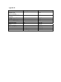
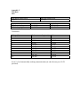
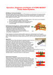
Platoon of Autonomous Vehicles
Mid-Project Report
12.13.2003
Sponsored by
Dr. Richard Wall and Dr. Joseph Feeley
Advised by
Dr. Richard Wall
Team Members
Thomas DuBuisson, Philip Gregg,
Jesse Lorenzen, Jesse Schauer
Abstract
1.0 Project Description
1.1 Problem Statement
1.2 Solution Method
2.0 Status
2.1 Designed and Working
2.2 Designed and Not Working
2.3 Designed and Not Tested
3.0 Method of Solution
3.1 Technical Description
3.2 Theoretical Basis
4.0 Validation Procedure
5.0 Results
5.1 Operation Procedure
5.2 Validation Results
5.3 Cost Analysis
6.0 Appendix A-C
Abstract
The goal is to create a set of vehicles that will search for objects with in a specified area.
Vehicles are organized in a leader and follower format with up to five vehicles. Each
vehicle will have the capability of being the leader. The vehicles carry a suite of
instrumentation for communications, object detection, and navigation. Communications
use Maxstream 9xStreams and are operational. Garmin GPS-16’s are used in navigation
and are operational. Polaroid 6500 sonic range finders will be used in object detection;
the final few bugs are being worked out. The vehicles will travel at up to 2 miles per
hour except when required for object avoidance, vehicle turning, and search patterns. The
vehicles are expected to run for over two hours.
1.0 Project Description
1.1 Project Definition
A fleet of vehicles is to sweep an area looking for objects. The vehicles will be organized
in a platoon fashion with one leader and up to four followers. The robust design must
allow any vehicle to become the platoon leader should the leader become incapacitated.
Each vehicle will carry an instrumentation suite including GPS for navigation, ultrasonic
rangefinders and infrared detectors for obstacle avoidance, and communications
transceivers for control and mapping data.
1.2 Objectives
Our Objective is to construct a fleet of five autonomous vehicles that will sweep a
rectangular area, looking for objects. The vehicles will move in a formation that allows
the area to be searched efficiently. The coordinates of located objects will be reported
back to the base station so a list of all objects in the search field can be created.
1.3 Specifications
• Each vehicle must be capable of becoming the lead vehicle should the current lead
vehicle be disabled.
• Each vehicle must be capable of avoiding objects in its path.
• Each vehicle must be capable of communicating with all other vehicles and the base
station.
• Each vehicle must be able to detect objects with dimensions between 10” x 10” x 10”
and 72” x 72” x 72” and record it’s coordinates.
• Each vehicle must be capable of storing the location of several discovered objects.
• The vehicles must be able to locate all objects in a 100 x 40 yard rectangle.
• Each vehicle must travel 10 ± 1 ft from the next vehicle when in formation.
1.4 Deliverables after completion of project
• Five autonomous vehicles
• Control program and transceiver for base station
• Code for autonomous vehicles and control program
• Documentation for vehicle construction
• User Manual
• Final Report
1.5 Constraints
• All objects to be detected must be stationary.
• The search area must be a flat regular surface with 10 yards of traversable space on all
sides.
• Environmental temperature must be between 32° and 92° Fahrenheit.
• Environmental humidity must be less than 70%.
• There must be sufficiently low levels of interference to allow the communications, GPS
and other wireless components to function properly.
2.0 Status
All modules have a design. Figure 1 shows which modules have been fully implemented,
partially implemented, and no implementation. Modules are only labeled as fully
implemented if it is believed that no further work will be needed to be done.
Figure 1: Data Flow Graph
SRF
Position
Arbitration
Hall
Effect
Green-Complete
Yellow - Some Implementation Complete
Red - Implementation not yet started
Navigation
GPS
DB
Communications
Coordinate
Sharing
Send
Parser
Receive
Parser
Group
Status
2.1 Designed and Working
Communications, LCD, GPS, interrupts and the I2C interface with the servo controller
are all implemented and functioning properly. The group status module meets the design;
any future changes will be a result of a desire for different behavior. The receive parser
lacks the supporting functions for the individual message types; this will be fixed once
the modules ment to handle each of the message types exist. Further details on each of
these can be found in section 3.0.
2.2 Designed and Not Working
The power circuit, based on the LC1076, is not yet working. If this continues to be a
problem a quick solution could be getting the LC1076-5 which can operate as needed
without extra circuitry. Sonic range finders have worked in the past; the last few bugs are
being worked out.
2.3 Designed but not tested
The modules navigation and coordinate sharing have been designed but are not yet
implemented and/or tested. The sensor layout has been designed but has not yet been
constructed. The database has been designed and implemented but is in need of rigorous
testing.
3.0 Method of Solution
3.1 Communications
The communication system uses MaxStream 9XSTREAM wireless modules. These
modules are attached to serial port D and have a maximum data rate of 9600 bps.
Currently, four modules make use of the communications: transport layer, group status
monitoring, send packing and parsing, and receive parsing. These modules work together
to: ensure there is a commander, share AV locations, discover when an AV fails, and
ensure no collisions occur.
Figure 1: Message Paths
Modules
Receiving
Messages
Receive
Parsing
Transport
Layer
Modules
Sending
Messages
Send
Parsing
Receive parsing reads the message types (as defined by msg_types.lib), extracts the
message and deals with the message accordingly. This can be either calling another
function or changing a global variable.
Send parsing will package as many messages waiting in the message queue (a linked list)
as can fit into a packet and send the packet off, then repeat the process. If on a
subordinate, send parser will relinquish control of the communications media when it has
sent the maximum allowed number of messages or there are no more messages to send.
Send parser will never automatically relinquish control of the communications media
when running on the commander.
As a subordinate, the group status module will reply to the commander whenever he
requests a report. If the commander give the subordinate the token (signaling control of
the communications media) the send parser will then be invoked. The group status
module also has a commander watchdog; if the commander has not sent a message within
a specified amount of time then he is declared dead and the subordinate claims command.
To avoid many subordinates claiming command at the same time each subordinate sets
its watchdog timer a set time plus a multiple of its address. As a leader the group status
module will send out self reports, allow send parser to package and send any queued
messages, request reports, and declare other AVs dead.
3.1.2 Communications Encapsulation
The packets appear as in figure 3. This protocol is named Light Weight Protocol (LWP).
Figure 3: Packet fields and sizes (in bits)
Length
5
Flags
3
Dest
4
Source
4
Payload and Padding
224
CRC
16
LWP has an address space of sixteen, payload up to twenty eight bytes, three flags (only
one of which is used - for the token), and reasonable error detection. To assist in
simulating the Ultra Sonic modem communications are always in multiples of 32 bytes.
3.2 Control
The servo being used is a DS-SCX8S capable of controlling up to eight servos. The I2C
communication to the servo controller is working. The servo operates as expected.
3.3 Sensors
The working sensor systems are: GPS, sonic range finders. For GPS we are using the
Garmin GPS16. It is connected to serial A and provides coordinates as well as time. For
sonic range finders we have three Polaroid 6500s per AV. These sensors do not
automatically calculate the distance to a located target; they are thus hooked up to the
external interrupt and the time from echo to interrupt is measured and used to calculate
the distance to target.
3.4 Data Handling and Structures
Most data sharing is done by variable passing. The global variables are in stdvars.lib.
The main global variables are: structures defining AV properties, the commanders’
address and the communications token.
3.5 Interrupts
Timer B and External Interrupt are both working. Timer B interrupts every 80
milliseconds to regularize the sonic range finders ping. External Interrupt is used when
the sonic range finders receive an echo.
3.6 Object Database
The object database (db.lib) is a dually linked list containing the location of all known
objects. Objects communicated from other vehicles are added to the head. Objects
located by the current AV are added to the tail. Objects added to the head are stored for
purposes of redundancy. Objects added to the tail must either come after or be pointed to
by the Coordinate Sharing pointer (CSptr). The coordinate sharing module (cs.lib – not
yet implemented) will call on the database for a list of new data items needed to be
communicated; this lookup is facilitated by the CSptr (see figure 2).
Due to the range finders pinging every 80ms the same object will be seen multiple times.
When the range finder module adds a new object location it might specify that the object
is being stored for navigation purposes only. A flag is set in the cell to indicate this fact
and the location will not be given to the coordinate sharing module; the location will be
deleted as soon as the navigation routine is informed of the object location. Navigation
receives object locations in the same way as the coordinate sharing module.
Figure 2: Object Database
Head
CSptr
NAVptr
Tail
The algorithm to add an object is O(N); this is because memory can not be dynamically
allocated. All possible cells are contained in an array and it is necessary to traverse
through the array to find a free cell to add to the list. This would degrade system
performance as more objects are added to the list. To fix this problem a linked list of
empty cells will be created. When objects are deleted the old cell will be added to the list
of empty cells. When objects are added an empty cell is taken from this list. This makes
adding objects an O(1) algorithm. All of this database except for the list of empty cells is
implemented but not tested.
3.7 Navigation and Control
The AV search pattern and broken unit recovery follows:
1) Vehicles start in or drive to form a horizontal line on one corner of the field.
2) Vehicles drive from one end to another.
Leader
3) Vehicles turn around at the other end to scan the next row of the field.
Leader
4) The above steps are repeated except in a breakdown. If a unit breaks then the outer
most unit will take up the broken vehicles position and the other units will stop until back
in half wing formation.
Leader
When turning after such an event (3) the turn will be sharper such that the leader ends up
traveling the row that was being covered by the outer vehicles before the 2nd vehicle
broke. If the outer most vehicle breaks then no vehicle will alter course, the next turn
will just be sharper as to allow the leader to travel down the row the broken vehicle was
on.
5) Once the search is complete the units travel back to the known coordinates for base
station.
3.8 Object Coordinate Sharing
Each AV will keep track of a hash of the coordinates most recently communicated to it
by each of the other vehicles. Upon checking with the commander, they compare their
hashes with those of the commanders. If any set of coordinates was missed then those
coordinates can then be communicated to the AV from the commander who has been
maintaining a set of the most recent object coordinates. In the event the commander
missed a set of coordinates he will be informed by the AV of the missed communication
the next time that AV sees the commanders hash set (at next roll call). This system will
not tolerate an AV missing a coordinate and the commander dying in the same round.
3.9 GPS
For position detection and clock initialization, we are using the Garmin GPS16. The
GPS16 is attached the rabbit through Serial Port C, which is operating at 4800 baud. With
the unit, we can update the AV’s position once per second. The GPS coordinates give us
a general idea of the location of the AV, but are only accurate to within 3 m.
Furthermore, the second delay between when we can poll introduces further error.
The secondary purpose of the GPS unit is clock initialization. The AVs can request the
current time and date (UTC) and set their internal clock to match this. This allows the
AVs clocks to be somewhat synchronized.
Aside from positioning and clock synchronization, the GPS library will contain functions
to determine GPS satellite visibility and bearing.
3.10 Velocity Determination
Because the GPS is only updated once per second, it’s velocity measurements cannot be
used to adjust the speed of the vehicle accurately. Instead, we have constructed a
tachometer system for the AVs. The tachometer uses a DN6848-ND hall effect sensor to
detect neodymium magnets affixed to the AV’s wheels. Supporting hardware includes a
74LS157 4-bit 2-to-1 multiplexer and a CD4024BC 7-bit binary counter. The tachometer
device is connected to parallel port B pins PB2-7.
hall sensor
Rabbit
2300
74LS157
4-bit 2-1 mux
CD4024BC
7-bit counter
Each time the hall sensor detects a magnet, the counter is incremented. When the rabbit
polls the counter, it first reads the lower 4 bits of the count, then reads the upper four bits.
These are added together to give a total count. This count is then used to calculate
velocity in cm/s using the following formula:
(π * wheel diameter * # of counter ticks / # of magnets) * 1000 / time elapsed in ms
Currently the system is implemented with 6 magnets. We plan to add more magnets in
the future to improve the reliability of the tachometer reading.
3.11 LCD
To assist with debugging and to display status messages, we have attached a character
LCD to the AV. We are using a Hitachi HD44780 compatible LCD because they are
cheap and easy to acquire. Our current LCD is a 16x1 model, but we may use a 16x2 in
the future.
The LCD interfaces with the Rabbit through the lower 6 bits of parallel port D. We are
using a modified version of the LCD sample code provided with the Dynamic C 8.10 dev
kit. This code uses a 4-bit interface to save on I/O pins. It allows users to clear the display
and display a 16-character message any time after the LCD has been initialized.
3.12 Others
IR sensors will be placed on the AVs and used for navigation when close to obstacles.
The Physical sensor layout has yet to be tested. It is estimated that the SRFs will be
placed facing 15º left, forward, and 15º right. All SRFs will be placed facing ~8º up to
avoid excessive ground feedback.
4.0 Validation Procedure
4.1 GPS
To test the GPS, we created a test program. This program output the one of five things to
the LCD:
1. Link Validity
2. Current Latitude
3. Current Longitude
4. Current Date
5. Current Time
We took the development kit (with attached GPS and LCD) to the parking lot between
BEL and EP. Once the link became valid, we viewed the GPS coordinates and recorded
some of them. These coordinates were compared to the coordinates given for Moscow,
ID to see if they are within Moscow. We also checked to see if the latitude would
increase if we walked north.
To test the time functionality of the GPS, we ran the setClock procedure while the GPS
link was valid. By default, the Rabbit’s real-time clock is off by several days. Running
the setClock procedure should change the date to show the correct day.
4.2 Tachometer
To test the tachometer, we wrote a program that would display the tachometer’s speed on
the LCD. We connected an AV’s motor to a lab power supply. The input voltage to the
motor was varied between 0V and 10V DC in 1V increments, and the tachometers output
was recorded. The variance exhibited in the output value was also recorded.
4.3 LCD
To test the LCD, we attempted to display several different string on the LCD. Strings of
various length between 1and 16 were used.
4.4 Sonic Rage Finders
The initial SRF tests involved connecting one to a function generator and oscilloscope to
get an understanding of how the signals behave in different situations. Different objects
at different angles and distances were placed in front of the SRF. The next test was to
develop a microcontroller program to control one SRF and display the distances to the
screen. The next test will use three sensors and simulate the use of SRF’s once placed
on the AV’s.
4.5 IR Sensors
Due to a shipping error we received analog IR detectors instead of digital detectors, we
did perform tests to determine the general scope of the detectors, but were unable to fully
test the detectors without extra hardware.
4.6 Communications
The MaxStreams were initially tested by connecting a Maxstream to a rabbit
microprocessor programmed to broadcast a single message. An oscilloscope was used to
check on Rabbit-Maxstream communication. After ensuring the setup was operational
AV.c was made which tested to following modules: transport layer, group status, receive
parsing, and send parsing.
4.7 Interrupts
AV.c was then modified to enable Timer B. A timer B routine was designed to print out
a message every 13*80ms = 1.04 seconds. Credit: The timer B interrupt routine was
written by Shdesigns and placed in public domain. Please see the credits in the source
code.
5.0 Results
5.1 Operation procedures
5.1.0 GPS
The GPS must be connected to serial port C. A 6-pin header exists on the Rabbit
development board for the GPS to connect to. For the GPS to operate correctly, it must be
outdoors, and be able to see a reasonable portion of the sky.
Before any of the GPS’ functionality may be used, it must be initialized. This is done by
calling the gps_init function. gps_init opens serial port C and sets the value for the null
GPS value gnull.
To get a new GPS position, the function update_gps_pos is called. This should be called
no faster than 1 time a second, as the GPS only updates once per second. This function
will return a new GPS coordinate if it can get a valid signal, or will return the gnull
otherwise.
To synchronize the Rabbit’s internal real-time clock with UTC, the function setClock is
called. Calling set clock will read a GPS sentence and try to set the RTC to the sentence’s
time. If it is successful, a 0 is returned. Otherwise, setClock returns a nonzero value.
To determine if there is a valid GPS link, the function gps_valid may be called. This
function will grab a GPS sentence and determine if the signal is valid. The function
returns 1 if the signal is valid, 0 otherwise.
5.1.1 Tachometer
The tachometer must be connected to parallel port B, pins 3-7. A 8-pin header for the
tachometer exists on the Rabbit development board for the tachometer daughter board to
connect to. For the tachometer to operate correctly, the hall sensor must be positioned
within 1.25cm of the surface of the current neodymium magnets. The detector may be
closer, but if it is too close, the magnets may strike the hall sensor, leading to inaccuracy
or damage to the sensor.
Before the tachometer is first used, it must be initialized. This is done by calling the
tach_Init function. This sets the control lines to the tachometer so that it will begin to
count pulses.
To get velocity from the tachometer, the function tach_speed may be called. Tachometer
speed polls the tachometer and calculates velocity. The velocity is returned as a floating
point value. tach_speed should not be called too often; the more often it is called, the
more variance is introduced to the speed measurement. Polling once every half second
with 6 magnets gives acceptable readings.
5.1.2 LCD
The LCD must be attached to the lower 6-pins of parallel port D. A 14-pin header for the
LCD exists on the Rabbit development board. Pin 3 of this connector may be attached
either to ground, or to a potentiometer between power and ground to control the LCD’s
contrast.
Before the LCD can be used, it must be initialized. This is done with the LCD_Init
function. LCD_Init sets up the LCD into 4-bit mode with a non-blinking cursor.
To write to the LCD, the function Display_LCD is used. Display_LCD takes a character
string (16 characters or less) and displays it to the LCD. Currently, if more than 16
characters are in the string, the characters over 16 will be displayed over the second 8
characters. This will be adjusted to truncate the string.
When Display_LCD is called, it will continue to write from the last place that was
written. Under most circumstances, this is unwanted, so Clear_LCD must be called. This
clears the screen and returns the cursor to the first position.
5.2 Validation results
5.2.0 GPS
The GPS validation tests show that the GPS appears to be working. the coordinates
received at the BEL stairs landing were 46.43908N, 117.00610W.
http://www.epodunk.com/cgi-bin/genInfo.php?locIndex=7009 gives the latitude and
longitude for Moscow, ID as 46.732N, -116.999W. This is close, though the sign on our
longitude is wrong. It appears that we are not reading signs for coordinates. On the scale
that we are operating, however, this is not important.
By moving the GPS from the BEL stairs landing to the stop sign near BEL on 6th St, we
get the new coordinates 46.43923N, 117.00594W. We moved NE, and this data shows
that we did.
5.2.1 Tachometer
The tachometer tests showed that as the input voltage to the AV’s motor was increased,
the tachometer reading increased. The relationship between tachometer reading and input
voltage appears to be nearly linear. Since these tests were done with no load on the
wheels, a linear relationship is what we should be getting.
Voltage vs. Tach Reading
500
400
cm/s
300
200
100
0
-100 0
2
4
6
8
10
12
Voltage
The variance between the most prominent tachometer reading at a particular voltage and
the occasional higher one is very consistent. At any particular voltage level, there is a
possible variance of approximately 12.6 cm/s. This variance occurs because 12.6 cm is
our wheel diameter and we are taking our readings twice each second while using 6
magnets. If we assume the variance is caused by occasionally getting an extra tick, the
variance equation is:
(π * wheel diameter / # of magnets) * 1000 / time elapsed in ms
Substituting our values into this equation gives us:
(π * 12.6 / 3)
π is nearly equal to 3, and thus they more or less cancel out, giving us our diameter for
the variance.
5.2.2 LCD
We tried displaying several strings to the LCD. All of them displayed correctly.
5.2.3 Communications
The MaxStreams did not operate properly when connected to serial port B. This is due to
a misunderstanding of the Maxstream interface (0-5 volts as opposed to RS232).
Rewiring the Maxstream to use serial port D resulted in proper communications.
5.3 Cost Analysis
5.3.1 Project Overview
The project is to design an equivalent testing platform to an autonomous underwater
vehicle. Since many UAV’s cost more then this project’s entire budget this is a costeffective modeling technique.
5.3.2 Rabbit microcontrollers
The Rabbit microcontrollers were a specification of the customer. We could have bought
modules and made our own development boards. However, when the time to develop the
new board & designing the support hardware would have made this project take
significantly longer then the time available. Also, the production of boards would have
exceeded the cost of Rabbit Semiconductor’s development boards.
5.3.3 Maxstream Radios
The Maxstream was selected because it was the least expensive and the most effective
solution available. Using 802.11b was suggested but the cost was $100 dollars a unit
more and the range was significantly less.
5.3.4 Panasonic 12v Batteries
The batteries selected weigh 5lbs and supply 7.2 amp hours at 12 volts. At $20 a unit
including shipping, this was the most power for the least cost.
5.3.5 Hummer Vehicles
The Hummer vehicles are 1/10th scale Hummers build by Nikkon. They were purchased
from Toys R’ US for $60.00 a unit. This is compared to the $270.00 a unit for a custom
chassis with better components. In this instance it was necessary for us to trade design
and building time for lesser cost.
5.3.6 Garmin GPS LV15
The decision to go with the Garmin LV15 was because we already had two units and to
switch to any other would cost more and provide little or no benefit.
5.3.7 Infrared Sensors
By going with the selected infrared sensors we will cut the overall hardware overhead by
being given a simple digital signal.
5.3.8 Power regulator
LT1076, a standard power regulator to step 12V to 5V. All other components where of
similar cost.
5.3.9 Maxim RS232CPE
The recommended serial interface chip for the Rabbit 2300.
5.3.10 Polaroid 6500 Sonar
All other similar units were in the same price range. We selected the Polaroid because it
had the highest quality signal return. Other units made by Devantech would have had the
easiest interface.
Appendix A: Specifications
For additional information see the specifications folder on the AV CD provided.
Board Layout
Appendix B
Item
Rabbit 2300
Microcontroller
Maxstream 900MHZ Serial
Modems
12V Panasonic Batteries
1/10th scale hummers
Garmin GPS LV15
Infrared Sensor
1076
Maxim RS232
Polaroid 6500 Sonar
Quantity
4
Cost
$676
5
$539
5
5
3
10
5
4
12
Total
Total Budget
$102.90
$315
$525
$105.00
$32.50
$13.34
$531.35
$2840.05
$4000.00
Appendix C
Test Data
GPS
Date before setting clock
12/6/03
BEL Stairs landing
BEL/6th Stop Sign
Date after setting clock
12/11/03
Latitude
46.43908N
46.43923N
Longitude
117.00610W
117.00594W
Tachometer
Voltage (V)
0
1
2
3
4
5
6
7
8
9
10
Tachometer reading (cm/s)
0
0
37.989
88.640
151.954
189.579
240.594
291.245
341.241
391.796
454.988
Variance
0
0
12.662
12.860
12.347
12.638
12.177
12.081
12.639
12.638
13.536
See AV.c for demonstratibly working communications (in code directory on AV CD
provided).