1
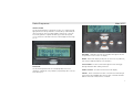
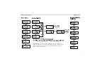
Pocket Programmer
UPB Pocket Programmer
User Guide
Model UPP
Pocket Programmer
DESCRIPTION
The Pocket Programmer (model UPP) provides many of the features
of UPStart UPB configuration software in a portable hand held device.
The Pocket Programmer comes with a handy carrying case and AC
power cord that plugs into any standard receptacle allowing
communication to installed UPB devices. The Pocket Programmer is
intended for use by an installer who is familiar with UPStart and UPB
products. It virtually eliminates the need to have a PC with UPStart
software and a Computer Interface Module (CIM) at every jobsite. It
makes configuring UPB devices from room to room, quick and easy.
The UPP may be used instead of UPStart to provide initial
configuration steps such as adding devices to a UPB network or
disabling dimming allowing a newly installed switch to operate a
fluorescent fixture. It could also be used to program an entire UPB
installation. No data is stored in the UPP. The UPB network and
device programming is stored in each UPB device. A UPB network
that was configured with the UPP may be added to UPStart at any
time by using the Network Discovery feature in UPStart. The UPP
has diagnostic tools that include a noise and signal meter and an
explorer feature that reads and transmits UPB messages on the
powerline. In the Run CIM mode the Pocket Programmer may be used
as a Computer Interface Module.
Model UPP
IMPORTANT SAFETY INSTRUCTIONS
When using electrical products, basic safety precautions should
always be followed, including the following:
1. READ AND FOLLOW ALL SAFETY INSTRUCTIONS.
2. Keep away from water. If product comes into contact with
water or other liquid, unplug immediately.
3. Never use products that have been dropped or damaged.
4. Do not use this product outdoors.
5. Do not use this product for other than its intended use.
6. To avoid risk of fire, burns, personal injury and electric
shock, install this product out of reach of small children.
7. Do not cover the product with cloth, paper or any material
when in use.
8. This product uses polarized plugs and sockets (one blade is
wider than the other) as a feature to reduce the risk of
electric shock. These plugs and sockets fit only one way. If
they do not fit, contact a qualified technician. Do not use
with an extension cord unless plugs can be fully inserted.
Do not alter or replace plugs.
9. SAVE THESE INSTRUCTIONS.
-2-
Pocket Programmer
Model UPP
INSTALLATION
The Pocket Programmer is designed for indoor use. Simply plug the
appropriate end of the provided AC cord into the top of the UPP, the
other end into any 120-volt outlet anywhere in the house. Once the
Pocket Programmer completes its start up procedure the top two
(of six) selections of the main menu are on the display and it is ready
for use.
UP
MENU
LEFT
ENTER
RIGHT
DOWN
BUTTONS: The buttons provide easy navigation through the Pocket
Programmer’s menus on the LCD display.
MENU: Returns the display to the previous menu from any sub-menu,
exits selection without writing to selected device.
FUNCTION
The Pocket Programmer has an LCD display with 2 lines of 16
characters, a diagnostic LED, 7 buttons, a polarized power connector
and a DB-9 port.
UP and DOWN: Provide movement through the menus and toggle
through characters when editing a selection.
RIGHT and LEFT: Provide movement across the display.
ENTER: Enters a selected menu item. Provides movement through
selected menu item editable fields, and executes commands and edits
that are sent to the selected device or network.
3
Pocket Programmer
FUNCTION: Toggles the backlight on the LCD display.
LED: The diagnostic LED operates
just as the LED on the Computer
Interface Module. In Run CIM mode
the Pocket Programmer exchanges
UPB messages between the powerline
and the connected computer or
controller. The indicator on the UPP
will glow AMBER when powered, flash
RED when UPB messages are seen on
the power line and flash GREEN when a UPB message is transmitted
from the Pocket Programmer.
DB9 Port: Connect a standard serial cable to an RS-232 port to use
the Pocket Programmer as a Computer Interface Module. The DB9
port may also be used to upgrade the firmware in the UPP.
MENU NAVIGATION
Pressing the <MENU> button backs out of a selection without making
changes. Pressing <ENTER> opens the menu selection and submenus. Some menus require the use of the <UP>/<DOWN> and
<RIGHT>/<LEFT> buttons to edit characters and move the cursor
position.
Model UPP
USING THE POCKET PROGRAMMER
The pocket programmer mirrors the functionality of UPStart
Configuration software. If the installer is familiar with UPStart then
most of the UPP menus and functions are intuitive and easy to use. If
there are any questions or difficulties in using the UPP referencing the
specific function in the UPStart software is highly recommended. The
pocket programmer identifies device by Device ID number, device
names are not used. It is highly recommended that the User knows
(has created a list or plan for) the device’s ID when programming. A
device’s ID can ‘Viewed’ by putting the device in setup mode then use
the pocket programmer to View the device from the Access Network
sub-menu.
UPDATING THE POCKET PROGRAMMER
The Pocket Programmer was designed with the future in mind. As new
UPB devices become available the UPP will need to have its program
updated to allow use with these new devices.
To update your UPP, please visit www.Simply-Automated.com/UPPUPDATE and follow the instructions. A personal computer with a
connection for a DB9 serial cable is required.
4
Pocket Programmer
Model UPP
Access Network is used on an installed UPB network. It is useful when
viewing or editing devices. Devices can be added or deleted. Links may also be
added or deleted. The same functions are available in UPStart under the
Device, Link and Network menus.
5
Pocket Programmer
New Network
Model UPP
1)Access
Network
1
2)New Network
<DOWN>
<MENU>
1)Access Network
2
2)New Network
<ENTER>
New Network is used to create a UPB network by starting with a Network ID and
Password. The Network ID can be from 1 – 250. It is recommended to use a
different Network ID for each installation. The password is 4 hexidecimal
characters, 0 – 9 and A – F. Once the UPB network is created devices and Links
may be added. Nothing is stored in the UPP. All data is stored in the devices as
they are added. UPB device must share the same UPB Network ID and password
to communicate peer to peer.
<MENU>
Select Net ID=001
<UP>
Select Net ID=002
<UP>
To desired
Network ID
<ENTER>
Select Net ID=001
<Search for Net>
<MENU>
Select Net ID=001
Select Pswd=0000
<UP> Select Net ID=001
Select Pswd=1000
<RIGHT>
Select Net ID=001
Select Pswd=1000
Continue until
desired
Password
<ENTER>
<MENU>
1)Add Device
1
2)Edit Device
<ENTER> to Add Device (See Add Device page)
<DOWN> to scroll through this sub-menu (See Access Network Sub-Menu)
6
Pocket Programmer
Model UPP
Add Device is used to add installed
UPB devices to the UPB network.
If a device is not found:
1. Make sure there is only
one device in set up mode.
2. Check the wiring to ensure
the connections are proper
and the wire nuts are on
tight.
3. Check the phase coupler to
ensure it is properly
installed and operational.
7
Pocket Programmer
Model UPP
Edit Device is used to change the
settings on a previously added
device. For instance, the dimming
can be disabled under the Options
sub-menu.
-8-
Pocket Programmer
Model UPP
9
Pocket Programmer
Model UPP
10
Pocket Programmer
Model UPP
Edit Device Sub-Menu – Transmit Links
1)ID
1
2)Receive Links
<UP/DOWN>
1)ID
2
2)Receive Links
<ENTER> <Reading Device>
<UP/DOWN>
2)Receive Links
3)Transmit Links
3
01)Link=241
<MENU> 0
Super Toggler
<UP/DOWN>
Super Toggler
<UP/DOWN>
...
08)Link=--Super Toggler
<ENTER>
3)Transmit Links
4)Options
4
<MENU>
01)Link=241
Super Toggler
<UP/DOWN>
01)Link=242
Super Toggler
Field rolls over.
Range is 001 to 250
<UP/DOWN>
01)Link=241
On/Off Button
Choices as Down Button is pressed:
Super Toggler
Link Actuator
Toggle Button
Drape Close
Super Multi-Button
Drape Open
Multi-Button
Null Button
Panic Button
BtmSuperRocker
Bottom Rocker
TopSuperRocker
Top Rocker
Indicator Off
Dim Button
Indicator On
Bright Button
Status Button
On Button
On/Off Button
Off Button
<ENTER>
<UP/DOWN>
4)Options
5
5)Advanced
01)Link=241
Super Toggler
<MENU>
1)Add Device
1
2)Edit Device
<UP/DOWN> 02)Link=---
<ENTER>
01)Link=241
<Writing>
11
Pocket Programmer
Model UPP
12
Pocket Programmer
Model UPP
1)ID
1
2)Receive Links
Edit Device - Advanced
<UP/DOWN>
1)ID
2
2)Receive Links
<UP/DOWN>
2)Receive Links
3
3)Transmit Links
<UP/DOWN>
<ENTER>
1)Xmit Type:
1
2)Xmit Atmpts:
<ENTER> Transmit Type=
1)Xmit Type:
2
2)Xmit Atmpts:
<ENTER>
2)Xmit Atmpts:
3
3)Xmit
2 Rpeatr:
<ENTER>
Link
<UP/DOWN>
Transmit Type=
Direct
<MENU>
<ENTER>
<Writing>
3)Transmit Links
4
4)Options
<UP/DOWN>
TX Attempts=2
<UP/DOWN>
1 to 4
<MENU>
<ENTER>
<Writing>
4)Options
5
5)Advanced
<MENU>
1)Add Device
1
2)Edit Device
Xmit to Repeatr:
No Repeater
<UP/DOWN>
Xmit to Repeatr:
Repeater, Tx=1
<MENU>
<ENTER>
<Writing>
<UP/DOWN>
Tx=1 to 3
13
Pocket Programmer
1)Add Device
1
2)Edit Device
<ENTER>
Model UPP
View Device
View is Read Only
<MENU>
View Device is used to check the
current settings of a UPB device.
Settings can be observed but not
changed.
1)Add Device
2
2)Edit Device
<ENTER>
<MENU>
2)Edit Device
3)View Device
3
<ENTER>
Select DevID=001
<MENU>
<UP>
Select DevID=002
To desired
Device ID
<UP>
<ENTER>
Select DevID=001
<SAI UML>
ELSE Err:
Device Not Found
If device is not found
<ENTER>
<MENU>
1
1)ID
2)Receive Links
<UP/DOWN>
<ENTER>
Go to Edit/View
Device Sub-Menu
1)ID
2
2)Receive Links
<UP/DOWN>
2)Receive Links
3)Transmit Links
3
<UP/DOWN>
3)Transmit Links
4)Options
4
<UP/DOWN>
4)Options
5
5)Advanced
14
Pocket Programmer
Model UPP
Add Link
1)Access
Network
1
2)New Network
<ENTER>
Add Link is used to create and add
a Link to one or more UPB devices.
<MENU>
Select Net ID=001
<UP>
Select Net ID=002
<UP>
To desired
Network ID
<ENTER>
<MENU>
Select Net ID=001
Select Pswd=0000
<UP>
Select Net ID=001 <RIGHT> Select Net ID=001
Select Pswd=1000
Select Pswd=1000
Continue until
desired
Password
<ENTER>
1)Add Device
1
2)Edit Device
<DOWN>
1)Add Device
2
2)Edit Device
<MENU>
Enter Setup Mode
Add Link=001
<DOWN>
<UP/DOWN>
To Select Device ID
2)Edit Device
3
3)View Device
Device that is to have the Link added
must be in Setup Mode.
This feature will work with multiple
devices as long as all are in Setup Mode.
<ENTER>
<DOWN>
<Link Added>
Add Link=001
3)View Device
4
4)Delete Device
<ENTER>
<MENU> or <ENTER>
This will display even if no
device was put in Setup
Mode, hence no Link added.
<DOWN>
4)Delete Device
5
5)Add Link
15
Pocket Programmer
Model UPP
.
16
Pocket Programmer
Model UPP
UPB Explorer – Smart Transmit
1
1)Access Network
2)New Network
<ENTER>
<UP/DOWN>
1
1)Smart Transmit
2)Smart Receive
<UP/DOWN>
1)Access Network
2)New Network
2
1)Smart Transmit
2)Smart Receive
2
<UP/DOWN>
<UP/DOWN>
2)New Network
3
3)UPB Explorer
<MENU>
2)Smart Receive
3
3)Expert Receive
<UP/DOWN>
3)Expert Receive
4
4)Expert Transmit
Smart Transmit is used test
communications of Links or control
of devices.
<ENTER> Select Type=LINK
<UP/DOWN>
Select Type=DIRCT
<ENTER> Select Type=Link
Select NetID=001
<UP/DOWN>
To select
Network ID
<UP/DOWN>
To select
Link ID
<ENTER>
Link = 001
1)Activate
<ENTER>
Link = 001
1)Activate
<UP/DOWN>
Link = 001
2)Deactivate
.
.
.
Link = 001
9)Blink
<ENTER> Link = 001
<Sent>
1)Activate
2)Deactivate
3)Goto ON
4)Goto OFF
5)Goto <ENTER> 050%
6)Fade UP/STOP
7)Fade DOWN/STOP
8)Fade STOP
9)Blink
(Goto <ENTER> allows selection of level
with <UP/DOWN> buttons. Fade UP/
STOP and Fade DOWN/STOP brighten
or dim while holding the <ENTER> button
and stop upon release).
17
Pocket Programmer
Model UPP
.
Smart Receive is used to observe
UPB transmissions.
18
Pocket Programmer
Model UPP
.
19
Pocket Programmer
Model UPP
Simply Automated, Incorporated
5825 Avenida Encinas, Suite 101, Carlsbad, CA 92008 USA
Technical Support: www.simply-automated.com or 800-630-9234
452-0031-0001 Rev. A Revised: May 16, 2006
20