1
®
powerware
Prestige Series
3000 VA, 200-240V
Installation and Operator’s Manual for IBM Applications
Requesting a Declaration of Conformity
Units that are labeled with a CE mark comply with the following harmonic standards and EU directives:
:
:
Harmonic Standards: EN 50091-1-1 and EN 50091-2
EU Directives:
73/23/EEC, Council Directive on equipment designed for use within certain voltage limits
93/68/EEC, Amending Directive 73/23/EEC
89/336/EEC, Council Directive relating to electromagnetic compatibility
92/31/EEC, Amending Directive 89/336/EEC relating to EMC
The EC Declaration of Conformity is available upon request for products with a CE mark. For copies of the EC
Declaration of Conformity, contact:
Powerware Corporation
Koskelontie 13
FIN-02920 Espoo
Finland
Phone: +358-9-452 661
Fax: +358-9-452 665 68
Class A EMC Statements
FCC Part 15
NOTE This equipment has been tested and found to comply with the limits for a Class A digital device, pursuant to
part 15 of the FCC Rules. These limits are designed to provide reasonable protection against harmful interference when
the equipment is operated in a commercial environment. This equipment generates, uses, and can radiate radio frequency
energy and, if not installed and used in accordance with the instruction manual, may cause harmful interference to radio
communications. Operation of this equipment in a residential area is likely to cause harmful interference in which case
the user will be required to correct the interference at his own expense.
ICES-003
This Class A Interference Causing Equipment meets all requirements of the Canadian Interference Causing Equipment
Regulations ICES-003.
Cet appareil numérique de la classe A respecte toutes les exigences du Reglement sur le matériel brouilleur du Canada.
EN50091-2
Some configurations are classified under EN50091-2 as “Class-A UPS for Unrestricted Sales Distribution.” For these
configurations, the following applies:
WARNING This is a Class A-UPS Product. In a domestic environment, this product may cause radio interference, in
which case, the user may be required to take additional measures.
Powerware, PowerPass, Powercare, OnliNet, and OnliSafe are registered trademarks of Powerware Corporation.
IBM and AS/400 are registered trademarks of International Business Machines Corp.
Novell is a registered trademark of Novell, Inc.
3Com is a registered trademark of 3Com Corporation.
.
Copyright 1997-2000 Powerware Corporation, Raleigh, North Carolina, USA. All rights reserved. No part of this
document may be reproduced in any way without the express written approval of Powerware Corporation.
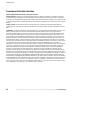
QUICK INSTALL
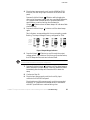
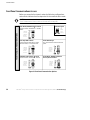
UPS with PPDM Quick Installation
1
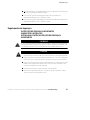
If you are connecting the UPS to an AS/400, the QUPSDLYTIM system value for the UPS
Monitoring feature should be set. See “UPS Monitoring” on page 52 for instructions.
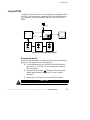
2
UPS
Cabinet
Battery
Cabinet
PowerPass
Distribution
Module
(PPDM,)
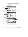
3
Bypass Switch
(NORMAL Position)
Quick Install
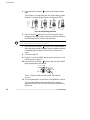
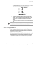
4
I
I
ON
ON
OFF
O
Battery
Breaker
,
21
OFF
O
5
6
The UPS output voltage is factory-configured for 230V. If you need to change the output
voltage, see “UPS with PPDM Startup” on page 42.
7
For the AS/400 interface, plug the AS/400 communications cable into the serial port on the
UPS rear panel. Plug the other end of the cable into the J14 connector or the connector
labeled “UPS” on your AS/400.
8
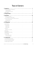
TABLE OF CONTENTS
1 Introduction . . . . . . . . . . . . . . . . . . . . . . . . . . . . . . . . . . . . . . . . . . . . . . . . . . . . 1
UPS Model and Battery Configurations . . . . . . . . . . . . . . . . . . . . . . . . . . . . . . . . . . . . . . . . . . . . . .
Load Requirements . . . . . . . . . . . . . . . . . . . . . . . . . . . . . . . . . . . . . . . . . . . . . . . . . . . . . . . . .
Approximate Battery Times . . . . . . . . . . . . . . . . . . . . . . . . . . . . . . . . . . . . . . . . . . . . . . . . . . . .
Special Symbols . . . . . . . . . . . . . . . . . . . . . . . . . . . . . . . . . . . . . . . . . . . . . . . . . . . . . . . . . . . . . .
2
2
3
5
2 Safety Warnings . . . . . . . . . . . . . . . . . . . . . . . . . . . . . . . . . . . . . . . . . . . . . . . . . 7
3 Installation . . . . . . . . . . . . . . . . . . . . . . . . . . . . . . . . . . . . . . . . . . . . . . . . . . . . . 35
Unpacking and Inspection . . . . . . . . . . . . . . . . . . . . . . . . . . . . . . . . . . . . . . . . . . . . . . . . . . . . . . .
UPS and Battery Cabinet Storage . . . . . . . . . . . . . . . . . . . . . . . . . . . . . . . . . . . . . . . . . . . . . . .
UPS with PowerPass Distribution Module Installation . . . . . . . . . . . . . . . . . . . . . . . . . . . . . . . . . . .
UPS with PPDM Startup . . . . . . . . . . . . . . . . . . . . . . . . . . . . . . . . . . . . . . . . . . . . . . . . . . . . . .
REPO Installation . . . . . . . . . . . . . . . . . . . . . . . . . . . . . . . . . . . . . . . . . . . . . . . . . . . . . . . . . . .
Troubleshooting Tips . . . . . . . . . . . . . . . . . . . . . . . . . . . . . . . . . . . . . . . . . . . . . . . . . . . . . . . . . . .
35
35
35
42
44
46
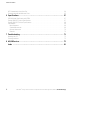
4 UPS Operation . . . . . . . . . . . . . . . . . . . . . . . . . . . . . . . . . . . . . . . . . . . . . . . . . . 47
UPS Front Panel . . . . . . . . . . . . . . . . . . . . . . . . . . . . . . . . . . . . . . . . . . . . . . . . . . . . . . . . . . . . . .
Operating Modes . . . . . . . . . . . . . . . . . . . . . . . . . . . . . . . . . . . . . . . . . . . . . . . . . . . . . . . . . . . . .
Normal Mode . . . . . . . . . . . . . . . . . . . . . . . . . . . . . . . . . . . . . . . . . . . . . . . . . . . . . . . . . . . . .
Bypass Mode . . . . . . . . . . . . . . . . . . . . . . . . . . . . . . . . . . . . . . . . . . . . . . . . . . . . . . . . . . . . .
Battery Mode . . . . . . . . . . . . . . . . . . . . . . . . . . . . . . . . . . . . . . . . . . . . . . . . . . . . . . . . . . . . .
Diagnostics . . . . . . . . . . . . . . . . . . . . . . . . . . . . . . . . . . . . . . . . . . . . . . . . . . . . . . . . . . . . . . . . .
Battery Test on Demand . . . . . . . . . . . . . . . . . . . . . . . . . . . . . . . . . . . . . . . . . . . . . . . . . . . . . .
Battery Start . . . . . . . . . . . . . . . . . . . . . . . . . . . . . . . . . . . . . . . . . . . . . . . . . . . . . . . . . . . . . . . .
UPS Shutdown . . . . . . . . . . . . . . . . . . . . . . . . . . . . . . . . . . . . . . . . . . . . . . . . . . . . . . . . . . . . . . .
Changing the Output Voltage . . . . . . . . . . . . . . . . . . . . . . . . . . . . . . . . . . . . . . . . . . . . . . . . . . . . .
UPS Monitoring . . . . . . . . . . . . . . . . . . . . . . . . . . . . . . . . . . . . . . . . . . . . . . . . . . . . . . . . . . . . . .
Using the PPDM . . . . . . . . . . . . . . . . . . . . . . . . . . . . . . . . . . . . . . . . . . . . . . . . . . . . . . . . . . . . . .
Disconnecting the UPS . . . . . . . . . . . . . . . . . . . . . . . . . . . . . . . . . . . . . . . . . . . . . . . . . . . . . . .
Reconnecting the UPS . . . . . . . . . . . . . . . . . . . . . . . . . . . . . . . . . . . . . . . . . . . . . . . . . . . . . . .
47
48
48
49
49
50
50
50
51
51
52
53
53
55
5 Communication . . . . . . . . . . . . . . . . . . . . . . . . . . . . . . . . . . . . . . . . . . . . . . . . . 57
Initial Communications Settings . . . . . . . . . . . . . . . . . . . . . . . . . . . . . . . . . . . . . . . . . . . . . . . . . . .
Front Panel Communications Access . . . . . . . . . . . . . . . . . . . . . . . . . . . . . . . . . . . . . . . . . . . . . . .
UPS Serial Communications Menu . . . . . . . . . . . . . . . . . . . . . . . . . . . . . . . . . . . . . . . . . . . . . . . . .
Power Management Software . . . . . . . . . . . . . . . . . . . . . . . . . . . . . . . . . . . . . . . . . . . . . . . . . . . .
Powerware® Prestige Series Installation and Operator’s Manual for IBM Applications (3000 VA) Uncontrolled Copy
57
58
60
63
i
Table of Contents
UPS Communications Interface Port . . . . . . . . . . . . . . . . . . . . . . . . . . . . . . . . . . . . . . . . . . . . . . . . 64
Communications Mode Reference Chart . . . . . . . . . . . . . . . . . . . . . . . . . . . . . . . . . . . . . . . . . . . . . 65
6 Specifications . . . . . . . . . . . . . . . . . . . . . . . . . . . . . . . . . . . . . . . . . . . . . . . . . . 67
3000 VA Model Specification with PPDM . . . . . . . . . . . . . . . . . . . . . . . . . . . . . . . . . . . . . . . . . . . .
Prestige 3000 UPS Physical Specifications . . . . . . . . . . . . . . . . . . . . . . . . . . . . . . . . . . . . . . . . . . .
Prestige 3000 UPS Technical Specifications . . . . . . . . . . . . . . . . . . . . . . . . . . . . . . . . . . . . . . . . . .
Part Numbers . . . . . . . . . . . . . . . . . . . . . . . . . . . . . . . . . . . . . . . . . . . . . . . . . . . . . . . . . . . . . . . .
Base Equipment . . . . . . . . . . . . . . . . . . . . . . . . . . . . . . . . . . . . . . . . . . . . . . . . . . . . . . . . . . .
Standard Accessories . . . . . . . . . . . . . . . . . . . . . . . . . . . . . . . . . . . . . . . . . . . . . . . . . . . . . . . .
Optional Accessories . . . . . . . . . . . . . . . . . . . . . . . . . . . . . . . . . . . . . . . . . . . . . . . . . . . . . . . .
Manuals . . . . . . . . . . . . . . . . . . . . . . . . . . . . . . . . . . . . . . . . . . . . . . . . . . . . . . . . . . . . . . . . .
67
67
68
69
69
69
70
70
7 Troubleshooting . . . . . . . . . . . . . . . . . . . . . . . . . . . . . . . . . . . . . . . . . . . . . . . . . 71
Resetting the UPS . . . . . . . . . . . . . . . . . . . . . . . . . . . . . . . . . . . . . . . . . . . . . . . . . . . . . . . . . . . . 73
Silencing the Alarm . . . . . . . . . . . . . . . . . . . . . . . . . . . . . . . . . . . . . . . . . . . . . . . . . . . . . . . . . . . 73
8 AS/400 Service . . . . . . . . . . . . . . . . . . . . . . . . . . . . . . . . . . . . . . . . . . . . . . . . . . 75
Index . . . . . . . . . . . . . . . . . . . . . . . . . . . . . . . . . . . . . . . . . . . . . . . . . . . . . . . . . 81
ii
Powerware® Prestige Series Installation and Operator’s Manual for IBM Applications (3000 VA) Uncontrolled Copy
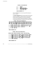
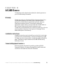
CHAPTER
1
INTRODUCTION
Congratulations on the purchase of your Powerware9 Prestige Series
uninterruptible power system (UPS). The Prestige UPS meets the
toughest measures of superior design and manufacturing, including
ISO 9001. You now own the most reliable power protection available.
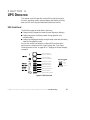
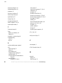
The Prestige 3000 provides a steady, well-regulated power supply for
your computing and communications equipment, while protecting it
from the frequent irregularities that are inherent in commercially
available power. Voltage spikes, power surges, brownouts, and power
failures have the potential to corrupt critical data, destroy unsaved work
sessions, and in some instances, damage expensive hardware.
With the Prestige 3000, you can safely eliminate the effects of electrical
line disturbances and guard the integrity of your systems and
equipment. The PowerPass9 Distribution Module (PPDM) has a
Maintenance Bypass feature that supplies power to your equipment even
when the UPS electronics are removed for maintenance or upgrades.
Figure 1 shows the Prestige 3000 UPS.
Figure 1. Prestige 3000 UPS
Powerware® Prestige Series Installation and Operator’s Manual for IBM Applications (3000 VA) Uncontrolled Copy
1
Introduction
UPS Model and Battery Configurations
This UPS is designed to work with single-phase, three-wire, AC power
sources. There are two important considerations when selecting the UPS
model and battery configuration to properly safeguard your equipment:
:
Load requirements
:
Battery times
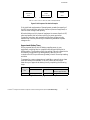
Load Requirements
The load is the equipment to be protected by the UPS. Select the UPS
model that meets the power consumption requirements of the load in
volt-amperes (VA). The total load VA should not exceed the UPS VA
rating. To determine the total load requirements:
1. Obtain the load ratings from either the nameplate or operator’s
manual of the equipment to be protected by the UPS. The
ratings are listed in either watts (W), amperes or amperes
max (A), or volt-amperes.
2. If the rating is in watts, multiply by 1.4 to obtain the VA
requirement (this is the typical relationship between watts and
volt-ampere ratings in most computing equipment). However,
in some new computing equipment, the power supply is
power-factor corrected and the watts rating equals the VA
requirement. Check with the manufacturer to determine
applicability.
If the rating is in amperes or amperes max, multiply by the
input voltage to obtain the VA requirement.
NOTE For the load ratings of AS/400 models and attachable devices, see Chapter 9 of
“AS/400 Physical Planning Reference,” SC41-5109.
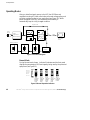
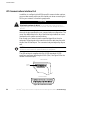
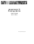
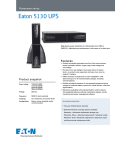
3. Add all of the resultant VA ratings together to obtain the total
load requirements of the equipment to be protected (see
Figure 2). If the load consists of the power-factor corrected
supplies, it is recommended to use total watts for the load
requirements.
2
Powerware® Prestige Series Installation and Operator’s Manual for IBM Applications (3000 VA) Uncontrolled Copy
Introduction
3 COMPUTERS
3 MONITORS
200 WATTS
EACH
1 AMP
EACH AT 240V
3 x 200 WATTS x 1.4 = 840 VA
3 x 1 AMP x 240 = 720 VA
EXTERNAL
MODEM
50 VA
50 VA
840 VA + 720 VA + 50 VA = 1610 VA (Total Load Requirements)
Figure 2. Volt-Amperes Calculation Example
If the total load requirements of the equipment exceeds the capacity of
the UPS, you must either reduce the number of pieces of equipment, or
use a UPS with a larger load capacity.
When deciding on which pieces of equipment to remove from the UPS,
select equipment that has a lower priority for power protection.
Computers, monitors, and modems typically have a higher priority
because they could be processing or transmitting data when a power
outage occurs.
Approximate Battery Times
During a power failure, the UPS battery supplies power to your
equipment, providing time to complete computing activities prior to
UPS shutdown. The duration of this time period is directly related to the
UPS battery configuration. By adding battery cabinets, you can
customize the UPS to provide enough battery time for normal processing
activities.
To prepare for a power outage at your installation, ensure that you have
sufficient battery time available. To do this, take a few minutes to
determine your approximate battery time by completing the following
steps:
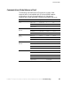
Load
Requirements
(VA)
Battery Time
UPS Model
Battery Cabinets
Total Battery Time
Minutes (Approximate)
Prestige 3000 (9910 EP5)
Figure 3. Determining Approximate Battery Time
Powerware® Prestige Series Installation and Operator’s Manual for IBM Applications (3000 VA) Uncontrolled Copy
3
Introduction
1. See “Load Requirements” on page 2 for assistance in
determining the total load requirements for your UPS. Round
this number up to the next Load (VA) entry in the following
table, “Prestige 3000 with PPDM,” and enter the number in
Figure 3.
2. In Figure 3, enter the number of battery cabinets that you
have installed. Find the intersection point of the appropriate
Load (VA) and number of battery cabinets in the following
table, “Prestige 3000 with PPDM.” Enter this number in
Figure 3, Total Battery Time Minutes.
If changes take place in your installation, such as different load
parameters or changes to battery cabinet configuration, take time to
reevaluate your approximate battery time availability.
NOTE For detailed information regarding calculation of 9910 UPS battery capacity and
run time for your load, reference: “AS/400 Physical Planning,” SA41-5109, “AS/400
Advanced Series Backup and Recovery - Advanced,” SC41-4305 (see Chapter 10), or
“AS/400e series Backup and Recovery,” SC41-5304 (see Chapter 37).
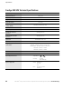
Prestige 3000 with PPDM
Approximate Battery Time (in Minutes)
Load (VA)
Load (W)
600
1 Cabinet
2 Cabinets
3 Cabinets
420
36.8
88
146
800
533
27.6
66
110
1200
800
18.4
44
73
1600
1067
13.7
33
54
2000
1333
10.7
26
42
2500
1667
8.3
20
33
3000
2000
6.5
16
27
NOTE For AS/400 usage, see “Base Equipment” on page 69.
4
Powerware® Prestige Series Installation and Operator’s Manual for IBM Applications (3000 VA) Uncontrolled Copy
Introduction
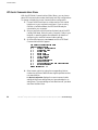
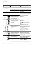
Special Symbols
The following common symbols may be found on the UPS:
LOAD ON - Press the button with this symbol to energize the
output receptacles (Output On).
LOAD OFF - Press the button with this symbol to de-energize
the output receptacles (Output Off).
SAFETY EARTHING TERMINAL - Indicates the primary safety
ground.
RISK OF ELECTRIC SHOCK - Indicates that a risk of electric
shock is present and the associated warning should be
observed.
CAUTION: REFER TO OPERATOR’S MANUAL - Refer to your
operator’s manual for additional information.
BYPASS - Indicates bypass control switches.
INPUT BREAKER - Indicates the input breaker, which shuts
off utility power to the UPS electronics.
BATTERY BREAKER - Indicates the battery breaker, which
shuts off battery power (power transmission through the
battery cord).
BATTERY CONNECTOR - Indicates the battery connector,
which remains electrically “hot” even with the battery
breaker off. Keep covered when not in use.
OUTPUT BREAKER - Indicates an output breaker.
Powerware® Prestige Series Installation and Operator’s Manual for IBM Applications (3000 VA) Uncontrolled Copy
5
Introduction
This page intentionally left blank.
6
Powerware® Prestige Series Installation and Operator’s Manual for IBM Applications (3000 VA) Uncontrolled Copy
CHAPTER
2
SAFETY WARNINGS
IMPORTANT SAFETY INSTRUCTIONS
SAVE THESE INSTRUCTIONS. This manual contains important instructions that you
should follow during installation of the UPS. Please read all instructions before
operating the equipment and save this manual for future reference.
DANGER
This UPS contains LETHAL VOLTAGES. All repairs and service should be performed
by AUTHORIZED SERVICE PERSONNEL ONLY. There are NO USER
SERVICEABLE PARTS inside the UPS.
CAUTION
:
Batteries can present a risk of electrical shock or burn from high short circuit
current. Observe proper precautions.
:
Proper disposal of batteries is required. Refer to your local codes for disposal
requirements.
:
This UPS contains its own energy source (batteries). The output receptacles may
carry live voltage even when the UPS is not connected to an AC supply.
:
Never dispose of batteries in a fire. Batteries may explode when exposed to flame.
:
Never open or mutilate batteries. Released electrolyte is harmful to the skin and
eyes, and may be extremely toxic.
:
Use only the power supply cord provided with this UPS. The power cord is wired in
accordance with National Electrical Code (NEC) specifications. Be sure the wall
outlet to be used with the UPS is wired in accordance with these same
specifications in order to avoid damage to your equipment. Be sure that
overcurrent protection for the AC outlet is provided at the time of installation. Be
sure the input plug is completely inserted into the wall outlet. Use a single-phase,
three-wire, grounded AC outlet only.
:
To reduce the risk of fire or electric shock, install this UPS in a temperature and
humidity controlled, indoor environment, free of conductive contaminants. Ambient
temperature must not exceed 104F (40C). Do not operate near water or
excessive humidity (95% max).
:
Do not remove or unplug the input cord when the UPS is turned on. This removes
the safety ground from the UPS and the equipment connected to the UPS.
Powerware® Prestige Series Installation and Operator’s Manual for IBM Applications (3000 VA) Uncontrolled Copy
7
Safety Warnings
:
To comply with international standards and wiring regulations, the total equipment
connected to the output of this UPS must not have an earth leakage current
greater than 2.75 milliamperes.
:
The wall outlet must be within 2 meters of the equipment and accessible to the
operator. The on/off switch on the UPS does not electrically isolate the internal
parts. Unplug the input cord from the wall outlet when disconnecting the unit for
long periods of time.
:
Please note that the output sockets on the UPS are electrically live whenever the
UPS Output On button is pressed, even if the input cord is disconnected.
:
For PowerPass systems with hardwired outputs, overcurrent protection for the
output AC circuit(s) is to be provided by others.
:
For PowerPass systems with hardwired outputs, suitably rated disconnect switches
for the output AC circuit(s) are to be provided by others.
Sikkerhedsanvisninger
VIGTIGE SIKKERHEDSANVISNINGER
GEM DISSE ANVISNINGER
DENNE BRUGERVEJLEDNING INDEHOLDER VIGTIGE
SIKKERHEDSANVISNINGER
FARE
Denne UPS indeholder LIVSFARLIG HØJSPÆNDING. Alle reparationer og
vedligeholdelse bør kun udføres af en AUTORISERET SERVICETEKNIKER. Ingen af
UPS’ens indvendige dele kan repareres af brugeren.
ADVARSEL
8
:
Batterier kan udgøre en fare for elektrisk stød eller forbrændinger forårsaget af høj
kortslutningsspænding. De korrekte forholdsregler bør overholdes.
:
Korrekt bortskaffelse af batterier er påkrævet. Overhold gældende lokale regler for
bortskaffelsesprocedurer.
:
Denne UPS indeholder egen energiforsyning (batterier). Udgangsnetstikkene kan
lede strøm, selv når UPS’en ikke er tilsat en AC-energikilde.
:
Skaf dig aldrig af med batterierne ved at brænde dem. Batterierne kan eksplodere
ved åben ild.
Powerware® Prestige Series Installation and Operator’s Manual for IBM Applications (3000 VA) Uncontrolled Copy
Safety Warnings
:
Batterierne bør aldrig åbnes eller skilles ad. Elektrolyt, der slipper ud, er skadelig
for hud og øjne og kan være overordentlig giftig.
:
Brug kun den netledning, som blev leveret med UPS’en. Denne netledning er
tilsluttet ifølge specifikationerne for NEC (National Electrical Code). Sørg for, at
stikket, som skal bruges til UPS’en, er tilsluttet ifølge de samme specifikationer for
at undgå skade på dit udstyr. Sørg for, at der er overstrømsbeskyttelse på
AC-stikket på monteringstidspunktet. Sørg for, at stikket er sat helt ind i
stikkontakten. Brug en enfaset, -treledet AC-kilde, som er jordet.
:
Installér denne UPS i et temperatur- og fugtighedskontrolleret indendørsmiljø, frit
for ledende forureningsstoffer for at formindske risikoen for brand og elektrisk
stød. Rumtemperaturen må ikke overstige 40°C. UPS’en bør ikke betjenes nær
vand eller høj fugtighed (maksimalt 95%).
:
Netledningen må ikke fjernes og stikket må ikke trækkes ud, mens UPS’en er
tændt. Dette fjerner sikkerhedsjorden fra UPS’en og fra det udstyr, der er sat til.
:
I overensstemmelse med internationale normer og bestemmelser for el-installation
må det udstyr, der er forbundet til udgangen af denne UPS, tilsammen ikke
overskride en jordafdelingsspænding på mere end 2,75 milliampere.
:
Stikkontakten må højst være 2 meter fra udstyret og tilgængelig for brugeren.
UPS’ens afbryderkontakt isolerer ikke elektrisk de indvendige dele. Træk derfor
stikket ud af kontakten, hvis enheden er slukket i lang tid ad gangen.
:
Bemærk venligst, at stikkontakterne på UPS’en er strømførende, når knappen UPS
“Output On” er trykket ned, selvom indgangsnedledningen ikke er tilsluttet.
:
Med hensyn til Bypass-systemer med direkte forbundne udgange, skal
overstrømsbeskyttelsen for AC-kredsen(e) komme andetsteds fra.
:
Med hensyn til Bypass-systemer med direkte forbundne udgange, skal
afbryderkontakter til AC-kredsløbet med passende mærkeeffekt komme andetsteds
fra.
Powerware® Prestige Series Installation and Operator’s Manual for IBM Applications (3000 VA) Uncontrolled Copy
9
Safety Warnings
Belangrijke Veiligheidsinstructies
BELANGRIJKE VEILIGHEIDSINSTRUCTIES
BEWAAR DEZE INSTRUCTIES
DEZE HANDLEIDING BEVAT BELANGRIJKE
VEILIGHEIDSINSTRUCTIES
GEVAAR
Deze UPS bevat LEVENSGEVAARLIJKE ELEKTRISCHE SPANNING. Alle reparaties en
onderhoud dienen UITSLUITEND DOOR ERKEND SERVICEPERSONEEL te worden
uitgevoerd. Er bevinden zich GEEN ONDERDELEN in de UPS die DOOR DE GEBRUIKER
kunnen worden GEREPAREERD.
OPGELET
10
:
Batterijen kunnen gevaar voor elektrische schok of brandwonden veroorzaken als
gevolg van un hoge kortsluitstroom. Volg de desbetreffende aanwijzingen op.
:
De batterijen moeten op de juiste wijze worden opgeruimd. Raadpleeg hiervoor uw
plaatselijke voorschriften.
:
Deze UPS bevat zijn eigen energiebron (batterijen). De uitgangsaansluitingen
kunnen onder spanning staan wanneer de UPS niet op een wisselstroom voeding is
aangesloten.
:
Nooit batterijen in het vuur gooien. De batterijen kunnen ontploffen.
:
Nooit batterijen openen of beschadigen. Vrijkomend elektrolyt is schadelijk voor de
huid en ogen, en kan uiterst giftig zijn.
:
Uitsluitend het elektriciteitssnoer gebruiken dat bij deze UPS wordt geleverd. Het
snoer is volgens de specificaties van de IEC (International Electrical Code) bedraad.
Controleer of wandcontactdoos waarop de UPS wordt aangesloten, volgens deze
zelfde specificaties is bedraad teneinde schade aan uw apparatuur te voorkomen.
Controleer of het wandcontactdoos voldoende is afgezeherd. Controleer of de
voedingsstekker goed in het stopcontact is gestoken. Gebruik uitsluitend een
enkelfasig geaard wandcontactdoos met randaarde.
:
Teneinde de kans op brand of elektrische schok te verminderen dient deze UPS in
een gebouw met temperatuur- en vochtigheidregeling te worden geïnstalleerd,
waar geen geleidende verontreinigingen aanwezig zijn. De omgevingstemperatuur
mag 40EC niet overschrijden. Niet gebruiken in de buurt van water of bij zeer hoge
vochtigheid (max. 95%).
Powerware® Prestige Series Installation and Operator’s Manual for IBM Applications (3000 VA) Uncontrolled Copy
Safety Warnings
:
Verwijder de ingangsnoer niet of haal de stekker van de ingangsnoer er niet uit
terwijl de UPS aan staat. Hierdoor zou de UPS en uw aangesloten apparatuur geen
aardebeveiliging meer hebben.
:
Om aan de internationale normen en bedradingsvoorschriften te voldoen mag de
gehele apparatuur die op de uitgang van deze UPS is aangesloten, geen
aardlekstroom van meer dan 2,75 milliampère hebben.
:
De hoofdvoedingcontactdoos moet zich op minder dan 2 meter van de apparatuur
bevinden en makkelijk bereikbaar zijn voor de gebruiker. De aan/uit-schakelaar op
de UPS biedt geen elektrische isolatie voor de inwendige onderdelen. De stekker
uit de voedingcontactdoos halen wanneer het apparaat voor lange tijd niet wordt
gebruikt.
:
Neem er nota van dat de uitgangaansluit punten op de UPS altijd onder stroom
staan wanneer de belastingschakelaar ( | ) wordt ingedrukt, ongeacht de
aanwezigheid van de voeding.
:
Voor Bypass systemen met vast-bedrade uitgangen, moet de
overstroombeveiliging voor wisselstroom uitgangcircuit(s) door derden worden
geleverd.
:
Voor Bypass Module systemen met vast-bedrade uitgangen, moeten de juiste
hoofdschakelaars voor wisselstroom uitgangcircuit(s) door derden worden
geleverd.
Tärkeitä turvaohjeita
TÄRKEITÄ TURVAOHJEITA - SUOMI
SÄILYTÄ NÄMÄ OHJEET
TÄMÄ OPAS SISÄLTÄÄ TÄRKEITÄ TURVAOHJEITA
VAARA
Tämä UPS sisältää HENGENVAARALLISIA JÄNNITTEITÄ. Kaikki korjaukset ja huollot
on jätettävä VAIN VALTUUTETUN HUOLTOHENKILÖN TOIMEKSI. UPS ei sisällä
MITÄÄN KÄYTTÄJÄN HUOLLETTAVIA OSIA.
VARO
:
Akusto saattaa aiheuttaa sähköiskun tai syttyä tuleen, jos akusto kytketään
oikosulkuun. Noudata asianmukaisia ohjeita.
:
Akusto täytyy hävittää säädösten mukaisella tavalla. Noudata paikallisia
määräyksiä.
Powerware® Prestige Series Installation and Operator’s Manual for IBM Applications (3000 VA) Uncontrolled Copy
11
Safety Warnings
12
:
Tämä UPS sisältää oman energialähteen (akuston). Ulostuloliittimissä voi olla
jännite, kun UPS ei ole liitettynä verkkojännitteeseen.
:
Älä koskaan heitä akkuja tuleen. Ne voivat räjähtää.
:
Älä avaa tai riko akkuja. Paljastunut elektrolyytti on vahingollinen iholle ja silmille
ja voi olla erittäin myrkyllistä.
:
Käytä vain tämän UPS-laitteen mukana toimitettua virtakaapelia, joka on kytketty
kansallisten määräysten mukaisesti. Varmista, että UPS-laitteen kanssa käytetty
pistorasia on johdotettu näiden samojen määritysten mukaisesti, jotta laitteet
eivät vahingoittuisi. Varmista myös, että asennuksen yhteydessä vaihtovirran
pistorasia varustetaan ylivirtasuojauksella. Työnnä kosketin kokonaan pistorasiaan.
Käytä pelkästään yksivaihteista, kolmijohtoista, maadoitettua verkkopistorasiaa.
:
Vähentääksesi tulipalon ja sähköiskun vaaraa asenna tämä UPS sisätiloihin, joissa
lämpötila ja kosteus on säädettävissä ja joissa ei ole virtaa johtavia
epäpuhtauksia. Ympäristön lämpötila ei saa ylittää 40 C. Älä käytä lähellä vettä ja
vältä kosteita tiloja (95 % maksimi).
:
Älä poista tai irrota sisääntulojohtoa, kun UPS on kytkettynä. Tämä poistaa
turvamaadoituksen UPS-laitteesta ja siihen liitetystä laitteistosta.
:
Kansainväliset normit ja johdotusmääräykset vaativat, että kaikkien tämän
UPS-laitteen ulostulokytkentöjen yhteinen maavuotovirta ei ylitä
2,75 milliampeeria (mA).
:
Päävirtapistokkeen täytyy olla 2 m:n säteellä laitteistosta ja käyttäjän saatavilla.
UPS-laitteen virtakytkin ei erota sisäosia verkkojännitteestä. Irrota
sisääntulopistoke, jos kytket laitteen pois käytöstä pitkähköksi ajaksi.
:
Ota myös huomioon, että UPS-laitteen ulostuloliittimissä on jännite aina kun
painetaan UPSin lähtöteho PÄÄLLÄ -painiketta ( | ), riippumatta siitä, onko
tulokaapeli kytkettynä tai ei.
:
Tämän laitteen mukana ei toimiteta lähdön ylivirtasuojausta kiinteän asennuksen
ohitusjärjestelmissä.
:
Tämän laitteen mukana ei toimiteta lähdön johdonsuojakatkaisijoita jakeluja
varten kiinteän asennuksen ohitusjärjestelmissä.
Powerware® Prestige Series Installation and Operator’s Manual for IBM Applications (3000 VA) Uncontrolled Copy
Safety Warnings
Consignes de sécurité
CONSIGNES DE SÉCURITÉ IMPORTANTES
CONSERVER CES INSTRUCTIONS
CE MANUEL CONTIENT DES CONSIGNES DE SÉCURITÉ
IMPORTANTES
DANGER!
Cet onduleur contient des TENSIONS MORTELLES. Toute opération d’entretien et de
réparation doit être EXCLUSIVEMENT CONFIÉE A UN PERSONNEL QUALIFIÉ AGRÉÉ.
AUCUNE PIÈCE RÉPARABLE PAR L’UTILISATEUR ne se trouve dans l’onduleur.
ATTENTION!
:
Les batteries peuvent présenter un risque de décharge électrique ou de brûlure par
des courts-circuits de haute intensité. Prendre les précautions nécessaires.
:
Une mise au rebut réglementaire des batteries est obligatoire. Consulter les
règlements en vigueur dans votre localité.
:
Cet onduleur renferme sa propre source d’énergie (batteries). Les prises de sortie
peuvent être sous tension même lorsque l’onduleur n’est pas branché sur le
secteur.
:
Ne jamais jeter les batteries au feu. L’exposition aux flammes risque de les faire
exploser.
:
Ne jamais ouvrir ou mutiler des batteries. L’électrolyte dégagé est nuisible à la
peau et aux yeux et peut s’avérer extrêmement toxique.
:
Utiliser uniquement le cordon d’alimentation fourni avec l’onduleur. Ce cordon est
câblé conformément aux spécifications du Code électrique international (CEI).
S’assurer que le câblage de la prise secteur devant être utilisée avec l’onduleur est
lui aussi conforme à ces spécifications pour éviter d’endommager le matériel.
S’assurer que la prise secteur est protégée contre les surcharges au moment de
l’installation. S’assurer que la prise d’entrée est insérée à fond dans la prise
secteur. Utiliser uniquement une prise secteur à trois fils, monophasée et mise à la
terre.
:
Pour réduire les risques d’incendie et de décharge électrique, installer l’onduleur
uniquement à l’intérieur, dans un lieu dépourvu de matériaux conducteurs, où la
température et l’humidité ambiantes sont contrôlées. La température ambiante ne
doit pas dépasser 40 °C. Ne pas utiliser à proximité d’eau ou dans une atmosphère
excessivement humide (95 % maximum).
Powerware® Prestige Series Installation and Operator’s Manual for IBM Applications (3000 VA) Uncontrolled Copy
13
Safety Warnings
:
Ne pas retirer le cordon d’alimentation lorsque l’onduleur est sous tension sous
peine de supprimer la mise à la terre de l’onduleur et du matériel connecté.
:
Afin d’être conforme aux normes et règlements internationaux de câblage, le
courant de fuite à la terre de la totalité du matériel branché sur la sortie de
l’onduleur ne doit pas dépasser 2,75 mA.
:
La prise secteur doit se trouver à moins de 2 m du matériel et être accessible à
l’utilisateur. L’interrupteur de ON/OFF (marche/arrêt) de l’onduleur n’assure pas
l’isolation électrique des pièces internes. Débrancher le cordon d’alimentation de
la prise secteur en cas de déconnexion de l’appareil pendant une période
prolongée.
:
Noter que les prises de sortie de l’onduleur sont sous tension lorsque Output On
buttonest enfoncé, même si le cordon d’alimentation est débranché de la prise
secteur.
:
Pour les systèmes de bypass dotés de sortie à bornier, la protection contre les
surintensités des circuits de sortie de courant alternatif est à se procurer auprès
d’un autre fournisseur.
:
Pour les systèmes de bypass dotés de sortie à bornier, les interrupteurs adaptés au
circuit de courant alternatif sont à se procurer auprès d’un autre fournisseur.
Sicherheitswarnungen
WICHTIGE SICHERHEITSANWEISUNGENANLEITUNGEN
AUFBEWAHREN.DIESES HANDBUCH ENTHÄLT WICHTIGE
SICHERHEITSANWEISUNGEN.
WARNUNG
Die USV führt lebensgefährliche Spannungen. Alle Reparatur- und Wartungsarbeiten
sollten nur von Kundendienstfachleuten durchgeführt werden. Die USV enthält keine
vom Benutzer zu wartenden Komponente
VORSICHT!
14
:
Batterien können aufgrund des hohen Kurzschlußstroms Elektroschocks oder
Verbrennungen verursachen. Die entsprechenden Vorsichtsmaßnahmen sind
unbedingt zu beachten.
:
Die Batterien müssen ordnungsgemäß entsorgt werden. Hierbei sind die örtlichen
Bestimmungen zu beachten.en.
Powerware® Prestige Series Installation and Operator’s Manual for IBM Applications (3000 VA) Uncontrolled Copy
Safety Warnings
:
Diese USV ist mit einer eigenen Energiequelle (Batterie) ausgestattet. An den
Ausgangssteckdosen kann auch dann Spannung anliegen, wenn die USV nicht an
einer Wechselspannungsquelle angeschlossen ist.
:
Batterien niemals verbrennen, da sie explodieren können.
:
Batterien nie öffnen oder anderweitig beschädigen. Der darin enthaltene Elektrolyt
wirkt ätzend auf Haut und Augen. Es besteht Vergiftungsgefahr!
:
Nur das Netzkabel verwenden, das dieser USV beiliegt. Dieses Kabel ist gemäß
den Spezifikationen des International Electrical Code (IEC) verdrahtet.
Sicherstellen, daß die Wandsteckdose, die für die USV verwendet wird, gemäß
den selben Spezifikationen verdrahtet ist, um eine eschädigung der Geräte zu
vermeiden. Sicherstellen, daß bei Installation ein Überstromschutz für die
Wechselstromsteckdose vorhanden ist. Sicherstellen, daß der Eingangsstecker
vollständig in die Wandsteckdose eingesteckt wurde. Nur eine einphasige,
geerdete Dreileiter-Wechselstromsteckdose verwenden.
:
Um die Brand- oder Elektroschockgefahr zu verringern, diese USV nur in Gebäuden
mit kontrollierter Temperatur und Luftfeuchtigkeit installieren, in denen keine
leitenden Schmutzstoffen vorhanden sind. Die Umgebungstemperatur darf 40EC
nicht übersteigen. Die USV nicht in der Nähe von Wasser oder in extrem hoher
Luftfeuchtigkeit (max. 95 %) betreiben.
:
Das Eingangskabel nicht entfernen oder abziehen, während die USV eingeschaltet
ist, weil hierdurch die Sicherheitserdung von der USV und den daran
angeschlossenen Geräten entfernt wird.
:
Um internationale Normen und Verdrahtungsvorschriften zu erfüllen, dürfen die an
den Ausgang dieser USV angeschlossenen Geräte zusammen einen
Erdschlußstrom von insgesamt 2,75 Milliampere nicht überschreiten.
:
Die Netzsteckdose, die zur Hauptversorgung verwendet wird, darf sich nicht weiter
als 2 Meter vom Gerät weg befinden und muß für den Bediener erreichbar sein.
Der Ein-/Aus-Schalter der USV bietet keine elektrische Isolation der internen Teile.
Wenn das Gerät längere Zeit nicht benutzt wird, sollte es von der Netzsteckdose
abgezogen werden.
:
Beachten, daß die Ausgangssteckdosen auf der USV jedesmal Strom führen, wenn
der Belastungsschalter ( | ) gedrückt wird, ungeachtet dessen, ob die USV mit
Strom versorgt wird.
Powerware® Prestige Series Installation and Operator’s Manual for IBM Applications (3000 VA) Uncontrolled Copy
15
Safety Warnings
:
Für Bypass-Systeme mit festverdrahteten Eingängen muß der Überstromschutz für
die Ausgangswechselstromkreise anderweitig bereitgestellt werden.
:
Für Bypass-Systeme mit festverdrahteten Ausgängen müssen Trennschalter für die
Ausgangswechselstromkreise mit passendem Nennwert anderweitig bereitgestellt
werden.
ÐñïåéäïðïéÞóåéò ÁóöÜëåéáò
ÓÇÌÁÍÔÉÊÅÓ ÏÄÇÃÉÅÓ ÁÓÖÁËÅÉÁÓ
ÖÕËÁÎÔÅ ÁÕÔÅÓ ÔÉÓ ÏÄÇÃÉÅÓ
ÔÏ ÐÁÑÏÍ ÅÃ×ÅÉÑÉÄÉÏ ÐÅÑÉÅ×ÅÉ ÓÇÌÁÍÔÉÊÅÓ
ÏÄÇÃÉÅÓ ÁÓÖÁËÅÉÁÓ
ÊÉÍÄÕÍÏÓ
Áõôü ôï UPS ðåñéÝ÷åé ÈÁÍÁÔÇÖÏÑÁ ÔÁÓÇ. ¼ëåò ïé åðéóêåõÝò êáé ïé
óõíôçñÞóåéò ðñÝðåé íá ãßíïíôáé ÌÏÍÏ ÁÐÏ ÅÎÏÕÓÉÏÄÏÔÇÌÅÍÏ ÃÉÁ
ÔÇ ÓÕÍÔÇÑÇÓÇ ÐÑÏÓÙÐÉÊÏ. Ôï UPS ÄÅÍ ÐÅÑÉÅ×ÅÉ ÊÁÍÅÍÁ
ÅÎÁÑÔÇÌÁ ÐÏÕ ÍÁ ÌÐÏÑÅÉ ÍÁ ÅÐÉÓÊÅÕÁÓÔÅÉ ÁÐÏ ÔÏ ×ÑÇÓÔÇ.
:
:
:
:
:
16
ÐÑÏÓÏ×Ç
Ïé óõóóùñåõôÝò ìðïñåß íá ðñïêáëÝóïõí çëåêôñïðëçîßá Þ Ýãêáõìá
áðü õøçëü ñåýìá âñá÷õêõêëþìáôïò. ËáìâÜíåôå ôéò êáôÜëëçëåò
ðñïöõëÜîåéò.
Áðáéôåßôáé óùóôÞ äéÜèåóç ôùí óõóóùñåõôþí. Äåßôå ôïõò ôïðéêïýò
êáíïíéóìïýò ðïõ áöïñïýí ôéò áðáéôÞóåéò äéÜèåóÞò ôïõò.
Ôï óõãêåêñéìÝíï UPS ðåñéÝ÷åé ôç äéêÞ ôïõ ðçãÞ åíÝñãåéáò
(óõóóùñåõôÝò). Ïé ñåõìáôïäüôåò åîüäïõ ìðïñåß íá Ý÷ïõí åíåñãü ôÜóç
áêüìç êáé üôáí ôï UPS äåí åßíáé óõíäåäåìÝíï óå ðçãÞ
åíáëëáóóüìåíïõ ñåýìáôïò (AC).
ÐïôÝ ìçí ðåôÜôå ôïõò óõóóùñåõôÝò óôç öùôéÜ, ãéáôß ìðïñåß íá
åêñáãïýí.
ÐïôÝ ìçí áíïßãåôå Þ êáôáóôñÝöåôå ôïõò óõóóùñåõôÝò. Ï
çëåêôñïëýôçò ðïõ èá áðåëåõèåñùèåß ìðïñåß íá ðñïêáëÝóåé âëÜâç óôï
äÝñìá êáé ôá ìÜôéá, êáé ìðïñåß íá åßíáé åîáéñåôéêÜ ôïîéêüò.
Powerware® Prestige Series Installation and Operator’s Manual for IBM Applications (3000 VA) Uncontrolled Copy
Safety Warnings
:
:
:
:
:
:
×ñçóéìïðïéåßôå ìüíï ôï êáëþäéï ôñïöïäïóßáò ðïõ ðáñÝ÷åôáé ìáæß ìå ôï
UPS. Ôï êáëþäéï áõôü åßíáé êáôáóêåõáóìÝíï óýìöùíá ìå ôéò
ðñïäéáãñáöÝò ôïõ Åèíéêïý Çëåêôñéêïý Êþäéêá (National Electrical
Code) (NEC). Âåâáéùèåßôå üôé ç åíôïé÷éóìÝíç ðñßæá ðïõ ðñüêåéôáé íá
÷ñçóéìïðïéÞóåôå ìå ôï UPS åßíáé êáëùäéùìÝíç óýìöùíá ìå ôéò ßäéåò
ðñïäéáãñáöÝò, þóôå íá áðïöåõ÷èåß ôõ÷üí âëÜâç óôïí åîïðëéóìü óáò.
Âåâáéùèåßôå üôé õðÜñ÷åé óýóôçìá ðñïóôáóßáò áðü õðåñÝíôáóç ãéá ôçí
ðñßæá åíáëëáóóüìåíïõ ñåýìáôïò (AC) ôçí þñá ôçò åãêáôÜóôáóçò.
Âåâáéùèåßôå üôé ï ñåõìáôïëÞðôçò åéóüäïõ Ý÷åé ôïðïèåôçèåß óùóôÜ óôçí
ðñßæá ôïß÷ïõ. ×ñçóéìïðïéÞóôå ìüíï ìïíïöáóéêÞ, ôñéóýñìáôç, ãåéùìÝíç
ðñßæá AC.
Ãéá íá ìåéþóåôå ôïí êßíäõíï ðõñêáãéÜò Þ çëåêôñïðëçîßáò,
åãêáôáóôÞóôå ôï óõãêåêñéìÝíï UPS óå åóùôåñéêü ÷þñï ìå
åëåã÷üìåíç èåñìïêñáóßá êáé õãñáóßá, ï ïðïßïò íá ìçí ðåñéÝ÷åé
áãþãéìá õëéêÜ. Ç èåñìïêñáóßá ðåñéâÜëëïíôïò äåí ðñÝðåé íá
îåðåñíÜåé ôïõò 40° C. Ìç ÷ñçóéìïðïéåßôå ôï UPS êïíôÜ óå íåñü Þ
õðåñâïëéêÞ õãñáóßá (ìÝãéóôç ôéìÞ: 95%).
Ìçí âãÜæåôå áðü ôçí ðñßæá ôï êáëþäéï ôñïöïäïóßáò üôáí ôï UPS åßíáé
áíïé÷ôü. Ì áõôü ôïí ôñüðï áöáéñåßôå ôç ãåßùóç áóöáëåßáò áðü ôï
UPS êáé áðü ôïí åîïðëéóìü ðïõ åßíáé óõíäåäåìÝíïò ìå ôï UPS.
Ãéá íá óõìöùíåß ìå ôá äéåèíÞ ðñüôõðá êáé ôïõò êáíïíéóìïýò
êáëùäßùóçò, ôï ñåýìá äéáññïÞò ðñïò ôç ãç ïëüêëçñïõ ôïõ åîïðëéóìïý,
ðïõ åßíáé óõíäåäåìÝíïò ìå ôçí Ýîïäï ôïõ óõãêåêñéìÝíïõ UPS, äåí
ðñÝðåé íá åßíáé ìåãáëýôåñï áðü 2,75 mA.
Ç ðñßæá ôïß÷ïõ äåí ðñÝðåé íá âñßóêåôáé óå áðüóôáóç ìåãáëýôåñç áðü
2 ìÝôñá áðü ôïí åîïðëéóìü êáé ðñÝðåé íá åßíáé ðñïóðåëÜóéìç óôï
÷ñÞóôç. Ï äéáêüðôçò on/off ôïõ UPS äåí áðïìïíþíåé çëåêôñéêÜ ôá
åóùôåñéêÜ ìÝñç. ¼ôáí áðïóõíäÝåôå ôç ìïíÜäá ãéá ìåãÜëá ÷ñïíéêÜ
äéáóôÞìáôá, âãÜæåôå ôï êáëþäéï åéóüäïõ áðü ôçí ðñßæá.
Óçìåéþóôå üôé ïé õðïäï÷Ýò åîüäïõ ôïõ UPS âñßóêïíôáé õðü åíåñãü
ôÜóç üðïôå åßíáé ðáôçìÝíï ôï ðëÞêôñï Eîïäïò ÅíåñãïðïéçìÝíç ( ),
áêüìç êáé áí ôï êáëþäéï ôñïöïäïóßáò åßíáé áðïóõíäåäåìÝíï.
Ãéá óõóôÞìáôá ÐáñÜêáìøçò ìå êáëùäéùìÝíåò åîüäïõò, ç ðñïóôáóßá
áðü ôçí õðåñÝíôáóç ãéá ôï êýêëùìá (ôá êõêëþìáôá) åîüäïõ AC
ðñÝðåé íá ðáñÝ÷åôáé áðü ôñßôïõò.
Óôá óõóôÞìáôá ÐáñÜêáìøçò ìå êáëùäéùìÝíåò åîüäïõò, ïé äéáêüðôåò
áðïóýíäåóçò ðïõ åßíáé êáôÜëëçëïé ãéá ôï êýêëùìá (êõêëþìáôá)
åîüäïõ AC ðñÝðåé íá ðáñÝ÷ïíôáé áðü ôñßôïõò.
:
:
Powerware® Prestige Series Installation and Operator’s Manual for IBM Applications (3000 VA) Uncontrolled Copy
|
17
Safety Warnings
Avvisi di sicurezza
IMPORTANTI ISTRUZIONI DI SICUREZZA
CONSERVARE QUESTE ISTRUZIONI
QUESTO MANUALE CONTIENE IMPORTANTI ISTRUZIONI DI
SICUREZZA
PERICOLO
la TENSIONE contenuta in questo gruppo statico di continuità è LETALE. Tutte le
operazioni di riparazione e di manutenzione devono essere effettuate
ESCLUSIVAMENTE DA PERSONALE TECNICO AUTORIZZATO. All’interno del gruppo
statico di continuità NON vi sono PARTI RIPARABILI DALL’UTENTE.
ATTENZIONE
18
:
le batterie possono presentare rischio di scossa elettrica o di ustioni provocate da
alta corrente dovuta a corto circuito. Osservare le apposite istruzioni.
:
le batterie devono essere smaltite in modo corretto. Per i requisiti di smaltimento
fare riferimento alle disposizioni locali.
:
questo gruppo statico di continuità contiene una fonte di energia autonoma (le
batterie). Le prese di uscita possono condurre tensione energizzata quando il
gruppo statico di continuità non è collegato con una fonte di alimentazione a
corrente alternata.
:
non gettare mai le batterie nel fuoco poichè potrebbero esplodere se esposte alle
fiamme.
:
mai aprire nè mutilare le batterie poichè l’elettrolita da esse rilasciato è nocivo
alla cute e agli occhi e può essere altamente tossico.
:
usare esclusivamente il cavo di alimentazione in dotazione con il gruppo statico di
continuità. Il cavo di alimentazione è cablato in conformità con le specifiche del
Codice Elettrico Internazionale (IEC). Assicurarsi che la presa a muro nella quale si
deve inserire il gruppo statico di continuità sia cablata in conformità con le
medesime specifiche onde evitare di danneggiare l’apparecchiatura. Accertarsi che
al momento dell’installazione la presa a corrente alternata sia protetta contro le
sovracorrenti. Assicurarsi che la spina di ingresso sia completamente inserita nella
presa a muro. Usare esclusivamente una presa a corrente alternata monofase, a
tre fili, collegata a terra.
Powerware® Prestige Series Installation and Operator’s Manual for IBM Applications (3000 VA) Uncontrolled Copy
Safety Warnings
:
per ridurre il rischio di incendio o di scossa elettrica, installare il gruppo statico di
continuità in un ambiente interno a temperatura ed umidità controllata, privo di
agenti contaminanti conduttivi. La temperatura ambiente non deve superare i
40EC. Non utilizzare l’unità in prossimità di acqua o in presenza di umidità
eccessiva (95% max).
:
non rimuovere nè scollegare il cavo di ingresso quando il gruppo statico di
continuità è acceso poichè in tal modo si disattiverebbe il collegamento a terra di
sicurezza del gruppo statico di continuità e dell’apparecchiatura ad esso collegata.
:
per conformità con gli standard internazionali e con le norme in merito al
cablaggio, tutta l’apparecchiatura collegata con l’uscita del gruppo statico di
continuità non deve avere una corrente di dispersione di terra superiore a
2,75 milliampere.
:
la presa di alimentazione principale non deve trovarsi a oltre 2 metri
dall’apparecchiatura e deve essere accessibile all’operatore. L’interruttore on/off
del gruppo statico di continuità non isola elettricamente i componenti interni.
Scollegare l’unità dalla presa di alimentazione quando rimane in riposo per lunghi
periodi di tempo.
:
si noti che le prese di alimentazione di uscita del gruppo statico di continuità sono
elettricamente energizzate ogniqualvolta viene premuto l’interruttore azzurro di ( | )
attivazione uscita, a prescindere dal fatto che il gruppo statico di continuità sia
alimentato o meno.
:
nei sistemi Bypass provvisti di uscite cablate, i dispositivi di protezione da
sovracorrente per il/i circuito/i a corrente alternata in uscita devono essere forniti
da terzi.
:
nei sistemi Bypass provvisti di uscite cablate, i sezionatori di corrente nominale
adeguata per il/i circuito/i a corrente alternata in uscita devono essere forniti da
terzi.
Powerware® Prestige Series Installation and Operator’s Manual for IBM Applications (3000 VA) Uncontrolled Copy
19
Safety Warnings
Viktig Sikkerhetsinformasion
FARLIG
Denne UPS’en inneholder LIVSFARLIGE SPENNINGER. All reparasjon og service må
kun utføres av AUTORISERT SERVICEPERSONALE. BRUKERE KAN IKKE UTFØRE
SERVICE PÅ NOEN AV DELENE i UPS’en.
FORSIKTIG
20
:
Batterier kan forårsake elektriske støt eller forbrenning på grunn av høy
kortslutningsstrøm. Følg instruksene.
:
Batterier må fjernes på korrekt måte. Se lokale forskrifter vedrørende krav om
fjerning av batterier.
:
Denne UPS’en har en egen energikilde (batterier). Stikkontaktene kan være
strømførende selv om UPS’en ikke er tilsluttet en vekselstrømforsyning.
:
Kast aldri batterier i flammer, da de kan eksplodere, hvis de utsettes for åpen ild.
:
Batterier må aldri åpnes eller ødelegges. Frigjorte elektrolytter er skadelige for hud
og øyne og kan være ekstremt giftige.
:
Bruk kun den strømforsyningskabelen som følger med denne UPS’en. Strømkabelen
er koblet i overensstemmelse med spesifikasjonene i IECs (International Electrical
Code) bestemmelser. Sjekk at stikkontakten som anvendes for UPS’en er koblet i
overensstemmelsen med de samme spesifikasjonene for å unngå skade på utstyr.
Sjekk også at det finnes overstrømvern for vekselstrømkontakten under
installeringen. Sjekk at støpselet er ført helt inn i stikkontakten. Bruk kun en
en-faset, tre-trådet, jordet vekselstrømkontakt.
:
For å redusere fare for brann eller elektriske støt, bør denne UPS’en installeres i et
innendørs miljø med kontrollert temperatur og luftfuktighet som er fritt for
ledende, forurensende stoffer. Romtemperaturen må ikke overskride 40C. Den må
ikke brukes i nærheten av vann eller ved meget høy luftfuktighet (95% maks.).
:
Strømforsyningskabelen må ikke fjernes eller trekkes ut når UPS’en er på, slik at
ikke sikkerhetsjordingen fjernes fra UPS’en og det utstyret som er forbundet
med den.
:
Alt utstyr som er forbundet med utgangen av denne UPS’en må ikke ha en sterkere
total lekkasjestrøm enn 2,75 milliampere for å være i overensstemmelse med
internasjonale standarder og forkablingsbestemmelser.
:
Stikkontakten må befinne seg innen 2 m fra utstyret og må være tilgjengelig for
operatøren. Av/På-bryteren på UPS’en isolerer ikke de interne delene. Trekk ut
ledningen fra stikkontakten når utstyret frakoples over lengre tidsrom.
Powerware® Prestige Series Installation and Operator’s Manual for IBM Applications (3000 VA) Uncontrolled Copy
Safety Warnings
:
UPS’ens stikkontakter for utgangsstrømforsyning er strømførende når lastbryteren
( | ) trykkes, uavhengig av strømforsyningen.
:
For PowerPass systemer med fastkoplete uttak, må overstrømvern for
vekselstrømuttak(ene) stilles til rådighet av andre.
:
For PowerPass systemer med fastkoplete uttak, må passende utkoplingsbrytere for
vekselstrømuttak(ene) stilles til rådighet av andre.
Regulamentos de Segurança
INSTRUÇÕES DE SEGURANÇA IMPORTANTES
GUARDE ESTAS INSTRUÇÕES
ESTE MANUAL CONTÉM INSTRUÇÕES DE SEGURANÇA
IMPORTANTES
CUIDADO
A UPS contém VOLTAGEM MORTAL. Todos os reparos e assistência técnica devem ser
executados SOMENTE POR PESSOAL DA ASSISTÊNCIA TÉCNICA AUTORIZADO. Não
há nenhuma PEÇA QUE POSSA SER REPARADA PELO USUÁRIO dentro da UPS.
PERIGO
:
As baterias podem apresentar o risco de choque elétrico, ou queimaduras
provenientes de alta corrente de curto-circuito. Observe as instruções adequadas.
:
Siga as instruções apropriadas ao desfazer-se das baterias. Consulte os códigos do
local para maiores informações sobre os regulamentos de descarte de produtos.
:
Esta UPS contém sua própria fonte de energia (baterias). Os receptáculos de saída
podem conter voltagem ativa quando a UPS não se encontra conectada a uma
fonte de alimentação de corrente alternada.
:
Nunca jogue as baterias no fogo, porque há risco de explosão.
:
Nunca abra ou danifique as baterias. O eletrólito liberado é prejudicial à pele e
aos olhos e pode ser extremamente tóxico.
Powerware® Prestige Series Installation and Operator’s Manual for IBM Applications (3000 VA) Uncontrolled Copy
21
Safety Warnings
22
:
Utilize somente o cabo de alimentação elétrica fornecido com a UPS. Este cabo foi
fabricado de acordo com as especificações do IEC (International Electrical Code).
Certifique-se de que a tomada de parede foi montada de acordo com estas
mesmas especificações a fim de evitar danos ao seu equipamento. Na hora da
instalação, verifique se foi fornecida uma proteção contra sobrecarga de circuito
para a tomada de corrente alternada. Verifique se o plugue de entrada está
completamente inserido na tomada de parede. Utilize somente uma tomada de
corrente alternada aterrada, trifilar, monofásica.
:
Para reduzir o risco de incêndios ou choques elétricos, instale a UPS em ambiente
interno com temperatura e umidade controladas e livres de contaminadores
condutíveis. A temperatura ambiente não deve exceder 40EC. Não opere próximo
a água ou em umidade excessiva (máx: 95%).
:
Não remova ou desconecte o cabo de entrada quando a UPS estiver ligada. Isto
removerá o aterramento de segurança da UPS e do equipamento conectado.
:
Para estar de acordo com os padrões internacionais e os regulamentos de fiação, o
equipamento total conectado à saída desta UPS não deve ter uma corrente de fuga
à terra maior que 2,75 miliampères.
:
O soquete de alimentação principal deve estar no máximo dois metros do
equipamento e acessível ao operador. O interruptor on/off da UPS não isola
eletricamente as peças internas. Desconecte-o do soquete de alimentação se não
for usá-lo por um longo período.
:
Favor observar que o soquete de alimentação de saída na UPS estará
eletricamente ativo todas as vezes que o interruptor ( | ) estiver pressionado,
indiferente à presença de energia elétrica na rede de alimentação.
:
Para sistemas Bypass com saídas conectadas, a proteção de sobrecarga para
circuitos de saída de corrente alternada deve ser fornecida por outros.
:
Para sistemas Bypass com saídas conectadas, interruptores de desconexão
devidamente qualificados para circuitos de saída de corrente alternada devem ser
fornecidos por outros.
Powerware® Prestige Series Installation and Operator’s Manual for IBM Applications (3000 VA) Uncontrolled Copy
Safety Warnings
Предупреждения по мерам безопасности
ВАЖНЫЕ УКАЗАНИЯ ПО МЕРАМ БЕЗОПАСНОСТИ
СОХРАНИТЕ ЭТИ УКАЗАНИЯ
ДАННОЕ РУКОВОДСТВО СОДЕРЖИТ ВАЖНЫЕ
УКАЗАНИЯ ПО МЕРАМ БЕЗОПАСНОСТИ
ОПАСНО
В данном ИБП имеются СМЕРТЕЛЬНО ОПАСНЫЕ НАПРЯЖЕНИЯ.
Все работы по ремонту и обслуживанию должны выполняться ТОЛЬКО
УПОЛНОМОЧЕННЫМ ОБСЛУЖИВАЮЩИМ ПЕРСОНАЛОМ.
Внутри ИБП нет узлов, ОБСЛУЖИВАЕМЫХ ПОЛЬЗОВАТЕЛЕМ.
ОСТОРОЖНО
:
Аккумуляторы могут вызвать опасность поражения электрическим
током или ожога от тока короткого замыкания. Соблюдайте
соответствующие меры предосторожности.
:
Необходимо соблюдать правила утилизации аккумуляторов.
Обратитесь к местным нормативным актам за информацией о
требованиях к утилизации.
:
Данный ИБП содержит собственные источники энергии
(аккумуляторы). На выходных розетках может иметься напряжение,
даже когда ИБП не подключен к сети переменного тока.
:
Никогда не бросайте аккумуляторы в огонь. Аккумуляторы могут
взорваться под воздействием огня.
:
Никогда не открывайте и не деформируйте аккумуляторы.
Вытекающий электролит опасен для кожи и глаз, и может быть
крайне токсичным.
:
Пользуйтесь только сетевым шнуром, поставляемым в комплекте с
ИБП. Разводка сетевого шнура выполнена в соответствии с
требованиями Международных электрических норм (IEC). Во
избежание повреждения Вашего оборудования убедитесь в том, что
разводка настенной розетки, которая будет использоваться с ИБП,
выполнена в соответствии с теми же требованиями. Убедитесь во
время установки в том, что розетка оснащена средствами защиты от
перегрузки по току. Убедитесь в том, что входная вилка надежно
вставлена в настенную розетку. Пользуйтесь только однофазной
трехпроводной заземленной розеткой переменного тока.
Powerware® Prestige Series Installation and Operator’s Manual for IBM Applications (3000 VA) Uncontrolled Copy
23
Safety Warnings
24
:
Для снижения опасности пожара или поражения электрическим
током устанавливайте ИБП в закрытом помещении с
контролируемыми температурой и влажностью, в котором
отсутствуют проводящие загрязняющие вещества. Температура
окружающего воздуха не должна превышать 40°С. Не
эксплуатируйте устройство около воды или в местах с повышенной
влажностью (макс. 95%).
:
Не отсоединяйте сетевой шнур и не извлекайте его вилку из розетки
при включенном ИБП. При этом защитное заземление отключается
от ИБП и от оборудования, подключенного к ИПБ.
:
Для обеспечения соблюдения требований международных
стандартов и требований к разводке электрических цепей,
суммарная величина тока утечки на землю всего оборудования,
подключенного к выходу ИБП, не должна превышать
2,75 миллиампера.
:
Настенная розетка должна находиться в пределах 2 метров от
оборудования и быть доступной для оператора. Выключатель ИБП
не отключает внутренние узлы от входного электропитания. При
отключении оборудования на продолжительные интервалы времени
отсоедините входной сетевой шнур от настенной розетки.
:
Пожалуйста, обратите внимание на то, что выходные розетки ИБП
находятся под электрическим напряжением, если была нажата
кнопка включения выхода ( | ) ИБП, даже если входной сетевой
шнур отключен.
:
Для блока байпаса с неразъемными выходами защита от перегрузки
по току выходной(ых) цепи(ей) переменного тока должна
обеспечиваться сторонними организациями.
:
Для блока байпаса с неразъемными выходами сторонними
организациями должны быть обеспечены выключатели
выходной(ых) цепи(ей) переменного тока, рассчитанные на
соответствующий номинал.
Powerware® Prestige Series Installation and Operator’s Manual for IBM Applications (3000 VA) Uncontrolled Copy
Safety Warnings
Advertencias de Seguridad
INSTRUCCIONES DE SEGURIDAD IMPORTANTES
GUARDE ESTAS INSTRUCCIONES
ESTE MANUAL CONTIENE INSTRUCCIONES DE SEGURIDAD
IMPORTANTES
PELIGRO
Este SIE contiene VOLTAJES MORTALES. Todas las reparaciones y el servicio técnico
deben ser efectuados SOLAMENTE POR PERSONAL DE SERVICIO TÉCNICO
AUTORIZADO. No hay NINGUNA PARTE QUE EL USUARIO PUEDA REPARAR dentro del
SIE.
PRECAUCIÓN
:
Las baterías pueden presentar un riesgo de descargas eléctricas o de quemaduras
debido a la alta corriente de cortocircuito. Preste atención a las instrucciones
correspondientes.
:
Es necesario desechar las baterías de un modo adecuado. Consulte las normas
locales para conocer los requisitos pertinentes.
:
Este SIE contiene su propia fuente de energía (las baterías). Los receptáculos de
salida pueden transmitir corriente eléctrica aun cuando el SIE no esté conectado a
un suministro de corriente alterna (c.a.).
:
Nunca deseche las baterías en el fuego. Las baterías pueden explotar si se las
expone a la llama.
:
Nunca abra ni dañe las baterías. El electrolito que se libera es perjudicial para la
piel y los ojos, y puede ser extremadamente tóxico.
:
Utilice solamente el cable de entrada que se suministra con este SIE. El cable está
instalado según las especificaciones del NEC (Código Eléctrico Nacional).
Asegúrese de que el tomacorriente de la pared a utilizar con el SIE esté instalado
según estas mismas especificaciones a fin de evitar daños en sus equipos.
Asegúrese de que se coloca una protección contra sobreintensidad para el
tomacorriente de c.a. en el momento de la instalación. Asegúrese de que el
enchufe de entrada se inserte por completo dentro del tomacorriente de la pared.
Utilice solamente un tomacorriente monofásico con tres cables de carga en c.a.
con descarga a tierra.
:
Para reducir el riesgo de incendio o de choque eléctrico, instale este SIE en un
lugar cubierto, con temperatura y humedad controladas, libre de contaminantes
conductores. La temperatura ambiente no debe exceder los 40EC. No trabaje cerca
del agua o con humedad excesiva (95% máximo).
Powerware® Prestige Series Installation and Operator’s Manual for IBM Applications (3000 VA) Uncontrolled Copy
25
Safety Warnings
:
No retire o desenchufe el cable de entrada mientras el SIE se encuentre
encendido. Esto suprime la descarga a tierra de seguridad del SIE y de los equipos
conectados al SIE.
:
Para cumplir con los estándares internacionales y las normas de instalación, la
totalidad de los equipos conectados a la salida de este SIE no debe tener una
intensidad de pérdida a tierra superior a los 2,75 miliamperios.
:
El tomacorriente debe encontrarse a menos de 2 metros del equipo y ser accesible
para el operador. El interruptor de encendido/apagado del SIE no tiene aislación
eléctrica de las partes internas. Desenchufe el cable de entrada del tomacorriente
de la pared cuando desconecte la unidad durante períodos largos.
:
Tenga en cuenta que los receptáculos de salida del SIE tienen corriente eléctrica
siempre que se oprime el botón pulsador de conexión de salida del SIE (Output
ON), aun cuando el cable de entrada esté desconectado.
:
Para los sistemas de bypass con salidas cableadas, la protección por
sobreintensidad para el (los) circuito(s) de la salida de c.a. se deberá adquirir a un
tercero.
:
Para los sistemas de bypass con salidas cableadas, los interruptores de
desconexión regulados adecuadamente para el (los) circuito(s) de la salida de c.a.
deberán ser adquiridos a un tercero.
Säkerhetsföreskrifter
VIKTIGA SÄKERHETSFÖRESKRIFTER
SPARA DESSA FÖRESKRIFTER
DENNA BRUKSANVISNING INNEHÅLLER VIKTIGA
SÄKERHETSFÖRESKRIFTER
FARA
Denna UPS-enhet innehåller LIVSFARLIG SPÄNNING. ENDAST AUKTORISERAD
SERVICEPERSONAL får utföra reparationer eller service. Det finns inga delar som
ANVÄNDAREN KAN UTFÖRA SERVICE PÅ inuti UPS-enheten.
VIKTIGT
26
:
Batterierna kan ge elektriska stötar eller brännskador från hög kortslutningsström.
Följ tillämpliga anvisningar.
:
Batterierna måste avyttras enligt anvisningarna i lokal lagstiftning.
Powerware® Prestige Series Installation and Operator’s Manual for IBM Applications (3000 VA) Uncontrolled Copy
Safety Warnings
:
Denna UPS-enhet har en egen energikälla (batterier). De utgående kontakterna kan
vara strömförande när UPS-enheten inte är ansluten till en växelströmkälla.
:
Använda batterier får aldrig brännas upp. De kan explodera.
:
Öppna aldrig batterierna eller ta isär dem. Utsläppt elektrolyt är skadlig för hud
och ögon och kan vara mycket giftig.
:
Använd endast den nätsladd som medföljer denna UPS-enhet. Nätsladden är
kompatibel med IEC-specifikationerna (International Electrical Code). Kontrollera
att det vägguttag som ska användas med UPS-enheten är draget enligt samma
specifikationer, så att skada på utrustningen undviks. Kontrollera att det finns
överspänningsskydd för växelströmsuttaget vid installationstillfället. Kontrollera
att UPS-kontakten är ordentligt inskjuten i vägguttaget. Använd endast ett
enfasigt, jordat växelströmsuttag.
:
Minska risken för brand eller elektriska stötar genom att installera denna
UPS-enhet inomhus, där temperatur och luftfuktighet är kontrollerade och där inga
ledande föroreningar förekommer. Omgivande temperatur får ej överstiga 40C.
Använd inte utrustningen nära vatten eller vid hög luftfuktighet (max 95 %).
:
Ta aldrig bort nätsladden när UPS-enheten är påslagen. Detta tar bort
säkerhetsjordningen från både UPS-enheten och den anslutna utrustningen.
:
För att överensstämma med internationell standard och dragningsföreskrifter får
inte den totala utrustning som anslutits till uttaget på denna UPS-enhet ha
jordanslutningsström som överstiger 2,75 milliampere.
:
Vägguttaget får vara högst 2 meter från utrustningen och måste vara inom räckhåll
för användaren. UPS-enhetens strömbrytare isolerar inte elektriskt de interna
delarna. Vid längre avstängning bör nätsladden dras ur vägguttaget.
:
Observera att UPS-enhetens uttag är strömförande när laddningsströmbrytaren (Output On button) trycks ned, oberoende av om spänningskällan är
tillkopplad eller inte.
:
Överströmsskydd för de utgående växelströmkretsarna ska tillhandahållas av andra
för fast anslutna förbikopplingssystem.
:
Strömbrytare för bortkoppling med passande dimensioner för de utgående
växelströmkretsarna ska tillhandahållas av andra för fast anslutna
förbikopplingssystem.
Powerware® Prestige Series Installation and Operator’s Manual for IBM Applications (3000 VA) Uncontrolled Copy
27
Safety Warnings
28
Powerware® Prestige Series Installation and Operator’s Manual for IBM Applications (3000 VA) Uncontrolled Copy
Safety Warnings
Powerware® Prestige Series Installation and Operator’s Manual for IBM Applications (3000 VA) Uncontrolled Copy
29
Safety Warnings
30
Powerware® Prestige Series Installation and Operator’s Manual for IBM Applications (3000 VA) Uncontrolled Copy
Safety Warnings
Powerware® Prestige Series Installation and Operator’s Manual for IBM Applications (3000 VA) Uncontrolled Copy
31
Safety Warnings
32
Powerware® Prestige Series Installation and Operator’s Manual for IBM Applications (3000 VA) Uncontrolled Copy
Safety Warnings
Powerware® Prestige Series Installation and Operator’s Manual for IBM Applications (3000 VA) Uncontrolled Copy
33
Safety Warnings
This page intentionally left blank.
34
Powerware® Prestige Series Installation and Operator’s Manual for IBM Applications (3000 VA) Uncontrolled Copy
CHAPTER
3
INSTALLATION
The following sections describe UPS storage requirements and the
installation and startup of the UPS.
Unpacking and Inspection
Carefully unpack the UPS and battery cabinets, making sure to retain
the packaging materials. Examine each unit carefully for any signs of
damage and immediately notify your distributor if damage is present.
For assistance with the IBM 9910 UPS, see Chapter 8, “AS/400 Service”
on page 75.
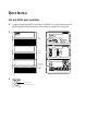
UPS and Battery Cabinet Storage
If you plan to store the UPS or battery cabinets prior to use, store them
in a cool, dry environment. Storage temperature should not exceed
35C (95F) in order to preserve battery life. For longer term storage,
energize the UPS and battery cabinet for approximately 8 hours every
90 days in order to maintain battery charge.
Whenever the units are not energized, verify the circuit breaker on all
battery cabinets is returned to the OFF (O) position.
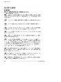
UPS with PowerPass Distribution Module Installation
The PPDM is a standard option for the AS/400 systems. The PPDM has a
Maintenance Bypass feature that supplies power to your equipment even
when the UPS electronics are removed for maintenance or upgrades.
There are three PPDM models available: the 5-15R PPDM, the
5-15R/6-15R PPDM, and the IEC 320-C13 PPDM. The rear panels of
these models are shown in Figure 5 on page 37, Figure 6 on page 38,
and Figure 8 on page 41, respectively.
Powerware® Prestige Series Installation and Operator’s Manual for IBM Applications (3000 VA) Uncontrolled Copy
35
Installation
Use the following procedure to install the UPS and battery cabinets with
the PPDM:
1. Place the UPS near the equipment to be protected. The UPS
should be well ventilated and away from direct sunlight or
other heat source.
Place the UPS and battery cabinets on top of or beside the
PPDM as shown in Figure 4.
NOTE You can install additional battery cabinets while the UPS is operating, but
confirm the UPS is not in Battery mode (see page 49).
UPS
Cabinet
Air Vents
Battery
Cabinet
PPDM
Battery
Cabinet
UPS
Cabinet
PPDM*
*NOTE: The IEC 320-C13 PPDM should
be placed on top of the UPS cabinet.
2.
3.
4.
5.
6.
36
Figure 4. Cabinet Setup
Verify the circuit breaker on all battery cabinets is in the
OFF (O) position.
Remove the battery connector guard. Plug the battery cord into
the external battery connector on the UPS. All battery
connectors are polarized to prevent incorrect connection.
If additional battery cabinets are to be used, plug the battery
cord of the second cabinet into the external battery connector
of the first battery cabinet. Follow this procedure for each
additional battery cabinet.
Remove the breaker tie from the circuit breaker on all battery
cabinets.
Switch the circuit breaker on all battery cabinets to the ON ( | )
position.
Powerware® Prestige Series Installation and Operator’s Manual for IBM Applications (3000 VA) Uncontrolled Copy
Installation
Serial Port
Power Input
Connector
Tie Wrap
Mounts
Battery
Connector
Input Circuit
Protector
Power Output
Receptacle
UPS Cabinet
REPO
Receptacle
(Optional)
Circuit
Breaker
External
Battery
Connector
Breaker Tie
Battery Cord
Battery
Cabinet
Bypass
Switch
Y-Cord
Load Circuit
Protectors
Utility Input
Connector
Power Output
Receptacles
(5-15R)
PPDM
Figure 5. UPS with 5-15R PPDM Rear Panel
Powerware® Prestige Series Installation and Operator’s Manual for IBM Applications (3000 VA) Uncontrolled Copy
37
Installation
Serial Port
Power Input
Connector
Tie Wrap
Mounts
Battery
Connector
Input Circuit
Protector
Power Output
Receptacle
UPS Cabinet
REPO
Receptacle
(Optional)
Circuit
Breaker
External
Battery
Connector
Breaker Tie
Battery Cord
Battery
Cabinet
Y-Cord
PPDM
Power Output
Receptacle
(IEC 320-C19)
Bypass
Switch
Output
Protectors
Neutral
Ground Screw
Power Output
Receptacles
(5-15R and
6-15R)
Utility Input
Connector
(IEC 320-C13)
Figure 6. UPS with 5-15R/6-15R PPDM Rear Panel
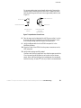
7. For 5-15R/6-15R PPDM Models Only: The factory default for the
PPDM output neutral is grounded. In some countries, the
output neutral should not be grounded. If your application
requires an ungrounded output neutral, continue with Step 7;
otherwise, skip to Step 8.
38
Powerware® Prestige Series Installation and Operator’s Manual for IBM Applications (3000 VA) Uncontrolled Copy
Installation
For ungrounded output neutral applications only. Remove the
ground screw, rotate the ground cover until it snaps into place,
and reinstall the ground screw in the ungrounded position (see
Figure 7).
Neutral Ground Screw
Ground Cover
Neutral Ground Screw
Grounded Position
(Default)
Ground Cover
Ungrounded Position
(For certain
applications only)
Figure 7. Output Neutral Ground Screw
8. Two tie wraps are included with the UPS to secure the Y-cord to
the input and output receptacles on the UPS rear panel. Insert
the tie wrap through the slot on each tie wrap mount.
9. Verify the Bypass switch on the PPDM rear panel is in the
NORMAL position.
10. Plug the Y-cord of the PPDM into the power connectors on the
UPS rear panel.
11. Verify that the plugs are fully seated.
If power cord locking is required: loop the tie wraps around the
Y-cord connections and tighten to secure the cord to the rear
panel. Allow sufficient slack in the cord between the receptacle
and the tie wrap. At least 122 (30 cm) of slack is recommended.
Powerware® Prestige Series Installation and Operator’s Manual for IBM Applications (3000 VA) Uncontrolled Copy
39
Installation
12. For the AS/400 interface, plug the AS/400 communications
cable into the serial port on the UPS rear panel. Plug the other
end of the cable into the J14 connector or the connector labeled
“UPS” on your AS/400.
Specific locations of the J14 serial port are listed below
according to the AS/400 model:
: AS/400 Models 3xx/5xx - located on the base power supply
on the back of the system unit
: AS/400 Models 600/S10/620/S20 - on the power supply
: AS/400 Models 640/S30/650/S40/SB1 - on the right side of the
regulator cage in the back of the tower
13. The equipment to be protected by the UPS should be powered
off. Plug the equipment into the power output receptacles on
the PPDM rear panel.
NOTES
: Use the IEC 320-C19/C20 output cord provided with the PPDM to connect the
AS/400 to the PPDM.
:
You may have to use the output cord provided with the PPDM for 230V usage.
:
The AS/400 line cord should be used from the PPDM input connector to the wall
outlet (see Step 4 on page 43). Some configurations require the input cord
provided with PPDM.
:
When using the PPDM, it is recommended that the equipment not be plugged
into the UPS cabinet.
:
Do not protect laser printers with the UPS/PPDM because of the exceptionally
high cyclic power requirements of the heating elements.
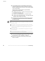
14. If you are using a Remote Emergency Power-Off switch, follow
the instructions in “REPO Installation” on page 44.
15. Start the UPS according to the following “UPS with PPDM
Startup” procedure.
40
Powerware® Prestige Series Installation and Operator’s Manual for IBM Applications (3000 VA) Uncontrolled Copy
Installation
PPDM
Bypass Switch
Utility Input
Connector
(IEC 320-C20)
Power Output
Receptacle
(IEC 320-C19)
Output
Breakers
Power Output
Receptacles
(IEC 320-C13)
Serial Port
Y-Cord
Power Input
Connector
Tie Wrap
Mounts
Battery
Connector
Input Circuit
Protector
Power Output
Receptacle
UPS Cabinet
REPO
Receptacle
(Optional)
Circuit
Breaker
External
Battery
Connector
Breaker Tie
Battery Cord
Battery
Cabinet
Figure 8. UPS with IEC 320-C13 PPDM Rear Panel
Powerware® Prestige Series Installation and Operator’s Manual for IBM Applications (3000 VA) Uncontrolled Copy
41
Installation
UPS with PPDM Startup
To start up the UPS:
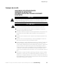
1. If you are connecting the UPS to an AS/400, the QUPSDLYTIM
system value for the UPS Monitoring feature should be set. See
“UPS Monitoring” on page 52 for instructions.
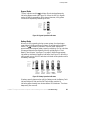
2. Confirm the Bypass switch on the PPDM rear panel is in the
NORMAL position.
3. Steps 4 through 8 are for changing the output voltage. The
output voltage is factory-configured for 230V. If you do not
need to change the output voltage, skip to Step 9.
Use the following table to select the correct output voltage
according to your PPDM.
PPDM Model Number
UPS Voltage Selection*
5-15R PPDM 208: 120/208
208
5-15R PPDM 208: 120/240
208
5-15R PPDM 208: 120
208
5-15R PPDM 240: 120/240
5-15R PPDM 240: 120
Set to 220V for 110/220V PPDM output
Set to 230V for 115/230V PPDM output
Set to 240V for 120/240V PPDM output
Set to 220V for 110V PPDM output
Set to 230V for 115V PPDM output
Set to 240V for 120V PPDM output
5-15R/6-15R PPDM: 208
208
5-15R/6-15R PPDM: 240
240
IEC 320-C13 PPDM
Set to 220V for 220V PPDM output
Set to 230V for 230V PPDM output
Set to 240V for 240V PPDM output
*The UPS output voltage should be set according to local mains voltage.
42
Powerware® Prestige Series Installation and Operator’s Manual for IBM Applications (3000 VA) Uncontrolled Copy
Installation
4. Plug the input power supply cord (use the AS/400 or PPDM
line cord) into the utility input connector on the PPDM rear
panel.
Off button while plugging the
Press and hold the Output
other end of the power supply cord into a grounded, three-wire,
AC receptacle that has been wired in accordance with NEC
specifications or national wiring rules. Release the
Off button when the alarm beeps. All indicators flash
Output
simultaneously.
5. Press and hold the Output On button until the alarm beeps
again.
Two indicators, corresponding with the current setting, remain
flashing. The output voltage is factory-configured for 230V.
OVERLOAD
SITE FAULT
OVERTEMP
BATTERY
SELF TEST
240V
230V
220V
208V
Figure 9. Output Voltage Indicators
6. Press the Output
Off button to scroll through the output
voltage options, top to bottom. Each time you press the button,
the UPS beeps and the next two indicators flash.
NOTE If you do not save a selection within two minutes, the setup automatically
aborts and switches back to the original configuration.
7. Press and hold the Output On button until the alarm beeps to
select and save the output voltage. Failure to release the button
immediately after the beep will cause the UPS to abort the
setup.
8. Continue to Step 10.
9. Plug the input power supply cord into the utility input
connector on the PPDM rear panel.
Plug the other end of the power supply cord into a grounded,
three-wire, AC receptacle that has been wired in accordance
with NEC specifications or national wiring rules.
Powerware® Prestige Series Installation and Operator’s Manual for IBM Applications (3000 VA) Uncontrolled Copy
43
Installation
10. Turn on the equipment that is connected to the UPS.
11. Press and hold the Output On button until you hear the UPS
beep (approximately one second).
The
indicator remains lit and the Self Test indicator turns
on. The front panel displays the percentage of full load being
applied to the UPS. The UPS is now in Normal mode with the
load online. See “Normal Mode” on page 48 for more
information.
REPO Installation
WARNING
Only qualified service personnel (such as a licensed electrician) should perform the
hardwired installation.
The REPO switch is a customer-supplied switch that can disconnect UPS
output voltage from your protected equipment. If you are using a REPO
switch, you need a junction box, external wiring, and a switch with the
following specifications:
: The switch should be a wall-mounted, momentary-contact, normally
open, pushbutton switch.
: Minimum ratings of 240 Vac and 35 mA.
: Wire should be 18 AWG (0.75 mm2) minimum.
CAUTION
44
:
The black and white REPO wires are at high-voltage potential (240V). Refer to your
local electrical code for proper installation of the high-voltage REPO wires.
:
To ensure the UPS stops supplying power to the load during any mode of
operation, the input power must be disconnected from the UPS when the
emergency power-off function is activated.
Powerware® Prestige Series Installation and Operator’s Manual for IBM Applications (3000 VA) Uncontrolled Copy
Installation
1. Place the conduit through the access hole on the junction box
(see Figure 10). Connect the exposed conduit wires to the
corresponding compression terminals (see the following table).
Tighten the compression terminals with a screwdriver.
2. Pivot the REPO receptacle guard out of the way, plug the REPO
plug/receptacle UPS connector into the REPO receptacle on the
UPS rear panel and twist the connector in place (see Figure 5
on page 37).
Mounting Holes
Plug/Receptacle
UPS Connector
Access Hole
for Conduit
Three Foot Cord
Terminal Block
Figure 10. Optional REPO Cord Junction Box
Power Cable Terminations
Wire Function
REPO
Terminal
Position
L1
TB1-4
L2
TB1-5
Ground
TB1-6
Terminal Wire
Size Rating*
12 - 22 AWG
(4 - 0 mm2)
Tightening Torque
Entrelec
Phoenix
Contact
3.5 - 5.3 lb in
5.6 - 6.8 lb in
*Suggested wire size is #18-AWG (0.75 mm2) 75C copper wire minimum.
NOTE The REPO function activates when L1 and L2 are shorted together.
Powerware® Prestige Series Installation and Operator’s Manual for IBM Applications (3000 VA) Uncontrolled Copy
45
Installation
Troubleshooting Tips
If you should encounter any problems during startup, see the
troubleshooting chart on page 71.
The battery cabinets are shipped with the batteries charged. However,
batteries may lose some of the charge during shipping and storage. You
can use the UPS immediately after unpacking, but it may not provide the
full-rated backup time during a power failure. Upon initial startup, the
UPS may need to operate for approximately 8 hours before the battery is
fully charged and full battery-backup time is available. If the Battery
Fault indicator flashes, operate the UPS for 24 hours to fully charge the
battery.
46
Powerware® Prestige Series Installation and Operator’s Manual for IBM Applications (3000 VA) Uncontrolled Copy
CHAPTER
4
UPS OPERATION
This chapter covers the operation of the UPS including front panel
functions, operating modes, using the Battery Start feature, shutting
down the UPS, and using the PowerPass Distribution Module.
UPS Front Panel
The UPS front panel has three distinct functions:
:
Displays the UPS operational mode (Normal, Bypass, or Battery).
:
Displays any alarm conditions present during operation (the
indicators flash).
:
Displays the loading percentage during Normal mode and the battery
capacity during Battery mode.
You can also use the front panel to configure UPS communication
options and to configure the UPS output voltage. See “Front Panel
Communications Access” on page 58 or “Changing the Output Voltage”
on page 51.
Output On Button
(UPS on, load online)
Output Off Button
(UPS off, load offline)
Sine Wave Indicator
Overload Indicator
Site Fault Indicator
Overtemp Indicator
Battery Fault Indicator
Self Test Indicator
Battery Online Indicator
Indicator Legend
Unlit
Amber
Green
Flashing
Figure 11. UPS Front Panel
Powerware® Prestige Series Installation and Operator’s Manual for IBM Applications (3000 VA) Uncontrolled Copy
47
UPS Operation
Operating Modes
After you install and apply power to the UPS, the UPS filters and
regulates incoming AC power, eliminating noise and voltage spikes, and
provides consistent power to your equipment (see Figure 12). While
power is applied to the UPS, the maintenance-free battery is
automatically kept in a fully-charged condition.
Bypass Line
Utility
Power
Surge
Suppression
EMI/RFI Filters
Inverter
Rectifier
UPS Load
Outlet
Battery Cabinets
Battery
Charger
Battery
Battery
Battery
Figure 12. UPS Block Diagram
Normal Mode
During Normal mode, the
indicator illuminates and the front panel
displays the percentage of UPS load capacity being used by the protected
equipment (see Figure 13).
OVERLOAD
SITE FAULT
OVERTEMP
BATTERY
SELF TEST
LOAD ON
APPROX.
81-100%
LOAD
LOAD ON
APPROX.
61-80%
LOAD
LOAD ON
APPROX.
41-60%
LOAD
LOAD ON
APPROX.
0-40%
LOAD
LOAD OFF
NORMAL
UTILITY
Figure 13. Normal Operation Indicators
48
Powerware® Prestige Series Installation and Operator’s Manual for IBM Applications (3000 VA) Uncontrolled Copy
UPS Operation
Bypass Mode
The
indicator and the
indicator illuminate simultaneously,
indicating Bypass mode (see Figure 14). When the UPS is in Bypass
mode, the load is powered by utility power. However, utility power
continues to be passively filtered by the UPS.
OVERLOAD
SITE FAULT
OVERTEMP
BATTERY
SELF TEST
LOAD ON
UNIT ON
BYPASS
Figure 14. Bypass Operation Indicators
Battery Mode
When the UPS is operating during a power outage, the alarm beeps
several times initially, and then once every 10 seconds while in Battery
indicator illuminates. The front panel displays the
mode. The
approximate percentage of battery capacity remaining. You can calculate
the approximate minutes of battery time by multiplying the “Total
Battery Time Minutes” (see Figure 3 on page 3) times the percentage
indicated by the Battery Operation indicators (see Figure 15). When the
utility power returns, the UPS switches to Normal mode operation while
the battery recharges.
OVERLOAD
SITE FAULT
OVERTEMP
BATTERY
SELF TEST
BATTERY
ONLINE
>75%
CAPACITY
REMAINS
BATTERY
ONLINE
>50%
CAPACITY
REMAINS
BATTERY
ONLINE
>25%
CAPACITY
REMAINS
BATTERY
ONLINE
LOW
BATTERY
WARNING
BATTERY
ONLINE
SHUTDOWN
IMMINENT
Figure 15. Battery Operation Indicators
If battery capacity becomes low while in Battery mode, the Battery Fault
indicator begins to flash and the Self Test indicator remains lit,
indicating approximately two minutes before UPS shutdown. The alarm
beeps every two seconds.
Powerware® Prestige Series Installation and Operator’s Manual for IBM Applications (3000 VA) Uncontrolled Copy
49
UPS Operation
When shutdown is imminent, the Self Test indicator flashes. These
warnings are approximate, and the actual time to shutdown may vary
significantly. For approximate battery times see the table on page 4.
Once these warnings are indicated, immediately complete and save your
work to prevent data loss and similar difficulties. When utility power is
restored after the UPS shuts down, the UPS automatically connects to
the load when the startup is complete.
Diagnostics
The UPS periodically performs diagnostic tests while the unit is
operating in Normal mode, ensuring proper operation. These tests
include:
:
Self Test
:
Utility Verification Test
:
Battery Discharge Test
:
Over Temperature Test
The UPS also runs a series of over 20 internal tests when power is first
applied. If a diagnostic test fails, see Chapter 7, “Troubleshooting” on
page 71.
Battery Test on Demand
You can perform a battery test on the UPS while it is operating in
Normal mode by pressing the Output On button. The UPS
automatically distributes some of the load to the batteries for 30 seconds
and tests the battery’s performance.
Battery Start
NOTE Before using this feature, the UPS must have been powered by utility power at
least once.
This feature allows you to start the UPS without utility power. After
utility power has been unavailable for one minute, press and hold the
Output On button until the alarm beeps.
50
Powerware® Prestige Series Installation and Operator’s Manual for IBM Applications (3000 VA) Uncontrolled Copy
UPS Operation
The UPS supplies power to your equipment and goes into Battery mode.
The
indicator remains lit and the front panel displays the percentage
of battery capacity remaining to the UPS. This process should take about
15 seconds.
UPS Shutdown
Performing a UPS shutdown turns off the power to your protected
equipment. Confirm the equipment is prepared for a power-off before
shutting down the UPS.
NOTE Do not perform a UPS shutdown if you want to use the Maintenance Bypass
feature on the PPDM (see “Using the PPDM” on page 53).
To perform a UPS shutdown:
1. Press and hold the Output
Off button until the long beep
ceases (approximately three seconds).
indicator remains lit indicating Normal mode, load
The
offline.
2. Unplug the UPS.
The UPS enters Battery mode for several seconds. The
indicator turns off and the UPS shuts down.
3. When all LEDs are no longer illuminated on the UPS, switch
the circuit breaker to the OFF (O) position on each battery
cabinet.
Changing the Output Voltage
To change the operating voltage of the UPS:
1. Perform a UPS shutdown as described in the previous section.
2. Follow the instructions in “UPS with PPDM Startup” on
page 42.
Powerware® Prestige Series Installation and Operator’s Manual for IBM Applications (3000 VA) Uncontrolled Copy
51
UPS Operation
UPS Monitoring
UPS monitoring is a standard feature of the AS/400 operating system.
QUPSDLYTIM is a timer in the AS/400 that tells the system how long to
run on UPS power before shutting down. Each AS/400 system is initially
assigned a default value for QUPSDLYTIM.
To determine the default value for your system or to change the value,
refer to the Uninterruptible Power Supply section in one of the
following IBM documents:
:
“AS/400 Advanced Series Backup and Recovery - Advanced,”
SC41-4305 (for AS/400 Models 3xx and 5xx)
:
“AS/400e series Backup and Recovery,” SC41-5304
(for AS/400 6xx and Sxx)
V4R1 Backup and Recovery information (AS/400 Models 3xx, 5xx, 6xx
and Sxx) is also available on the Customer Documentation AS/400
Softcopy Library CD (SK3T-0118) and on the Internet at:
http://publib.boulder.ibm.com.
NOTE *NOMAX tells the AS/400 to use customized shutdown software, and if none
is available it will begin shutdown immediately when utility power fails. Do not set
QUPSDLYTIM to “*NOMAX” unless you understand the implications of the “*NOMAX”
function as described in one of the IBM documents listed above.
52
Powerware® Prestige Series Installation and Operator’s Manual for IBM Applications (3000 VA) Uncontrolled Copy
UPS Operation
Using the PPDM
The PPDM provides continuous online power for your equipment. With
the PPDM, you can replace or upgrade the UPS without losing power to
your equipment. Figure 16 shows the operation of the UPS with the
PPDM.
Utility
Power
In
UPS
Out
UPS Load
PPDM
Battery
Battery
Battery
Figure 16. UPS and PPDM Block Diagram
Disconnecting the UPS
Use the following procedure to transfer the critical load to Maintenance
Bypass (AC Line operation) and remove the UPS:
1. Turn the Bypass switch on the PPDM to the BYPASS position
(see Figure 17). The PPDM is now powering your equipment
from utility power.
Off button until the long beep
2. Press and hold the Output
indicator
ceases (approximately three seconds). The
remains lit.
3. Remove the Y-cord connections from the UPS rear panel.
CAUTION
Do not remove the input power cord or your equipment from the PPDM.
Powerware® Prestige Series Installation and Operator’s Manual for IBM Applications (3000 VA) Uncontrolled Copy
53
UPS Operation
4. Switch the circuit breaker on all battery cabinets to the
OFF (O) position.
5. Disconnect the battery connector on the UPS rear panel.
6. Remove the UPS.
Power Input
Connector
Battery
Connector
Power Output
Receptacle
UPS Cabinet
Battery
Circuit
Breaker
Battery
Cabinet
Bypass
Switch
Y-Cord
PPDM
Figure 17. UPS with 5-15R PPDM Rear Panel
54
Powerware® Prestige Series Installation and Operator’s Manual for IBM Applications (3000 VA) Uncontrolled Copy
UPS Operation
Reconnecting the UPS
Use the following procedure to reinstall the UPS and transfer the critical
load from Maintenance Bypass (AC Line operation) to the UPS:
1. Reconnect the battery cabinet to the battery connector on the
UPS rear panel.
2. Switch the circuit breaker on all battery cabinets to the ON ( | )
position.
3. Steps 4 through 8 are for changing the output voltage. The
output voltage is factory-configured for 230V. If you do not
need to change the UPS output voltage, skip to Step 9. Use the
following table to select the correct output voltage according to
your PPDM.
PPDM Model Number
UPS Voltage Selection*
5-15R PPDM 208: 120/208
208
5-15R PPDM 208: 120/240
208
5-15R PPDM 208: 120
208
5-15R PPDM 240: 120/240
5-15R PPDM 240: 120
Set to 220V for 110/220V PPDM output
Set to 230V for 115/230V PPDM output
Set to 240V for 120/240V PPDM output
Set to 220V for 110V PPDM output
Set to 230V for 115V PPDM output
Set to 240V for 120V PPDM output
5-15R/6-15R PPDM: 208
208
5-15R/6-15R PPDM: 240
240
IEC 320-C13 PPDM
Set to 220V for 220V PPDM output
Set to 230V for 230V PPDM output
Set to 240V for 240V PPDM output
*The UPS output voltage should be set according to local mains voltage.
4. Press and hold the Output
Off button while plugging the
Y-cord of the PPDM into the power connectors on the UPS as
shown in Figure 17.
Release the Output
Off button when the alarm beeps.
All indicators flash simultaneously.
Powerware® Prestige Series Installation and Operator’s Manual for IBM Applications (3000 VA) Uncontrolled Copy
55
UPS Operation
5. Press and hold the Output On button until the alarm beeps
again.
Two indicators, corresponding with the current setting, remain
flashing. The output voltage is factory-configured for 230V.
OVERLOAD
SITE FAULT
OVERTEMP
BATTERY
SELF TEST
240V
230V
220V
208V
Figure 18. Output Voltage Indicators
6. Press the Output
Off button to scroll through the output
voltage options, top to bottom. Each time you press the button,
the UPS beeps and the next two indicators flash.
NOTE If you do not save a selection within two minutes, the setup automatically
aborts and switches back to the original configuration.
7. Press and hold the Output On button until the alarm beeps to
select and save the output voltage. Failure to release the button
immediately after the beep will cause the UPS to abort the
setup.
8. Continue to Step 10.
9. Plug the Y-cord of the PPDM into the power connectors on the
UPS as shown in Figure 17.
10. Press and hold the Output On button until you hear the UPS
beep (approximately one second).
The
indicator remains lit and the Self Test indicator
turns on.
11. Turn the Bypass switch on the PPDM to the NORMAL position.
The front panel displays the percentage of full load being
applied to the UPS. The UPS is now in Normal mode with the
load online.
56
Powerware® Prestige Series Installation and Operator’s Manual for IBM Applications (3000 VA) Uncontrolled Copy
CHAPTER
5
COMMUNICATION
The UPS is equipped with a communications interface port that allows
communication with a wide variety of external devices including:
:
Video or dumb terminal
:
Serial printer
:
Computer with power management or shutdown software
:
AS/400 systems
The serial port enables you to monitor and record diagnostic data with
the following communication interfaces:
:
Serial Communications Interface
Terminal Mode
Data Dump Mode
Printer Mode, 2400 Baud, with Novell Contacts (default)
Printer Mode, 19200 Baud, with Novell Contacts
:
LAN Configuration
9
Novell-Style
Network Interface
9
3Com-Style
Network Interface
9
AS/400-Style
Network Interface
Custom User-Configurable Interface
Initial Communications Settings
The UPS is factory-configured for one of several communication
interfaces (usually determined by the customer). To determine the initial
UPS communications configuration, you can:
:
Look at the box label with the serial number (communication mode
is shown in the upper right corner).
:
Use the Display Configuration option on the UPS Serial
Communications Menu (see page 60).
:
For assistance with IBM 9910 UPSs, see Chapter 8, “AS/400 Service”
on page 75.
If you want to change the UPS configuration settings, use the front panel
or the UPS Serial Communications Menu.
Powerware® Prestige Series Installation and Operator’s Manual for IBM Applications (3000 VA) Uncontrolled Copy
57
Communication
Front Panel Communications Access
Before you access the front panel, review the following configurations
and note the indicator that corresponds with the communication mode.
NOTE Only the Printer mode front panel options change the baud rate. Use the UPS
Serial Communications Menu to select other baud rates (see page 60).
Indicator Legend
Printer Mode, 2400 Baud, Novell Contacts
Select this mode for the OnliNet9 or LanSafe
Unlit
Amber
Green
Flashing
FRONT PANEL COMMUNICATION OPTIONS
software.
OVERLOAD
SITE FAULT
OVERTEMP
BATTERY
SELF TEST
Novell-Style LAN Contacts
3Com LAN Manager
Any baud rate other than 2400 or 19200
with Printer mode, or not Printer mode.
Any communication mode and baud rate
option.
OVERLOAD
SITE FAULT
OVERTEMP
BATTERY
SELF TEST
OVERLOAD
SITE FAULT
OVERTEMP
BATTERY
SELF TEST
AS/400-Style LAN Contacts, No Serial
Select this mode for the OnliSafe9 software.
OVERLOAD
SITE FAULT
OVERTEMP
BATTERY
SELF TEST
Printer Mode, 19200 Baud (network
devices), Novell Contacts
OVERLOAD
SITE FAULT
OVERTEMP
BATTERY
SELF TEST
Figure 19. Front Panel Communication Options
58
Powerware® Prestige Series Installation and Operator’s Manual for IBM Applications (3000 VA) Uncontrolled Copy
Communication
To access the front panel communication options, perform the following
steps:
1. If the UPS is powered on, prepare your equipment for
shutdown.
Off button until the long beep
Press and hold the Output
ceases (approximately three seconds).
Unplug the UPS. Wait until all indicators turn off and then
continue to the next step.
Off button until
2. Plug in the UPS while pressing the Output
the alarm beeps. All indicators begin flashing.
3. Press and hold the Output
alarm beeps again.
Off button a second time until the
A single indicator, corresponding with the current setting,
remains flashing.
4. Press the Output
Off button to scroll through the
communication options, top to bottom. Each time you press the
button, the UPS beeps and the next indicator flashes.
NOTE If you do not save a selection within two minutes, the setup automatically
aborts and switches back to the original configuration.
5. Press and hold the Output On button until the alarm beeps to
select and save a communication option. Failure to release the
button immediately after the beep will cause the UPS to abort
the setup.
6. Press the Output On button again to return the UPS to
Normal mode.
NOTE Printer mode selections are the only serial communication modes available
from the front panel.
Powerware® Prestige Series Installation and Operator’s Manual for IBM Applications (3000 VA) Uncontrolled Copy
59
Communication
UPS Serial Communications Menu
With the UPS Serial Communications (Main) Menu, you can view or
select UPS communication modes, baud rates, and LAN configurations.
To change or display the current communications configuration:
1. Connect the UPS serial port to a video monitor with a serial
interface or to your computer’s serial port. If you are using
OnliNet or LanSafe software, the UPS should already be
connected to your computer.
2. Set your terminal so that it matches the baud rate of the UPS
(usually 2400 baud, 8 bits, No parity, 1 stop bit). Refer to your
terminal or operating system documentation for details on
configuring your terminal communication settings.
3. At the terminal prompt, press Control-C until the UPS Serial
Communications Menu appears.
836 6(5,$/ &20081,&$7,216 0(18
6(/(&7 23(5$7,21 02'(
' !
',63/$< &21),*85$7,21
!
&217,18286 '803
32//(' '803
!
60$57 '803
!
$6&,, 7(50,1$/
$ !
97 7(50,1$/
% !
35,17(5 '803
3 !
/$1 &21),*85$7,21
/ !
6(7 %$8' 5$7(
= !
48,7 :,7+287 6$9,1* 1(: &21),*85$7,21
4 !
6$9( $1' 5(67$57
6 !
(17(5 6(/(&7,21 ! ! !
4. Select a menu option by typing the corresponding letter or
number key. All menu selections are single keystrokes and are
not case-sensitive.
D > Display Configuration displays the current communication
settings and the new settings that you have selected prior to
saving them. The new settings are not effective until you select
save from the Main Menu.
60
Powerware® Prestige Series Installation and Operator’s Manual for IBM Applications (3000 VA) Uncontrolled Copy
Communication
&DWDORJ 6HULDO 9HUVLRQ &200 PRGH
%DXG [
/$1 PRGH
6LWH )DXOW 'HWHFWLRQ
'&
%3&
6HUB3ULQW
1RYHOO
'LVDEOHG
1HZ &200
$6&,,
1HZ %DXG
1HZ /$1
1RYHOO
3UHVV VSDFH EDU WR FRQWLQXH
NOTE Catalog #, Serial #, and Version # are all identification numbers unique to your
UPS and can also be found on the UPS nameplate.
1 > Continuous Dump The UPS regularly transmits status
information to the computer. Baud rates of 1200 to 2400 are
recommended to reduce host computer overhead when using
this mode.
2 > Polled Dump Status information is transmitted only when
requested by a poll character (Control-E).
3 > Smart Dump Status information is transmitted when polled, as
in the previous mode. However, the transmission also occurs
automatically whenever UPS status changes. For example, if
there is a power outage, UPS status information changes and is
therefore, automatically transmitted.
A > ASCII Terminal The UPS displays the formatted data on the
attached video terminal.
B > VT100 Terminal The UPS displays the formatted data on the
attached video terminal.
P > Printer Dump The UPS prints the formatted data on the
attached printer.
L > LAN Configuration allows you to configure the UPS for a new
LAN mode and displays the Select LAN Configuration Menu.
Powerware® Prestige Series Installation and Operator’s Manual for IBM Applications (3000 VA) Uncontrolled Copy
61
Communication
6(/(&7 /$1 &21),*85$7,21
4
!
!
!
!
!
129(//
$6
&20/$1 0$1$*(5
&86720 &21),*85$7,21
72 48,7 7+,6 0(18
(17(5 6(/(&7,21 !!
Select the AS400 option if you are using OnliSafe software to
monitor the UPS.
The Custom Configuration option has two screens: the first screen
has options available for inverter shutdown, and the second
screen has options available for the contact configuration.
Consult your shutdown software documentation for details on
the required signal states for configuring LAN communications.
6(/(&7 &86720 /$1 &21),*85$7,21
,QVWUXFWLRQV &KRRVH WKH GHVLUHG LQYHUWHU VKXWGRZQ IXQFWLRQ
:DUQLQJ ,W LV UHFRPPHQGHG WKDW WKLV IHDWXUH VKRXOG QRW EH
XVHG ZLWK QRUPDO 56 FRPPXQLFDWLRQV FRQIOLFWV PD\ RFFXU
$
%
&
4
!
!
!
!
,QYHUWHU VKXWGRZQ FRQWURO LV HQDEOHG DFWLYH +,*+ 9
,QYHUWHU VKXWGRZQ FRQWURO LV HQDEOHG DFWLYH /2: 9
,QYHUWHU VKXWGRZQ FRQWURO LV GLVDEOHG
72 48,7 7+,6 0(18
(17(5 6(/(&7,21 ! !
6(/(&7 &86720 /$1 &21),*85$7,21
,QVWUXFWLRQV &KRRVH WKH GHVLUHG FRQWDFW FRQILJXUDWLRQ
4
!
!
!
!
!
87,/B)$,/ LV
87,/B)$,/ LV
87,/B)$,/ LV
87,/B)$,/ LV
72 48,7 7+,6
DFWLYH
DFWLYH
DFWLYH
DFWLYH
0(18
FORVHG /2:B%$77 LV DFWLYH FORVHG
RSHQ /2:B%$77 LV DFWLYH FORVHG
FORVHG /2:B%$77 LV DFWLYH RSHQ
RSHQ /2:B%$77 LV DFWLYH RSHQ
(17(5 6(/(&7,21 ! !
62
Powerware® Prestige Series Installation and Operator’s Manual for IBM Applications (3000 VA) Uncontrolled Copy
Communication
Z > Set Baud Rate allows you to select a new baud rate. The Select
Baud Rate Menu displays a list of baud rate options.
4
!
!
!
!
!
!
!
6(/(&7 %$8' 5$7(
48,7 7+,6 0(18
(17(5 6(/(&7,21 !!
5. To save the configuration settings, type S at the Main Menu
prompt. The UPS operates and communicates under the new
configuration, and defaults to these settings each time it is
started.
If you want to abandon the selections you have made, type Q to
quit.
NOTE Any changes you make to the UPS communications configuration must
correspond to the communications equipment you are using. In particular, new baud
rate selections for the UPS must match your communications equipment.
Power Management Software
Power management software allows you to monitor UPS operations
automatically. To use OnliNet or LanSafe software, the UPS must be
configured for any one of the Data Dump, Terminal, or Printer modes;
however, Printer mode is preferred.
OnliNet provides multiple levels of UPS monitoring and control, as well
as automatic shutdown for many different operating systems. If you
have any questions or would like further information, see Chapter 8,
“AS/400 Service” on page 75 for the number to call in your location.
Powerware® Prestige Series Installation and Operator’s Manual for IBM Applications (3000 VA) Uncontrolled Copy
63
Communication
UPS Communications Interface Port
In addition to configuring the UPS for specific communication options,
you must also ensure proper use of the serial port when connecting the
UPS to your network or monitoring equipment.
CAUTION
The serial port LAN contacts are transistors and are rated at a maximum current of
50 mA and a maximum of +40 Vdc. Do not exceed these ratings or apply any
negative voltage or AC voltage to these contacts; otherwise, damage may occur to
your UPS.
Use only the pins specified for your communications configuration. The
use of any additional pins for any of the following interfaces can cause
interference with system communications.
Even though your network uses the specified signal lines, the pins
assigned to these signals at the network end of the cable may vary with
those of the UPS serial port. The connector body and style may vary as
well.
NOTE Standard, pin-for-pin cables may not work correctly. Consult your network
software or server manuals for system shutdown pin assignments.
The UPS serial port complies with EIA RS-232 standards. RS-232
specifies a maximum cable length of 50 ft (15m). See Figure 20 for the
location of the serial port.
UPS Rear Panel
Serial
Port
Serial Port Detail
Figure 20. Serial Port Location
64
Powerware® Prestige Series Installation and Operator’s Manual for IBM Applications (3000 VA) Uncontrolled Copy
Communication
Communications Mode Reference Chart
The following chart defines the UPS serial port contacts. Serial
communication is not available with 3Com and AS/400 network
configurations. Use only the applicable pins for the selected
communication mode; otherwise, interference problems may occur.
Communication Mode Function
Signal Name Pin No.
True Condition
Serial
Data to UPS
RS232 TxD
2
N/A
Data from UPS
RS232 RxD
3
N/A
Signal Ground
Novell
(D f l )
(Default)
7
Battery On
ON.AC
14/16
Open
Low Battery
TWO.MIN
23/24
Closed
Signal Ground
Novell
(C
(Custom)
)
3Com
(D f l )
(Default)
7/15/25
Battery On
ON.AC
14/16
Closed
Low Battery
TWO.MIN
23/24
Closed
Signal Ground
7/15/25
Shutdown (Remote) SHUT.DOWN
2
Positive Voltage
Low Battery
LOW.BATT
9
Positive Voltage
Battery On
PWR.FAIL
10
Positive Voltage
Signal Ground
AS/400
7
UPS Available
UPS Available
11/13
Closed
Battery On
Utility Failure
14/16
Closed
Bypass
UPS Offline
17/19
Closed
Low Battery
Low Battery
23/24
Closed
Signal Ground
12/15/18/25
NOTE Pin numbers separated by a forward slash ( / ) are connected together internally.
Powerware® Prestige Series Installation and Operator’s Manual for IBM Applications (3000 VA) Uncontrolled Copy
65
Communication
This page intentionally left blank.
66
Powerware® Prestige Series Installation and Operator’s Manual for IBM Applications (3000 VA) Uncontrolled Copy
CHAPTER
6
SPECIFICATIONS
3000 VA Model Specification with PPDM
Input
Current
Output Current
(Total not to exceed 2000 Watts, 3000 VA)
208:120/208
13.0A
12.50A/14.40A
208:120/240
13.0A
12.50A
240:120/240
11.3A
12.50A
208:120
13.0A
12.50A (2x5-15R)/25.00A (L5-30R)
240:120
11.3A
12.50A (2x5-15R)/25.00A (L5-30R)
220:220
12.3A
13.64A
230:230
11.7A
13.04A
240:240
11.3A
12.50A
Voltage In:Out
Prestige 3000 UPS Physical Specifications
Parameter
UPS Cabinet
Battery Cabinet
PowerPass Distribution Module
Height
252 mm (9.91”)
252 mm (9.91”)
252 mm (9.91”)
Width
142.5 mm (5.61”)
142.5 mm (5.61”)
142.5 mm (5.61”)
Depth
400 mm (15.75”)
400 mm (15.75”)
400 mm (15.75”)
Weight
7.4 kg (16.25 lb)
23.6 kg (52 lb)
21.4 kg (47 lb)
Powerware® Prestige Series Installation and Operator’s Manual for IBM Applications (3000 VA) Uncontrolled Copy
67
Specifications
Prestige 3000 UPS Technical Specifications
Input Voltage Range
160 to 276 Vac
Input Power Factor
0.95 Typical
Frequency Range
50/60 Hz ±3 Hz
Surge Protection
IEC 801-4
Output Waveform
Sine wave
Output Voltage
(without PPDM)
200/208/220/230/240 Vac ±3%
Online (BTUs)
978
On Battery (BTUs)
1468
Common Mode Noise
Rejection
>60 dB @ 100 kHz
Transverse Mode Noise
Rejection
>80 dB @ 100 kHz
Input Cord
Detachable 2-meter cord
Outlets (UPS Cabinet)
Output Voltages and Outlets
(with PPDM)
Batteries (10) per cabinet
Battery Cabinet
IEC 320 (1)
120/208V: 5-15R (2), 6-15R (2), IEC 320-C19 (1)
120/240V: 5-15R (2), 6-15R (2), IEC 320-C19 (1)
220/230/240V: IEC 320-C13 (6), IEC 320-C19 (1)
120/208V: L6-30R (1), 5-15R (4)
120/240V: L6-30R (1), 5-15R (4)
12 Vdc, 5 Ah, maintenance-free rechargeable lead acid
120 Vdc
Operating Environment
Temperature: 10C to 40C
(50F to 104F)
Humidity:
5 to 95%
(noncondensing)
Agency Approvals
Safety: EN50091-1
UL 1778
cUL
EMC: FCC Part 15 Class A
EN50091-2
68
Powerware® Prestige Series Installation and Operator’s Manual for IBM Applications (3000 VA) Uncontrolled Copy
Specifications
Part Numbers
Base Equipment
Machine
Type
Model
IBM Part
Number
VA
Watts
Volts
Frequency
Description
9910
EP5
21H1572
3000
2100
120/208 or 120/240
50-60
Prestige 3000 Model 3000
All models include electronics module, PPDM (208V or 240V) input line cord, AS/400 communications cable, operator’s
manual, and one battery pack.
Standard Accessories
IBM Part Number
IBM Type/Model
Description
N/A
9910-6602
Prestige 3000 Full Battery Pack
17G1792
9910-6561
Prestige 3000 PowerPass Distribution Module
(IEC 320-C13 PPDM: 120/208)
17G1793
9910-6562
Prestige 3000 PowerPass Distribution Module
(5-15R/6-15R PPDM: 120/208)
17G1794
9910-6563
Prestige 3000 PowerPass Distribution Module
(5-15R/6-15R PPDM: 120/240)
21H8436
9910-6550
Prestige 3000 PowerPass Distribution Module
(5-15R PPDM: 120/208)
21H8437
9910-6551
Prestige 3000 PowerPass Distribution Module
(5-15R PPDM: 120/240)
IBM Part Number
Powerware Part Number
Description
17G2374
124102011-001
15-ft. AS/400 Communications Cable
N/A
152507429-003
L6-30P Input Line Cord
N/A
152507829-001
IEC 320-C19/IEC 309 Input Line Cord
(for 9910-6561 only)
N/A
152507429-014
IEC 320-C19/L6-30P Input Line Cord
(for 9910-6562 and 9910-6563)
N/A
152507429-017
IEC 320-C19/C20 Output Cord
(for 9910-6561, 9910-6562, and 9910-6563)
N/A
152600403-001
IEC 320-C13/C14 Output Cord (Qty. 4)
(for 9910-6561 only)
N/A
152507379-001
IEC 320-C13/5-15P Output Cord
(for 9910-6562 and 9910-6563)
N/A
152600358-001
IEC 320-C13/6-15P Output Cord (Qty. 2)
(for 9910-6562 and 9910-6563)
Powerware® Prestige Series Installation and Operator’s Manual for IBM Applications (3000 VA) Uncontrolled Copy
69
Specifications
Optional Accessories
IBM Part Number
IBM Type/Model
Description
21H8444
9910-6602
Prestige 3000 Full Battery Pack
Manuals
IBM Order
Number
SC21-8379
Description
Powerware Prestige Series Installation and Operator’s Manual for IBM Applications (3000 VA)
Manuals may be ordered from the IBM Mechanicsburg Distribution Center.
70
Powerware® Prestige Series Installation and Operator’s Manual for IBM Applications (3000 VA) Uncontrolled Copy
CHAPTER
7
TROUBLESHOOTING
The Prestige UPS is designed for durable, automatic operation and also
alerts you whenever potential operating problems may occur. Use the
following troubleshooting chart to determine the UPS alarm condition.
Indicator Legend
Unlit
Amber
Green
Flashing
Condition
Possible Cause
Action
UPS does not turn on.
UPS is not plugged in.
Plug UPS into working outlet.
Faulty wall socket.
Test wall socket, repair as required.
UPS input breaker is tripped.
Reduce load, then reset breaker.
Load does not turn on.
UPS has not been activated.
Press the Output | On button for one
second, then release.
UPS beeps occasionally.
Normal operation.
None. UPS is protecting your
equipment.
UPS input breaker trips.
Load fault.
Check the load.
Disconnect faulty load equipment.
Wait several minutes before resetting
the UPS input breaker.
Restart the load.
indicator remains
lit,, even though
g line
voltage
l
is present.
Utility line is out of
specification.
Test wall socket, repair as required.
UPS input breaker is tripped.
Reduce load, then reset breaker.
Low battery capacity.
Allow battery to charge for 24 hours,
then retest.
Protected equipment power
requirements exceed UPS
capacity.
Reduce load, then retest.
UPS does not provide
the expected backup
ti
time.
Powerware® Prestige Series Installation and Operator’s Manual for IBM Applications (3000 VA) Uncontrolled Copy
71
Troubleshooting
Condition
Possible Cause
Action
Communications do not
function properly.
Incorrect communications
cabling.
Verify cable integrity (see page 64).
Incorrect baud rate.
Select a new baud rate (see page 63).
Incorrect communication mode.
Select a new communication mode
(see Chapter 5).
Load plug(s) not fully seated.
Verify load plug(s) are fully seated.
Load circuit protectors tripped.
Reset load protectors.
Power requirements exceed UPS
capacity. If overload is greater
than 105%, the alarm beeps
every second and the UPS may
switch to Bypass mode.
Your UPS continues to operate.
Reduce load.
The UPS switched to Bypass
mode because the overload
increased (above 105%). The
alarm beeps.
Reduce load.
If the Overload indicator remains lit,
reset the UPS by pressing the
Output | On button until the alarm
beeps.
You may need to obtain a larger
capacity UPS.
The utility line voltage and
frequency are out of
specification.
The inverter remains online, deriving
power from the utility until it is no
longer acceptable.
Check the unit configuration.
Refer to the product specifications
(see page 67).
UPS internal temperature is too
high. The alarm beeps and the
UPS switches to Bypass mode for
approximately 10 minutes,
allowing the UPS to cool down.
Shut down the UPS. Clear vents.
Remove any heat sources. Wait
approximately 5 minutes and retry.
Contact your service representative if
condition persists.
Weak battery while in Normal
mode. The alarm beeps.
Allow the battery to charge for
24 hours, then retest. Have batteries
replaced if condition persists.
Battery breaker is open (O).
Verify that the battery cabinet breaker
is in the ON ( | ) position.
Battery cabinet is not properly
connected to the UPS.
Verify that the battery cords are
connected.
No output load voltage.
OVERLOAD
SITE FAULT
OVERTEMP
BATTERY
SELF TEST
OVERLOAD
OVERTEMP
BATTERY
72
Powerware® Prestige Series Installation and Operator’s Manual for IBM Applications (3000 VA) Uncontrolled Copy
Troubleshooting
Condition
Possible Cause
Action
Weak battery while in Bypass
mode.
This usually indicates that the
batteries need replacing or the UPS
requires service. Contact your service
representative.
Self Test failure. UPS internal
problem.
The UPS may switch to Bypass mode,
depending on the circumstances.
Reset the UPS by pressing the
Output | On button until the alarm
beeps.
Contact your service representative if
condition persists.
BATTERY
SELF TEST
Resetting the UPS
To reset the UPS while an alarm condition is present, press the
Output On button until the UPS alarm beeps.
Silencing the Alarm
To silence the alarm for an existing fault, press and hold the
Output On button for one second. The alarm becomes quiet.
If UPS status changes, the alarm beeps, overriding previous alarm
silencing. Press the Output On button again to silence the alarm.
Powerware® Prestige Series Installation and Operator’s Manual for IBM Applications (3000 VA) Uncontrolled Copy
73
Troubleshooting
This page intentionally left blank.
74
Powerware® Prestige Series Installation and Operator’s Manual for IBM Applications (3000 VA) Uncontrolled Copy
CHAPTER
8
AS/400 SERVICE
The following sections describe the methods for obtaining service for
your UPS and warranty information.
Warranty
The warranty service on Powerware UPSs is element exchange. If the
UPS becomes inoperative, the module that is inoperative will be
replaced. For 3 kVA UPSs, this would either be the I/O, battery, or
PowerPass Distribution Module. The process for obtaining a
replacement module varies by country. Under NO CONDITIONS are
IBM Customer Engineers authorized to remove the covers.
The warranty on the replacement unit, should you require one, is for the
remaining period of warranty of the original unit. See page 79 for a
detailed description of the warranty.
Installation Instructions
Installation instructions are in pictorial form on the Quick Install pages
in the front of this manual and also in written form beginning on page
35. Safety instructions are provided in multiple languages and begin on
page 7. Publications may be ordered from the IBM Mechanicsburg
Distribution Center.
Connected Equipment Insurance
With this program, Powerware Corporation provides a $25,000
Powerware Protection Guarantee. See page 80 for specific terms and
conditions of the Powerware Protection Guarantee.
Powerware® Prestige Series Installation and Operator’s Manual for IBM Applications (3000 VA) Uncontrolled Copy
75
AS/400 Service
Battery Warranty
If, in Powerware Corporation’s opinion, the unit fails to meet published
specifications and the defect is within the terms of the limited warranty
(attached), the defective part(s) will be repaired or replaced at the
option of Seller with no charge for replacement parts. The battery is
warranted to have at least 70% of original full load capacity at the end of
five years from date of installation or 66 months after manufacture,
whichever comes first. The warranty is invalid if the battery is subject to
misuse, abuse, or physical damage.
Warranty
Model
Part Number
EP5
21H1572
Coverage Area
5 Year
AP, Canada, LA, US
X
EMEA
3 Year
X
Obtaining Service
The troubleshooting chart on page 71 covers most of the difficulties you
may encounter during normal operations.
For further assistance with IBM 9910 UPSs, see the following section
that applies to you. For critical applications, expedited replacement may
be available.
Please have the following information ready when you call for service:
76
:
Model number
:
Serial number
:
Version number (if available)
:
Date of failure or problem
:
Symptoms of failure or problem
:
Customer return address and contact information
Powerware® Prestige Series Installation and Operator’s Manual for IBM Applications (3000 VA) Uncontrolled Copy
AS/400 Service
Customer Responsibilities
The customer is responsible for the following element exchange items:
:
Receiving, unpacking, and exchanging of the defective element.
:
Repacking the defective element in the container received with the
replacement element.
:
Following the instructions provided for return of the defective
element.
IBM on-site service for the element exchange activities is available for an
additional charge.
United States
Customer Process for Service
1. Customer calls 1-800-IBMSERV (Field Services Support-FSS).
2. Customer indicates that the UPS is defective.
3. The FSS will confirm that the unit is listed in the customer
profile and notify Powerware.
4. Powerware will promptly call the customer and ask for the
serial number. Powerware will also attempt to determine the
nature of the problem. The problem may be related to improper
operation as opposed to a defect.
5. If the unit requires replacement, Powerware will send a
replacement unit.
6. The customer is expected to install the replacement unit. To
return the defective unit see the instructions on the bottom of
the Return Material Authorization (RMA). The packaging
material used for the replacement unit can be used for this
purpose.
Shipping
Powerware will pay all shipping costs incurred (both to and from the
customer site or IBM Designated Location) to replace the defective UPS
system.
Powerware® Prestige Series Installation and Operator’s Manual for IBM Applications (3000 VA) Uncontrolled Copy
77
AS/400 Service
Handling of Incomplete, Damaged, or Incorrectly Shipped 9910
UPSs
If the customer initially receives a 9910 UPS that is incomplete,
damaged, or incorrectly shipped:
1. The customer calls IBM at 1-800-IBMSERV to report the
problem.
2. An IBM representative notifies the customer of how the
problem will be resolved.
Canada
Customer Process for Service
1. Customer calls 1-800-426-7378.
2. Dispatch takes the information from the customer and notifies
the IBM Customer Service Representative (CSR).
3. Problem determination is performed by the CSR.
4. If a replacement unit is required, the unit is ordered out of
stock and sent to the customer.
5. The CSR does the swap and returns the defective unit to the
IBM parts center.
Latin America
Customer Process for Service
1. Customer calls the local IBM office servicing account.
2. The IBM CE responds, determines the problem, and resolves
the problem.
Asia Pacific
Customer Process for Service
1. Customer calls the local IBM office servicing account.
2. The IBM CE responds, determines the problem, and resolves
the problem.
78
Powerware® Prestige Series Installation and Operator’s Manual for IBM Applications (3000 VA) Uncontrolled Copy
AS/400 Service
EMEA
Customer Process for Service
1. Customer calls the local IBM office servicing account.
2. The IBM CE responds, determines the problem, and resolves
the problem.
IBM Powercare9 Five-Year Warranty
Applies only to electronics (unit) installed in the 50 United States of America, Canada, Latin America, and Asia Pacific:
Powerware Corporation warrants the unit against defects in material and workmanship for a period of five years from the
date of startup or sixty-six (66) months from the date of completion of manufacture, whichever period expires first.
If, in Powerware Corporation’s opinion, the unit fails to meet published specifications and the defect is within the terms of
this limited warranty, the defective part(s) will be repaired or replaced at the option of Seller with no charge for
replacement parts. There will be no charge for replacement equipment installation or defective part repair in connection
with defects covered by this Limited Warranty. Equipment sold, but not manufactured, by Seller (e.g. batteries, battery
racks), shall be warranted only by the manufacturer of such equipment, Prestige 3000 Powerware Corporation’s line up
and match batteries are warranted for 5 years from start-up or 66 months from manufacture subject to the terms attached
hereto. Equipment repaired or replaced pursuant to this Limited Warranty will be warranted for the unexpired portion of
the original warranty subject to all the terms thereof.
This warranty does not apply to any unit that has been subject to neglect, accident, abuse, misuse, misapplication,
incorrect connection, or that has been subject to repair or alteration not authorized in writing by Powerware Corporation
personnel. THIS WARRANTY IS THE PURCHASER’S (USER’S) SOLE REMEDY AND IS EXPRESSLY IN LIEU OF ANY
OTHER WARRANTY, AND THERE ARE NO OTHER EXPRESSED OR IMPLIED GUARANTEES OR WARRANTIES
INCLUDING ANY IMPLIED WARRANTY OF MERCHANTABILITY OF FITNESS FOR PURPOSE. Powerware
Corporation’s liability on any claim of any kind relating to the unit, batteries or otherwise for any loss or damage arising
out of or in connection with or resulting from this Agreement or from the performance or breach thereof shall in no case
exceed the price allocable to the goods or services or unit thereof which gives rise to the claim.
Seller’s obligations under this Limited Warranty are conditioned upon receipt by Seller of all payments due (including
interest charges, if any). During such time as Seller has not received payment of any amount due to Seller in accordance
with the Contract terms under which the equipment is sold, Seller shall have no obligation under said warranty; also
during this time the period of said warranty shall continue to run and the expiration of said warranty shall not be
extended upon payment of the overdue amount. These limitations to said warranty apply even in the event that the
equipment is sold by Seller for resale to an ultimate user.
In no event shall Seller be liable for any indirect, incidental, special, or consequential damages. Seller shall not be
responsible for failure to provide service or parts due to causes beyond Seller’s reasonable control.
Any advice furnished the Purchaser (user) before or after delivery in regard to use or application of Powerware
Corporation equipment, is furnished without charge and on the basis that it represents Powerware Corporation’s best
judgment under the circumstances. The use of any verbal advice by the Purchaser (user) is solely and entirely at its own
risk.
Preventive Maintenance (PM) is not required on the product to maintain the warranty.
This limited warranty applicable only to products purchased from the IBM Corporation.
Powerware® Prestige Series Installation and Operator’s Manual for IBM Applications (3000 VA) Uncontrolled Copy
79
AS/400 Service
Powerware Protection Guarantee
Attached Equipment Protection Program Terms and Conditions
Program Summary: Powerware Corporation guarantees to repair or replace (at the option of Powerware Corporation)
any equipment that is damaged by AC power disturbances when said equipment is properly connected to a Powerware
Corporation uninterruptible power supply (UPS) covered by the Powerware Protection Guarantee. This program provides
for reimbursement of repair or replacement expenses up to $25,000.00 and applies only to component or physical system
damage.
Products Covered: The Powerware Protection Guarantee applies to all Powerware Corporation Prestige 3000 UPS
systems that are covered under the original IBM AS/400 Powercare Limited warranty during the manufacturer’s warranty
period.
Applicability: The Powerware Protection Guarantee applies only to units installed in the United States of America, Latin
America, Canada, Asia Pacific and were sold by IBM Corporation with AS/400 systems. Further, this Powerware
Protection Guarantee applies only to end-users of the UPS product(s) who have returned the warranty registration card
within 30-days after product delivery. This program does not apply to damage resulting from any cause other than AC
power disturbances and is independent of the Powerware Corporation manufacturer’s warranty or service contract. The
Powerware Protection Guarantee applies to the following AC power disturbances as defined by the American National
Standards Institute (ANSI): power line transients; electrical spikes; electrical surges; brownout; blackout. UPS products
must be properly maintained according to the manufacturers’ recommendations set forth in the operator’s manual and the
UPS installation must adhere to electrical safety requirements set forth by the National Electrical Code (NEC) or
applicable local code(s). The UPS must be properly connected to a properly installed electrical outlet or other connection
per the NEC or applicable local code (s). The equipment covered by this guarantee must be connected directly to the
output of the Powerware Corporation UPS product with no intervening electrical devices. The Powerware Protection
Guarantee is null and void if the UPS product has been: misapplied; improperly maintained; mishandled; abused;
improperly installed; altered in any way subjected to accident or misuse; used in other than normal operating conditions
described in the UPS product specifications. The Powerware Protection Guarantee is independent of all other warranties
and there are no other warranties expressed or implied, including warranties of merchantability and fitness for a particular
purpose. IN NO EVENT SHALL POWERWARE CORPORATION BE LIABLE FOR ANY DIRECT, INDIRECT, SPECIAL,
INCIDENTAL OR CONSEQUENTIAL DAMAGES ARISING OUT OF THE USE OF ITS’ PRODUCTS, EVEN IF ADVISED
OF THE POSSIBILITY OF SUCH DAMAGE. Direct, indirect, special, incidental or consequential damages include, but are
not limited to, lost profits or revenue, loss of equipment, loss of use of equipment, software loss, loss of data in whole or
in part, recovery of data in whole or in part, restoration of data in whole or in part, corruption of data in whole or in part,
cost of substitutes or rental equipment, claims by third parties or otherwise.
80
Powerware® Prestige Series Installation and Operator’s Manual for IBM Applications (3000 VA) Uncontrolled Copy
INDEX
Numeric
3Com Network Interface
front panel configuration, 58
LAN Configuration Menu, 62
A
Battery Fault
alarm, 72
indicator, 47
Battery Mode, 49
Battery Online, indicator, 47
Battery Start, 50
Battery Test on Demand, 50
AC Line
Bypass switch, 53
operation, 53
alarm
silencing, 73
UPS, 72
baud rates, 60, 63
Bypass Mode, 49
Bypass switch, 37, 38, 41
C
changing the output voltage, 51
Alarm Conditions
Battery Fault, 72
Overload, 72
Overtemperature, 72
Self Test Failure, 73
Utility Out of Spec, 72
communication
interface port, 64
modes, 60
UPS, 57
AS/400 Network Interface
front panel configuration, 58
LAN Configuration Menu, 62
configuration settings
abandoning, 63
displaying, 60
front panel, 58
saving, 63
ASCII Terminal Mode, 61
B
battery
circuit breaker, 37, 38, 41
configuration, 2
extension time, 3
input connector, 37, 38, 41
installation, 35
output connector, 37, 38, 41
storage, 35
Communications Mode Reference
Chart, 65
contact configuration, serial port, 64
Continuous Dump Mode, 61
Control Keys
Control-C, 60
Control-E, 61
cord, power, 43, 68
Custom LAN Configuration
Menu, 62
customer service, 75
Powerware® Prestige Series Installation and Operator’s Manual for IBM Applications (3000 VA) Uncontrolled Copy
81
Index
D
Data Dump Modes, 61
diagnostics, 50
Display Configuration Screen, 61
load
definition, 2
requirements, 2
LOW_BATT, 62
M
Main Menu, 60
E
exiting Main Menu, 63
F
front panel
configuring communications, 58
display functions, 47
indicators, 47
front panel configuration
3Com, 58
AS/400, 58
Novell, 58
printer mode, 58
I
indicators, front panel, 47
input cord, 43, 68
82
Maintenance Bypass feature
See also PowerPass Distribution
Module (PPDM)
activating, 53
deactivating, 55
Menu
Custom LAN Configuration, 62
LAN Configuration, 62
Main, 60
Serial Communications, 60
Set Baud Rate, 63
Mode
ASCII Terminal, 61
Battery, 49
Bypass, 49
Communications, 60
Data Dump, 61
Normal, 48
Printer, 59, 61
Terminal, 61
VT100 Terminal, 61
Inverter Shutdown Control, 62
N
L
Normal Mode
indicator, 47
operation, 48
LAN Configuration
Main Menu option, 60
menu, 62
Novell Network Interface
front panel configuration, 58
LAN Configuration Menu, 62
Powerware® Prestige Series Installation and Operator’s Manual for IBM Applications (3000 VA) Uncontrolled Copy
Index
O
Operating Modes, 48
Operation
Battery, 49
Bypass, 49
Normal, 48
UPS with PPDM, 53
Output Off Button, 5, 47
Maintenance Bypass feature, 35
operation, 53
power output
receptacles, 37, 38, 41
rear panel, 37, 38, 41
startup, 42
utility input connector, 37, 38, 41
Printer Mode
front panel configuration, 59
Main Menu configuration, 61
Output On Button, 5, 47
output voltage
changing, 51
initial setting, 42
R
Remote Emergency Power-Off
switch. See REPO switch
Overload
condition, 72
indicator, 47
REPO switch, plug/receptacle
UPS, 44
Overtemperature
alarm, 72
indicator, 47
S
P
plug/receptacle UPS, installation
optional REPO cord junction
box, 45
REPO switch, 44
Polled Dump Mode, 61
Power Management Software
LanSafe, 58, 63
OnliNet, 58, 63
OnliSafe, 58, 62
PowerPass Distribution Module
(PPDM)
AC Line operation, 53
block diagram, 53
installation, 35
resetting the UPS, 73
Safety Warnings, 7
Self Test
failure, 73
indicator, 47
serial cable, 64
serial port
contact ratings, 64
description, 64
service
for incomplete, damaged, or
incorrect UPS, 78
in Asia Pacific, 78
in Canada, 78
in EMEA, 79
in Latin America, 78
in the US, 77
obtaining, 76
Powerware® Prestige Series Installation and Operator’s Manual for IBM Applications (3000 VA) Uncontrolled Copy
83
Index
Service and Support, 75
Set Baud Rate Menu, 63
shutdown, 51
Site Fault, indicator, 47
Smart Dump Mode, 61
specifications, 67
Startup Tests, 50
storage temperature, 35
Switch, Bypass, 37, 38, 41
system requirements, 2
T
Terminal Modes, 61
Tests
Battery (on demand), 50
Startup, 50
transistors, contact ratings, 64
troubleshooting
chart, 71
tips, 46
U
front panel, 47
input circuit protector, 37, 38, 41
installation, 35
operation, 47
operation with PPDM, 53
power input connector, 37, 38, 41
power output receptacle, 37, 38, 41
rear panel, 37, 38, 41
resetting, 73
Serial Communications Menu, 60
serial port, 37, 38, 41, 64
shutdown, 51
special symbols, 5
storage, 35
unpacking and inspection, 35
UTIL_FAIL, 62
Utility Out of Spec, 72
V
volt-amperes, 2
uninterruptible power system, 1
UPS
alarm silencing, 73
alarms, 72
block diagram, 48
changing output voltage, 51
communication, 57
Communications Mode Reference
Chart, 65
external battery
connector, 37, 38, 41
84
VT100 Terminal Mode, 61
W
warranty
battery, 76
IBM five-year, 79
Powerware® Prestige Series Installation and Operator’s Manual for IBM Applications (3000 VA) Uncontrolled Copy
Powerware® Prestige Series Installation and Operator’s Manual for IBM Applications (3000 VA) Uncontrolled Copy
85
164201134 C
86
Powerware® Prestige Series Installation and Operator’s Manual for IBM Applications (3000 VA) Uncontrolled Copy