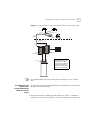
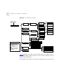
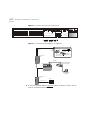
1
Visitor and Community
Network Access
Concentrator
SERVICE MANUAL
Release 2.0
http://www.3com.com/
Part No. DSA-3CV1100-02
Published August 2000
3Com Corporation
5400 Bayfront Plaza
Santa Clara, California
95052-8145
Copyright © 2000, 3Com Corporation. All rights reserved. No part of this documentation may be reproduced
in any form or by any means or used to make any derivative work (such as translation, transformation, or
adaptation) without written permission from 3Com Corporation.
3Com Corporation reserves the right to revise this documentation and to make changes in content from time
to time without obligation on the part of 3Com Corporation to provide notification of such revision or change.
3Com Corporation provides this documentation without warranty, term, or condition of any kind, either
implied or expressed, including, but not limited to, the implied warranties, terms or conditions of
merchantability, satisfactory quality, and fitness for a particular purpose. 3Com may make improvements or
changes in the product(s) and/or the program(s) described in this documentation at any time.
If there is any software on removable media described in this documentation, it is furnished under a license
agreement included with the product as a separate document, in the hard copy documentation, or on the
removable media in a directory file named LICENSE.TXT or !LICENSE.TXT. If you are unable to locate a copy,
please contact 3Com and a copy will be provided to you.
UNITED STATES GOVERNMENT LEGEND
If you are a United States government agency, then this documentation and the software described herein are
provided to you subject to the following:
All technical data and computer software are commercial in nature and developed solely at private expense.
Software is delivered as “Commercial Computer Software” as defined in DFARS 252.227-7014 (June 1995) or
as a “commercial item” as defined in FAR 2.101(a) and as such is provided with only such rights as are
provided in 3Com’s standard commercial license for the Software. Technical data is provided with limited rights
only as provided in DFAR 252.227-7015 (Nov 1995) or FAR 52.227-14 (June 1987), whichever is applicable.
You agree not to remove or deface any portion of any legend provided on any licensed program or
documentation contained in, or delivered to you in conjunction with, this User Guide.
Unless otherwise indicated, 3Com registered trademarks are registered in the United States and may or may not
be registered in other countries.
3Com, the 3Com logo, and SuperStack, are registered trademarks of 3Com Corporation. 3Com Facts is a
service mark of 3Com Corporation.
Procomm Plus is a registered trademark of Datastorm Technologies, inc., a subsidiary of Quarterdeck
corporation. All other company and product names may be trademarks of the respective companies with
which they are associated.
Guide written by Ruth Zach and Ronald Schwarz. Illustrated by Pearl Goldberg and Ronald Schwarz. Produced
by 3Com Corporation.
CONTENTS
ABOUT THIS GUIDE
Conventions 7
Related Documentation
Year 2000 Compliance
1
8
8
OVERVIEW
Visitor and Community Network System Major Features and Benefits
Features 9
Benefits 10
Applications 11
VCN AC Features 13
Management Features 16
2
9
INSTALLING THE VCN ACCESS CONCENTRATOR
Safety Precautions 19
Précautions de Sécurité 20
Sicherheitsvorkehrungen 20
Preparing the Site for the VCN Access Concentrator 21
Installing the VCN Access Point Punch-down Block with a Patch
Panel 23
Installing the VCN Access Point Punch-Down Block Without a Patch
Panel 25
Installing the VCN Access Concentrator 27
Mounting the VCN Access Concentrator in the 19-inch Rack 28
Connecting Cables to the Rack Via Patch Panel 30
Note on Insertion of Line Cards in the VCN Access Concentrator 33
Connecting Cables to the Rack Without a Patch Panel 33
Mounting the Ethernet Switch 36
Configuring the Ethernet Switch for the VCN Access Concentrator 36
Powering Up the Ethernet Switch 45
Powering Up the VCN Access Concentrator 45
Proper Selection of Power Cord 45
Selection Du Cable D'alimentation 46
Richtige Auswahl des Stromkabels 46
Troubleshooting 47
3
MANAGING THE VCN ACCESS CONCENTRATOR
Real Time LED Indications 49
Using the Management Terminal for Local and Central Management
Management Terminal Requirements 50
Connecting the PC Terminal Emulator 51
Line Card Management 52
Local Menus 52
Loading a New Software Release Through the LMA 72
Central Management 80
Overview 80
Central Management Menus in the LMA Interface 82
Central Management Via Telnet 104
Telnet Menus 106
Remote Software Download 112
Overview 112
Requirements 112
Procedure 113
Solving Problems in Remote Software Download 122
A
TROUBLESHOOTING
Power-on Self Test (POST) 125
Using Front Panel LEDs to Solve Problems 126
Using a PC Terminal Emulator to Solve Problems 127
Ethernet Traffic Counters 127
HDLC Traffic Counters 128
Abnormal Indications from Traffic Counts 129
Error Messages 129
Telnet Connection Problems 130
Inability to Connect 130
Broken Session 131
50
B
PRODUCT SPECIFICATION
C
TERMINAL EMULATION SETTINGS
D
TECHNICAL SUPPORT
Online Technical Services 141
World Wide Web Site 141
3Com Knowledgebase Web Services 141
3Com FTP Site 142
3Com Bulletin Board Service 142
3Com Facts Automated Fax Service 143
Support from Your Network Supplier 143
Support from 3Com 143
Returning Products for Repair 145
GLOSSARY
INDEX
3COM CORPORATION LIMITED WARRANTY
EMC STATEMENTS
SAFETY STATEMENT
ABOUT THIS GUIDE
This guide describes the3Com® Visitor and Community Network Access
Concentrator (VCN AC) Release 2.0, how to manage and operate the
VCN AC and how to troubleshoot the VCN AC once installed.
This guide is intended for technicians who are responsible for setting-up,
operating, and troubleshooting the VCN AC.
The NCU (Network Concentration Unit) name has been changed in
release II and is referred to as Visitor and Community Network Access
Concentrator.
If release notes are shipped with your product and the information there
differs from the information in this guide, follow the instructions in the
release notes.
Most user guides and release notes are available in Adobe Acrobat
Reader Portable Document Format (PDF) or HTML on the 3Com
World Wide Web site:
http://support.3com.com/
Conventions
Table 1 and Table 2 list conventions that are used throughout this guide.
Table 1 Notice Icons
Icon
Notice Type
Description
Information note
Information that describes important features or
instructions
Caution
Information that alerts you to potential loss of data or
potential damage to an application, system, or device
Warning
Information that alerts you to potential personal injury
8
ABOUT THIS GUIDE
Table 2 Text Conventions
Convention
Description
Screen displays This typeface represents information as it appears on the
screen.
The words “enter”
and “type”
When you see the word “enter” in this guide, you must type
something, and then press Return or Enter. Do not press
Return or Enter when an instruction simply says “type.”
Words in [ ]
Default values are bracketed in “[ ]”.
Keyboard key names
If you must press two or more keys simultaneously, the key
names are linked with a plus sign (+). Example:
Press Ctrl+Alt+Del
Words in italics
Italics are used to:
■
■
■
Emphasize a point.
Denote a new term at the place where it is defined in the
text.
Identify menu names, menu commands, and software
button names. Examples:
From the Help menu, select Contents.
Click OK.
Related
Documentation
Year 2000
Compliance
The Visitor and Comminuty Based Networking System documentation set
includes the following documents:
■
Visitor and Community Network Access Point Service Manual
■
Visitor and Community Network Access Concentrator Service Manual
■
Visitor and Community Network Access Point Mounting Guide
■
Visitor and Community Network Access Concentrator Installation
Guide
For information on Year 2000 compliance and 3Com products, visit the
3Com Year 2000 Web page:
http://www.3com.com/products/yr2000.html
OVERVIEW
1
This chapter provides an overview of the Visitor and Community Network
Access Concentrator (VCN AC), its operation and advantages.
This chapter includes the following topics:
Visitor and
Community
Network System
Major Features and
Benefits
Features
■
Visitor and Community Network System Major Features and Benefits
■
Applications
■
VCN AC Features
A Visitor and Community Network (VCN) system consists of a VCN Access
Concentrator (VCN AC) and up to 24 VCN Access Points (VCN AP)
connected by conventional 4-wire telephone cables.
The following are the major features of the Visitor and Community
Network System:
■
The Visitor and Community Network System works over existing
cabling infrastructure and supports all Plain Old Telephone Services
(POTS) while simultaneously providing Ethernet connectivity at speeds
up to 10 Mbps full duplex.
■
The Visitor and Community Network System geographic range is four
kilo feet from an VCN AP to an VCN AC over Category 1 to Category
5 cabling.
■
The system supports Ethernet 802.1Q frames transparently.
■
The customer can simultaneously engage in two analog toll quality
conversations while sending high speed digital data on the POTS
cable.
10
OVERVIEW
■
Benefits
The system provides fast Internet connectivity and fast corporate
access to end-users.
The Visitor and Community Network System provides the following
benefits:
■
Existing wiring is used for simultaneous voice calls and data
connections. During installation, re-wiring is not required and business
operations continue normally.
The system enables a customer to use a telephone extension to place
calls while sending and receiving digital data over the same cable. A
second extension over the same telephone cable can be used to place
another call, send faxes, or connect an analog modem.
The customer receives Internet services more conveniently at faster
speeds. Hotel guests traveling on business can access corporate
Intranets and use e-mail over much more convenient connections than
is currently possible.
The system permits a hotel to provide new data communication
services without forfeiting any POTS revenues.
■
The system’s ready-to-use, out-of-the-box, room-by-room installation
provides easy and cost-effective setup in an existing facility’s telecom
wiring closet or private branch exchange (PBX) room. Its
non-disruptive installation prevents complete hotel or floor shut
downs.
■
The system is totally manageable from the user VCN AP to the VCN
AC. Management software provides a real-time view of system status
with troubleshooting tools. Both the VCN AP and VCN AC support
local management through a terminal emulating computer
connection. In the VCN AC, all port cards can be centrally managed
from the first card. The VCN AC supports secure remote management
through a Telnet connection in the Internet or Intranet. A single VCN
AP can be used to remotely download software to a VCN AC attached
to an Ethernet switch and to the APs attached to the VCN AC.
■
The system facilitates low cost of ownership through the re-use of
common cabling systems, such as Category 5. The system presents a
low cost solution while providing customers with mutiple services over
a single wire, and providing operators of hotels, residential
telecommunications, and office towers a single manageable network.
It offers low cost maintenance and flexible tracking capabilities and is
Applications
11
readily integrated with existing hotel and multiple dwelling unit (MDU)
billing systems.
The system is easily expanded to cover the required number of rooms.
■
Applications
The Visitor and Community Network System provides a foundation for
future services such as IP telephony. The system offers the capability to
present local advertising and local interest information from a Visitor
and Community Network (VCN) server to users on their computer
monitors. Via a VCN server, Internet, video on demand, and gaming
services can be billed.
The Visitor and Community Network System serves the following
applications:
■
Multiple Dwelling Units (MDU)
MDUs include apartment houses and hotels.
■
Multiple Tenant Units (MTU)
MTUs comprise mainly office complexes.
Figure 1 shows a typical MTU/MDU application.
OVERVIEW
Figure 1 MTU/MDU Application
Existing Phone
Lines
Power
Regular
Phone
Cable
Line
12
Corporate
Intranet
3 com
Fax-Modem
ETHERNET
VCN AP
Ethernet
Punch-Down
Block
Visitor Based
Networking Servers
SuperStack II 1100 Switch
Corporate
Server
Ethernet
Status
7x
12x
18x 19x
24x
6x
1x
13x
Module
green = enabled, link OK
flashing green = disabled, link OK
off = link fail
1
2
3 4
5 6
7 8 9 10 11 12
1
2
3 4
5 6
7 8 9 10 11 12
Packet
Firewall
Unit
1
2
Status
3
4
13 14 15 16 17 18 19 20 21 22 23 24
Packet
5
6
13 14 15 16 17 18 19 20 21 22 23 24
Status
7
8
3C16980
Power/Self Test
SuperStack II
Switch 3300
24 Ports Concentrator
Ethernet
3C10BSO24OA-C
3Com
VCN Access
Concentrator
VPN Router
T1 to ISP
Punch-Down
Block
Internet
VPN Router
PBX
Phone Line
PSTN
The VCN AC is connected to the VCN APs, the analog PBX, and an
Ethernet switch, e.g. a 3Com VCN Services Switch or a SuperStack II
Switch 1100. A standard metallic pair telephone line connects each VCN
AP to a VCN AC co-located with the analog PBX or local telephone
exchange.
The Visitor and Community Network solution also works with the
SuperStack II Switch 3300.
When a personal computer equipped with an Ethernet card is plugged
into the Ethernet port of the VCN AP, the Visitor and Community
Network system provides fast internet and other network services for
data transmissions, and allows voice channels to be used simultaneously.
VCN AC Features
13
A person can speak on the telephone attached to the VCN AP and
simultaneously send data from his computer. A telephone extension
based on the same cable as the first telephone can be used at the same
time as the first telephone. The telephone extension does not share the
same wire pair as the computer and does not pass through the VCN AC.
Thus a hotel or a residence that installs a Visitor and Community Network
System becomes able to add many more communications services
without losing any existing capability.
The VCN AC separates voice and data channels upstream and joins voice
and data channels downstream toward the end user for all VCN APs it
services.
The Visitor and Community Network System facilitates intra-campus data
communications over a high speed Local Area Network (LAN), i.e.,
Intranet. If the campus is connected to an ISP, the system enables the
users on the campus to use the Internet.
Existing LAN infrastructure can be extended to locations currently lacking
LAN cabling through the Visitor and Community Network System.
Services that do not need the LAN, for example, voice and fax, continue
to operate normally.
VCN AC Features
The main VCN AC feature is to combine data and analog voice in the
direction of the VCN APs and to split voice and data in the direction from
the VCN APs (see Figure 2). Analog voice (telephone) is routed to the
analog PBX. Data is transferred to the Ethernet switch. The VCN AC
allows simultaneous transfer of voice and data of up to 10 Mbps full
duplex on each telephone extension line.
14
OVERVIEW
Figure 2 Transfer of Ethernet Frames in Visitor and Community Network
PBX
E the rn et fram e
H D L C fram e
Vo ice ca lls
V D S L fram e
E the rn et
fra m es
D ata frequ ency
P O T S line s
VCN AC
24 Po rts C on cen tra to r
Vo ice fre que ncy
3
E xistin g P O T S m e ta llic pa ir line
VCN AP
Vo ice ca ll
E the rn et
fram e s
E the rn et
E the rn et
P O T S line
4[
9[
:[
45[
4;[ 4<[
57[
J UH H Q
I O D VK QL J # J U H H Q
4 5
6 7
R II
8 9
4 5
6 7
8 9
#H Q D E O H G / # LO Q N# 2 .
#G L VD E HO G / # LO Q N# 2 .
#O L Q N# I D OL
: ; < 43 44 45
: ;
< 43 44 45
46 47 48 49 4: 4; 4< 53 54 55 56 57
46[
46 47 48 49 4: 4; 4< 53 54 55 56 57
3C1 69 80
3DFNH W
6WDWXV
3DFNH W
6WDWXV
4
5
6
7
8
9
:
;
3RZHU26HOI#7HVW
6X SH U6WD F N#,,
6ZLWF K#6 63 3
E the rn et sw itch
The user’s Ethernet frames are encapsulated in HDLC frames carried in
VDSL. Voice and data traffic are carried in their respective frequency
ranges in the wire pair that connects the VCN AP to the VCN AC. Voice
traffic, including facsimile and analog modem traffic, are not modified.
Figure 3 shows the front panel of the VCN AC. The 24 LAN ports of the
VCN AC are connected to the Ethernet switch. Each port is an RJ-45
connector.
VCN AC Features
15
Figure 3 VCN AC Front Panel
LAN LED
LAN Port
3
2
1
4
5
6
7
8
9
10
11
12
13
14
15
16
17
18
19
20
21
22
23
24
Line LED
Power LED
Local Management Access
(Hidden connectors)
The VCN AC is connected to the VCN AP via the FROM VCN AP RJ-21
connector on the back panel (Figure 4). The first 24 of the 25 wire pairs in
the connector, are used to connect 24 VCN APs.
The VCN AC separates the data traffic from the analog conversations.
The analog conversations are connected to the PBX via 24 of the 25 wire
pairs in the TO PBX RJ-21 connector.
Figure 4 VCN AC Back Panel
F rom A ccess P oints
TO PBX
A C -IN P U T
90 -11 2 40 V A C
C
US
M IC
N 1 51
!
RJ-21 Connected to RJ-21
the VCN AP lines
Connected to
the analog PBX
lines
AC power input
The AC-INPUT connector on the back panel provides power to the VCN
AC.
16
OVERVIEW
Management
Features
The VCN AC provides the following management features:
Real Time LED Indications
The LEDs on the front panel (Figure 3) provide real-time indications of the
status of each line in the VCN AC. Table 3 describes the VCN AC front
panel LEDs.
Table 3 VCN AC Front Panel LEDs
LED
State
Used to
LAN
Green
Indicate connection of the VCN AC to the Ethernet
Switch.
LINE
OFF
Indicate VCN AC is not connected to the line.
Flashing green Indicate data transmission over the VDSL line.
POWER
OFF
Indicate that the VCN AC is not powered.
Orange
Indicate that the power-on self-test failed if the
LED remains orange for more than 30 seconds.
Green
Indicate that the unit is functional.
Local Management
The VCN AC enables local management of every communication port.
Figure 5 shows the VCN AC front panel with the Local Management
Access (LMA) ports uncovered. For every VCN AC communication port
there is an LMA port. The LMA ports are for connecting ASCII terminals
that provide the management interface. The user monitors and manages
each communication card through a management terminal directly
attached to the card LMA port. Line status information on the VCN
AP-VCN AC connection is available.
VCN AC Features
17
Figure 5 The Uncovered LMA ports of the VCN AC
1
2
3
4
5
6
7
8
9
10
11
12
13
14
15
16
17
18
19
20
21
22
23
24
The Uncovered LMA
Ports
LMA
port 24
LMA
port 1
Central Management
Central management of all VCN AC ports is performed through LMA port
1 (the leftmost LMA of the VCN AC) or Telnet. The user sends commands
to the management agent in card slot 1 through a locally attached
management terminal or remotely through a Telnet session. The
management agent controls the communications ports by sending them
commands and receiving responses through a proprietary management
message set. The user monitors and manages the VCN AC from a single
point and can view status and statistical information on the VCN AP-VCN
AC lines as well as perform certain configurational options such as setting
full or half duplex.
Remote Management
An VCN AC can be centrally and remotely managed via Telnet. Instead of
attaching a terminal to the LMA, the user connects to the VCN AC
management agent (in the leftmost card slot) though the Telnet protocol
over the Internet. Access is password protected. Messages in the
management user interface are carried in the VCN AC card slot 1 LAN
port, which is connected by an Ethernet link to an Ethernet switch. It is
not neccesary for LMA port 1 to be used.
18
OVERVIEW
2
INSTALLING THE VCN ACCESS
CONCENTRATOR
This chapter contains safety precautions, information needed for
installing the VCN AP punch-down block, and instructions on how to
mount, install, and connect the VCN AC.
This chapter includes the following topics:
■
Safety Precautions
■
Preparing the Site for the VCN Access Concentrator
■
Installing the VCN Access Concentrator
■
Powering Up the Ethernet Switch
■
Powering Up the VCN Access Concentrator
■
Troubleshooting
Safety Precautions
WARNING: Do not plug in, turn on or attempt to operate an obviously
damaged unit.
CAUTION: All servicing should be undertaken ONLY by qualified service
personnel. there are no user serviceable parts inside the unit.
WARNING: Be sure to unplug the power supply cord from the wall
socket BEFORE attempting to remove and/or replace the power supply.
CAUTION: Do not operate the unit in location where the maximum
ambient temperature exceeds 40 degrees C.
CAUTION: Ensure that the chassis ventilation openings in the unit are
not obstructed.
20
CHAPTER 2: INSTALLING THE VCN ACCESS CONCENTRATOR
CAUTION: The power supply provided for automatic selection of either
100-120 VAC or 200-240 VAC, 60/50 Hz, as indicated on the safety label
adjacent to the power inlet. Ensure that the available voltage supply at
the mains is within one of these two ranges.
Précautions de
Sécurité
AVERTISSEMENT: Si l'unité est visiblement endommagée NE PAS la
brancher au secteur, ni tenter de la mettre en fonction.
ATTENTION: Toute intervention sera effectuée UNIQUEMENT par un
personnel qualifié. L'unité ne comporte pas de pièces à remplacer par
l'utilisateur.
AVERTISSEMENT: Assurez vous que vous avez bien débranché le câble
d'alimentation électrique de la prise de courant AVANT d'essayer de
démonter le bloc d'alimentation.
ATTENTION: Ne pas faire fonctionner l'unité dans un endroit où la
température ambiante dépasse 40 degrés C.
ATTENTION: Vérifiez que les ouvertures de ventilation du châssis ne sont
pas obturees.
ATTENTION: Le bloc d'alimentation sélectionne automatiquement la
tension d'entrée (soit 100-120 V soit 200-240 V, alternatif 60/50 Hz)
comme indiqué sur l'étiquette de sécurité apposé à côté de la prise.
Assurez-vous que la tension disponible au secteur se trouve dans la plage
appropriée.
Sicherheitsvorkehrungen
WARNUNG: Schließen Sie die Einheit unter keinen Umständen an das
Stromnetz an, schalten diese ein oder versuchen diese zu benutzen,
wenn die Einheit klar erkennbar beschädigt ist.
VORSICHT: Alle Wartungsdienste sollten nur von qualifiziertem
Wartungspersonal durchgeführt werden. Die Einheit enthält keine Teile,
die der Benutzer selbst warten kann.
WARNUNG: Ziehen Sie den Stromstecker aus der Steckdose, bevor Sie
die Energieversorgung entfernen und/oder austauschen.
Preparing the Site for the VCN Access Concentrator
21
VORSICHT: BEDIENEN Sie die Einheit nicht, wenn die Temperatur am
Standort 40 Grad C übersteigt.
VORSICHT: Gewährleisten Sie, daß die Ventilationsöffnungen des Chassis
der Einheit nicht blockiert sind.
VORSICHT: Die Energieversorgung wählt automatisch entweder 100-120
V WS oder 200-240 V WS, 60/50 Hz, wie auf dem Sicherheitsaufkleber
neben der Energiezufuhr angegeben. Gewährleisten Sie, daß die
vorhandene Stromleistung des Hauptstromnetzes innerhalb eines dieser
möglichen Bereiche liegt.
Preparing the Site
for the VCN Access
Concentrator
The punch-down block that connects POTS terminals to a PBX is known
as the PBX punch-down block. Figure 6 displays the infrastructure before
the Visitor and Community Network system is installed.
Figure 6 Before the VCN Access Concentrator is Installed
R oom
B asem ent
P unch-D ow n B locks
PBX
Before installing the VCN AC in the communications room, perform the
following tasks:
1 Install the VCN AP punch-down block in addition to the existing
punch-down block.
2 Install a rack for the VCN AC.
CAUTION: Installation should be performed only by a qualified
technician
22
CHAPTER 2: INSTALLING THE VCN ACCESS CONCENTRATOR
The VCN AP punch-down block, which carries both data and voice, can
be connected to an optional patch panel, which connects the circuits
between the VCN AC and punch-down blocks.
If there is no patch panel, the VCN AC unit connects directly to the VCN
AC punch-down block and VCN AP punch-down blocks.
The VCN AC unit should be installed at the PBX punch-down block
location, usually in the basement or wiring closet of a building.
The unit is installed in a 19-inch rack along with the SuperStack II Switch
1100/3300 and an optional patch panel.
There are two methods for installing the Visitor and Community Network
system:
■
With a patch panel.
■
Without a patch panel.
Preparing the Site for the VCN Access Concentrator
Installing the VCN
Access Point
Punch-down Block
with a Patch Panel
23
To install the VCN AP punch-down block when there is a patch panel,
perform the following steps:
1 Select the wire pairs according to their position in the RJ-11 telephone
connector in the rear of the VCN AP. The two outside wires comprise the
outer wire pair and the two inside wires comprise the inner wire pair, as
shown in Figure 7 and Figure 8.
Where there is only one telephone line in a room, the two wires are
connected to the inner wire pair of the phone connector shown in
Figure 7 and Figure 8. The outer wire pair of the phone connector is not
used.
■
The inner wire pair carries both voice and digital date.
■
The outer wire pair carries only voice.
Figure 7 VCN Access Point Rear Pane
PHONE
L IN E
D C -IN
Figure 8 The Four Wires of the Telephone Cable
Inner wire pair
Outer wire pair
2 Disconnect the punch-down Krone connector for the inner wire pair from
the PBX punch-down block.
The outer wire pair remains connected to the PBX punch-down block
since it will not carry data.
24
CHAPTER 2: INSTALLING THE VCN ACCESS CONCENTRATOR
3 Connect the Krone connector of the inner wire pair to the new VCN AP
punch-down block, which has been added.
4 Connect another punch-down Krone connector from the VCN AP
punch-down block to the back of the patch panel.
5 Connect an additional punch-down Krone connector from the patch
panel to the PBX punch-down block to carry voice transmissions of the
inner wire pair to the PBX.
6 Repeat step 1 through step 5 for up to 24 telephone lines.
Figure 9 shows the resulting infrastructure.
Preparing the Site for the VCN Access Concentrator
25
Figure 9 VCN Access Point Punch-Down Block Installation with a Patch Panel
E xten sion 2
E xten sion 1
V C N A ccess P oint
(V C N A P )
4-w ire cable
W ire pair
conne cted
to V C N A P
R oom
B asem ent
W ire pair no t
conne cted
to V C N A P
E xt. 1
+ D ata
E xt. 2
P unch-D ow n B locks
Ext. 1, Ext. 2
PBX
P B X punch-do w n
blo ck
V C N A P punch-dow n
blo ck
24 w ire pairs
24 w ire pairs
E xt. 1
P atch P anel
FROM VCN AP
TO PBX
Note: If there is only one
extension in the room,
the wires for the second
extension are not used
and not connected to the
PBX punch down block.
The installed patch panel must have 48 wire connectors - two for each
port.
Installing the VCN
Access Point
Punch-Down Block
Without a Patch
Panel
To install the VCN AP punch-down block in the absence of a patch panel,
perform the following steps:
1 Select the wire pairs according to their position in the RJ-11 telephone
connector in the rear of the VCN AP. The two outside wires comprise the
26
CHAPTER 2: INSTALLING THE VCN ACCESS CONCENTRATOR
outer wire pair and the two inside wires comprise the inner wire pair, as
shown in Figure 10 and Figure 11.
Where there is only one telephone line in a room, the two wires are
connected to the inner wire pair of the phone connector shown in
Figure 10 and Figure 11. The outer wire pair of the phone connector is
not used.
■
The inner wire pair carries both voice and digital date.
■
The outer wire pair only carries voice.
2 Disconnect the punch-down Krone connector for the inner wire pair from
the PBX punch-down block.
The outer wire pair remains connected to the PBX punch-down block
since it will not carry data.
Figure 10 VCN Access Point Rear Panel
PHONE
L IN E
D C -IN
Figure 11 The Four Wires of the Telephone Cable
Inner wire pair
Outer wire Pair
3 Connect the punch-down Krone connector of the inner wire pair to the
added VCN AP punch-down block. Refer to Figure 12.
Installing the VCN Access Concentrator
27
Figure 12 VCN Access Point Punch-down Block Installation without a Patch
Pane
E xtension 2
E xtension 1
VCNAP
W ire pair
connected
to V C N A P
R oom
B asem ent
W ire pair not
connected
to V C N A P
Note: If there is only one
extension in the room,
the wires for the second
extension are not used
and not connected to the
PBX punch down block.
E xt. 2
E xt. 1
+ D ata
P unch-D ow n B locks
PBX
P B X punch-dow n
block
V C N A P punch-dow n
block
4 Repeat step 1 through step 3 for up to 24 telephone lines.
The VCN AP and PBX punch-down blocks must each have an RJ-21
connector.
Installing the VCN
Access
Concentrator
Before installing the VCN AC make sure that:
■
The unit is accessible and can be connected easily.
■
Cabling is away from:
■
■
■
Sources of electrical noise such as radios, transmitters and
broadband amplifiers
Power lines and fluorescent lighting fixtures
Water or moisture cannot enter the case of the unit.
28
CHAPTER 2: INSTALLING THE VCN ACCESS CONCENTRATOR
■
Air-flow is not restricted around the unit or through the vents in the
side of the switch. Make sure you provide a minimum of 2.5 cm (1
inch) clearance between the SuperStack II Switch 1100/3300 and the
VCN AC
It is recommended to have a ventilated or air conditioned room.
■
Mounting the VCN
Access Concentrator
in the 19-inch Rack
The VCN AC is within cable reach of both the patch panel and the
SuperStack II Switch 1100/3300 for which the unit is to be attached.
Table 4 lists the accessories needed for mounting the VCN AC in the
19-inch rack.
Table 4 The VCN Access Concentrator Accessory Set
No. Part
Quantity
1
VCN AC unit
1
2
19-inch brackets
2
3
Handles
2
4
Screws for handles
4
5
Screws for brackets
8
In addition to the VCN AC unit, you will find a box containing the cable
kit needed to install the VCN AC.
Table 5 lists the cable kit parts.
Table 5 The Cable Kit
No.
Part
Quantity
1
Power Cord
1
2
UTP CAT-5 Patch Cords
24
3
Flat cables (1.5 m each) with
RJ-21 connectors
2
Installing the VCN Access Concentrator
29
To mount the VCN AC:
1 Insert one handle into the two outermost bracket holes as shown in
Figure 13.
Ensure that the handle is pointing outward from the unit.
Figure 13 Fitting a Bracket for Rack Mounting
2 Tighten the handle from the rear with the two screws enclosed for this
purpose, using a number 3 Phillips screwdriver (not supplied).
3 Repeat steps 1 and 2 for the second handle.
4 Match the four holes of the bracket to the four mounting holes on one
side of the VCN AC, as shown in Figure 13.
5 Using the four screws enclosed for this purpose, screw the bracket to the
VCN AC unit.
6 Repeat steps 4 and 5 for the second bracket.
CAUTION: You must use the screws supplied with the mounting
brackets. Damage caused to the unit by using incorrect screws invalidates
your warranty.
7 Insert the VCN AC into the 19-inch rack and secure with two suitable
screws on each side (not provided).
Ensure that ventilation holes are not obstructed.
30
CHAPTER 2: INSTALLING THE VCN ACCESS CONCENTRATOR
Connecting Cables to
the Rack Via Patch
Panel
The process of connecting cables to the rack varies depending on
whether or not a patch panel is used. The procedure of connecting the
punch-down blocks to the patch-panel is described in “Preparing the Site
for the VCN Access Concentrator” on page 21.
Back Panel Connections
To connect the back panel of the VCN AC, use the 2 flat cables with RJ-21
connectors supplied with the VCN AC.
To connect the VCN AC to the patch-panel, perform the following steps:
1 Connect the RJ-21 connector labeled “FROM VCN AP” at the back of the
VCN AC to the “FROM VCN AP” connector on the front of the patch
panel using one of the 50-pin twisted pair flat cables.
2 Connect the RJ-21 connector labeled “TO PBX” at the back of the VCN
AC to the “TO PBX” connector on the front of the patch panel using the
second 50-pin twisted pair flat cable.
Installing the VCN Access Concentrator
31
Front Panel Connections
Refer to “Preparing the Site for the VCN Access Concentrator” on
page 21 before connecting the VCN AC to the SuperStack II Switch
1100/3300 through the front.
Figure 14 displays the rack after it has been wire connected.
Figure 14 Patch Panel and the SuperStack II Switch 1100/3300 Connected to
the VCN Access Concentrator
P atch P anel
F R OM N AU
T O P BX
F lat C able
S uperS tack II
S w itch 1100/3300
4[
9[
46[
J UH H Q
I DO VK QL J # J U H H Q
R II
:[
45[
4;[ 4<[
57[
#H Q D E O H G / # LO QN # 2 .
#G VL D E O H G / # LO Q N# 2 .
#O L Q N# ID OL
7
57
3DFNH W
6WDWXV
3DFNH W
6
46 47 48 49 4: 4; 4< 53 54 55 56
8
9
46 47 48 49 4: 4; 4< 53 54 55 56
57
6WDWXV
:
;
4
5
6
7
8
9
:
;
< 43 44
4
5
6
7
8
9
:
;
< 43 44
45
45
4
1
2
3
4
5
6
7
8
9
10
11
12
13
5
3 R Z H U 2 6H O I # 7H VW
6X SH U6WD F N# ,
66,,44 33 #66 33
3C 169 80
14
15
16
17
18
3
VCN AC
19
20
21
22
23
24
24 R J-45 connections
betw een V C N A C
and the S uperS tack II
S w itch 1100/3300
Figure 15 shows all the connections in the network.
32
CHAPTER 2: INSTALLING THE VCN ACCESS CONCENTRATOR
Figure 15 VCN Access Concentrator Installed with a Patch Panel
VCN AP
R oom
B asem ent
P unch-D ow n B lock
PBX
P B X punch-dow n
block
V C N A P punch-dow n
block
24 w ire pairs
24 w ire pairs
P atch P anel
FR O M VC N A P
TO PB X
R J-21
C onnector
from VC N A P
R J-21
C onnector
to PB X
F lat C able
R J-21
C onnector
R J-21
C onnector
E thernet S w itch
1
2
3
4
5
6
7
8
9
10
11
12
13
14
15
16
17
18
19
20
21
22
23
24
24
lines
4[
46[
9[
:[
45[
4;[ 4<[
57[
JUHHQ #HQDEOH G/#OL QN#2.
IODVKLQJ #J UHHQ #GLV DEOHG/#OL QN#2.
RII
#OL QN#IDLO
4 5 6 7
8 9
: ; < 43 44 45
3DFNHW
4 5 6 7
8 9
: ; < 43 44 45
6WDWXV
4 5
6 7
46 47 48 49 4: 4; 4< 53 54 55 56 57
3DFNHW
8 9
46 47 48 49 4: 4; 4< 53 54 55 56 57
6WDWXV
: ;
3 C16 98 0
3RZH 2U6HOI#7HV W
6X SHU 6WDF N#,,
6ZLWF K #6 63 3
VCN AC
T1
P OW E R
IS P
R outer
Using RJ-45 connector terminated cables, connect the VCN AC LAN ports
to the Ethernet switch.
Installing the VCN Access Concentrator
33
If your switch is the SuperStack II 1100 or 3300, connect to the front
panel ports. If your switch is not the SuperStack II 1100 or 3300, follow
the procedures for your switch.
Note on Insertion of
Line Cards in the VCN
Access Concentrator
Note the following:
The card in VCN AC slot 1 provides central management and is different
from the remaining cards. This card has a factory installed MAC address
and must not be inserted in any slot other than slot 1.
Connecting Cables to
the Rack Without a
Patch Panel
This section describes how to connect the rack without a patch panel.
The VCN AC connects directly to the VCN AP and PBX punch-down
blocks at the back with RJ-21 connectors.
Back Panel Connections
Perform the following steps to connect the VCN AC to the punch-down
blocks.
1 Connect one RJ-21 flat cable to the VCN AP punch-down block through
the RJ-21 connector labeled “FROM VCN AP”.
2 Connect the other RJ-21 flat cable to the PBX punch-down block through
the RJ-21 connector labeled “TO PBX”.
To connect the back panel of the VCN AC, use the 2 flat cables with RJ-21
connectors supplied with the VCN AC.
The pin assignments of the two RJ-21 connectors at the back of the VCN
AC must match the pin assignments of the RJ-21 connectors of the two
punch-down blocks.
To correctly align the RJ-21 connectors on the VCN AC and the
punch-down blocks, see Table 6.
Table 6 Pin Assignment for the RJ-21 Connector
VCN AC Port No.
First Pin
Second Pin
1
1
26
2
2
27
3
3
28
4
4
29
34
CHAPTER 2: INSTALLING THE VCN ACCESS CONCENTRATOR
Table 6 Pin Assignment for the RJ-21 Connector (continued)
VCN AC Port No.
First Pin
Second Pin
5
5
30
6
6
31
7
7
32
8
8
33
9
9
34
10
10
35
11
11
36
12
12
37
13
13
38
14
14
39
15
15
40
16
16
41
17
17
42
18
18
43
19
19
44
20
20
45
21
21
46
22
22
47
23
23
48
24
24
49
Figure 16 depicts the pin numbering scheme on the female RJ-21
connectors which are used on both the “TO PBX” and the “From Access
Points” ports on the VCN AC.
Figure 16 Female RJ-21 Connector
25
1
Installing the VCN Access Concentrator
35
Front Panel Connections
Refer to “Preparing the Site for the VCN Access Concentrator” on
page 21 before connecting the VCN AC to SuperStack II Switch
1100/3300 through the front.
Figure 17 displays the infrastructure after the VCN AC has been installed
without a patch panel.
Figure 17 The VCN Access Concentrator Unit Installed Without a Patch Panel
VCN AP
R oom
B asem ent
24 w ire pairs
P unch-D ow n B locks
PBX
P B X pun ch-do w n
blo ck
V C N A P punch-do w n
blo ck
Flat C ab le
VCN AC
1
2
3
4
5
6
7
8
9
10
11
12
13
14
15
16
17
18
19
20
21
22
23
24
3
POWER
4[
46[
9[
:[
4;[ 4<[
4
JUHHQ # HQDEOHG/ L#O QN# 2.
IO DVKL QJ#JU HHQ # GLV DEOHG/ #O Q
L N#2.
RII # Q
LO N#I DLO
5 6 7 8 9 : ; < 43 44 45
4
5 6 7 8 9 : ; < 43 44 45
3DFNHW
6WDW XV
6 7
46 47 48 49 4: 4; 53 54 55 56 57
46 47 48 49 4: 4;4<
4< 53 54 55 56 57
3DFNHW
6WDW XV
8 9
: ;
45[
57[
4 5
3RZHU 26 HOI #7 HV W
6XS HU 6WD FN# ,
3C 169 80
E the rnet
S w itch
66, 4
, 4 33# 663 3
O ffice C onnect R oute r
T1
R outer
24 R J-45 co nnections
betw een the V C N A C
and the E thernet
S w itch
Using RJ-45 connector terminated cables, connect the VCN AC LAN ports
to the Ethernet switch.
36
CHAPTER 2: INSTALLING THE VCN ACCESS CONCENTRATOR
If your switch is the SuperStack II 1100 or 3300, connect to the front
panel ports. If your switch is not the SuperStack II 1100 or 3300, follow
the procedures for your switch.
Mounting the
Ethernet Switch
For instructions on mounting and powering-up the SuperStack II Switch
1100, see the SuperStack II Switch 1100/3300 User Guide.
If your switch is not a SuperStack II 1100 or 3300, follow the procedures
for your switch.
Configuring the
Ethernet Switch for
the VCN Access
Concentrator
This section describes the procedure for configuring the Ethernet switch.
Sequence of Configuration
The following is the sequence of configuration actions:
1 Define the desired VLANs, if any, on your switch.
2 Define the MAC addresses for all of the 24 VCN AC ports and all APs
attached to the AC.
3 Connect the VCN AC.
Defining the VLANs after the VCN AC and AP MAC addresses may make
some of the addresses inaccessible.
The default VCN AC VLAN for management is VLAN 1 tagged.
If MAC addresses are not defined before the VCN AC is connected, the
switch will flood the entire network with the initial messages sent
through the VCN AC, since the destination addresses are unknown.
Not more than one VCN AC may be connected to a switch.
The remainder of this section describes the procedure for defining MAC
addresses for the VCN AC and VCN APs.
Inserting MAC Addresses for VCN Access Concentrator Ports
Detailed instructions are presented here for both manual and automated
procedures for the SuperStack II 1100 and 3300 Ethernet switches.
General guidance is provided for non-SuperStack switches.
Installing the VCN Access Concentrator
37
Procedures for a non-SuperStack Switch Automated procedures for
non-SuperStack switches are not available. For a non-SuperStack switch,
the Manual Procedures for SuperStack II 1100/3300 serve as a general
outline for manual MAC address insertion, but the user follows the
detailed instructions in the non-SuperStack switch user guide. Implement
the MAC addresses listed in Table 7 for the VCN AC. Repeat the
procedure to define the MAC addresses of the 24 VCN APs attached to
the VCN AC. Start with the lowest VCN AP MAC address of
00-C0-DA-40-80-19 and assign addresses for up to 24 VCN APs
consecutively.
Manual Procedures for SuperStack II 1100/3300 Enter every one of
the 24 VCN AC port MAC addresses through the SuperStack II web
management interface.
Refer to the SuperStack® II Switch Management Guide, and follow the
instructions in the section “Inserting Permanent Entries” for the Switch
Database dialog. You will need to use a web browser on the computer
connected to the switch.
Insert the VCN AC port MAC addresses before connecting the VCN AC to
the Ethernet switch.
To manually insert a MAC address for an VCN AC port:
1 From the Port Filter list box, select a port for the entry.
Ignore the VLAN Filter list box.
2 In the Enter MAC Address field, enter the MAC (Ethernet) address for the
port.
3 From the Select Action Type list box, select Insert.
4 Click the Apply button.
The Display Database Entries table displays the new entry.
5 Repeat steps 1 through 4 for every port.
The Display Database Entries table is not automatically updated with the
new entry.
To update the table:
1 From the Select Action Type list box, select Display All.
2 Click the Apply button.
38
CHAPTER 2: INSTALLING THE VCN ACCESS CONCENTRATOR
Table 7 lists the MAC addresses in hexadecimal format.
Repeat the procedure to define the MAC addresses of the 24 VCN APs.
Start with the lowest VCN AP MAC address of 00-C0-DA-40-80-19 and
assign addresses consecutively.
Table 7 VCN AC Port and VCN AP MAC Addresses
VCN AC
Port No. MAC Address
VCN AP
No.
MAC Address
1
00-C0-DA-40-80-01
1
00-C0-DA-40-80-19
2
00-C0-DA-40-80-02
2
00-C0-DA-40-80-1A
3
00-C0-DA-40-80-03
3
00-C0-DA-40-80-1B
4
00-C0-DA-40-80-04
4
00-C0-DA-40-80-1C
5
00-C0-DA-40-80-05
5
00-C0-DA-40-80-1D
6
00-C0-DA-40-80-06
6
00-C0-DA-40-80-1E
7
00-C0-DA-40-80-07
7
00-C0-DA-40-80-1F
8
00-C0-DA-40-80-08
8
00-C0-DA-40-80-20
9
00-C0-DA-40-80-09
9
00-C0-DA-40-80-21
10
00-C0-DA-40-80-0A
10
00-C0-DA-40-80-22
11
00-C0-DA-40-80-0B
11
00-C0-DA-40-80-23
12
00-C0-DA-40-80-0C
12
00-C0-DA-40-80-24
13
00-C0-DA-40-80-0D
13
00-C0-DA-40-80-25
14
00-C0-DA-40-80-0E
14
00-C0-DA-40-80-26
15
00-C0-DA-40-80-0F
15
00-C0-DA-40-80-27
16
00-C0-DA-40-80-10
16
00-C0-DA-40-80-28
17
00-C0-DA-40-80-11
17
00-C0-DA-40-80-29
18
00-C0-DA-40-80-12
18
00-C0-DA-40-80-2A
19
00-C0-DA-40-80-13
19
00-C0-DA-40-80-2B
20
00-C0-DA-40-80-14
20
00-C0-DA-40-80-2C
21
00-C0-DA-40-80-15
21
00-C0-DA-40-80-2D
22
00-C0-DA-40-80-16
22
00-C0-DA-40-80-2E
23
00-C0-DA-40-80-17
23
00-C0-DA-40-80-2F
24
00-C0-DA-40-80-18
24
00-C0-DA-40-80-30
Every VCN AC and attached VCN APs have the same set of 48 MAC
addresses.
Installing the VCN Access Concentrator
39
The VCN AC connects to the SuperStack II Switch 1100/3300 from the
front. Connect the VCN AC and the SuperStack II Switch 1100/3300 with
up to 24 RJ-45 connections, one for each port. All ports use the UTP CAT
5 patch cords supplied with the VCN AC.
The MAC addresses differ only in the 2 lowest order numbers. After the
first address is entered, the user needs to change only the two right-most
numbers while entering each address.
40
CHAPTER 2: INSTALLING THE VCN ACCESS CONCENTRATOR
Automated Procedures for SuperStack II 1100/3300
The automated procedure uses files fetched from the 3Com web site
http://support.3com.com/software/vcns.htm. Use a PC with one of the
following Microsoft operating systems:
■
Windows 95
■
Windows 98
■
Windows 2000
■
Windows NT4
Download the files from the web site into your PC. One of the files is
ConfApp.exe. The remaining files are dlls that support the ConfApp
application.
Connect your PC to any IP-based network to which the switch is
connected. Figure 18 shows the station connected to an Ethernet
containing the SuperStack II switch.
Figure 18 Connection of Management Station
1x
6x
7x
12x
18x 19x
24x
g re e n = e n a b le d , li n k O K
f la s h in g g re e n = d is a b l e d , lin k O K
o f f = lin k f a il
TC VR
13x
1
2
3
4
5
6
7
8
9 1 0 11 1 2
Packet
1
2
3
4
5
6
7
8
9 1 0 11 1 2
Status
13 14 15 16 17 18 19 20 21 22 23 24
Packet
13 14 15 16 17 18 19 20 21 22 23 24
Status
1
25 x
2
3
4
2 5 2 6 P a cke t
5
6
2 5 2 6 S t a tu s
7
8
26 x
3C16950
P o w e r/ S e lf Te s t
S uperS tac k II
S witc h 1100
To install VCN AC and VCN AP addresses at one or more SuperStack II
1100/3300 switches, perform the following steps:
1 Run the ConfApp application; do one of the following:
■
Double click the ConfApp icon in the Windows desktop.
■
Double click ConfApp.exe in its folder displayed under My Computer.
■
Select Start > Run; type the ConfApp.exe path followed by
ConfApp.exe and press <Enter>.
Installing the VCN Access Concentrator
41
The ConfApp screen appears (Figure 19).
Figure 19 ConfApp Screen
Add browser
window
2 To select a switch, type the switch <IP address> in the IP data field. The
address appears in the Add browser window (Figure 20).
42
CHAPTER 2: INSTALLING THE VCN ACCESS CONCENTRATOR
Figure 20 Entering the Switch Address
3 Click the Community checkbox to enable changing the Community data
field if <Community string> applies.
a Type the <Community string> in the Community data field to enter a
non-default value. See Figure 21.
The default Community string is private.
Installing the VCN Access Concentrator
43
Figure 21 Community Parameter
4 To be able to install the VCN AC and VCN AP MAC addresses, click Add.
If the IP address is invalid, it appears red in the Add browser window.
To delete an erroneous IP address, select the address in the Add browser
window and click Remove. See Figure 22.
44
CHAPTER 2: INSTALLING THE VCN ACCESS CONCENTRATOR
Figure 22 Removing Wrong Address
To configure additional SuperStack II switches, repeat step 2 through
step 4.
5 After all switches have been selected, click Set. Clicking Set configures
switches with valid VCN AC and VCN AP IP addresses.
Switches corresponding to invalid IP addresses are not configured with
the VCN AC and VCN AP MAC addresses. Error messages appear in the
ConfApp screen when a Set operation is attempted for invalid IP
addresses. Similarly, attempting to Set a switch which is not connected to
a VCN AC results in the same error messages.
For each wrong switch address the following message appears:
Error Setting the agent.
Click OK to close the message.
At the end of the entire Set operation the following message appears to
inform that the set operation is complete and that switches at invalid
addresses are not configured:
End of Setting.
Agents from red lines were not set!
Powering Up the Ethernet Switch
45
Erroneous switch addresses appear in red at the end of the Set operation.
Click OK to close the message.
If there are no errors at the end of the entire Set operation, the following
message appears:
All agents were set successfully.
Click OK to close the message.
More switch addresses can be entered in the menu after each set
operation. Previously used addresses can be removed by selecting them
and clicking Remove. You can execute any number of set operations.
When you are finished, click Close.
Powering Up the
Ethernet Switch
For instructions on powering-up the SuperStack II Switch 1100/3300, see
the SuperStack II Switch 1100/3300 User Guide.
For other switches, see the corresponding user guide
Powering Up the
VCN Access
Concentrator
Proper Selection of
Power Cord
The VCN AC does not have a power switch. It is powered-up once the
power cord is plugged into the back of the VCN AC and to the mains.
Review the following instructions for proper selection of the power cord
for this unit:
CAUTION: Use only the power cord supplied with this unit.
If power cord(s) were not supplied with the unit, select as follows:
■
For units installed in the USA and Canada: Select a flexible,
three-conductor power cord that is UL-listed and CSA certified, with
individual conductor wire size of #18 AWG, and with maximum
length of 4.5 meters. The power cord termination should be MEMA
Type 5-15P (three prong earthing) at one end and IEC appliance inlet
coupler at the other end.
46
CHAPTER 2: INSTALLING THE VCN ACCESS CONCENTRATOR
The following types are acceptable: SV, SVE, SVO, SVT, SVTO, SVTOO,
S, SE, SO, SOO, ST, STO, STOO,SJ, SJE, SJO, SJOO, SJT, SJTOO, SP-3,
SPE-3, SPT-3, G, W.
■
Selection Du Cable
D'alimentation
For units installed in all other countries: Select ONLY a flexible,
three-conductor power cord, approved by the cognizant safety
organization of your country. The power cord must by type HAR
(harmonized), with individual conductor wire size of 0.75 sq.mm. The
power cord termination should be a suitably-rated earthing-type plug
at on end and IEC appliance inlet coupler at the other end. Both of the
power cord terminations must carry the certification label (mark) of
the cognizant safety organization of your country.
Examinez les instructions suivantes pour sélectionner le câble
d'alimentation de l'unité.
ATTENTION: Utilisez seulement le câble d'alimentation fourni avec
l'unité.
Au cas où un câble d'alimentation n'a pas été fourni avec l'unité,
sélectionnez le câble selon les instructions suivantes:
■
Pour les unités installées aux USA et au Canada: Sélectionner un
câble flexible, à trois conducteurs qui se trouve dans la liste UL et est
certifié CSA; le diamètre de chaque conducteur doit être #18 AWG,
d'une longueur maximale de 4,5 mètres. Le câble doit être équipé de
prise MEMA Type 5-15P (masse triple) à une extrémité et prise
d'appareil IEC à l'autre extrémité.
Chacun des types suivants est acceptable: SV, SVE, SVO, SVT, SVTO,
SVTOO, S, SE, SO, SOO, ST, STO, STOO, SJ, SJE, SJO, SJOO, SJT,
SJTOO, SP-3, SPE-3, SPT-3, G, W.
■
Richtige Auswahl des
Stromkabels
Pour les unités installées dans d'autres pays Sélectionner
UNIQUEMENT un câble flexible, à trois conducteurs, approuvé par
l'organisme approprié de sécurité. Le câble électrique DOIT ÊTRE de
Type HAR (Harmonisé), le diamètre de chaque conducteur doit être de
0,75 mm2. Une extrémité du câble doit être équipée d'une prise avec
mise à la masse appropriée IEC, l'autre d'une prise d'accouplement.
Les deux extrémités du câble doivent comporter les marques de
l'organisme de sécurité du pays correspondant.
Lesen Sie die nachstehenden Anweisungen zur Auswahl des Stromkabels
für diese Einheit genauestens.
Troubleshooting
47
VORSICHT: Verwenden Sie ausschließlich die Stromkabel, die mit dieser
Einheit geliefert werden.
Falls KEIN(E) Stromkabel mit der Einheit geliefert wurden, wählen Sie
unter den nachstehend genannten Möglichkeiten aus:
■
Für Einheiten, die in den U.S.A. und Kanada installiert werden:
Wählen Sie ein flexibles drei-phasiges Stromkabel mit individueller
Kabeldrahtgröße der Nr. 18 AWG und mit einer maximalen Länge von
4,5 Metern. Das Kabel muß in der IL-Liste geführt werden und von
CSA zugelassen sein. Das Kabel sollte an einem Ende mit einem
Stecker des Typs MEMA 5-15P (drei-polige Erdung) ausgestattet sein
und am anderen Ende mit einem IEC Gerätestecker.
Die folgenden Typen sind akzeptierbar: SV, SVE, SVO, SVT, SVTO,
SVTOO, S, SE, SO, SOO, ST, STO, STOO, SJ, SJE, SJO, SJOO, SJT,
SJTOO, SP-3, SPE-3, SPT-3, G, W.
■
Troubleshooting
Für Einheiten, die in anderen Ländern installiert werden: wählen
Sie AUSSCHLIESSLICH ein flexibles, drei-phasiges Stromkabel, das in
Ihrem Land durch die zuständige Organisation für
Sicherheitsbestimmungen genehmigt ist. Das Stromkabel MUSS vom
Typ HAR (harmonisiert) mit einer individuellen Größe von 0,75 mm2
sein. Das Kabel sollte mit einem geeigneten Stecker mit Erdung an
einem Ende ausgestattet sein und mit einem IEC Gerätestecker am
anderen Ende. Beide Kabelenden müssen einen Zulassungsaufkleber
der zuständigen Organisation für Sicherheitsbestimmungen Ihres
Landes aufweisen.
See on page 16, for VCN AC LED states. For more information, refer to
Appendix A Troubleshooting.
CAUTION: All servicing should be undertaken ONLY by qualified service
personnel. There are no user serviceable parts inside the unit.
48
CHAPTER 2: INSTALLING THE VCN ACCESS CONCENTRATOR
MANAGING THE VCN ACCESS
CONCENTRATOR
3
This chapter describes the following:
Real Time LED
Indications
■
Real Time LED Indications
■
Using the Management Terminal for Local and Central Management
■
Line Card Management
■
Central Management
■
Remote Software Download
The LEDs on the front panel (Figure 23) provide real-time indications of
the status of each line in the VCN AC.
Figure 23 VCN Access Concentrator Front Panel
LAN LED
LAN Port
1
2
3
4
5
6
7
8
9
10
Line LED
Power LED
Local Management Access
(Hidden connectors)
11
12
13
14
15
16
17
18
19
20
21
22
23
24
50
MANAGING THE VCN ACCESS CONCENTRATOR
Table 8 describes the VCN AC front panel LEDs.
Table 8 VCN Access Concentrator Front Panel LEDs and Connectors
LED
State
Used to
LAN
Green
Indicate connection of the VCN AC to the Ethernet
Switch.
LINE
OFF
Indicate VCN AC is not connected to the line.
Flashing green Indicate data transmission over the VDSL line.
POWER
Using the
Management
Terminal for Local
and Central
Management
Management
Terminal
Requirements
OFF
Indicate that the VCN AC is not powered.
Orange
Indicate that the power-on self-test failed if the
LED remains orange for more than 30 seconds.
Green
Indicate that the unit is functional.
For service and maintenance through local or central management, you
need a terminal or computer used as a terminal emulator.
Use a PC equipped with a terminal application capable of 115,200 bps
serial communication with a VCN AC. Refer to Appendix C Terminal
Emulation Settings.
Using the Management Terminal for Local and Central Management
51
To connect the PC to the LMA port:
Connecting the PC
Terminal Emulator
1 Remove the cover from the LMA section of the VCN AC, shown in
Figure 24. Insert a screw driver in each of the three grooves and pry the
cover loose to reveal the LMA section shown in Figure 25.
Figure 24 Removing the Cover from the LMA Section
G rooves
F or R em oval
O f S trip
Figure 25 The Uncovered LMA Section of VCN Access Concentrator
1
2
3
4
5
6
7
8
9
10
11
12
13
14
15
16
17
18
19
20
21
22
23
24
The Uncovered LMA
Ports
LMA
port 1
LMA
port 24
52
MANAGING THE VCN ACCESS CONCENTRATOR
2 Connect the LMA port to the PC serial port (COM1 or 2) with the cable
provided.
3 Plug the end of the cable with the four-pin MiniDIN connector into one of
the 24 VCN AC LMA ports. For central management or to manage the
first port, plug the MiniDIN into port LMA port 1. To locally manage
another port, plug the MiniDIN into the LMA connector of that port.
Line Card
Management
This section describes local management.
All lower level menus are accessed by selecting a menu item from the
menu you are viewing and typing the item number. You return to the
previous menu, the higher level menu, by typing 0 (zero) and pressing
<Enter>.
Local Menus
In this section you will find information on how to monitor and control an
LC through its LMA port.
In most menus, except where indicated, the option labeled 0 is for
returning to a higher level menu (Figure 26).
Figure 26 Return to Previous Menu Option
0. Return to previous menu
Login
After connecting the management terminal to one of the LMA ports 2
through 24, press any key. The login dialog appears:
Login:
Type your Login ID and press <Enter>.
Password:
Type your password and press <Enter>.
The default login is admin; the default password is null—just press
<Enter>.
If you make a mistake in your Login ID, an error message appears:
Login incorrect
Line Card Management
53
If you forget your password, contact technical support. Refer to
Appendix D Technical Support.
Line Card Main Menu
The Line Card Main Menu appears at the end of the login dialog.
If another menu appears, type 0 (zero) and press <Enter> repeatedly until
the Line Card Main Menu appears as shown in Figure 27. This menu
allows you to manage the port.
Figure 27 Line Card Main Menu
Line Card Main Menu
------------------1.
2.
3.
4.
5.
6.
7.
0.
LC version
Debug menu
Management menu
VDSL control
Test control
Flash actions
LC Configuration
Exit
Please enter your choice:
Line Card Menu Hierarchy and Summary
This section provides a menu hierarchy to describe the structure of the
menu system and a menu summary to help the network administrator
use the management system efficiently.
The chart in Figure 28 summarizes the menu hierarchy. The abbreviations
next to the menu names are suggestions for how the menus are used.
Most of the menus labeled D are not described further in this chapter
since they are used mainly by developers for debugging. The debug
menus for performing loopbacks are described since loopbacks can be
used by network administrators in problem solving.
54
MANAGING THE VCN ACCESS CONCENTRATOR
Figure 28 Line Card Menu Structure
Login Process
P
Management
Menu
M
P
Ethernet
Menu
Change
Work Mode
Set Internal
Loopback Mode
P
Line Card Menu
Ethernet Status
P
M
D
D
P
Debug Menu
M
Test Control
D
HDLC Menu
Traffic Counters
Reset Counters
D
Change
Work Mode
D
D
P
D
HDLC Status
Flash Actions
D
M
Tasks Info Menu
P
S
P
P
C
KEY
C
LC Configuration
C Configuration
P Problem Solving
C
M
M
VDSL Control
S
Set Normal Mode
Set Internal
Loopback Mode
Reset Counters
D Operation
Mode Selector
Reset All Counters
Set VLAN ID for Management
Change Password
Set to Factory Defaults
D
QAM Channel Status
D
Read BCM6010 register
Write BCM6010 register
D
I2C control
D
VDSL print
P
LC Version
Set Full Duplex
Mode
Traffic Counters
S Software Download
D Debug, for developers
use only
Set External
Loopback Mode
C Set Ethernet Half/Full Duplex Mode
C
M Monitoring system
operation and problem
reporting
Reset Board
Set Normal Mode
D
Table 9 provides a summary of the line card menus, the submenus and
the corresponding number sequence. Click a menu or submenu name to
receive more information.
After typing each number in the number sequence press the <Enter> key.
Line Card Management
55
Table 9 Number Sequence Corresponding to Submenus
Menu Name
Submenu
Number
Sequence
LC Version
1
Line Card Main Menu
Management Menu
3
The Ethernet Menu
31
Ethernet Traffic Counters
311
Ethernet Status
312
Reset Ethernet Counters
313
Change Ethernet Work Mode Menu
314
The HDLC Menu
32
HDLC Traffic Counters
321
HDLC Status
322
Reset HDLC Counters
323
Change HDLC Work Mode
324
Reset All Counters
34
Reset the Line Card
35
The VDSL Control Menu
4
VDSL QAM Channel Status Report
The LC Configuration Menu
41
7
Set VLAN ID for Management
71
Set Ethernet Half/Full Duplex Mode
72
Change Password
73
Set to Factory Defaults
74
When you are finished using the local management menus, exit your
terminal emulation program and disconnect your personal computer
from the Local Management port.
Line Card Main Menu of Port 1
The Line Card Main Menu of Port 1 (Figure 29) is entered from the Main
Menu of Central Management (refer to the section Central
Management). It is identical to the Line Card Main Menu of other ports
except for option 0 which returns the user to the Central Management
Main Menu. In the Port 1 Line Card Main Menu, entering option 0 causes
the VCN Access Concentrator Menu to appear.
56
MANAGING THE VCN ACCESS CONCENTRATOR
Figure 29 Line Card Main Menu of Port 1
Line Card Main Menu
------------------1.
2.
3.
4.
5.
6.
7.
0.
LC version
Debug menu
Management menu
VDSL control
Test control
Flash actions
LC Configuration
Return to previous menu
Please enter your choice:
LC Version
To check the software and hardware version of the line card (LC), type 1
in the Line Card Main Menu. The screen in Figure 30 appears:
Figure 30 Version Screen
System Display
-------------HW Version:
SW Version:
SW Date:
SW Time:
LC Slot Number:
1.0
3.5
Jul 16 2000,
10:56:28
1
Press ENTER to continue ...
Press <Enter> to return to the Line Card Main Menu.
Line Card Management
57
Management Menu
To display the Management Menu, type 3 in the Line Card Main Menu
and press <Enter>. The Management Menu, shown in Figure 31,
appears.
Figure 31 Line Card Management Menu
Management Menu
--------------1.
2.
3.
4.
5.
0.
Ethernet Menu
HDLC Menu
Tasks Info Menu
Reset All Counters
Reset Board
Return to Previous Menu
Please enter your choice:
The Ethernet Menu
To view the Ethernet menu:
1 In the Line Card Main Menu type 3 and press <Enter>.
2 In the Management Menu, type 1 and press <Enter>. The options in
Figure 32 appear.
58
MANAGING THE VCN ACCESS CONCENTRATOR
Figure 32 The Ethernet Menu
1.
2.
3.
4.
0.
Ethernet Menu
------------Traffic Counters
Ethernet Status
Reset Counters
Change Work Mode
Return to Previous Menu
Please Enter your choice:
The Ethernet Menu options are described in Table 10.
Table 10 Ethernet Menu Options
Ethernet Menu
Options
Feature
How to use
Traffic counters
Displays traffic counters
Refer to “Ethernet Traffic
Counters” on page 58.
Ethernet Status
Displays line status, including
normal or loopback mode
and duplex mode
Refer to “Ethernet Status”
on page 59.
Reset Counters
Returns traffic counters to
zero
To reset Ethernet counters
from the Ethernet Menu,
type 3 and press <Enter>.
Change Work Mode
Enables setting internal and
Refer to “Change Ethernet
external loopbacks, normal
Work Mode Menu” on
mode, and the setting of half page 60.
and full duplex mode
Ethernet Traffic Counters
The Ethernet traffic counters count normal frames and errored frames
transferred between the VCN AC and the Ethernet Switch.
To check the Ethernet traffic counters, type 1 in the Ethernet Menu
(Figure 32), and press <Enter> to view Ethernet traffic counters; the
Ethernet traffic counters screen appears (Figure 33).
Line Card Management
59
Figure 33 A Typical Ethernet Traffic Counters Screen
Ethernet Traffic Counters
------------------------Transmit counters
Tx frames
Tx errors
Discards
- 148361
- 41
- 0
Receive counters
Rx frames
- 148361
Rx frames
CRC errors
Discarded
Alignment errors
Overruns
Collisions
Frames too long
Frames too short
-
0
0
0
0
0
0
0
0
Press ENTER to continue ...
Ethernet Status
To check Ethernet line status, type 2 and press <Enter> in the Ethernet
Menu; the Ethernet Status screen in Figure 34 appears:
60
MANAGING THE VCN ACCESS CONCENTRATOR
Figure 34 Ethernet Status Screen
Ethernet status
--------------Scc channel numbers
Work mode
Transmit enable
Receive enable
Heartbeat checking
Retry limit
Maximum length of rx frame
Minimum length of rx frame
- 2
- normal operation
- yes
- yes
- no
- 15
- 1522 bytes
- 64 bytes
Press <Enter> to continue ...
Reset Ethernet Counters
To reset Ethernet counters, type 3 in the Ethernet Menu and press
<Enter>.
Change Ethernet Work Mode Menu
To change the Ethernet loopback mode or the duplex mode, use the
Change Work Mode Menu. In the Ethernet Menu, type 4 and press
<Enter>. The options in Figure 35 appear.
Figure 35 Change Work Mode Menu
Change Work Mode Menu
--------------------Current Working Mode of Ethernet: Normal Operation
1.
2.
3.
4.
0.
Set Normal Mode
Set Internal Loopback Mode
Set Extenal Loopback Mode
Set Full Duplex Mode
Return to Previous Menu
Please enter your choice:
In the Change Work Mode Menu, the current working mode is shown to
be one of:
■
Normal Operation
Line Card Management
61
Normal operation is lack of loopbacks and half duplex.
■
Internal Loopback Mode
■
External Loopback Mode
■
Full Duplex Mode
The full duplex mode is displayed if a previous operation changed the
mode to full duplex.
Refer to Set Ethernet Half/Full Duplex Mode, on page 71, for changing
the duplex mode.
Setting Internal Loopback Mode
To set internal loopback mode, type 2 and press <Enter>. The message
appears:
This action will change the working mode of Ethernet
Do you want to proceed (Y/[N])? :
To confirm type y; to discard, type n; and and press <Enter>.
When you proceed, the message appears:
Action has been done.
When you discard the operation, the message appears:
The action has been canceled
Setting External Loopback Mode
To set external loopback mode, type 3 and press <Enter>. The message
appears:
This action will change the working mode of Ethernet
Do you want to proceed (Y/[N])? :
To confirm type y; to discard, type n; and and press <Enter>.
When you proceed, the message appears:
Action has been done.
When you discard the operation, the message appears:
62
MANAGING THE VCN ACCESS CONCENTRATOR
The action has been canceled
Setting Normal Mode
To set normal mode, type 1 and press <Enter>. The message appears:
This action will change the working mode of Ethernet
Do you want to proceed (Y/[N])? :
To confirm type y; to discard, type n; and and press <Enter>.
When you proceed, the message appears:
Action has been done.
When you discard the operation, the message appears:
The action has been canceled
Normal mode is both lack of loopbacks and half duplex operation.
Setting Duplex Mode
To change the duplex mode to full, type 4 in the Change Work Mode
Menu, and press <Enter>. The messages appear:
This action will change the working mode of Ethernet
Note: the change will NOT be saved after reset.
For changing and saving use the configuration menu
Do you want to proceed (Y/[N])? :
To confirm type y; to discard, type n; and and press <Enter>.
When you proceed, the message appears:
Action has been done.
When you discard the operation, the message appears:
The action has been canceled
Line Card Management
63
The HDLC Menu
To view the HDLC menu:
1 In the Line Card Main Menu type 3 and press <Enter>.
2 In the Management Menu, type 2 and press <Enter>. The options in
Figure 36 appear.
Figure 36 HDLC Menu
HDLC Menu
--------1.
2.
3.
4.
0.
Traffic Counters
HDLC Status
Reset Counters
Change Work Mode
Return to Previous Menu
Please enter your choice:
The HDLC Menu options are described in Table 10.
Table 11 HDLC Menu Options
HDLC Menu Options Feature
How to use
Traffic counters
Displays traffic counters
Refer to “HDLC Traffic
counters” on page 63.
HDLC Status
Displays line status, including
normal or loopback mode
and duplex mode
Refer to “HDLC Status” on
page 64.
Reset Counters
Returns traffic counters to
zero
To reset HDLC counters
from the HDLC Menu, type
3 and press <Enter>.
Change Work Mode
Enables setting internal and
Refer to “Change HDLC
Work Mode” on page 65.
external loopbacks, normal
mode, and the setting of half
and full duplex mode
HDLC Traffic counters
The HDLC traffic counter counters normal frames and errored frames
over the link between the VCN AP and the VCN AC.
64
MANAGING THE VCN ACCESS CONCENTRATOR
HDLC Traffic Counters
In the HDLC Menu, type 1; the HDLC traffic counter screen appears
(Figure 37).
Figure 37 HDLC Traffic Counters
HDLC Traffic Counters
--------------------Transmit counters
Tx frames
Retransmissions
Tx errors
Discards
-
55
0
0
0
-
56
0
0
1
0
0
0
0
1
Receive counters
Rx frames
Crc errors
Discards
Abort sequences
Overruns
Not mine
Frames too long
Dpll errors
Frames not aligned
Press ENTER to continue ...
HDLC Status
To check HDLC line status, type 2 and press <Enter> in the HDLC Menu;
the HDLC Status screen in Figure 38 appears:
Line Card Management
65
Figure 38 HDLC Status Screen
HDLC Status
----------Scc channel numbers
Work mode
Transmit enable
Receive enable
Maximum length of rx frame
- 3
- normal operation
- yes
- yes
- 1600 bytes
Press ENTER to continue ...
Reset HDLC Counters
To reset HDLC counters, type 3 in the HDLC Menu and press <Enter>.
Change HDLC Work Mode
To change the HDLC loopback mode, use the Change Work Mode Menu.
In the HDLC Menu, type 4 and press <Enter>. The options in Figure 39
appear.
Figure 39 Change HDLC Work Mode Menu
Current Working Mode of HDLC: Normal Operation
1. Set Normal Mode
2. Set Internal Loopback Mode
0. Return to Previous Menu
Please enter your choice:
In the Change Work Mode Menu, the current working mode is shown to
be one of:
■
Normal Operation
Normal operation is lack of loopbacks.
■
Internal Loopback Mode
Setting Internal Loopback Mode
To set internal loopback mode, type 2 and press <Enter>. The message
appears:
66
MANAGING THE VCN ACCESS CONCENTRATOR
This action will change the working mode of HDLC
Do you want to proceed (Y/[N])? :
To confirm type y; to discard, type n; and and press <Enter>.
When you proceed, the message appears:
Action has been done.
When you discard the operation, the message appears:
The action has been canceled
Setting Normal Mode
To set normal mode, type 1 and press <Enter>. The message appears:
This action will change the working mode of HDLC
Do you want to proceed (Y/[N])? :
To confirm type y; to discard, type n; and and press <Enter>.
When you proceed, the message appears:
Action has been done.
When you discard the operation, the message appears:
Normal mode is lack of loopbacks.
Line Card Management
67
The VDSL Control Menu
To check the VDSL parameters:
1 In the Line Card Main Menu (Figure 27), type 4; the VDSL Control Menu
shown in Figure 40 appears.
Figure 40 VDSL Control Menu.
1.
2.
3.
4.
5.
0.
VDSL Control Menu
----------------QAM channel status
Read BCM6010 register
Write BCM6010 register
I2C control
VDSL print
Return to previous menu
Please Enter your choice:
2 Type 1 in the VDSL Control Menu and press <Enter>; the QAM Channel
Status report appears:
68
MANAGING THE VCN ACCESS CONCENTRATOR
Figure 41 VDSL QAM Channel Status Report
QAM channel status
-----------------QAM status:
VDSL restarts:
VDSL warm starts:
In lock
1
0
Downstream parameters
DS Symbol rate:
DS Constellation:
DS Bit rate:
SNR(@QPSK):
1.964 Mbaud
2^5
9.820 Mbps
40.250 dB
Upstream parameters
US Symbol rate:
US Constellation:
US Bit rate:
SNR(@QPSK):
SNR Estimate:
4.910 Mbaud
2^2
9.820 Mbps
36.932 dB
36.27 dB
Press <Enter> to continue ...
Figure 41 contains the following information:
■
QAM Status: In lock—the line to the VCN AP is connected.
The alternate state is Out of lock—the line to the VCN AP is not
connected.
■
Restarts, the number of times the line to the VCN AP undergoes a cold
restart. A cold restart occurs when there is a prolonged break in the
line.
■
Warm restart, a restart using information that existed the previous
time the link was operational. A warm start occurs when the line is
briefly disconnected or line noise occurs over a period of time.
■
SNR, signal to noise ratio.
Reset All Counters
To reset all traffic counters, type 4 in the Management Menu (Figure 31)
and press <Enter>; the message appears:
Do you want to proceed (Y/[N])?
Line Card Management
69
To reset the counters, type y and press <Enter>. The confirmation
appears (Figure 42).
Figure 42 Action Confirmed
The action has been done
Press ENTER
To reject the option, type n and press <Enter>. The message appears:
Figure 43 Action Canceled
The action has been canceled
Press ENTER to continue ...
Reset the Line Card
To reset the LC board, type 5 in the Management Menu (Figure 31) and
press <Enter>; the messages in Figure 44 appear:
Figure 44 Reset Board Confirmation
This action will reset the whole board
Do you want to proceed (Y/[N])? :
To reject, press <Enter> or type n and press <Enter>. The Management
Menu reappears.
To proceed type y and press <Enter>; the message appears:
The system is going down...
The Operation Mode Selector Menu (Figure 47) appears.
If this menu is ignored for 5 seconds, default execution from the flash
begins and the messages in Figure 54 and Figure 55 appear:
The Login message appears:
Login:
70
MANAGING THE VCN ACCESS CONCENTRATOR
The LC Configuration Menu
To view the LC Configuration Menu, type 7 and press <Enter> in the Line
Card Main Menu; the screen in Figure 45 appears. The VLAN ID and the
Ethernet duplex mode are displayed followed by the menu options.
Figure 45 LC Configuration Menu
LC Configuration Menu
---------------------Current VLAN ID for Management:
Current Ethernet mode:
1.
2.
3.
4.
0.
None
Full Duplex
Set VLAN ID for Management
Set Ethernet Half/Full Duplex Mode
Change Password
Set to Factory Defaults
Return to Previous Menu
Please enter your choice:
After changing the parameters controlled by this menu, perform a card
reset to ensure that the card operates with your selected values.
Set VLAN ID for Management
The default VCN AC VLAN for management is VLAN 1 tagged.
To set the management VLAN ID:
1 In the Line Card Main Menu, type 7 and press <Enter>.
2 In the LC Configuration Menu, type 1 and press <Enter>.
The dialog in step Figure 46appears.
Figure 46 LC VLAN ID Dialog
Note: In a topology with VCN Concentrator, the concentrator's
agent setting may override existing setting. For more information
please refer to the service manual.
Enter VLAN ID (1 - 4094, 0 for none) [none]:
The system expects a number in the indicated range. Type a number in
the range 0-4094 and press <Enter>.
Line Card Management
71
After any number the user enters, the message appears:
Action has been done.
The first line in the LC Configuration Menu confirms the user VLAN ID
entry.
Set Ethernet Half/Full Duplex Mode
To set the Ethernet duplex mode:
1 In the Line Card Main Menu, type 7 and press <Enter>.
2 In the LC Configuration Menu, type 2 and press <Enter>.
The dialog appears:
Enter ’f’ for full duplex or ’h’ for half duplex [f]:
■
To establish Ethernet full duplex mode, type f and press <Enter>.
■
To establish Ethernet full duplex mode, type h and press <Enter>.
After either entry, the message appears:
Action has been done.
The second line of the LC Configuration Menu (Figure 45) provides
confirmation.
Change Password
To change the LC password:
1 In the Line Card Main Menu, type 7 and press <Enter>.
2 In the LC Configuration Menu, type 3 and press <Enter>. The message
appears:
Enter the old password:
3 Respond by entering your current password. The message appears:
Enter the new password (up to 8 characters): *****
4 Respond by entering your new password. The message appears:
Confirm new password (up to 8 characters): *****
The message appears:
The password was changed and saved in a non-volatile memory
72
MANAGING THE VCN ACCESS CONCENTRATOR
Set to Factory Defaults
To restore factory default IP parameters and password:
1 In the Line Card Main Menu, type 7 and press <Enter>.
2 In the LC Configuration Menu, type 4 and press <Enter>.
The message appears:
This action will return the system parameters to their
default values
Do you want to proceed (Y/[N])? :
To reject, type n and press <Enter> .
To proceed, type y and press <Enter>. The messages appear:
The factory’s default settings were written to the
non-volatile memory
Note: some of the changes will take effect just after reset
Press ENTER to continue ...
Loading a New
Software Release
Through the LMA
This section describes the procedure for loading a software release into
an VCN AC Line Card through the LMA.
Before you download new software, ensure that the service cable is
connected to the PC that has been configured to use Procomm Plus
application. See Appendix C for configuring terminal emulation settings.
To download new software perform the following steps:
1 Attach your terminal emulating PC to the LMA port of the VCN Access
Concentrator Line Card where you want to load the software.
2 Press any key to view the Line Card Main Menu on the terminal screen. If
another menu appears, type 0 (zero) and press <Enter> repeatedly until
the Line Card Main Menu appears (Figure 27).
3 From the Line Card Main Menu, type 3. The Management Menu appears
(Figure 31).
4 From the Management Menu type 5 (Reset board) and press <Enter>.
The following dialog appears:
This action will reset the whole board
Do you want to proceed (Y/[N]) / ? :
Line Card Management
73
5 Type y and press <Enter> to reset. A message that the system is going
down is displayed followed by the Operation Mode Selector Menu in
Figure 47:
Figure 47 Operation Mode Selector Menu
********************************************************
3Com NCD. (C)
10Base-S Boot loader V2.00
Date: Jun 15 1999, Time: 16:13:31
CPE modem
Enter:
S
D
F
C
Operation Mode Selector.
-
for
for
for
for
Serial loading
OR
Debug operation
OR
SW execution from the Flash
MAC address programming.
OR
********************************************************
6 Type S; the downloading message in Figure 48 appears.
The choice of F in the Operation Mode Selector (Figure 47), is the default;
if the Software Download Menu displays for 5 seconds, execution from
the flash automatically begins. The choice of D is for debug purposes only
and should only be carried out by system developers. Option C is for
entering the MAC address. This is normally performed in the factory.
Figure 48 The Downloading Message
**************************
Load Procedure via Serial Line
**************************
Waiting for downloading...
7 In the Procomm Plus window shown in Figure 49, select Data > Send File
(Figure 50).
74
MANAGING THE VCN ACCESS CONCENTRATOR
Figure 49 Procomm Plus Terminal Screen
Line Card Management
Figure 50 Procom Plus Data > Send File Menu
The screen shown in Figure 51 appears
Figure 51 Sending File Using ASCII Screen
8 Browse for the correct file, select the file and click open. The file is
downloading.
9 While the file is downloading, the status screen shown in Figure 52
appears:
75
76
MANAGING THE VCN ACCESS CONCENTRATOR
Figure 52 Status Screen
The VCN AC port software is downloaded to the flash memory in the
VCN AC, and the messages in Figure 53 appear:
Line Card Management
Figure 53 File Downloaded Messages
File has been downloaded successfully!!!
SW image validation passed!!!
Start saving to the FLASH!
Sector passed number-0
Sector passed number-1
Sector passed number-2
Sector passed number-3
Sector passed number-4
Sector passed number-5
Sector passed number-6
Sector passed number-7
Sector passed number-8
Sector passed number-9
Sector passed number-10
Sector passed number-11
Flash erased OK!
Storage1 has been erased!
Application buffer address - 99e8
Last write address - 2880004
Last write data
- 10
Last written data - 10
Data counter
- 1
Indicator has been written!
Application buffer address - 160000
Last write address - 2880008
Last write data
- 0
Last written data - 0
Data counter
- 393211
SW image has been saved!
Application buffer address - 66d0
Last write address - 2880000
Last write data
- 55aa
Last written data - 55aa
Data counter
- 1
Signature has been written!
The SW version has been saved to the FLASH!
SW image is being executed!!!
*****************************
77
78
MANAGING THE VCN ACCESS CONCENTRATOR
Figure 54 Software Execution Messages
Start executing main!
Watchdog initialized OK !
After the software download, the port starts to execute the software
from the flash memory. The port runs a selftest, and the messages shown
in Figure 55 appear:
Figure 55 Port Self-test Message
Ethernet MAC address is 00.c0.da.40.80.54
HDLC selftest passed!
Ethernet selftest passed!
I2C selftest passed!
SMC2 task created!
SMC2 task started!
SMC2 task created!
SMC2 task started!
SMC2 selftest passed!
VDSL selftest passed!
MNG task created!
MNG task started!
AGENT task created!
IP task created!
IP task started!
LED task created!
LED task started!
LMA task created
LMA task started
Telnet CLI task created
Then the Login prompt appears; refer to page 52 for more information.
If, instead of the messages in Figure 55 through Figure 55, one of the
following messages appear, the software load failed:
■
Flash Error
■
SW image validation failed
Try to load the software again. If the problem persists, replace the port in
the VCN AC.
Line Card Management
79
When you are finished using the local management, exit your terminal
emulation program and disconnect your personal computer from the
local management port.
80
MANAGING THE VCN ACCESS CONCENTRATOR
Central
Management
Overview
This section describes central management.
The management agent in the card, in VCN AC slot 1, performs central
management of the VCN AC through a proprietary protocol. The
management agent supports monitoring and control of all 24 VCN AC
ports.
Figure 56 Central Management Message Flow
S ta tistics a nd
S ta tu s M e ssa g es
Q u e rie s a nd
C o n tro l M essa g e s
1
2
3
4
5
6
7
8
9
10
11
12
13
14
15
16
17
18
19
20
21
22
23
24
M an a g e m e n t
Agent
(S lo t 1 )
Starting with hardware release 2.0, management messages between card
1 and the other 23 VCN AC cards are carried over an internal serial link.
Central management message flow is displayed in Figure 56. The internal
serial link is not shown in the figure.
In previous releases, management messages between card 1 and the
other 23 VCN AC cards are carried over the Ethernet through the
Ethernet switch to which the VCN AC is connected. The flows in
Figure 56 pass through the Ethernet switch to which the VCN AC is
connected. The Ethernet links used by management messages are not
shown in the figure.
There are two user interfaces for central management:
■
A terminal emulating computer attached to the LMA port in VCN AC
slot1
■
A Telnet session between a management computer and the VCN AC
The user commands cause the Management Agent in VCN AC slot 1 to
issue queries and control messages to all the cards in the VCN AC. The
Central Management
81
management receives status and statistics messages from the cards in the
VCN AC and displays responses to the user commands on the user’s
screen.
In LMA access, the user’s computer is directly attached through the VCN
AC LMA port (Figure 57).
Figure 57 LMA Access for Central Management
1
3
2
4
5
Loc al M anag em e nt
Term ina l
6
7
8
9
10
11
12
13
14
15
16
17
18
19
20
21
22
23
24
VCN AC
Refer to Central Management Menus in the LMA Interface for the menus
that appear in the LMA interface.
In remote access, the user communicates with the management agent
through Telnet on his computer. His computer is attached either through
the local Ethernet network (Figure 58) or through the Internet (Figure 59).
Figure 58 Connecting the Management Terminal in the Ethernet
Telnet term ina l
E thern et S w itch
E thernet
1
2
3
4
5
6
7
8
9
10
11
12
4
5
4
5
J U HH Q # H QD E O HG / # LO QN# 2 .
I DO VK QL J # JU H H Q # G L VDE O HG / # LO QN #2 .
R I I # O QL N# ID L O
6 7
8 9
: ; < 43 44 45
6
7
8 9
: ; < 43 44 45
3 D FN H W
6 DW W X V
46 47 48 49 4: 4; 4< 53 5455 56 57
3 D FN H W
46 47 48 49 4: 4; 4< 53 5455 56 57
6 DW W X V
13
14
15
16
17
18
19
20
21
22
23
24
Internet
3
VCN AC
R outer
82
MANAGING THE VCN ACCESS CONCENTRATOR
Figure 59 Connecting the Management Terminal in the Internet
Te lne t term in al
E thernet S w itch
J U HH Q # H QD E O HG / # LO QN 2
# .
I DO VK QL J # JU H H Q # G L VDE O HG / # LO QN #2 .
R I I # O QL N# I DL O
E thernet
1
2
3
4
5
6
7
8
9
10
11
12
4
5
6 7
8 9
: ;
< 43 44 45
3D F N H W
4
5
6 7
8 9
: ;
< 43 44 45
6W D W X V
46 47 4849 4: 4;4< 53 54 55 56 57
3D F N H W
46 47 4849 4: 4;4< 53 54 55 56 57
6W D W X V
13
14
15
16
17
18
19
20
21
22
23
24
Internet
3
VCN AC
R outer
Refer to Central Management Via Telnet for the Telnet menus.
Central Management
Menus in the LMA
Interface
This section describes the Central Management Menus accessed through
the LMA interface of slot 1.
In most menus, except where indicated, the option labeled 0 is for
returning to a higher level menu (Figure 60).
Figure 60 Return to Previous Menu Option
0. Return to previous menu
To access central management choose one of the following:
■
plug the MiniDin 4-pin connector into the Line Card 1 LMA port. LMA
Port 1 is the port for central management.
■
Establish a Telnet session remotely; refer to Central Management Via
Telnet, page 104.
When you are finished using the central management menus via LMA,
exit your terminal emulation program and disconnect your personal
computer from the central management port.
Login Process
When the terminal is plugged into the LC1 LMA port, the login prompt
appears (Figure 61).
Central Management
83
Figure 61 Login Process
Login: 1234
Password: ***
To complete login:
1 Enter your login ID and press <Enter>. The password prompt appears.
2 Enter your password and press <Enter>.
The default login is admin; the default password is null—just press
<Enter>.
If you forget your password, contact technical support. Refer to
Appendix D Technical Support.
When the login procedure completes, the VCN Access concentrator
Menu (Figure 62) appears. If you make a mistake in your login ID, an error
message appears:
Login incorrect
Figure 62 VCN Access Concentrator Menu
VCN Access Concentrator
----------------------1. Management agent menu
2. LC menu
0. Exit
Please enter your choice:
Central Management Menu Hierarchy and Summary
This section provides a menu hierarchy to describe the structure of the
menu system and a menu summary to help the network administrator
use the management system efficiently.
The chart in Figure 63 summarizes the menu hierarchy. The abbreviations
next to the menu names are suggestions for how the menus are used.
The Operation Mode Selector Menu is labeled both S and D. This menu is
labeled S for software downloading, which is performed through the
LMA port. The menu is also labeled D for debugging; the debug options
84
MANAGING THE VCN ACCESS CONCENTRATOR
are not described here since they are used only by developers. All the
remaining menus are fully described.
Figure 63 Central Management Menu Structure
Login Process
LC Menu
Refer to Figure 28
M
VCN Access
Concentrator
Brief Status
M Monitoring
Menu
P M
M
M
Management Agent
Menu
P
Control Menu
P
P
P
Concentrator
Configuration
Menu
VDSL Information
Reset Port
S
D Operation
Mode Selector
VDSL Restart
Reset All Counters
P
Reset Ethernet Counters
P
Reset HDLC Counters
C
C
Traffic Counters
VLAN ID for Management
C Ethernet Half/Full Duplex Mode
C
Concentrator Password
KEY
C
C Configuration
IP Menu
M Monitoring system
operation and problem
reporting
C
Agent
Configuration
Menu
P Problem Solving
C
P
P
S Software Download
D Debug, for developers use only
P
Set Factory Defaults
Reset Agent
S
D Operation
Mode Selector
Close Telnet Session
Version
Information
Table 12 provides a summary of all central management menus. Click on
a menu or submenu in the table to access a detailed description of its
use.
After typing each number in the number sequence press the <Enter> key.
Central Management
85
Table 12 Central Management Menus and Corresponding Number Sequence
Menu Name
Submenu
Number
Sequence
Management Agent Menu
1
Line Card Main Menu for Line Card 1
2
VCN Access Concentrator Menu
Management Agent Menu
1
Version Information
Monitoring Menu
11
12
Brief Status of All Ports
121
Traffic Counters for Selected Port
122
Detailed Port Status
1 2 1 [port number]
VDSL Information for Selected Port
123
Control Menu
13
Change Port Selection in Control Menu
131
Reset Port
132
VDSL Restart
133
Reset all Counters
134
Reset Ethernet counters
135
Reset HDLC counters
136
Concentrator Configuration Menu
14
Change VLAN ID for Management
141
Change Ethernet Half or Full Duplex Mode
142
In Line Cards
1421
In Access Points
1422
In Both
1420
Change the Concentrator Password
Agent Configuration Menu
143
15
IP Menu
1511
Close Telnet Session
152
Set Factory Defaults
153
Reset Agent
154
VCN Access Concentrator Menu
The VCN Access Concentrator Menu is shown in Figure 62.
86
MANAGING THE VCN ACCESS CONCENTRATOR
All lower level menus are accessed by typing the item number
corresponding to a selected item and pressing <Enter>. You return to the
previous menu, the higher level menu, by entering 0 (zero) and pressing
<Enter>.
Pressing 0 in the VCN Access concentrator Menu exits the management
system.
Management Agent Menu
To access central management:
■
In the VCN Access Concentrator Menu, type 1 and press <Enter>.
The Management Agent Menu appears (Figure 64).
Figure 64 Management Agent Menu
Management Agent Menu
--------------------1.
2.
3.
4.
5.
0.
Version Information
Monitoring Menu
Control Menu
Concentrator Configuration Menu
Agent Configuration Menu
Return to Previous Menu
Please enter your choice:
Line Card Main Menu for Line Card 1
The local management menus for the card in slot 1 are reached from the
VCN Access Concentrator Menu in the central management system.
Central Management
87
To enter the Line Card Main Menu, type 2 in the VCN Access
Concentrator Menu (Figure 62, page 83) and press <Enter>; the Line
Card Main Menu appears (Figure 65)
Figure 65 Slot 1 Line Card Main Menu
Line Card Main Menu
------------------1.
2.
3.
4.
5.
6.
7.
0.
LC version
Debug menu
Management menu
VDSL control
Test control
Flash actions
LC Configuration
Return to previous menu
Please enter your choice:
All the menus that are reached from the Line Card Main Menu in LMA
port 1 are identical to the local management menus for the other ports.
See “Local Menus”, page 52, for the menus you reach from the Line Card
Main Menu. The difference between this menu and the Line Card Main
Menu of the other LMA ports is that entering 0 in this menu returns the
system to the VCN Access Concentrator Menu.
Version Information
To view hardware and software version information:
In the Management Agent Menu (Figure 64), type 1 and press <Enter>.
The Hardware and Software Version screen (Figure 66) appears.
88
MANAGING THE VCN ACCESS CONCENTRATOR
Figure 66 Hardware and Software Version
System Display
-------------HW Version:
SW Version:
SW Date:
SW Time:
LC Slot Number:
1.0
3.5
Jul 11 2000,
17:05:12
1
Press ENTER to continue ...
Monitoring Menu
To monitor VCN AC ports, type 2 in the Management Agent Menu
(Figure 64) and press <Enter>.
The Monitoring Menu shown in Figure 67 appears.
Central Management
89
Figure 67 Monitoring Menu
Monitoring Menu
--------------1.
2.
3.
0.
Brief Status
Traffic Counters
VDSL Information
Return to Previous Menu
Please enter your choice:
Brief Status of All Ports
To view a brief status report of all ports, type 1 in the Monitoring Menu;
the VCN AC Brief Status Report appears (Figure 68).
Figure 68 Brief Status Report
------------------------------------------------------------------------------|
|
|________________________________VDSL_____________________________|
|Port|Status|
|__Upstream__|_Downstream_|
|____Traffic counters___|
|
|
|Link| Rate | SNR | Rate | SNR | Restarts |
TX
|
RX
|
------------------------------------------------------------------------------| 1 | Ok
| Up | 9.82 |33.5 | 9.82 |39.7 |
1 |
2 |
1 |
| 2 | Ok
| Up | 9.82 |31.9 | 9.82 |39.6 |
1 | 483891033 |
1 |
| 3 | Ok
| Up | 9.82 |31.7 | 9.82 |40.5 |
1 |
2 | 483867247 |
| 4 | Ok
| Up | 9.82 |33.0 | 9.82 |40.5 |
1 |
2 |
1 |
| 5 | Ok
| Up | 9.82 |33.6 | 9.82 |41.2 |
1 |
2 |
1 |
| 6 | Ok
|Down| 0.00 | 0.0 | 0.00 | 0.0 |
0 |
0 |
0 |
| 7 | Ok
| Up | 9.82 |35.7 | 9.82 |41.6 |
1 |
2 |
1 |
| 8 | Ok
| Up | 9.82 |31.2 | 9.82 |41.0 |
1 |
2 |
1 |
| 9 | Ok
| Up | 9.82 |33.6 | 9.82 |41.0 |
1 |
2 |
1 |
| 10 | Ok
| Up | 9.82 |33.0 | 9.82 |39.6 |
1 |
2 |
1 |
| 11 | Ok
| Up | 9.82 |33.1 | 9.82 |41.0 |
1 |
2 |
1 |
| 12 | Ok
| Up | 9.82 |33.2 | 9.82 |40.9 |
1 |
2 |
1 |
------------------------------------------------------------------------------Press ENTER to continue ...
The report includes the following information:
■
Port Status
■
OK, port is operational.
90
MANAGING THE VCN ACCESS CONCENTRATOR
■
■
Fail, port is not operational.
Link
■
Up, the connection to VCN AP is up.
■
Down, the connection to VCN AP is down.
■
Rate, in Mbps
■
SNR, signal to noise ratio
■
Restarts, the number of times the link to the VCN AP is restarted
■
Traffic counters, in Ethernet frames on the link to the VCN AP
■
TX, towards the VCN AP.
■
RX, from the VCN AP.
To view the status of ports 13 through 24, press <Enter>.
After the continuation of the status report for ports 13 through 24, the
following options displayed in Figure 69 appear:
Figure 69 Refresh Brief Status or View Port Statistical Detail
Enter
R to refresh, or
0 to return to the menu, or
Port number (1 - 24): r
To refresh the brief status report, enter R, and press <Enter>.
To view detailed port statistics, enter the port number, and press <Enter>.
The report in Figure 71 appears.
Detailed Port Status
To view detailed port statistics:
1 In the Monitoring Menu, type 1 and press <Enter> to continue.
2 At the end of the Brief Status report (Figure 69), enter a number in the
range 1 to 24.
The detailed report appears (Figure 71).
Central Management
91
Traffic Counters for Selected Port
To select traffic counters, type 2 in the Monitoring Menu (Figure 67),
press <Enter>, and the desired port number, and press <Enter>, as in
Figure 70.
Figure 70 Select Traffic Counters and Port
Please enter your choice: 2
Enter port number (1 - 24):1
Detailed Ethernet and HDLC traffic counters appear, as in Figure 71.
Figure 71 Traffic Counters for Selected Port
Traffic Counters for Port 3
------------------------------------------------------------------Transmit counters |
Ethernet counters
HDLC counters
------------------------------------------------------------------Tx frames_________ |
484073854
2
Tx errors_________ |
0
0
Discards__________ |
0
------------------------------------------------------------------Receive counters
|
------------------------------------------------------------------Rx frames_________ |
0
484073854
CRC errors________ |
0
0
Frames not aligned |
0
1
Overruns__________ |
0
0
Frames too long___ |
0
0
Discards__________ |
0
110
Collisions________ |
0
Frames too short__ |
0
Abort sequences___ |
4
Not mine__________ |
0
Press ENTER to continue ...
In Figure 71, the traffic directions for Ethernet and HDLC are indicated:
■
■
Ethernet
■
TX, from the VCN AP.
■
RX, to the VCN AP.
HDLC
■
TX, to the VCN AP.
■
RX, from the VCN AP.
Pressing <Enter> displays VDSL information for the selected port, as in
Figure 73.
92
MANAGING THE VCN ACCESS CONCENTRATOR
The dialog in Figure 72 appears.
Figure 72 Prompt for Continuation of Traffic Counters Screen
Enter
R to refresh, or
0 to return to the menu, or
Port number (1 - 24):
To view a more recent Traffic Counters (Figure 71) and VDSL Information
(Figure 73) screens, type r and press <Enter>.
To return to the Monitoring Menu type 0 and pressing <Enter>.
To view Traffic Counters (Figure 71) and VDSL Information (Figure 73)
screens for a selected port, type the <port number> and press <Enter>.
VDSL Information for Selected Port
To select VDSL information for a particular port:
1 In the Monitoring Menu, type 3 and press <Enter>.
2 Enter the desired port number and press <Enter>.
The VDSL information report (Figure 73) appears.
Central Management
93
Figure 73 VDSL Information for Selected Port
VDSL Information for Port 3
---------------------------QAM status:
VDSL restarts:
VDSL warm starts:
In lock
1
0
Downstream parameters
DS Symbol rate:
DS Constellation:
DS Bit rate:
SNR(@QPSK):
1.964 Mbaud
2^5
9.820 Mbps
40.500 dB
Upstream parameters
US Symbol rate:
US Constellation:
US Bit rate:
SNR(@QPSK):
SNR Estimate:
Enter
4.910 Mbaud
2^2
9.820 Mbps
31.678 dB
31.09 dB
R to refresh, or
0 to return to the menu, or
Port number (1 - 24):
Figure 73 contains the following information:
■
QAM Status: In lock—the link to the VCN AP is connected.
The alternate state is Out of lock—the link to the VCN AP is not
connected.
■
SNR, signal to noise ratio.
■
Restarts, the number of times the link to the VCN AP is restarted.
■
Warm start, a start using link information that existed before the start
when the link was operational.
94
MANAGING THE VCN ACCESS CONCENTRATOR
Control Menu
To be able to control VCN AC ports, type 3 in the Management Agent
Menu (Figure 64), Figure 64 and press <Enter>; the Control Menu
appears (Figure 74).
Figure 74 Control Menu
Control Menu
-----------Selected port: 1
1.
2.
3.
4.
5.
6.
0.
Change port selection
Reset port
VDSL restart
Reset all counters
Reset Ethernet counters
Reset HDLC counters
Return to previous menu
Please enter your choice:
Option 1 provides port selection. Options 2 through 6 use the port
number you select in Option 1 or the default port, which is port 1.
Change Port Selection in Control Menu
The default port is 1 in the Control Menu (Figure 74), the first port. To
change the port in the Control Menu:
1 Type 1 and press <Enter>
2 Type the port number and press <Enter>.
To select all ports, type 0 as the port number; and press <Enter>.
Reset Port
To reset a port in the Port Control Menu (Figure 74), type 2 and press
<Enter>.
■
For commands involving port 1, the following message appears:
This action will reset the agent
Do you want to proceed (Y / [N] ) ?;
Type y to proceed or n to abort and press <Enter>. The default is n.
Central Management
95
If you type “N”, the message appears:
The action has been canceled
If you type y, the following message appears
The system is going down
The Operation Mode Selector menu (Figure 75) appears.
■
For commands involving ports 2 through 24, the following message
appears:
This action will reset port
Do you want to proceed (Y/[N])? :
Type y to proceed or n to abort and press <Enter>. The default is n.
If you type “N”, the message appears:
The action has been canceled
Press ENTER to continue...
If you type y, the following message appears:
The system is going down
This is followed by the Operation Mode Selector menu (Operation Mode
Selector Menu).
Figure 75 Operation Mode Selector Menu
********************************************************
3Com NCD. (C)
10Base-S Boot loader V2.00
Date: Jun 15 1999, Time: 16:13:31
CPE modem Operation Mode Selector.
Enter:
S - for Serial loading
OR
D - for Debug operation
OR
F - for SW execution from the Flash
C - for MAC address programming.
OR
The default selection in the Operation Mode Selector menu is F, software
execution from the flash. If the user waits 5 seconds, software execution
from the flash occurs. For the other options, see the section Loading a
New Software Release Through the LMA.
96
MANAGING THE VCN ACCESS CONCENTRATOR
The messages in Figure 76 appear.
Figure 76 Restart Messages
******************************
SW is being executed from Flash Please wait...
******************************
SW image is being copied to the SDRAM
Entering BOOT_image_get
Read FLASH start
Read address is - 2880008
Read FLASH OK
SW image validation passed
SW image is being executed
*****************************
This is followed by the messages in Figure 54 and Figure 55, and the
Login prompt.
VDSL Restart
To restart VDSL in the Port Control Menu (Figure 74), type 3 and press
<Enter>. The following message appears:
Do you want to proceed (Y / [N] ) ?;
To proceed, type y and press <Enter>; the following confirmation
message appears:
The action has been done
To abort type n and press <Enter>.
Reset all Counters
To reset all traffic counters in the Port Control Menu (Figure 74), type 4.
The following message appears:
Do you want to proceed (Y / [N] ) ?;
To proceed type y and press <Enter>; the following confirmation
message appears:
The action has been done
To abort type n and press <Enter>.
Central Management
97
Reset Ethernet counters
To reset Ethernet traffic counters only in the Port Control Menu
(Figure 74), type 5 and press <Enter>. The following message appears:
Do you want to proceed (Y / [N] ) ?;
To proceed type y and press <Enter>; the following confirmation
message appears:
The action has been done
Type n and press <Enter> to abort.
Reset HDLC counters
To reset HDLC traffic counters, In the Port Control Menu (Figure 74), type
6 and press <Enter>. The following message appears:
Do you want to proceed (Y / [N] ) ?;
To proceed type y and press <Enter>; the following confirmation
message appears:
The action has been done
Type n and press <Enter> to abort.
Concentrator Configuration Menu
To configure the concentrator, type 4 in the Management Agent Menu
(Figure 64) and press <Enter>. The Concentrator Configuration Menu
(Figure 77) appears:
98
MANAGING THE VCN ACCESS CONCENTRATOR
Figure 77 Concentrator Configuration Menu
Concentrator Configuration Menu
------------------------------Current VLAN ID for Management: None
1.
2.
3.
0.
Change
Change
Change
Return
VLAN Id for Management
Ethernet Half/Full Duplex Mode
the Concentrator Password
to Previous Menu
Please enter your choice:
Change VLAN ID for Management
The default VCN AC VLAN for management is VLAN 1 tagged.
To change the management VLAN ID:
1 Type 4 in the Management Agent Menu (Figure 64) and press <Enter>;
the Concentrator Configuration Menu (Figure 77) appears.
2 Type 1 and press <Enter> ; the following dialog appears:
Please enter VLAN ID (1 - 4094, 0 for none) [none]:
You must enter a number in the range 0 - 4094. Pressing <Enter>
without typing a number results in the error message:
Wrong Entry
After the desired number is entered; the message appears:
This will change the management VLAN ID for the concentrator
and Access Points.
Do you want to proceed (Y/N)? :
3 To
■
confirm type y and press <Enter>; the statement appears:
Action has been done.
■
cancel type n and press <Enter>; the statement appears:
Action has been canceled.
Central Management
99
Change Ethernet Half or Full Duplex Mode
To set the Ethernet duplex mode on:
■
one line
■
all lines
■
VCN APs
■
line cards in the VCN AC
■
VCN APs and the lines cards in the VCN AC
1 Type 4 in the Management Agent Menu (Figure 64) and press <Enter>;
the Concentrator Configuration Menu (Figure 77) appears.
2 Type 2 and press <Enter> ; the following dialog appears:
Which cards
Select: 1 2 0 -
would you want to change?
to change Line Cards only,
to change Access Points only,
for both:
3 Type your selection and press <Enter>.
The system requests which line cards or VCN APs you want to change:
Enter port number (1 - 24, 0 for all): 1
4 Enter a port number in the range 1 - 24 or select all by entering 0; the
following dialog then appears:
Enter
F - for full duplex,
H - for half duplex:
5 Type f or h and press <Enter>.
The system confirms the change you selected with the statement that
starts:
You are going to change the Ethernet mode
and completes the statement with the AP or AC port(s) you selected and
the mode you selected. Then the statement appears:
Do you want to proceed (Y/[N])? :
6 To
■
confirm type y and press <Enter>; the statement appears:
Action has been done.
■
cancel type n and press <Enter>; the statement appears:
Action has been canceled.
100
MANAGING THE VCN ACCESS CONCENTRATOR
Change the Concentrator Password
1 To change the password for all line cards in the concentrator, type 3 in the
Concentrator Configuration Menu (Figure 77) and press <Enter>. The
message appears:
This action will change the password in
all line cards in the Access Concentrator
Enter the old password: *****
2 Type your current password and press <Enter>. The message appears:
Enter the new password (up to 8 characters): *****
3 Type your new password and press <Enter>. The message appears:
Confirm new password (up to 8 characters): *****
4 Type your new password and press <Enter>. The message appears:
The password was changed and saved in all line cards
The default login is admin; the default password is null—just press
<Enter>.
If you forget your password, contact technical support. Refer to
Appendix D Technical Support.
Agent Configuration Menu
To configure VCN AC management, type 5 in the Management Agent
Menu (Figure 64) and press <Enter>. The Agent Configuration Menu
(Figure 78) appears:
Figure 78 Agent Configuration Menu
Agent Configuration Menu
-----------------------1.
2.
3.
4.
0.
IP Menu
Close Telnet Session
Reset to Factory Defaults
Reset the Agent card
Return to Previous Menu
Please enter your choice:
Central Management
101
IP Menu
To change network parameters, type 1 in the Agent Configuration Menu
and press <Enter>. The IP Menu appears (Figure 79).
Figure 79 IP Menu
Network Parameters Configuration
-------------------------------IP Address: 0.0.0.0
Subnet Mask: 0.0.0.0
Default Gateway: 0.0.0.0
1. Change
0. Return to previous menu
Please enter your choice:
To change network parameters, type 1 and press <Enter>. The question
appears:
Enter IP Address [10.80.0.11]:
The address that appears is the current address. To change the address,
type the new address and press <Enter>.
To avoid changing the address, only press <Enter>.
The question appears:
Enter Subnet Mask [255.255.0.0]:
The mask that appears is the current mask. To change the mask, type the
new mask and press <Enter>.
To avoid changing the mask, only press <Enter>.
The question appears:
Enter Default Gateway [10.80.0.1]:
102
MANAGING THE VCN ACCESS CONCENTRATOR
The gateway that appears is the current gateway. To change the gateway,
type the new gateway and press <Enter>.
To avoid changing the gateway, only press <Enter>.
The menu in Figure 79 re-appears. To change the network parameters
again, type 1 and press <Enter>.
To save new network parameters:
1 Type 0 and press <Enter>.
The question appears:
Do you want to save changes? Y/N [N]
2 To
■
Save changes, type y and press <Enter>.
The messages appear:
The IP parameters were saved in a non-volatile memory.
The changes will take effect after reset
Press ENTER to continue ...
After the user resets Port 1 or the agent, the modified network
parameters take effect.
■
Discard changes, type n and press <Enter> n.
Close Telnet Session
Since Telnet sessions are used in remote network management, it is
possible for local and remote central management sessions to be active
simultaneously.
To close a Telnet session, type 3 in the Agent Configuration Menu, and
press <Enter>.
If a Telnet session does not exist, the message appears:
There isn’t any opened Telnet session
If a Telnet session exists, the message appears:
This will close the currently opened Telnet session
Central Management
103
To close the Telnet session, type y and press <Enter>.
The message appears:
The action has been done
A message regarding session close does not appear on the Telnet screen.
To cancel session close, type n and press <Enter>.
The message appears:
The action has been canceled
The default is n.
Set Factory Defaults
To restore the user password and network parameters to the factory
defaults, type 4 in the Agent Configuration Menu (Figure 78) and press
<Enter>.
The messages appear:
This action will return the system parameters to their
default values
Do you want to proceed (Y/[N])? :
Confirm or discard the change:
■
To confirm,
a Type y and press <Enter>.
The messages appear (Figure 80):
Figure 80 Factory Defaults are Set
The factory’s default settings were written to the
non-volatile memory
Note: some of the changes will take effect just after reset
Press ENTER to continue ...
b To use the changes, reset the card (refer to Reset Port for Line Card 1)
or the management agent (refer to Reset Agent).
104
MANAGING THE VCN ACCESS CONCENTRATOR
■
To discard changes and keep current settings, type n and press
<Enter>.
Reset Agent
To reset the Management Agent, type 5 in the Agent Configuration
Menu (Figure 78) and press <Enter>.
The message appears:
This action will reset the agent
Do you want to proceed (Y/[N])? : y
To reject, type n and press <Enter>; the message appears:
The action has been canceled
Press ENTER to continue
To proceed, type y and press <Enter>; the message appears:
The system is going down..
Performing Agent Reset terminates a Telnet management session that
may be in progress. The Telnet user will not receive a warning.
The Operation Mode Selector menu appears (Figure 75). This is followed
by the messages in Figure 54 and Figure 55 and the Login prompt.
Central Management
Via Telnet
This section describes central management of an VCN AC through a
remote connection using the Telnet protocol.
Overview
The remote management interface utilizes the standard Telnet remote
terminal emulation protocol.
Only one management session is permitted at a time. The user of central
management through the LMA can close a remote Telnet session to
enforce this limit.
The management station cannot Telnet through a VCN AP to the VCN
AC.
Central Management
105
Security is provided through login ID and password.
User messages reach the VCN AC management agent in LC1.
Telnet Connection
To connect to the management agent, set your Telnet terminal emulation
to VT100 and use the management agent’s IP address in the program.
PC users may find their Telnet program .exe file in the C:\Windows folder.
Structure of Remote Menus
Remote Management utilizes a subset of the Central Management
Menus. The Line Card Main Menu, the Line Card submenus, and
software download do not appear in the remote interface. Remaining
menus are nearly the same; compare Figure 81 to Figure 63.
106
MANAGING THE VCN ACCESS CONCENTRATOR
Figure 81 Telnet Menu Structure
M
Brief Status
Login Process
M Monitoring
Menu
P M
M
M
VCN Access
Concentrator
P
Control Menu
P
P
P
C
C
C
Concentrator
Configuration
Menu
Agent
Configuration
Menu
Version
Information
VDSL Info and Counters
Reset port
VDSL Restart
reset counters
VLAN ID for Management
C
Ethernet Half/Full Duplex Mode
C
Concentrator Password
C
C
P
P
Traffic Counters
IP Menu
KEY
_______________________
Set Factory Defaults
C Configuration
Reset Agent
M Monitoring system
operation and problem
reporting
P Problem Solving
Using LMA menu options that reset the management agent or the LC in
slot 1 terminate Telnet sessions without warning the Telnet user.
The chart in Figure 81 summarizes the menu hierarchy. The abbreviations
next to the menu names are suggestions for how the menus are used.
Telnet Menus
Table 13 provides a summary of all central management menus. Click on
a menu or submenu in the table to access a detailed description of its
use.
To save time, enter the numbers in the sequence on the right to obtain
the menu listed to the left of the sequence. After typing each number in
the number sequence press the <Enter> key.
Central Management
107
.
Table 13 Central Management Menus and Corresponding Number Sequence
Menu Name
VCN Access Concentrator Menu
Submenu
Number
Sequence
Hardware and Software Version
1
Monitoring Menu
2
Brief Status of All Ports
21
Traffic Counters for Selected Port
22
Detailed Port Status
2 1 [port number]
Control Menu
3
Change Port Selection in Control Menu
31
Reset Port
32
VDSL Restart
33
Reset all Counters
34
Reset Ethernet counters
35
Reset HDLC counters
36
Concentrator Configuration Menu
4
Change VLAN ID for Management
41
Change Ethernet Half or Full Duplex Mode
42
In Line Cards
421
In Access Points
422
In Both
420
Change the Concentrator Password
Agent Configuration Menu
43
5
IP Menu
511
Set Factory Defaults
52
Reset Agent
5 3\
When the user starts his Telnet session, the login process begins
(Figure 82).
108
MANAGING THE VCN ACCESS CONCENTRATOR
Telnet Login
Figure 82 Login Process
~~~~~~~~~~~~~~~~~~~~~~~
3COM
VCN Access Concentrator
~~~~~~~~~~~~~~~~~~~~~~~
Note: Only one Telnet session supported
Login: admin
Password:
For information on the Login Process, refer to the procedure following
Figure 61.
VCN Access Concentrator Menu
After the login sequence, the first menu of remote management, VCN
Access Concentrator Menu (Figure 83), appears.
Figure 83 VCN Access Concentrator
VCN Access Concentrator
----------------------1.
2.
3.
4.
5.
0.
Version Information
Monitoring Menu
Control Menu
Concentrator Configuration Menu
Agent Configuration Menu
Exit
Please enter your choice:
The menus reached from this menu are nearly the same as the central
management menus that appear in the LMA interface. Differences in
procedures are described here.
Central Management
109
Hardware and Software Version
To view hardware and software version information, type 1 in the VCN
Access Concentrator Menu (Figure 83), and press <Enter>.
The Hardware and Software Version screen (Figure 84) appears.
Figure 84 Hardware and Software Version
System Display
-------------HW Version:
SW Version:
SW Date:
SW Time:
LC Slot Number:
1.0
3.5
Jul 11 2000,
17:05:12
1
Press ENTER to continue ...
Monitoring Menu
To monitor VCN AC ports, type 2 in the VCN Access Concentrator Menu
(Figure 83), and press <Enter>. The Monitoring Menu in Figure 67
appears.
The options in this menu are the same as in the Monitoring Menu in the
LMA interface. For more information, see the text that follows Figure 67.
Control Menu
To be able to control VCN AC ports, type 2 in the VCN Access
Concentrator Menu (Figure 83), and press <Enter>; the Control Menu
appears (Figure 74).
The options in this menu are the same as in the Control Menu in the LMA
interface. For more information, see the text that follows Figure 74.
Concentrator Configuration Menu
To configure the concentrator, type 4 in the VCN Access Concentrator
Menu (Figure 83) and press <Enter>. The Concentrator Configuration
Menu in Figure 77 appears.
110
MANAGING THE VCN ACCESS CONCENTRATOR
The options in this menu are the same as in the Concentrator
Configuration Menu in the LMA interface. For more information, see the
text that follows Figure 77.
Agent Configuration Menu
To configure VCN AC management, type 5 in the VCN Access
Concentrator (Figure 83) and press <Enter>. The Agent Configuration
Menu (Figure 85) appears:
Figure 85 Agent Configuration Menu
Configuration Menu
-----------------1.
2.
3.
0.
IP Menu
Reset to Factory Defaults
Reset the Agent card
Return to Previous Menu
Please enter your choice:
IP Menu
To change IP parameters, type 1 in the Agent Configuration Menu and
press <Enter>. The IP Menu appears (Figure 79).
The options in this menu are identical to the options in the IP Menu of the
LMA interface. For more information, see the text following Figure 79.
Set Factory Defaults
To restore the user password and network parameters to the factory
defaults, type 2 in the Agent Configuration Menu (Figure 85) and press
<Enter>.
The procedures in this menu are identical to the procedures in the Set
Factory Defaults of the LMA interface. For more information, see Set
Factory Defaults, page 103.
Reset Agent
To reset the Management Agent, type 3 in the Agent Configuration
Menu (Figure 85) and press <Enter>.
Central Management
111
The procedures in this menu are identical to the procedures in the Reset
Agent of the LMA interface. For more information, see Reset Agent,
page 104.
Exiting the Telnet Management Session
The Telnet management session can be closed in the following ways:
■
The LMA user closes the session through the LMA interface.
No notification appears on the Telnet screen.
■
The management agent or LC 1 is reset.
No notification appears on the Telnet screen.
■
The Telnet user closes the Telnet program or disconnects the Telnet
work station.
■
The Telnet user ends the Telnet session by using the Exit option in the
central management menus.
To end the Telnet session by using the Exit option, perform the
following:
1 In the VCN Access Concentrator Menu, type 0 and press <Enter>; the
message appears:
Are you sure you want to terminate the Telnet session? (y/n)
[n]:
1 To terminate, type y and press <Enter>; the message appears:
Aborting due to user request...
The Telnet session is closed.
112
MANAGING THE VCN ACCESS CONCENTRATOR
Remote Software
Download
Overview
This section describes the remote software downloading procedure.
The VCN Access Point is an Ethernet over VDSL modem that combines
the transmission of voice and data in the direction of the VCN Access
Concentrator and separates voice and data in the direction from the VCN
AC towards the user.
A VCN AP can be directly attached to the Ethernet switch for the purpose
of downloading a software release update to other VCN APs and to the
line cards in the VCN ACs. In this application, the VCN AP is connected
directly to the Ethernet network through the Ethernet port and sends and
receives data only. The user is connected to the VCN AP LMA port and
operates a Software Download Menu to perform the software download.
Requirements
The following are the requirements for downloading software:
■
The downloading VCN AP software is version 3.5 or later.
■
The software of the receiving VCN AC LCs is version 3.5 or later.
■
The software of the receiving VCN APs is version 3.0 or later.
■
The remaining requirements for the VCN APs and VCN AC are the
same as for all operational units.
If the software requirements are not met, then local downloading
procedures must be used. For the VCN AC, refer to the section Loading a
New Software Release Through the LMA in this chapter. For the VCN AP,
refer to the Visitor and Community Network Access Point Service Manual,
Appendix C, Loading Software Through Local Access.
Remote Software Download
113
Procedure
Recommendation: Prior to performing remote software download,
configure your switch. Perform the procedure in Chapter 2, Managing
the VCN Access Concentrator, section Configuring the Ethernet Switch
for the VCN Access Concentrator.
To use the VCN AP to download software perform the following steps:
Downloading Software to the LCs in the VCN AC
1 Remove the cover of the LMA section of the VCN AP to reveal the LMA
port, as shown in Figure 86.
Figure 86 LMA Section of the VCN Access Point
Fax-M odem
Power
ETHERNET
Line
S cre w h o le
Local
Management Port
2 Connect the management computer to the VCN AP LMA port.
3 Using RJ-45 connectors, connect the Ethernet port of the VCN AP to an
Ethernet switch 10BaseT port, as shown in Figure 87. Refer to Figure 88
for the network configuration.
Recommendation: Attach the downloading VCN AP to port
■
26 in the VCN Services Switch 10.
■
26 in the SuperStack II Switch 1100.
■
24 in the VCN Services Switch 100.
■
24 in the SuperStack II Switch 3300.
114
MANAGING THE VCN ACCESS CONCENTRATOR
Figure 87 The VCN Service Switch 10 Front Pane
1x
6x
7x
g re e n = e n a b le d, lin k O K
flas h in g gre e n = d is a ble d , lin k O K
o ff = lin k fa il
12x
13x
18x 19x
24x
1
2
3
4
5
6
7 8 9 1 0 11 1 2
P a ck e t
1
2
3
4
5
6
7 8 9 1 0 11 1 2
S ta tu s
1
2
3
4
13 14 15 16 17 18 19 20 21 22 23 24
P a ck e t
2 5 2 6 P a ck e t
5
6
13 14 15 16 17 18 19 20 21 22 23 24
S ta tu s
2 5 2 6 S ta tu s
7
8
TCV R
25x
26x
P ow e r/Se lf Te st
V C N S ervices
S w itch 10
3 C V 2 01 0
Figure 88 Software Download Network Configuration
E xistin g P ho ne
Lines
U ser
C om puter
R egular
P hon e
C able
E thern et
VCN
A ccess P oint
P unc h-D ow n
B lock
E thern et
V C N S e rvices S w itc h 10
4[
:[
45[
4;[ 4<[
57[
9[
46[
4
5
4
5
J UH H Q # HQ D EO HG / #O QL N# 2 .
I DO VKL QJ # JU H HQ # GL VD EO H G/ # LO QN# 2 .
R I # LO QN# I D OL
6 7 8 9 : ; < 43 44 45
6 7
8 9
: ; < 43 44 45
3D F NH W
6W D W XV
4 5
6 7
46 47 4849 4:4; 4<53 5455 56 57
3D F NH W
8 9
46 47 4849 4:4; 4<53 5455 56 57
6W D W XV
: ;
3 C 1 69 8 0
S oftw are D ow nload
V C N A ccess P oint
3R Z H 2U 6H O I# 7H VW
6XSHU6WDFN#,,
6ZLWFK#6633
2 4 Po rts C on ce n tr ato r
3
V C N A c cess
C once ntrator
M anagem ent
C om puter
P unc h-D ow n
B lock
PBX
P hon e L ine
4 In the VCN AP Main Menu (Figure 89) type 8, and press <Enter> for the
VCN AP Software Download Menu.
Remote Software Download
115
Figure 89 VCN AP Main Menu
1.
2.
3.
4.
5.
6.
7.
8.
0.
Access Point Main Menu
---------------------AP Version
Debug Menu
Management Menu
VDSL control
Test control
Flash actions
AP Configuration
Software Download Menu
Exit
Please enter your choice:
A warning appears, followed by a prompt asking if you want to proceed
(Figure 90).
Figure 90 Remote software Download Warning and Prompt
*************** WARNING *****************************************
*Choosing this menu will discontinue normal VCN AP operation.
*
*VDSL line will be stopped. Reset board to renew VDSL connection*
*****************************************************************
Do you want to proceed (YES/[NO])? :
5 To proceed, type yes and press <Enter>; the VCN AP Software Download
Menu (Figure 91) appears.
116
MANAGING THE VCN ACCESS CONCENTRATOR
Figure 91 VCN AP Software Download Menu
Software Download Menu
---------------------1.
2.
3.
4.
5.
6.
7.
AP Version
Download LC
Download AP
LC Downloading State
AP Downloading State
Change the VLAN Id for Downloading
Reset Board
Please enter your choice:
6 To download software to LCs do as follows:
a Check the VLAN IDs of the VCN AP and the VCN AC.
b To change the VLAN ID of the AP to make it the same as the AC, type
6 in the Software Download Menu and press <Enter>. The following
dialog appears:
Current VLAN ID for downloading:
Please enter new VLAN ID (1 - 4094, 0 for none):
c Enter the AC VLAN ID and press <Enter>. The message appears:
Action has been done.
Software Download will not occur if the VCN AP is not in the same VLAN
as the VCN AC.
d In the Software Download Menu, type 2 and press <Enter>. The LC
Downloading State Table appears (Figure 92).
Remote Software Download
117
Figure 92 The LC Downloading State Table
LC downloading state table
-----------------------------------------------------|
LC
| Downloading
||
LC
| Downloading
|
| number |
status
|| number |
status
|
-----------------------------------------------------|
1 | Not downloaded ||
13 | Not downloaded |
|
2 | Not downloaded ||
14 | Not downloaded |
|
3 | Not downloaded ||
15 | Not downloaded |
|
4 | Not downloaded ||
16 | Not downloaded |
|
5 | Not downloaded ||
17 | Not downloaded |
|
6 | Not downloaded ||
18 | Not downloaded |
|
7 | Not downloaded ||
19 | Not downloaded |
|
8 | Not downloaded ||
20 | Not downloaded |
|
9 | Not downloaded ||
21 | Not downloaded |
|
10 | Not downloaded ||
22 | Not downloaded |
|
11 | Not downloaded ||
23 | Not downloaded |
|
12 | Not downloaded ||
24 | Not downloaded |
-----------------------------------------------------Enter LC number (1 - 24, 0 for all, R for return):
e At the end of the LC Downloading State Table, do one of the
following:
■
Type the number of an LC to receive the software download and press
<Enter>.
The downloading messages and the downloading results table appear
(Figure 93).
■
Type 0 and press <Enter> to download the software to all LC cards.
The downloading messages and the downloading results table appear
(Figure 93).
■
Type r and press <Enter> to cancel.
The VCN AP Software Download Menu (Figure 91) reappears.
118
MANAGING THE VCN ACCESS CONCENTRATOR
Figure 93 LC Downloading Results
Begin sending version...
Sending version complete
Waiting for acknowledge...
Downloading complete.
Downloading complete. See results in the table:
-----------------------------------------------------|
LC
| Downloading
||
LC
| Downloading
|
| number |
status
|| number |
status
|
-----------------------------------------------------|
1 | Successful
||
13 | Successful
|
|
2 | Successful
||
14 | Successful
|
|
3 | Successful
||
15 | Successful
|
|
4 | Successful
||
16 | Successful
|
|
5 | Successful
||
17 | Successful
|
|
6 | Successful
||
18 | Successful
|
|
7 | Successful
||
19 | Successful
|
|
8 | Successful
||
20 | Successful
|
|
9 | Successful
||
21 | Successful
|
|
10 | Successful
||
22 | Successful
|
|
11 | Successful
||
23 | Successful
|
|
12 | Successful
||
24 | Successful
|
-----------------------------------------------------Press ENTER to continue ...
Remote Software Download
119
Downloading Software to VCN APs:
To download software to VCN APs do as follows:
1 Perform step 1 through step 5 above.
2 Check the VLAN IDs of the downloading VCN AP and the receiving VCN
APs.
3 To change the VLAN ID of the AP to make it the same as the receiving
VCN APs, type 6 in the VCN AP Software Download Menu and press
<Enter>. The following dialog appears:
Current VLAN ID for downloading:
Please enter new VLAN ID (1 - 4094, 0 for none):
4 Enter the AP VLAN ID and press <Enter>. The message appears:
Action has been done.
Software Download will not occur if the downloading VCN AP is not in
the same VLAN as the receiving VCN APs.
5 In the Software Download Menu type 3 and press <Enter>. The AP
Downloading State Table appears (Figure 94).
120
MANAGING THE VCN ACCESS CONCENTRATOR
Figure 94 AP Downloading State Table
AP downloading state table
-----------------------------------------------------|
AP
| Downloading
||
AP
|
Downloading |
| number |
status
|| number |
status
|
-----------------------------------------------------|
1 | Not downloaded ||
13 | Not downloaded |
|
2 | Not downloaded ||
14 | Not downloaded |
|
3 | Not downloaded ||
15 | Not downloaded |
|
4 | Not downloaded ||
16 | Not downloaded |
|
5 | Not downloaded ||
17 | Not downloaded |
|
6 | Not downloaded ||
18 | Not downloaded |
|
7 | Not downloaded ||
19 | Not downloaded |
|
8 | Not downloaded ||
20 | Not downloaded |
|
9 | Not downloaded ||
21 | Not downloaded |
|
10 | Not downloaded ||
22 | Not downloaded |
|
11 | Not downloaded ||
23 | Not downloaded |
|
12 | Not downloaded ||
24 | Not downloaded |
-----------------------------------------------------Enter AP number (1 - 24, 0 for all, R for return):
6 At the end of the AP Downloading State Table, do one of the following:
■
Type the number of VCN AP to receive the software download and
press <Enter>.
The downloading messages and the downloading results table appear
(Figure 95).
■
Type 0 to download software to all VCN AP cards and press <Enter>.
The downloading messages and the downloading results table appear
(Figure 95).
■
Type r and press <Enter> to cancel.
The VCN AP Software Download Menu (Figure 91) reappears.
Remote Software Download
121
Figure 95 AP Downloading Results
Begin sending version...
Sending version complete
Waiting for acknowledge...
Downloading complete.
Downloading complete. See results in the table:
-----------------------------------------------------|
AP
| Downloading
||
AP
|
Downloading |
| number |
status
|| number |
status
|
-----------------------------------------------------|
1 | Successful
||
13 | Successful
|
|
2 | Successful
||
14 | Failed
|
|
3 | Successful
||
15 | Failed
|
|
4 | Successful
||
16 | Failed
|
|
5 | Failed
||
17 | Failed
|
|
6 | Failed
||
18 | Successful
|
|
7 | Failed
||
19 | Failed
|
|
8 | Failed
||
20 | Successful
|
|
9 | Failed
||
21 | Successful
|
|
10 | Failed
||
22 | Successful
|
|
11 | Failed
||
23 | Successful
|
|
12 | Failed
||
24 | Successful
|
-----------------------------------------------------Press ENTER to continue ...
Check Software Download for the LC Cards:
To check the software download results in the LC cards, type 4 and press
<Enter> in the Software Download Menu. The LC Downloading State
Table appears.
Check Software Download for the VCN APs:
To check the software download results of the VCN APs, type 5 and press
<Enter> in the Software Download Menu. The AP Downloading State
Table appears.
122
MANAGING THE VCN ACCESS CONCENTRATOR
Solving Problems in
Remote Software
Download
If the LC Downloading Results in Figure 93 show download failed for one
or more Line Cards or the AP Downloading Results in Figure 95 show
download failed for one or more APs, follow the procedures this section
to solve the problems.
Download Failed for all LCs and all VCN APs
Check the following:
■
Downloading VCN AP software version.
If the version is not 3.5 or later, locally download version 3.5 or the
later version to the VCN AP.
■
Downloading VCN AP connections to the network.
■
Check the configuration of your switch and perform the following
step:
Run the ConfApp program on the switch or perform manual
configuration according to Chapter 2, Managing the VCN Access
Concentrator, section Configuring the Ethernet Switch for the VCN
Access Concentrator.
Perform remote software download again.
Download Failed for One or More Line Cards but not All
Check the following:
■
Software version of the failed LCs.
If the version is not 3.5 or later, locally download the current software.
Remote software download need not be performed after this step.
■
Check the physical path between the downloading VCN AP and the
VCN AC.
■
Check the configuration of your switch and perform the following
steps:
Run the ConfApp program on the switch or perform manual
configuration according to Chapter 2, Managing the VCN Access
Concentrator, section Configuring the Ethernet Switch for the VCN
Access Concentrator.
Perform remote software download again.
Remote Software Download
123
Download Failed for One or More VCN APs but not All
Check the following:
■
AP software version of the failed APs.
If the version is not 3.0 or later, locally download the current software.
Refer to Visitor and Community Based Networking Access Point
Service Manual, Appendix C, Loading Software Through Local Access.
Remote software download need not be performed after this step.
■
Check the physical path between the downloading VCN AP and the
VCN APs.
■
Check the VDSL connection between the failed APs and the VCN AC.
■
Check the configuration of your switch and perform the following
steps:
Run the ConfApp program on the switch or perform manual
configuration according to Chapter 2, Managing the VCN Access
Concentrator, section Configuring the Ethernet Switch for the VCN
Access Concentrator.
Perform remote software download again.
124
MANAGING THE VCN ACCESS CONCENTRATOR
A
TROUBLESHOOTING
This appendix explains how to identify and correct problems, and how to
perform related diagnostic tasks.
If you have problems that are not addressed in this chapter, contact
3Com Technical Support or your service person. For technical support
information refer to Appendix D, “Technical Support”.
Power-on Self Test
(POST)
When the VCN AC is powered-up, each port of the VCN AC starts
immediately the power-on self test (POST) sequence; the POWER LED
turns orange. If the VCN AC is not powered, the power LED remains OFF.
Check the power connections to ensure that the unit is connected to an
ac power source.
The power-on self test runs individually for each VCN AC port and it
verifies that every component of the port is fully functional. The power-on
self test lasts for 30 seconds, during which time the power LED is orange.
If the power-on self test is successfully completed, the power LED for
each port turns green. If the power-on self test detected a port failure,
the power LED of that port remains orange. In this case, contact your
supplier.
Check the front panel LEDs to determine each port’s status during the
POST as presented in Table 14.
Table 14 Determining the VCN AC Port Status During the 30-second Self Test
State
LAN
Line
Power
Notes
Off
Off
Off
Off
VCN AC is not connected to a
power source or failed.
Power-on
On
Off
Orange
Port failure
Off/On
Off/On
On in
More than 30-seconds since
Orange power-on.
126
TROUBLESHOOTING
The normal VCN AC port status are presented in Table 15.
Table 15 Normal VCN AC Port Status
Using Front Panel
LEDs to Solve
Problems
LAN State
Line State
Power State
If a port is connected
Green
Green
Green
If a port is not connected
Off
Off
Off
Refer to “Real Time LED Indications”, page 16, for a description of the
indicator LEDs.
Use the front panel LEDs to determine the status of a VCN AC port after
POST.
Table 16 VCN AC Port LED Indications following POST
Problem
Solution
The port power LED
remains Off after
power connection
Check the main power cable connections. Plug in the power
cable if necessary.
The power LED
remains orange for
longer than 30
seconds.
A hardware fault has been detected at this port.
The LINE LED is not
green
Check the line connection. If the line connections are
appropriate, the local modem is not functioning.
Power the VCN AC off and then on. If the problem persists,
contact your supplier.
Power the VCN AC off and than on. If the problem persists,
contact your supplier.
The LAN LED is off
Check the Ethernet cable. The problem could be in the VCN
AC or in the Ethernet Switch.
1 Check that the RJ-45 cable between the VCN AC and the
Ethernet Switch is connected.
2 If the Ethernet LED is still off, replace the RJ-45 cable.
3 If after the cable has been replaced, the VCN AC Ethernet
LED is still off, use an alternative port.
4 If, after the cable has been replaced, the Ethernet Switch
Ethernet LED is off, use an alternative port on the switch.
5 If the problem persists, contact your supplier.
Using a PC Terminal Emulator to Solve Problems
Using a PC Terminal
Emulator to Solve
Problems
Ethernet Traffic
Counters
127
Refer to Appendix C, “Terminal Emulation Settings” for setting the
parameters of a terminal emulation program. Then refer to Chapter 3,
Managing the VCN Access Concentrator, to operate the management
menus.
The normal frame counters indicate traffic between the VCN AC and the
Superstack II Switch 1100. Some errored frame counters indicate errors,
relating to the VCN AC port, RJ-45 cable or the SuperStack II Switch
1100.
Table 17 presents normal count indications of the Ethernet traffic
counters and probable causes for abnormal indications.
Table 17 Ethernet Traffic Counters
Abnormal Count
Indicates
Counter
Counts the Frames Normal Count
Tx frame
Sent via the Ethernet Increased as traffic is No data transmitted
Port.
generated
Possible hardware
failure:
■
■
■
Rx frame
Received via the
Ethernet port
■
■
The VCN AC port
was unable to
receive due to
collisions on the line
User Ethernet
cable
No VCN AC port
connection
Increased as traffic is No data received
generated
Possible hardware
failure:
■
Rx collision
VCN AC port Tx
channel
Zero or steady. For
non-zero count,
reset the counter
and wait a
reasonable period of
time to check for no
significant increase.
VCN AC port Rx
Channel
User Ethernet
cable
No VCN AC port
connection
Collisions on the
line: hardware
failure of VCN AC
port
128
TROUBLESHOOTING
Table 17 Ethernet Traffic Counters (continued)
Counter
Counts the Frames Normal Count
CRC error,
Containing receive
overrun,
errors.
Alignment
error, frame too
long, frame too
short
HDLC Traffic Counters
Zero
Abnormal Count
Indicates
Hardware failure:
VCN AC port,
Ethernet cable or
Ethernet switch
The normal frame counters indicate HDLC traffic counters between the
CPE and the VCN AC. Some errored frame counters indicate fatal errors,
requiring replacement of the VCN AC, or handling of environmental
noise over the line.
Table 18 presents normal counter indications and probable causes of
abnormal counter indications.
Table 18 HDLC Traffic Count Indicators
Counter
Counts the Frames
Normal Count
Abnormal count
indicates
Tx frames
Sent via the
telephone line
High
No transmit data
Rx frames
Received via
telephone line
High
No receive data
Tx discarded
The VCN AC was
unable to send
Low
VCN AC software
limitation
Rx discarded
The VCN AC (CO)
Low, unless the
was unable to receive traffic is
bi-directional
Overrun, Not
Containing Receive
mine, DPLL error errors
Abort sequence,
Non aligned,
CRC error,
Frame too long
Low
VCN AC software
limitation
VCN AC hardware
failure if the number of
errors is growing.
Using a PC Terminal Emulator to Solve Problems
Abnormal Indications
from Traffic Counts
129
Table 19 provides a quick reference to problem identification by using
frame counts:
Table 19 Summary of Problems Indicated by Counts of Errored Frames
Problem
Solution
Errored frame count of one of the following
Ethernet traffic counters differs from zero:
CRC error, Overrun, Alignment error, Frame
too long, or Frame too short.
Use an alternative VCN AC port or
replace the RJ-45 cable, or replace
the Ethernet switch. (in this order)
Errored frame count of one of the following
Use an alternative VCN AC port or
HDLC traffic counters differs from zero:
replace the VCN AC unit.
Retransmission, Tx error, Overrun, Not mine,
or DPLL error. Or errored frame count of the
following HDLC traffic counters are frequently
incremented: Abort sequence, Nonaligned,
CRC error, Frame too long.
Error Messages
There are two types of error messages that appear on the management
terminal screen:
■
Advisory
The only error message of this type is Wrong enter! It appears when
the user enters the wrong response to a menu. The user solves the
problem by re-entering his response.
When a user disconnects the management terminal from an LMI port and
later reconnects to the same port, the LMI menu system stays in the same
state and expects the same user input after reconnect. During reconnect
the user may press the wrong sequence of keys and cause Wrong enter!
to be displayed on the screen. Press the ENTER key a few times until a
menu appears.
■
Fatal
Almost all error messages that do appear are fatal. Contact Technical
Support when an error message, except for Wrong enter!, appears. The
most common fatal error messages are listed in Table 20.
Table 20 Fatal Error Messages
Error message
Significance
User Action
FATAL ERROR: SDRAM test Hardware error during
failed!
boot-up
Contact Technical Support.
FATAL ERROR: failed FLASH Hardware error during
access!
boot-up
Contact Technical Support.
130
TROUBLESHOOTING
Table 20 Fatal Error Messages (continued)
Error message
Significance
User Action
Ethernet selftest failed!
Hardware error during
initialization
Contact Technical Support.
HDLC selftest failed!
Hardware error during
initialization
Contact Technical Support.
I2C selftest failed!
Hardware error during
initialization
Contact Technical Support.
DRAM data bus test fail!
Hardware error
Contact Technical Support.
DRAM address bus test fail! Hardware error
Contact Technical Support.
No MAC address for agent! No MAC address on the Contact Technical Support.
card in slot 1. This is the
card that provides
central management
for the VCN AC.
Boot-up and initialization are processes that occur when a card in an VCN
AC slot is reset. Reset occurs when the user selects Reset board or Reset
port from the menu system.
Telnet Connection
Problems
Inability to Connect
Telnet connection problems take two forms:
■
The user cannot connect the management computer to the
management agent; refer to Inability to Connect
■
An established Telnet session is broken; refer to Broken Session.
An inability to connect can have a number of causes which should be
verified. Some problems are not location dependent while other problems
are.
■
Perform these location independent checks:
■
You are using a good cable.
■
Your Telnet terminal emulation is VT100.
■
You are using the correct IP address of the management agent.
■
Your login ID and password are correct.
■
Another Telnet session does not exist.
Only one Telnet session is supported.
Telnet Connection Problems
■
The computer is in the IP network external to the Ethernet network
supported by the managed VCN AC. Perform this check:
■
■
Your service provider—to include your company’s Intranet
service—may be experiencing problems.
The computer is in the local Ethernet network supported by the
managed VCN AC. Perform this check:
■
■
■
Broken Session
131
The management computer is in the same IP network as the
management agent.
The management computer and the VCN AC have the same half
or full Ethernet duplex mode.
The management computer and the VCN AC have the same VLAN
ID.
A broken session can be caused by the following:
■
A physical connection in the path between the management
computer and the managed VCN AC was broken.
■
An LMA user closed the session; refer to Close Telnet Session,
page 102.
■
Port 1 of the VCN AC was reset.
■
The management agent was reset.
132
TROUBLESHOOTING
B
PRODUCT SPECIFICATION
Line Data Rate
up to 10 Mbps, symmetric.
Range
Up to 4000 ft
Cabling
CAT1 to CAT5
Voice
Dial Tone, Toll Quality, PBX features support
Power requirements
Mains
110W for 110V (steady state, full traffic)
120W for 220V (steady state, full traffic)
90-240 VAC, 47-60 Hz, 120 W.
Standards Compliance
Safety
UL 1950
C-UL, FCC/ICES
EN60950
EMC
FCC 47 CFR part 15, Class A
AS/NZS 3548
VCCI Class A
CISPR22 Class A
CAN/CSA-CISPR22 Class A
Ethernet
IEEE 802.3, 802.1q
1536 bytes maximum frame length
Private Branch
Exchange (PBX)
Analog
Management
Interface
1 RS-232 port on each CO Card
Agency Certifications
UL, C-UL
Environmental
Operating
Temperature
0°- 60°C
Relative humidity
95% non-condensing
134
PRODUCT SPECIFICATION
C
TERMINAL EMULATION SETTINGS
This appendix describes the terminal emulation settings for Procomm
Plus. Procomm Plus is presented here as an example of a terminal
emulation program. You can use another program with similar settings.
To set the terminal emulation settings:
1 Start the Procomm Plus terminal emulator through one of the procedures
below:
■
Double-click the Procomm Plus shortcut if it appears on the PC
Desktop.
■
Select Start > Programs > Procomm Plus.
The Procomm Plus Terminal screen in Figure 96 appears.
136
TERMINAL EMULATION SETTINGS
Figure 96 Procomm Plus Terminal Screen
Configuration
Bar
Terminal type
Data Code
PC Communication
Port
Bits per
Second
ASCII
parameters
2 Establish the terminal settings in one of the two following ways:
■
From the Configuration Bar, establish the settings listed in Table 21:
Table 21 Procomm Plus Settings
Number From Left Function
Settings
1
Type of Terminal
ANSI BBS
2
Data Code
ASCII
3
PC serial communication port
COMx
4
Bits per second
115200
137
Table 21 Procomm Plus Settings (continued)
Number From Left Function
5
ASCII parameters
Settings
8-N-1
8 bits
No parity
1 stop bit
If necessary, click the appropriate button to display a list of all
possible settings and select the required settings.
■
From the menu bar:
a Select Options > Systems > Modem Connections.
Figure 97 Procomm Options
The Setup window opens.
138
TERMINAL EMULATION SETTINGS
Figure 98 Procomm Setup Window
b Select System Tab.
c From the Current Modem/Connection window, select
direct connect-ComX, where X represents the number of
your com port.
d Click Modem/Connection Properties.
The Modem/Connection Properties window opens.
Figure 99 Connection Properties Window
e From the Baud rate window, select 115200.
f Select the following parameters:
139
■
Parity: None.
■
Data bits: 8.
■
Stop bits: 1.
■
Flow control
Use hardware flow control is the default.
Set Use software flow control if your computer works
better with software flow control.
g Click OK.
h Click OK.
Your terminal is now ready for local management functions and for
downloading software.
140
TERMINAL EMULATION SETTINGS
D
TECHNICAL SUPPORT
3Com provides easy access to technical support information through a
variety of services. This appendix describes these services.
Information contained in this appendix is correct at time of publication. For
the most recent information, 3Com recommends that you access the
3Com Corporation World Wide Web site.
Online Technical
Services
World Wide Web Site
3Com offers worldwide product support 24 hours a day, 7 days a week,
through the following online systems:
■
World Wide Web site
■
3Com Knowledgebase Web Services
■
3Com FTP site
■
3Com Bulletin Board Service (3Com BBS)
■
3Com FactsSM Automated Fax Service
To access the latest networking information on the 3Com Corporation
World Wide Web site, enter this URL into your Internet browser:
http://www.3com.com/
This service provides access to online support information such as technical
documentation and software, as well as support options that range from
technical education to maintenance and professional services.
3Com
Knowledgebase Web
Services
This interactive tool contains technical product information compiled by
3Com expert technical engineers around the globe. Located on the World
Wide Web at http://knowledgebase.3com.com, this service gives all
3Com customers and partners complementary, round-the-clock access to
technical information on most 3Com products.
142
TECHNICAL SUPPORT
3Com FTP Site
Download drivers, patches, software, and MIBs across the Internet from the
3Com public FTP site. This service is available 24 hours a day, 7 days a week.
To connect to the 3Com FTP site, enter the following information into
your FTP client:
■
Hostname: ftp.3com.com
■
Username: anonymous
■
Password: <your Internet e-mail address>
You do not need a user name and password with Web browser software
such as Netscape Navigator and Internet Explorer.
3Com Bulletin Board
Service
The 3Com BBS contains patches, software, and drivers for 3Com products.
This service is available through analog modem or digital modem (ISDN)
24 hours a day, 7 days a week.
Access by Analog Modem
To reach the service by modem, set your modem to 8 data bits, no parity,
and 1 stop bit. Call the telephone number nearest you:
Country
Data Rate
Telephone Number
Australia
Up to 14,400 bps
61 2 9955 2073
Brazil
Up to 28,800 bps
55 11 5181 9666
France
Up to 14,400 bps
33 1 6986 6954
Germany
Up to 28,800 bps
4989 62732 188
Hong Kong
Up to 14,400 bps
852 2537 5601
Italy
Up to 14,400 bps
39 2 27300680
Japan
Up to 14,400 bps
81 3 5977 7977
Mexico
Up to 28,800 bps
52 5 520 7835
P.R. of China
Up to 14,400 bps
86 10 684 92351
Taiwan, R.O.C.
Up to 14,400 bps
886 2 377 5840
U.K.
Up to 28,800 bps
44 1442 438278
U.S.A.
Up to 53,333 bps
1 847 262 6000
Support from Your Network Supplier
143
Access by Digital Modem
ISDN users can dial in to the 3Com BBS using a digital modem for fast
access up to 64 Kbps. To access the 3Com BBS using ISDN, call the
following number:
1 847 262 6000
3Com Facts
Automated Fax
Service
The 3Com Facts automated fax service provides technical articles,
diagrams, and troubleshooting instructions on 3Com products 24 hours a
day, 7 days a week.
Call 3Com Facts using your Touch-Tone telephone:
1 408 727 7021
Support from Your
Network Supplier
If you require additional assistance, contact your network supplier. Many
suppliers are authorized 3Com service partners who are qualified to
provide a variety of services, including network planning, installation,
hardware maintenance, application training, and support services.
When you contact your network supplier for assistance, have the
following information ready:
■
Product model name, part number, and serial number
■
A list of system hardware and software, including revision levels
■
Diagnostic error messages
■
Details about recent configuration changes, if applicable
If you are unable to contact your network supplier, see the following
section on how to contact 3Com.
Support from 3Com
If you are unable to obtain assistance from the 3Com online technical
resources or from your network supplier, 3Com offers technical telephone
support services. To find out more about your support options, call the
3Com technical telephone support phone number at the location nearest
you.
144
TECHNICAL SUPPORT
When you contact 3Com for assistance, have the following information
ready:
■
Product model name, part number, and serial number
■
A list of system hardware and software, including revision levels
■
Diagnostic error messages
■
Details about recent configuration changes, if applicable
Here is a list of worldwide technical telephone support numbers:
Country
Telephone Number
Country
Telephone Number
Asia, Pacific Rim
Australia
Hong Kong
India
Indonesia
Japan
Malaysia
New Zealand
Pakistan
Philippines
1 800 678 515
800 933 486
+61 2 9937 5085
001 800 61 009
0031 61 6439
1800 801 777
0800 446 398
+61 2 9937 5085
1235 61 266 2602
P.R. of China
10800 61 00137 or
021 6350 1590
800 6161 463
Singapore
S. Korea
From anywhere in S. Korea:
From Seoul:
Taiwan, R.O.C.
Thailand
00798 611 2230
(0)2 3455 6455
0080 611 261
001 800 611 2000
Europe
From anywhere in Europe, call: +31 (0)30 6029900 phone
+31 (0)30 6029999 fax
Europe, South Africa, and Middle East
From the following countries, you may use the toll-free numbers:
Austria
Belgium
Denmark
Finland
France
Germany
Hungary
Ireland
Israel
Italy
0800 297468
0800 71429
800 17309
0800 113153
0800 917959
0800 1821502
00800 12813
1800 553117
1800 9453794
1678 79489
Netherlands
Norway
Poland
Portugal
South Africa
Spain
Sweden
Switzerland
U.K.
0800 0227788
800 11376
00800 3111206
0800 831416
0800 995014
900 983125
020 795482
0800 55 3072
0800 966197
Latin America
Argentina
Brazil
Chile
Colombia
AT&T +800 666 5065
0800 13 3266
1230 020 0645
98012 2127
Mexico
Peru
Puerto Rico
Venezuela
01 800 CARE (01 800 2273)
AT&T +800 666 5065
800 666 5065
AT&T +800 666 5065
North America
1 800 NET 3Com
(1 800 638 3266)
Enterprise Customers:
1 800 876-3266
Returning Products for Repair
Returning Products
for Repair
145
Before you send a product directly to 3Com for repair, you must first
obtain an authorization number. Products sent to 3Com without
authorization numbers will be returned to the sender unopened, at the
sender’s expense.
To obtain an authorization number, call or fax:
Country
Telephone Number
Fax Number
Asia, Pacific Rim
+ 65 543 6500
+ 65 543 6348
Europe, South Africa, and
Middle East
+ 31 30 6029900
+ 31 30 6029999
Latin America
1 408 326 2927
1 408 326 3355
From the following countries, you may call the toll-free numbers; select option 2 and
then option 2:
Austria
Belgium
Denmark
Finland
France
Germany
Hungary
Ireland
Israel
Italy
Netherlands
Norway
Poland
Portugal
South Africa
Spain
Sweden
Switzerland
U.K.
0800 297468
0800 71429
800 17309
0800 113153
0800 917959
0800 1821502
00800 12813
1800553117
1800 9453794
1678 79489
0800 0227788
800 11376
00800 3111206
0800 831416
0800 995014
900 983125
020 795482
0800 55 3072
0800 966197
U.S.A. and Canada
1 800 NET 3Com
(1 800 638 3266)
Enterprise Customers:
1 800 876 3266
1 408 326 7120
(not toll-free)
GLOSSARY
147
GLOSSARY
ac
CO
Constellation
Alternating Current. Electric current that reverses its direction of flow
periodically according to frequency measured in hertz, or cycles per
second.
Central Office. Another name for the Line Card (LC), a card in the VCN
AC chassis; the card provides an Ethernet port and an LMI port.
The digital bit rate per analog symbol.
dc
Direct Current. Electric current that does not reverse its direction of
flow.
DS
Down stream. The direction in VDSL towards the user workstation.
EMC
HDLC
Electromagnetic compatibility
High-level Data Link Control. HDLC is a bit oriented, synchronous
protocol that applies to the data-link message packaging layer (layer 2
of the ISO/OSI model) for computer communications. messages are
transmitted in units called frames, which contain differing amounts of
data but which must be organized in a particular way.
Hz
Abbreviation for hertz, electrical cycles pr second.
ID
Identifier used for the management login procedure.
ISP
IT
Krone connectors
LAN
Internet service Provider. A business that supplies Internet connectivity
services to individuals, businesses and other organizations within a local
area.
Information Technology
Connectors on patch cords used to connect or jumper patch panels
Local Area Network. A group of computers and other devices dispersed
over a relatively limited area and connected by a communications link
that enables every device to interact with any other on the network.
148
GLOSSARY
LC
LED
Line Card. A card in the VCN AC chassis; the card provides an Ethernet
port and an LMI port.
Light Emitting Diode. A semi-conductor device that converts electrical
energy into light, used, for example, for the activity lights on the VCN
AC and VCN AP units and appears in green or orange.
LMA
Local Management Access.
MAC
Media Access Control. A protocol that defines the way workstations
gain access to transmission media, most widely used in reference to
LANs. For IEEE LANs, the MAC layer is the lower sublayer of the data
link layer protocol.
MAC address
Mbaud
Mbps
MiniDIN
NA
Media Access Control address; also called hardware or physical address.
A data link layer address associated with a particular LAN device. MAC
addresses are 6 bytes long.
Megabaud
Megabits per second.
A connector which connects the VCN AC to the Local Management
Interface.
Not Applicable. Wherever this appears, it means that the specified
condition is irrelevant for the case mentioned.
NAT
Network Address Translation. The process of converting between IP
addresses used within an Intranet or other private network and Internet
IP addresses. This approach makes it possible to use a large number of
addresses within the local Intranet without depleting the limited
number of available numeric Internet IP addresses.
NAU
Network Access Unit. In this case it is the unit installed in a room which
enables both voice and high speed data services simultaneously on the
existing telephone line. Another name for the VCN AP.
NCU
Network Concentration Unit. Another name for the VCN AC.
NIC
Network Interface Card. An expansion card or other device used to
connect a computer to a local area network.
NSP
Network Service Provider
GLOSSARY
POTS
149
Plain Old Telephone Service. Basic dial telephone connections to the
public switched network, without any added features or functions.
Rx
Short for Receive Data. A line used to carry received serial data from
one device to another, such as from a modem to a computer.
rx
Short for Receive Data.
SNR
Symbol Rate
signal to noise ratio
The analog modem baud rate.
Tx
Short for Transmit data. A line used to carry transmitted data from one
device to another, as from a computer to a modem.
tx
Short for Transmit data.
US
Up stream. The direction in VDSL away from the user workstation.
Vac
Volts Alternating Current. The measure of the peak-to-peak voltage
swing of an electrical signal.
VCN
Visitor and Community Network. The system that deploys the VCN
Access Concentrator and the VCN Access point(s).
VCN AC
VCN Access Concentrator, formerly called NCU.
VCN AP
VCN Access Point, formerly called NAU.
Vdc
VDSL
Voltage of direct current.
Very high bit rate Digital Subscriber Line. The data line which connects
the VCN AC to the VCN AP unit. Operates at a rate of 1-10 Mbps.
150
GLOSSARY
INDEX
Numbers
3Com bulletin board service (3Com BBS) 142
3Com Knowledgebase Web Services 141
3Com URL 141
3ComFacts 143
4-wire routing 23 to 24, 25 to 26
4-wire support 23 to 24, 25 to 26
A
ac power source 125
aligning
RJ-21 connectors 33
Ethernet
Ethernet
Ethernet
Ethernet
Ethernet
over VDSL 14, 112
port 12
status 59
switch configuration,sequence of 36
traffic counts 58
F
fax service (3ComFacts) 143
four wire routing 23 to 24, 25 to 26
four wire support 23 to 24, 25 to 26
front panel connection 31
H
back panel connection 33
bulletin board service 142
hardware version 56
HDLC counters 97
HDLC status 64
HDLC traffic counts 64
C
I
cable kit
for installation 28
central management port 82
connecting
back panel of VCN AC 30
cables to rack via patch panel 30
connecting cables to rack
without patch panel 33
conventions
notice icons, About This Guide 7
text, About This Guide 8
inserting
MAC address for a port 36
installing
VCN AC 21, 27
VCN AP punch-down block 23
Visitor and Community Network System 22
intranet 13
B
D
default Line Card operation 73
default VLANs 36, 70, 98
E
Ethernet card 12
Ethernet counters
reset 97
L
LAN
Local Area Network 13
LC Downloading State Table 116
Line Card Main Menu 56
LMA connector 52
LMA section 51
Local Management port 55
LMA port 51, 52
local telephone exchange 12
M
152
INDEX
MAC address
hexadecimal format 38
inserting for a port 36
management agent 80
Management Menu 57
menus 86
MIBs 142
MiniDIN 4-pin connector 52
mounting
accessories needed 28
mounting VCN AC in 19-inch rack 28
multiple dwelling units 11
multiple tenant units 11
N
network supplier support 143
O
online technical services 141
P
patch panel 22
optional 22
PBX 12
punch-down block 21, 22, 24, 33
port control 94, 109
port main menu 56
port selection 94
port status 90
POTS 9, 10
POWER LED 125
powering up
SuperStack II Switch 1100/3300 45
VCN AC 45
power-on self test,POST 125
punch-down
Krone connector 23, 26
punch-down block
PBX 21
VCN AP 22
Q
QAM Channel Status 67
R
Remote software download
Requirements 112
reset
all counters 96
Ethernet counters 97
HDLC counters 97
port 94
reset traffic counters
Ethernet 58
HDLC 60, 63, 65
returning products for repair 145
RJ-21 connectors 30
alligning correctly 33
female numbering scheme 34
RJ-45 connections 39
S
sequence of Ethernet switch configuration 36
serial port 52
Software Download VLAN ID 116
software version 56
SuperStack II 1100/3300
connecting VCN AC 36
mounting 36
SuperStack II Switch 1100/3300
powering up 45
T
technical support
3Com Knowledgebase Web Services 141
3Com URL 141
bulletin board service 142
fax service 143
network suppliers 143
product repair 145
Telnet
remote management 104 to 111
U
URL 141
user interface 50
V
VCN AC
accessory set 28
mounting in 19-inch rack 28
powering up 45
rack mounting 21
VCN AC port status
after POST 126
POST 125
VCN Access Point 112
INDEX
VCN AP 12
punch_down block 22
Software Download Menu 112
software downloading VCN AP 112
VCN AP punch-down block
installing 23
VDSL 67, 92
QAM 67
restart 96
VDSL Control Menu 67
Visitor and Community Network System
installing 22
Visitor and Community Network system 11
VLAN ID
management default 70
VLANs
default 36, 70, 98
W
World Wide Web (WWW) 141
153
154
INDEX
3Com Corporation LIMITED WARRANTY
This warranty applies to customers located in the United States, Australia, Canada (except Quebec), Ireland,
New Zealand, U.K., and other English language countries, and countries for which a translation into the local
language is not provided
Visitor and Community Network Access Concentrator Unit
HARDWARE
3Com warrants to the end user (“Customer”) that this hardware product will be free from defects in
workmanship and materials, under normal use and service, for the following length of time from the date of
purchase from 3Com or its authorized reseller:
Ninety (90) days
3Com’s sole obligation under this express warranty shall be, at 3Com’s option and expense, to repair the
defective product or part, deliver to Customer an equivalent product or part to replace the defective item, or
if neither of the two foregoing options is reasonably available, 3Com may, in its sole discretion, refund to
Customer the purchase price paid for the defective product. All products that are replaced will become the
property of 3Com. Replacement products may be new or reconditioned. 3Com warrants any replaced or
repaired product or part for ninety (90) days from shipment, or the remainder of the initial warranty period,
whichever is longer.
SOFTWARE
3Com warrants to Customer that each software program licensed from it will perform in substantial
conformance to its program specifications, for a period of ninety (90) days from the date of purchase from
3Com or its authorized reseller. 3Com warrants the media containing software against failure during the
warranty period. No updates are provided. 3Com’s sole obligation under this express warranty shall be, at
3Com’s option and expense, to refund the purchase price paid by Customer for any defective software
product, or to replace any defective media with software which substantially conforms to applicable 3Com
published specifications. Customer assumes responsibility for the selection of the appropriate applications
program and associated reference materials. 3Com makes no warranty or representation that its software
products will meet Customer’s requirements or work in combination with any hardware or applications
software products provided by third parties, that the operation of the software products will be
uninterrupted or error free, or that all defects in the software products will be corrected. For any third-party
products listed in the 3Com software product documentation or specifications as being compatible, 3Com
will make reasonable efforts to provide compatibility, except where the noncompatibility is caused by a
“bug” or defect in the third party's product or from use of the software product not in accordance with
3Com’s published specifications or User Guide.
THIS 3COM PRODUCT MAY INCLUDE OR BE BUNDLED WITH THIRD-PARTY SOFTWARE, THE USE OF WHICH
IS GOVERNED BY A SEPARATE END-USER LICENSE AGREEMENT. THIS 3COM WARRANTY DOES NOT APPLY
TO SUCH THIRD-PARTY SOFTWARE. FOR THE APPLICABLE WARRANTY, PLEASE REFER TO THE END-USER
LICENSE AGREEMENT GOVERNING THE USE OF SUCH SOFTWARE.
YEAR 2000 WARRANTY
In addition to the Hardware Warranty and Software Warranty stated above, 3Com warrants that each
product sold or licensed to Customer on and after January 1, 1998, that is date sensitive will continue
performing properly with regard to such date data on and after January 1, 2000, provided that all other
products used by Customer in connection or combination with the 3Com product, including hardware,
software, and firmware, accurately exchange date data with the 3Com product, with the exception of those
products identified at 3Com’s Web site, http://www.3com.com/products/yr2000.html, as not meeting this
standard. If it appears that any product that is stated to meet this standard does not perform properly with
regard to such date data on and after January 1, 2000, and Customer notifies 3Com before the later of April
1, 2000, or ninety (90) days after purchase of the product from 3Com or its authorized reseller, 3Com shall,
at its option and expense, provide a software update which would effect the proper performance of such
product, repair such product, deliver to Customer an equivalent product to replace such product, or if none
of the foregoing is feasible, refund to Customer the purchase price paid for such product.
Any software update or replaced or repaired product will carry a Year 2000 Warranty for ninety (90) days
after purchase or until April 1, 2000, whichever is later.
OBTAINING WARRANTY
SERVICE
Customer must contact a 3Com Corporate Service Center or an Authorized 3Com Service Center within the
applicable warranty period to obtain warranty service authorization. Dated proof of purchase from 3Com or
its authorized reseller may be required. Products returned to 3Com’s Corporate Service Center must be
preauthorized by 3Com with a Return Material Authorization (RMA) number or User Service Order (USO)
number marked on the outside of the package, and sent prepaid and packaged appropriately for safe
shipment, and it is recommended that they be insured or sent by a method that provides for tracking of the
package. Responsibility for loss or damage does not transfer to 3Com until the returned item is received by
3Com. The repaired or replaced item will be shipped to Customer, at 3Com’s expense, not later than thirty
(30) days after 3Com receives the defective product.
3Com shall not be responsible for any software, firmware, information, or memory data of Customer
contained in, stored on, or integrated with any products returned to 3Com for repair, whether under
warranty or not.
Dead- or Defective-on-Arrival. In the event a product completely fails to function or exhibits a defect in
materials or workmanship within the first forty-eight (48) hours of installation but no later than thirty (30)
days after the date of purchase, and this is verified by 3Com, it will be considered dead- or
defective-on-arrival (DOA) and a replacement shall be provided by advance replacement. The replacement
product will normally be shipped not later than three (3) business days after 3Com’s verification of the DOA
product, but may be delayed due to export or import procedures. The shipment of advance replacement
products is subject to local legal requirements and may not be available in all locations. When an advance
replacement is provided and Customer fails to return the original product to 3Com within fifteen (15) days
after shipment of the replacement, 3Com will charge Customer for the replacement product, at list price.
ADDITIONAL SERVICES
Telephone Support, with coverage for basic troubleshooting only, will be provided for ninety (90) days from
the date of purchase, on a commercially reasonable efforts basis. Telephone support is available from 3Com
only if Customer purchased this product directly from 3Com, or if Customer’s reseller is unable to provide
telephone support. Please refer to the Technical Support appendix in the user guide for telephone numbers.
3Com’s Web and Bulletin Board Service are available at no charge, and provide software and firmware
upgrades, a bug list, and technical information about 3Com products.
Software updates, consisting of software and firmware upgrades, software update notifications, and the
latest code download through the 3Com Software Library, will be provided for ninety (90) days from the date
of purchase. To qualify for this software updates service, Customer must register on the 3Com Web Site and
provide date of product purchase, product number, and serial number.
WARRANTIES EXCLUSIVE
IF A 3COM PRODUCT DOES NOT OPERATE AS WARRANTED ABOVE, CUSTOMER’S SOLE REMEDY FOR
BREACH OF THAT WARRANTY SHALL BE REPAIR, REPLACEMENT, OR REFUND OF THE PURCHASE PRICE
PAID, AT 3COM’S OPTION. TO THE FULL EXTENT ALLOWED BY LAW, THE FOREGOING WARRANTIES AND
REMEDIES ARE EXCLUSIVE AND ARE IN LIEU OF ALL OTHER WARRANTIES, TERMS, OR CONDITIONS,
EXPRESS OR IMPLIED, EITHER IN FACT OR BY OPERATION OF LAW, STATUTORY OR OTHERWISE, INCLUDING
WARRANTIES, TERMS, OR CONDITIONS OF MERCHANTABILITY, FITNESS FOR A PARTICULAR PURPOSE,
SATISFACTORY QUALITY, CORRESPONDENCE WITH DESCRIPTION, AND NONINFRINGEMENT, ALL OF
WHICH ARE EXPRESSLY DISCLAIMED. 3COM NEITHER ASSUMES NOR AUTHORIZES ANY OTHER PERSON TO
ASSUME FOR IT ANY OTHER LIABILITY IN CONNECTION WITH THE SALE, INSTALLATION, MAINTENANCE, OR
USE OF ITS PRODUCTS.
3COM SHALL NOT BE LIABLE UNDER THIS WARRANTY IF ITS TESTING AND EXAMINATION DISCLOSE THAT
THE ALLEGED DEFECT OR MALFUNCTION IN THE PRODUCT DOES NOT EXIST OR WAS CAUSED BY
CUSTOMER’S OR ANY THIRD PERSON’S MISUSE, NEGLECT, IMPROPER INSTALLATION OR TESTING,
UNAUTHORIZED ATTEMPTS TO OPEN, REPAIR, OR MODIFY THE PRODUCT, OR ANY OTHER CAUSE BEYOND
THE RANGE OF THE INTENDED USE, OR BY ACCIDENT, FIRE, LIGHTNING, POWER CUTS OR OUTAGES,
OTHER HAZARDS, OR ACTS OF GOD.
LIMITATION OF LIABILITY
TO THE FULL EXTENT ALLOWED BY LAW, 3COM ALSO EXCLUDES FOR ITSELF AND ITS SUPPLIERS ANY
LIABILITY, WHETHER BASED IN CONTRACT OR TORT (INCLUDING NEGLIGENCE), FOR INCIDENTAL,
CONSEQUENTIAL, INDIRECT, SPECIAL, OR PUNITIVE DAMAGES OF ANY KIND, OR FOR LOSS OF REVENUE OR
PROFITS, LOSS OF BUSINESS, LOSS OF INFORMATION OR DATA, OR OTHER FINANCIAL LOSS ARISING OUT
OF OR IN CONNECTION WITH THE SALE, INSTALLATION, MAINTENANCE, USE, PERFORMANCE, FAILURE, OR
INTERRUPTION OF ITS PRODUCTS, EVEN IF 3COM OR ITS AUTHORIZED RESELLER HAS BEEN ADVISED OF THE
POSSIBILITY OF SUCH DAMAGES, AND LIMITS ITS LIABILITY TO REPAIR, REPLACEMENT, OR REFUND OF THE
PURCHASE PRICE PAID, AT 3COM’S OPTION. THIS DISCLAIMER OF LIABILITY FOR DAMAGES WILL NOT BE
AFFECTED IF ANY REMEDY PROVIDED HEREIN SHALL FAIL OF ITS ESSENTIAL PURPOSE.
DISCLAIMER
Some countries, states, or provinces do not allow the exclusion or limitation of implied warranties or the
limitation of incidental or consequential damages for certain products supplied to consumers, or the
limitation of liability for personal injury, so the above limitations and exclusions may be limited in their
application to you. When the implied warranties are not allowed to be excluded in their entirety, they will be
limited to the duration of the applicable written warranty. This warranty gives you specific legal rights which
may vary depending on local law.
GOVERNING LAW
This Limited Warranty shall be governed by the laws of the State of California, U.S.A. excluding its conflicts of
laws principles and excluding the United Nations Convention on Contracts for the International Sale of
Goods.
3Com Corporation
5400 Bayfront Plaza
P.O. Box 58145
Santa Clara, CA 95052-8145
(408) 326-5000
June 7, 1999
EMC STATEMENTS
FCC CLASS A VERIFICATION
STATEMENT
This equipment has been tested and found to comply with the limits for a Class A digital device, pursuant to
Part 15 of the FCC Rules. These limits are designed to provide reasonable protection against harmful
interference when the equipment is operated in a commercial installation. This equipment generates, uses
and can radiate radio frequency energy and, if not installed and used in accordance with the instruction
manual, may cause harmful interference to radio communications. Operation of this equipment in a
residential area is likely to cause harmful interference, in which case, the user will be required to correct the
interference at the user’s own expense.
Changes or modifications not expressly approved by 3Com could void the user’s authority to operate this
equipment.
CSA STATEMENT
This Class A digital apparatus meets all requirements of the Canadian Interference-Causing Equipment
Regulations.
Cet appareil numérique de la classe A respecte toutes les exigences du Règlement sur le matériel brouilleur
du Canada.
VCCI STATEMENT
This is a Class A product based on the standard of the Voluntary Control Council for Interference by
Information Technology Equipment (VCCI). If this equipment is used in a domestic environment, radio
disturbance may arise. When such trouble occurs, the user may be required to take corrective action.
EMC DIRECTIVE COMPLIANCE
STATEMENT
This equipment was tested and found to conform to the Council Directive 89/336/EEC for electromagnetic
compatibility. Conformity with this Directive is based upon compliance with the following harmonized
standards:
■
EN 55022
Limits and Methods of Measurement of Radio Interference
■
EN 50082-1
Electromagnetic Compatibility Generic Immunity Standard:
Residential, Commercial, and Light Industry
Warning: This is a Class A product. In a domestic environment, this product may cause radio interference, in
which case you may be required to take adequate measures.
AUSTRALIAN COMPLIANCE
This product conforms to the EMC Frameworks and meets the Class A limits of AS3548.
SAFETY STATEMENT
LOW VOLTAGE DIRECTIVE
COMPLIANCE
This equipment was tested and found to conform to the Council Directive 72/23/EEC for safety of electrical
equipment. Conformity with this Directive is based upon compliance with the following harmonized
standard:
EN 60950
Safety of Information Technology Equipment