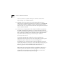
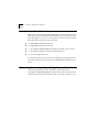
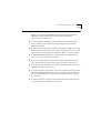
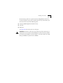
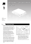
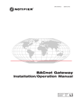
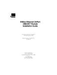
1
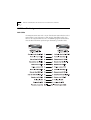
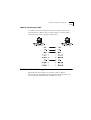
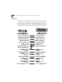
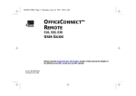
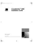
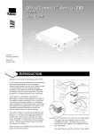
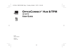
®
Part No. 980/000045/001
Published June 1996
ACCESSBUILDER 7000
BRIDGE/ROUTER MODULE
USER GUIDE
3Com Corporation
■
5400 Bayfront Plaza
■
Santa Clara, California
■
95052-8145
© 3Com Europe Ltd, 1996. All rights reserved. No part of this documentation may be reproduced in any form or
by any means or used to make any derivative work (such as translation, transformation, or adaptation) without
permission from 3Com Europe Ltd.
3Com Europe Ltd. reserves the right to revise this documentation and to make changes in content from time to
time without obligation on the part of 3Com Europe Ltd to provide notification of such revision or change.
3Com Europe Ltd provides this documentation without warranty of any kind, either implied or expressed,
including, but not limited to, the implied warranties of merchantability and fitness for a particular purpose.
3Com may make improvements or changes in the product(s) and/or the program(s) described in this
documentation at any time.
UNITED STATES GOVERNMENT LEGENDS:
If you are a United States government agency, then this documentation and the software described herein are
provided to you subject to the following restricted rights:
For units of the Department of Defense:
Restricted Rights Legend: Use, duplication or disclosure by the Government is subject to restrictions as set forth in
subparagraph (c) (1) (ii) for restricted Rights in Technical Data and Computer Software clause at 48 C.F.R.
52.227-7013. 3Com Europe Limited, Merchants’ House, Wilkinson Road, Cirencester, Gloucestershire, GL7 1YT
United Kingdom.
For civilian agencies:
Restricted Rights Legend: Use, reproduction or disclosure is subject to restrictions set forth in subparagraph (a)
through (d) of the Commercial Computer Software - Restricted Rights Clause at 48 C.F.R. 52.227-19 and the
limitations set forth in 3Com Corporation’s standard commercial agreement for the software. Unpublished rights
reserved under the copyright laws of the United States.
If there is any software on removable media described in this documentation, it is furnished under a license
agreement included with the product as a separate document, in the hard copy documentation, or on the
removable media in a directory file named LICENSE.TXT. If you are unable to locate a copy, please contact 3Com
and a copy will be provided to you.
Unless otherwise indicated, 3Com registered trademarks are registered in the United States and may or may not
be registered in other countries.
3Com, AccessBuilder, Boundary Routing, LANplex, LanScanner, LinkBuilder, NETBuilder, NETBuilder II, Parallel
Tasking, ViewBuilder, EtherDisk, EtherLink, EtherLink Plus, EtherLink II, SmartAgent, TokenLink, TokenLink Plus,
TokenDisk and Transcend are registered trademarks of 3Com Corporation. 3TECH, CacheCard, FDDILink, FMS,
NetProbe and Star-Tek are trademarks of 3Com Corporation. 3ComFacts is a service mark of 3Com Corporation.
CompuServe is a registered trademark of CompuServe, Inc.
Corporation. Novell and NetWare are registered trademarks of Novell Inc. Windows is a trademark of Microsoft
Corporation. VT100 is a registered trademark of Digital Equipment Corporation.
Other brand and product names may be registered trademarks or trademarks of their respective holders.
IMPORTANT SAFETY INFORMATION
WARNING: Warnings contain directions that you must follow for your
personal safety. Follow all instructions carefully.
Please read carefully and thoroughly the following information before
installing the AccessBuilder 7000 Bridge/Router Module:
■
Exceptional care must be taken during installation and removal of the
module.
■
The safety status of the interconnection port on this equipment are as
follows:
Ports identified by the label ISDN = TNV
Ports identified by the labels MANAGER, LAN and WAN = SELV
TNV (telecoms network voltage) is a circuit which under normal
operating conditions carries telecommunication signals.
SELV (safety extra low voltage) is a secondary circuit which is designed
and protected so that under normal and single-fault conditions, the
voltage between any two accessible parts does not exceed a safe value
(42.2 V peak or 60 V DC).
Only connect apparatus complying with the relevant interface
requirements to the ports on this unit.
WARNING: Twisted Pair RJ45 data port. This is a shielded RJ45 data
socket. It cannot be used as a telephone socket. Only connect RJ45 data
connectors to this socket.
WICHTIGE SICHERHEITSHINWEISE
ACHTUNG: Die Warnungen enthalten Anweisungen, die Sie zur
eigenen Sicherheit zu befolgen haben.
Lesen Sie bitte die folgenden Informationen sorgfältig durch, bevor Sie
den AccessBuilder 7000 Bridge/Router Module einbauen:
■
Auf besondere Vorsicht muß während des Ein- und Ausbaus des
Einheits geachtet werden.
■
Der Sicherheitsstandard der Anschlüsse fuer dieses Gerät sind wie folgt:
Anschlüsse bezeichnet mit ISDN = TNV
Anschlüsse bezeichnet mit MANAGER, LAN und WAN = SELV
TNV (Telecoms Network Voltage - Spannung des
Telekommunikationsnetzwerks) ist ein Anschluss, der unter normalen
Umständen Telekommunikationssignale enthält .
SELV (Safety Extra Low Voltage - Extra Sicherheitsspannung) ist ein
weiterer Anschluss, der unter normalen Umständen und
Fehlerkonditionen entworfen und gesichert wurde, so dass die
Spannung zwischen zwei erreichbaren Teilen kein gefährliches Niveau
erreicht (42.2V max. oder 60V DC).
An den Anschlussbuchsen der Geräte dürfen nur die dafür
vorgesehenen Anschlüsse verwendet werden.
ACHTUNG: gedrehte paarfache RJ45 Datenanschluss. Es ist eine
abgeschirmte RJ45 Datenanschlußbuchse. Sie darf nicht als
Telefonanschluß verwendet werden. Verbinden Sie nur RJ45
Datenstecker mit diesem Anschluss.
L’INFORMATION DE SÉCURITÉ
IMPORTANTE
AVERTISSEMENT: Les avertissements contiennent les instructions que
vous devez suivre pour votre sécurité personnelle. Suivre toutes les
instructions avec soin.
Veuillez lire à fond l’information suivante avant d’installer le moyeu:
■
Le soin exceptionnel doit être pris pendant l’installation et l’enlèvement
du moyeu.
■
Les normes de sécurité des ports d'interconnexion sur cet équipement
sont les suivants:
Les ports marqués par les etiquettes ISDN = TNV
Les ports marqués par les etiquettes MANAGER, LAN et WAN = SELV
TNV (Telecoms Network Voltage - tension réseau de
télécommunications) est un circuit qui dans des conditions
d'opérations normales, transfert les signeaux télécoms.
SELV (Safety Extra Low Voltage - tension de sécurité extra-réduite) est
un circuit secondaire désigné et protègé qui dans des conditions
normales et de fautes uniques, assure que la tension entre deux
éléments accessibles n'accedéra pas un niveau de sécurité (42.2V max.
ou 60 V DC).
Connecter uniquement des unités conformes aux normes relatives des
interfaces de cet équipement.
AVERTISSEMENT: Le port de données RJ45 de paire tordue. Ceux-ci
est un socle de données RJ45 blindé. Il ne peut pas être utilisé comme
socle de téléphone. Seulement brancher les connecteurs de données
RJ45 à ce socle.
CONTENTS
IMPORTANT SAFETY INFORMATION
WICHTIGE SICHERHEITSHINWEISE
L’INFORMATION DE SÉCURITÉ IMPORTANTE
ABOUT THIS GUIDE
Introduction 1
How to Use This Guide 2
Conventions 3
Additional Safety Information
4
1 BRIDGE/ROUTER MODULE
Introduction 1-1
Benefits of ISDN 1-2
Using ISDN to Support Leased Line WAN Circuits 1-3
Principal Features 1-4
Typical Applications 1-5
Novell Network 1-5
IP Host on the Same IP Network 1-7
IP Host on Another IP Network 1-9
Internet or PPP Router 1-10
Multiple Connections from a Single Site 1-11
Pack Contents Checklist 1-12
Registering Ownership of your Bridge/Router Module 1-12
Pre-installation Requirements 1-13
2 INSTALLATION AND OPERATION
Overview 2-1
Installing The Module 2-2
BRI Bridge/Router Module 2-2
PRI Bridge/Router Module 2-2
Installation 2-2
Installing the Rear Card 2-4
Installing the Front Card 2-5
Connecting the Cables 2-6
ISDN Ports 2-6
LAN Ports 2-6
Manager 2-6
WAN Ports 2-7
Front Panel LEDs 2-8
BRI Bridge/Router 2-8
PRI Bridge/Router 2-9
Monitoring ISDN Line Usage 2-10
Configuring the Bridge/Router Module
Setting Up a WAN Link 2-11
2-10
3 TROUBLESHOOTING
Troubleshooting Guide 3-1
Management Problems 3-1
POWER LED Does Not Light 3-2
ISDN/CHANNEL LEDs Do Not Light 3-2
Other LEDs Do Not Light 3-2
Bridge/Router Does not Connect to the Remote Device
Bridge/Router Disconnects While On-line 3-2
3-2
A BRIDGE/ROUTER SPECIFICATION AND CABLE PIN
ASSIGNMENTS
Specifications A-1
LAN Connector Interfaces A-1
WAN Connector Interface A-1
ISDN Connector Interface A-1
BRI Bridge/Router Module A-1
PRI Bridge/Router Module A-1
Management Connector Interface A-2
Bridge Characteristics A-2
Performance A-2
Approvals A-3
Physical Description A-3
LAN Port Pin Assignments A-4
AUI Cable A-4
10BaseT Connecting Cable A-5
ISDN Port Cable Pin Assignments A-5
WAN Port Cable Pin Assignments A-6
X.21/V.11 A-6
V.24/V.28 A-7
V.35/V.36 A-8
Management Port Cable Pin Assignments A-9
B TECHNICAL SUPPORT
On-line Technical Services B-1
3Com Bulletin Board Service B-1
Access by Modem B-1
Access by ISDN B-2
World Wide Web Site B-2
Support from Your Network Supplier B-3
Support from 3Com B-4
Returning Products for Repair B-5
INDEX
LIMITED WARRANTY
FCC CLASS A VERIFICATION STATEMENT
ABOUT THIS GUIDE
Introduction
This guide describes the features, installation and configuration of the
AccessBuilder 7000 Bridge/Router Module. There are two versions of
this module:
■
AccessBuilder 7000 BRI Bridge/Router Module - 3C400080
■
AccessBuilder 7000 PRI Bridge/Router Module - 3C404085
These modules are installed and configured in the same way. The PRI
Bridge/Router Module is not connected to ISDN directly however, but
connects through the AccessBuilder 7000 PRI Interface Module.
This guide assumes that you have installed your AccessBuilder 7000
Access Concentrator and that the ISDN lines to which you want to
connect are installed and operational.
This guide does not cover configuration and management of the
Bridge/Router Module. For this information, see the AccessBuilder ISDN
Access Router Software Reference guide.
2
ABOUT THIS GUIDE
How to Use This Guide
This table shows where to find specific information:
If you are looking for information on:
Turn to:
The Bridge/Router Module’s features and typical
uses.
Chapter 1
Installation and descriptions of the front panel
LEDs and rear panel connectors.
Chapter 2
Troubleshooting and problem solving.
Chapter 3
Technical Information and cable specifications.
Appendix A
Technical Support.
Appendix B
Conventions
Conventions
The icon conventions that are used throughout this guide are:
Icon
Type
Description
Information Note
Information notes call attention to
important features or instructions.
Caution
Cautions alert you to personal safety
risk, system damage, or loss of data.
Warning
Warnings alert you to the risk of
severe personal injury.
The text conventions used in this guide are:
Convention
Description
“Enter” vs. “Type”
When the word “enter” is used in this guide,
it means type something, then press the
[Return] or [Enter] key. Do not press the
[Return] or [Enter] key when an instruction
simply says “type.”
Text represented as
This typeface is used to represent
screen display displays on your screen, for example:
Enter the unit’s IP address:
Text represented as
commands
This typeface is used to represent
commands that you enter, for example:
CO IS NU
Keys
When specific keys are referred to in the
text, they are called out by their labels, such
as “the Return key” or “the Escape key,” or
they may be shown as [Return] or [Esc].
If two or more keys are to be pressed
simultaneously, the keys are linked with a
plus sign (+), for example:
Press [Ctrl]+[Alt]+[Del].
Italics
Italics are used to denote new terms or
emphasis.
3
4
ABOUT THIS GUIDE
Additional Safety Information
See also the Important Safety Information at the front of this guide.
When using the unit, observe the following safety information:
■
Retain this user’s guide for later use and pass it on in the event of
change of ownership of the unit.
■
Protect the unit from sudden, transient increases and decreases in
electrical power by fitting an in-line surge suppressor or
uninterruptable power supply.
■
Products manufactured by us are safe and without risk provided they
are installed, used and maintained in good working order in
accordance with our instructions and recommendations.
■
If any of the following conditions occur, isolate the electricity supply
and refer to your 3Com reseller.
■
If the module begins to make an odd noise, smell or smoke.
■
If the module shows signs of a distinct change in performance.
■
Do not spill food or liquids on the unit. If the unit gets wet, isolate the
electrical supply and contact your 3Com reseller.
■
Do not push any objects into the openings of the unit. Doing so can
cause fire or electric shock by shorting out internal components.
■
oBe sure nothing rests on the module’s system cables and that the
cables are not located where they can be stepped on and cause
damage to the unit.
■
Keep the unit away from radiators and heat sources.
■
Install the unit in a clean area that is free from dust or extreme
temperatures.
■
This product complies with the electro-magnetic compatibility (EMC)
requirements of EN 55022 Class A and EN 50082 (susceptibility) when
the following prerequisites are observed;
■
the WAN port must be attached to a screened digital cable.
■
the ISDN cable must be used in conjunction with a three turn ferrite.
Additional Safety Information
5
■
This unit contains a lithium battery which is attached to a microchip on
the printed circuit board. The defective battery must be disposed of
safely in-line with the manufacturers instructions.
■
Interconnecting directly, or by way of other apparatus, to ports
complying with SELV requirements may produce hazardous conditions
on the network. Advice should be sought from a competent engineer
before such a connection is made.
6
ABOUT THIS GUIDE
1
BRIDGE/ROUTER MODULE
Introduction
This chapter outlines the features and uses of the AccessBuilder 7000
Bridge/Router Module when installed in the AccessBuilder 7000 Access
Concentrator chassis. There are two versions of the Bridge/Router Module:
■
BRI Bridge Router Module – Connects directly to two Basic Rate ISDN
lines (four ISDN channels) and has two WAN ports for connection to
leased line services.
■
PRI Bridge Router Module – Connects to the Primary Rate ISDN service
through the PRI Interface Module. This module provides up to eight ISDN
channels and has two WAN ports for connection to leased line services.
The bridge/router modules allow geographically separate LAN
workgroups and remote office users, to connect to central computing
facilities through either, a dial-up on demand connection over the
integrated services digital network (ISDN), or permanently connected
leased lines.
The Bridge/Router Module also has two ports for connection over
permanent leased line WAN connections, also available from your
telephone carrier organization. Leased lines are available to work at a
range of speeds which incur higher costs the higher the line speed. The
benefit of leased lines is their permanence and fixed cost. No dialling is
required, but unlike ISDN, you pay a fixed cost regardless of whether you
transfer little data or high volumes of data 24 hours a day.
1- 2
CHAPTER 1: BRIDGE/ROUTER MODULE
Typically, the Bridge/Router module is used to interconnect LANs
running protocols such as Transmission Control Protocol/Internet
Protocol (TCP/IP) or Novell Internetwork Packet Exchange (IPX). The
module offers full LAN-to-LAN connectivity at speeds up to 64 Kilobits
per second (Kbps) on each ISDN channel (128 Kbps in total) and up to
2 Megabits per second (Mbps) on the WAN port.
The maximum bandwidth of the Bridge/Router Module is 2 Mbps. If you
have a single leased-line link running at 2 Mbps connected to a WAN
port, you must disable the ISDN ports and the second WAN port.
In the USA, some ISDN services run over 56 Kbps channels. Basic Rate
ISDN therefore offers connectivity of 112 Kbps in total.
Benefits of ISDN
ISDN is an extension of the national and international public switched
telephone network, which offers a digital end-to-end telecommunication
system, providing a better quality service than available using the analog
telephone network. The principal benefits of ISDN are:
■
Fast call setup times, typically taking less than one second for national
calls.
■
Greater bandwidth with multiple channels.
The basic rate service, often referred to as ISDN 2, carries two 64 Kbps
(possibly 56 Kbps in USA) user channels, called B channels and one
16 Kbps control channel called the D channel. The line service is
presented into the customers premises through a standard RJ45 socket.
The PRI Bridge/Router module is designed to operate with Primary Rate
ISDN services provided to the AccessBuilder 7000 through the PRI
Interface Module and supports up to eight 64 Kbps (possibly 56 Kbps in
USA) user channels.
A significant aspect of the ISDN service is that it can be provided over
the same wiring that was installed for the original telephone service.
Therefore, ISDN can be made available relatively cheaply almost
anywhere that previously had access to the analog system. The cost of
Introduction
1-3
installation and rental of ISDN lines has dropped to the point where it is
extremely attractive as regards cost and performance.
Using ISDN to Support Leased Line WAN Circuits
ISDN provides an ideal service to connect remote LANs. To be effective,
the connecting bandwidth needed is at least 56 Kbps to achieve a realistic
throughput. Slower speed links can be used but usually only when usage
is low and infrequent, or if higher speed circuits cannot be provided.
Leased digital point-to-point circuits can still be cost effective if usage
spans many hours per day. However as ISDN tariffs reduce, this balance
also changes. ISDN can be used to provide effective backup of these
point-to-point WAN circuits in two ways.
■
Firstly, if the point-to-point circuit fails, an ISDN channel can be
dialled-up automatically and quickly, to provide an alternative path to
the remote unit.
■
Secondly, if the leased circuit becomes heavily loaded due to peaks in
the traffic between remote bridges or routers, additional bandwidth
can be automatically dialled-up to supplement the bandwidth of the
leased circuit. The interconnected bridges would then treat the leased
line and ISDN channel as parallel links, sharing the load across the two.
1- 4
CHAPTER 1: BRIDGE/ROUTER MODULE
Principal Features
The principal features of the Bridge/Router Module are:
■
Easy to install, configure and support.
■
BRI Bridge/Router Module – 2 x Basic Rate Interface ISDN, 2B+D port,
supporting Basic Rate interface of two 64 Kbps channels (or possibly two
56 Kbps channels in the USA) and a 16 Kbps control channel. Available
with a U or S ISDN interface.
■
PRI Bridge/Router Module– Primary Rate Interface ISDN supporting up
to eight 64 Kbps channels connecting to ISDN through the PRI
Interface Module.
■
Two leased line wide area network (WAN) access ports.
The PRI Bridge/Router Module supports a total of eight ISDN/WAN ports. If
both WAN ports are to be used, only six ISDN channels can be connected.
The maximum bandwidth of the Bridge/Router Module is 2 Mbps. If you
have a single leased-line link running at 2 Mbps connected to a WAN port,
you must disable the ISDN ports and the second WAN port.
■
Three standard Ethernet LAN connections.
■
Data terminal equipment (DTE) management port.
■
Support for full IP and IPX routing.
■
Protocol transparent bridging.
■
Sophisticated data packet filtering to provide network security.
■
Provides NetWare protocol spoofing.
■
Data compression based on an optimized Lempel Ziv algorithm.
■
Scalable Router Clustering (SRC) to optimize ISDN routing and line
usage.
■
Remote and local management.
■
Flash erasable programmable read-only memory (EPROM), allowing the
remote upgrading of the units operating system.
■
Uses simple network management protocol (SNMP) and provides
management information base (MIB) II support.
Typical Applications
1-5
Typical Applications
The Bridge/Router module is ideally suited for large central sites providing
access for remote users to central site services over ISDN or leased lines.
This section describes four of the most common applications of the
Bridge/Router module using ISDN. All of these configurations can be
carried out using the Quick Configuration option and no further
configuration is necessary to make the unit operational. However, you
may want to fine tune the performance of the unit. For more
information about configuring the Bridge/Router Module, see the
AccessBuilder ISDN Access Router Software Reference guide.
The four typical applications are:
■
Connecting to a Novell Network.
■
Connecting to an IP host on the same IP network.
■
Connecting to an IP host on another IP network.
■
Connecting to the Internet or a PPP router.
You may need to combine two or more of these applications to provide
full connectivity to your network. This is easily done by repeating the
Quick Configuration option as many times as is needed.
Novell Network
Many organizations base their local area networks on Novell NetWare
servers and users may need to access information stored on servers in
other locations. If you are using ISDN to connect to the remote site, you
can configure the unit to automatically call and connect to remote
Novell servers when connection is required.
During configuration, once you have entered the ISDN number for the
remote site, the unit makes a call to the remote site and autodiscovers
the Novell servers on that network. It is then able to autocall the
remote site whenever a connection to one of the remote servers is
requested. To the user at the local site it will appear as though the
server is on the same network.
1- 6
CHAPTER 1: BRIDGE/ROUTER MODULE
When no data is being passed between the workstation and server, the
Bridge/Router Module closes the ISDN connection and the units at
each end of the link spoof the Novell IPX protocol so that both the
workstation and server believe the connection is still valid. As soon as
the unit identifies that data needs to be passed to the server, the ISDN
connection is re-established without the user being aware of ever
being disconnected. In this way ISDN calls are kept to a minimum.
Figure 1-1 Connecting To A Remote Novell Network
In the example shown in Figure 1-1, the Main Site is connected to a
Remote Site. The Main Site provides many network facilities required by
remote users. The Remote Site shown has several workstations and a
server but could equally consist solely of workstations or even a single
workstation (such as in the case of a homeworker) but could be a similar
sized site to the Main Site.
If you are connecting to the remote site over a WAN leased line link, the
Bridge/Router Module has no need to spoof the IPX protocol as there is a
permanent connection in place. Once the unit has determined that the
server is on the Remote Site all data between the server and workstation
is passed over the link.
Typical Applications
1-7
IP Host on the Same IP Network
If your organization operates a TCP/IP network and needs to extend the
IP network over geographically remote sites, it is possible to bridge the
network using the Bridge/Router Module. It is only possible to bridge
where both sites have the same network address and the devices are
on the same subnet. In a class C IP address, the network address is the
first three groups of numbers. For example:
192.100.100.xxx
where xxx represents the host ID of the individual devices on the subnet.
See “IP Addresses” in Appendix A for more information about addresses.
Typically IP bridging would be used to connect a back office or home office
into a main site. Any further network connections would be carried out
from the main site. An example of such a network is shown in Figure 1-2.
During configuration, you enter the ISDN number and the IP addresses
of any hosts to which you want to connect. In the example in
Figure 1-2, the IP address of the host 191.100.100.100 is used. Only
when data destined for this device is received by the Bridge/Router
Module, is a call made to the remote site.
Figure 1-2 IP Bridged Network
1- 8
CHAPTER 1: BRIDGE/ROUTER MODULE
There are some issues about which you should be aware when
implementing an IP bridging solution.
■
Although calls to the remote site are only generated when data is
addressed to a specific IP host or hosts (in our example, 191.100.100.100),
any data that cannot be identified as local is also passed over the link
while it is open. This can prevent the link from closing after the intended
data has been transferred.
■
Some devices and applications (for example autodiscovery programs
on SNMP managers) poll all devices on a subnet at regular intervals
and this could lead to frequent ISDN calls if you have entered several IP
hosts to generate autocalls to the remote site. When combined with
the problem described above, you could find your ISDN line
permanently connected.
To avoid this situation you need to be sure that no devices or
applications exist on your local site that could make unnecessary and
costly calls to your remote site. You can also configure the
AccessBuilder units at both ends of the link to implement a Firewall
and/or Call Guillotine to reduce the amount of traffic permitted to pass
across the link. See the AccessBuilder ISDN Access Router Software
Reference guide for more information about these features.
Alternatively, you may wish to configure the module to operate as a
router to prevent this problem occurring altogether. This however,
requires that each site consists of separate subnets. See the next
section for more information about IP routing.
Typical Applications
1-9
IP Host on Another IP Network
Most organizations using TCP/IP protocols on their network, choose to
subnet remote sites or even to have them on different networks. This
requires that connections to remote sites are routed rather than bridged.
The advantage of routing over bridging is that calls to the remote site are
only made when data is specifically addressed to a remote network.
Bridging passes any data not known to be for the local network to the
remote network whether that is its destination or not.
Because the ISDN number can be associated with a remote network
rather than just a specific IP host, any data for the remote network can
generate an autocall and be routed through the AccessBuilder. If you
need to connect to IP hosts on several networks, you will need to use
routing to be able to communicate with the different hosts.
The example shown in Figure 1-3 shows the Local Site connected to two
Remote sites over ISDN. All sites are connected using AccessBuilder units.
Figure 1-3 IP Routed Network
1-10
CHAPTER 1: BRIDGE/ROUTER MODULE
Internet or PPP Router
Some small businesses need high-speed connections into the Internet or
need to connect to large global networks used by larger organizations.
When communicating with another AccessBuilder ISDN bridge/router, the
unit uses FastConnect, its own proprietary high speed protocol. However, in
order to connect with other routers it needs to be configured to use the
slower PPP protocol. PPP is used by many other routers.
Increasingly Internet service providers are offering access to the Internet
over ISDN via an ISDN router. PPP routing over ISDN allows a simple
cost-effective connection to the Internet or into a large organization’s
global network.
Figure 1-4 PPP Connections To The Internet and Corporate Network
Typical Applications
1-11
Multiple Connections from a Single Site
In some instances it is likely that you will need to connect to Novell servers
on one site, IP hosts on the same remote site or possibly a different
remote site and a connection into the Internet. This can all be achieved
by running the Quick Configuration several times until all the desired
types of connection have been configured. The only thing you need to
be aware of is that you cannot bridge and route the same protocol on
the same AccessBuilder bridge/router.
The local site shown in Figure 1-5 is a small business that needs data links
to several of its clients and a connection to the Internet. It has an IPX
connection to access information on one client’s NetWare server and IP
routed connections to several IP hosts at different clients’ sites. Finally,
there is a connection to the local Internet service provider’s PPP router
giving fast access to the Internet. All connections can be set up with an
autocall so that connections to the remote sites are made as soon as the
Bridge/Router Module identifies data not destined for the local network.
Figure 1-5 Multiple Connections From A Single Site
1-12
CHAPTER 1: BRIDGE/ROUTER MODULE
Pack Contents Checklist
Before you install your Bridge/Router Module, check the contents of the
box against the pack contents checklist below. If any of the items have
been damaged in transit or are missing, then contact the 3Com reseller
from whom the equipment was purchased.
■
1 x Bridge/Router Module front card.
■
1 x Bridge/Router Module back card.
■
1 x AccessBuilder 7000 Bridge/Router Module User Guide (This manual).
■
1 x AccessBuilder ISDN Access Router Software Reference.
■
1 x warranty registration card.
It is important that you save the box and protective packing material in
case you need to store, or transport your Bridge/Router Module in the
future.
Registering Ownership of your Bridge/Router Module
A warranty registration card is enclosed in the box with your
AccessBuilder 7000 Bridge/Router Module. Please take a few moments
before commencing the installation to fill in the card and post it to us.
Pre-installation Requirements
1-13
Pre-installation Requirements
Before you install the Bridge/Router Module into the AccessBuilder
7000 Access Concentrator chassis, check that the following
requirements have been met:
■
The AccessBuilder 7000 Access Concentrator must already be fitted
with its power supply module(s) and the Management Controller
Module if required.
■
The rack unit into which you install the AccessBuilder 7000 must allow
for the door to be fully opened to remove existing modules or to install
new modules. During normal operation the door must remain closed.
■
The BRI Bridge/Router Module is two slots wide. You need two free
slots in the chassis to install the module.
■
You have suitable cables for connection to your LAN, WAN and ISDN
ports. Pin-outs for the cables required can be found in Appendix A
■
A transceiver connected to your network cabling and AUI cable if the
10Base5 connector is to be used.
■
A standard ISDN line wall socket to connect the ISDN cable to the ISDN
port of the BRI Bridge/Router module. If a suitably sited wall socket is
not already available, then contact your telecommunications supplier
for assistance.
■
The ISDN telephone number of the remote ISDN unit in order to carry
out the connection configuration procedure.
1-14
CHAPTER 1: BRIDGE/ROUTER MODULE
2
INSTALLATION AND OPERATION
Overview
This chapter describes how to install the AccessBuilder 7000 BRI
Bridge/Router module and/or the AccessBuilder 7000 PRI Bridge/Router
module into the AccessBuilder 7000 Access Concentrator chassis and
how to read the LEDs on the module’s front panel.
Ensure you read the safety information at the front of this guide before
commencing installation of the AccessBuilder 7000 Bridge/Router Module.
Check that you have met all the pre-requisites out-lined in Chapter 1
and that you have access to the ISDN lines to connect your module(s).
2-2
CHAPTER 2: INSTALLATION AND OPERATION
Installing The Module
Before installing the module, read the Safety Information at the front of
this guide.
BRI Bridge/Router Module
The AccessBuilder 7000 BRI Bridge/Router Module is a two slot wide
module and can be installed in any two adjacent free slots. The single
width rear card is installed in the right-most slot of the two slots, when
looking at the rear of the AccessBuilder 7000.
PRI Bridge/Router Module
The AccessBuilder 7000 PRI Bridge/Router Module is a single slot
module and can be installed in any of the AccessBuilder 7000’s slots.
Although the rear card contains two ISDN ports, these are not used as
the ISDN connections are made through the PRI Interface Module.
Installation
An AccessBuilder 7000 module consists of two parts; a front card and a
back card that both connect to the chassis’ backplane. It is recommended
that you install the module’s rear card into the chassis first and secure it in
place with the screws removed from the blanking plate.
The installation of the Bridge/Router Module into the AccessBuilder
7000 chassis takes place in three distinct operations:
■
Installing the rear card.
■
Installing the front card.
■
Connecting cables to the DTE and Line ports. See “Connecting the
Cables” on page 2-6 for more information about connecting to the ports.
Modules within the AccessBuilder 7000 system are designed to be hot
swapable. It is not necessary to turn off the AccessBuilder 7000’s power
supply unit to install either the front card or rear card of the
Bridge/Router Module.
Installing The Module
2-3
No connecting cables are supplied with the Bridge/Router Module as
standard. Check that you have suitable cables for any connections you
want to make to any of the following ports:
■
ISDN port (BRI Bridge/Router Module only).
■
LAN port.
■
WAN port
See Appendix A for cable pin-outs and types.
CAUTION: At all times, take care not to touch any of the connectors or
components on the cards to avoid damage by static electricity. Handle
the cards by the handles or by their edges. Use an anti-static wrist strap
during installation if you have one available.
2-4
CHAPTER 2: INSTALLATION AND OPERATION
Installing the Rear Card
Figure 2-1 Installing The Rear Card
1 Locate the rear slot equivalent to the front slot into which you will
install the front card.
2 Remove the metal blanking plate at the rear of the chassis and retain
the screws.
Retain the blanking plate. If you remove the module, the blanking plate
must be refitted to the chassis to aid the circulation of cooling air and
to prevent dust and debris entering the unit.
3 Insert the rear card with the RJ45 ports at the top of the card and slide
it home along the guide rails so that it connects with the backplane.
4 Secure the rear card into position using the screws from the blanking plate.
Installing The Module
2-5
Installing the Front Card
Figure 2-2 Example Of Installing A Front Card
1 Locate the front slot in the AccessBuilder 7000 chassis equivalent to the
rear slot in which you have already installed the rear card.
2 Insert the front card into the slot ensuring that it is centered along the
guide rails.
3 Use the module’s handles to push the card gently but firmly home into
the chassis and lock it into place.
4 Close and lock the chassis door.
To remove the card, unlatch the handles to free the card from the back
plane and pull the front card free from the chassis using the handles.
2-6
CHAPTER 2: INSTALLATION AND OPERATION
Connecting the Cables
The ports on the rear panel are described below in order from top to
bottom of the rear card.
If you are using the PRI Bridge/Router Module, you do not connect to ISDN
using the ISDN ports on the rear card. The ISDN calls are routed along the
chassis’ backplane to the PRI Interface Module. See the AccessBuilder 7000
PRI Interface Module User Guide for more information.
ISDN Ports (1&2)
1
2
There are two ISDN ports supporting two ISDN Basic Rate
lines on the BRI Bridge/Router Module. Connect these
ports to your ISDN wall box.
LAN Ports
3
There are three LAN connectors. Only one LAN port can
be used at any one time.
4
BNC (3) – For connection to Thin Ethernet (10Base2).
RJ45 (4) – For connection to 10BaseT networks.
5
6
7
8
AUI (5) – For connection to any cabling media using an
AUI cable and transceiver.
The two LEDs (6) show LAN activity. Yellow shows Tx
traffic and green shows Rx traffic. The rate at which the
LEDs flash indicate the volume of LAN traffic.
Manager (7)
9
The Manager port enables a management PC or terminal
to be connected to the module using the 9-pin D-type to
RJ11 Serial Manager cable supplied with the unit. The port
provides VT100 terminal emulation, running at 9600 bps.
See Appendix A for more information about cables.
Installing The Module
2-7
You also need a proprietary communications software package such as
Windows ‘Terminal’ to communicate with the module’s management
system. See the AccessBuilder ISDN Access Router Software Reference for
more information about managing the module.
WAN Ports (8 & 9)
These ports are used to provide connection to a WAN over a private
leased line. The port terminates with a SCSI connector. This port
supports any of the CCITT data transmission standards; X.21/V.11
V.24/V.28 (RS232), and V.35/V.36 at data transfer rates up to 2 Mbps.
Provided that connection cables that follow these standards are used,
the unit automatically detects the type of interface that the port is
required to support, and configures it accordingly.
Refer to Appendix A for information about the WAN interface cables
required. Suitable cables are available from your 3Com reseller as spare
parts, refer to Appendix A for the required item part number.
The PRI Bridge/Router Module supports up to eight ISDN channels.
However, if you use a WAN port, one less ISDN channel can be supported.
If both WAN ports are used, a maximum of six ISDN channels can be
supported by the module.
2-8
CHAPTER 2: INSTALLATION AND OPERATION
Front Panel LEDs
This section describes the Bridge/Router Module’s LEDs. The LEDs are
slightly different for the BRI Bridge/Router Module and the PRI
Bridge/Router Module.
Most of the LEDs can only be seen when the front door of the chassis is
open. When the door is closed, only the PWR, ALARM, ALERT and TEST
LEDs can be seen. These LEDs show the status of the whole module.
BRI Bridge/Router
CHANNEL 1 to 6 Channels 1 and 2 show the status of the WAN1 and
WAN2. When lit, the LED shows that WAN port is configured and up.
When flashing, the LED shows that WAN port is configured and down.
Channels 3 to 6 show the status of the ISDN channels. When lit, the
LED shows the ISDN channel is configured and up.
PWR (Power) When lit indicates that the module is receiving power
from the chassis’ backplane and that the power circuits are
functioning correctly.
ALARM Lights to indicate that an event has occurred which has
been configured to raise an alarm. See the AccessBuilder 7000
Access Concentrator User Guide for more information.
ALERT Lights to indicate that an event has occurred which has
been configured to raise an alert. See the AccessBuilder 7000 Access
Concentrator User Guide for more information.
LAN ACTIVITY When lit shows that LAN activity has been detected
within the last 10 seconds. If the LED flashes, it shows the LAN is
connected but no activity has been detected for 10 seconds or longer.
MANAGER When lit, a management terminal is connected to the
module.
RUN When lit indicates the module’s onboard software is running.
Push Buttons Push both buttons together to reset the module
and restart it using the previously saved configuration.
Front Panel LEDs
2-9
PRI Bridge/Router
CHAN 1 and 2 Channels 1 and 2 show the status of the two WAN ports,
WAN1 and WAN2. When lit, the LED shows that WAN port is configured
and up. When flashing, it shows that WAN port is configured and down.
ISDN When lit shows that one or more ISDN channels are in use.
PRI FOUND Indicates that a PRI Interface Module has been identified in
the chassis.
SRC MASTER When lit shows that this module is the SRC master. If the
LED is flashing, it indicates a new SRC master is being chosen.
SRC SLAVE When lit shows that this module is the SRC slave. If the LED
is flashing, it indicates a new SRC master is being chosen.
PWR (Power) When lit indicates that the module is receiving power
from the chassis’ backplane and that the power circuits are functioning
correctly.
ALARM Lights to indicate that an event has occurred which has been
configured to raise an alarm. See the AccessBuilder 7000 Access
Concentrator User Guide for more information.
ALERT Lights to indicate that an event has occurred which has been
configured to raise an alert. See the AccessBuilder 7000 Access
Concentrator User Guide for more information.
TEST Lights during the power-on self test.
LAN When lit shows that LAN activity has been detected within the last
10 seconds. If the LED flashes, it shows the LAN is connected but no
activity has been detected for 10 seconds or longer.
MANAGER When lit, a management terminal is connected to the module.
RUN When lit indicates the module’s onboard software is running.
Push Buttons Push both buttons together to reset the module and
restart it using the previously saved configuration.
2-10
CHAPTER 2: INSTALLATION AND OPERATION
Monitoring ISDN Line Usage
After you have first configured the module for use with ISDN, it is
important to monitor ISDN line usage to ensure that the unit is
working in the way you expect.
Check the ISDN and CHANNEL LEDs to ensure that unexpected calls are
not being made or that connections are not remaining open when you
expect them to have closed. As in a conventional telephone call, charges
are made regardless of what is sent down the line until the call is dropped.
If you want to ensure that ISDN line usage is limited, set up ISDN
Timebands or set the Maximum Call Duration parameter. See the
AccessBuilder ISDN Access Router Software Reference guide for more
information on these features.
You can also monitor outbound calls using the ST IS command and
check the history of each ISDN channel.
Configuring the Bridge/Router Module
The Bridge/Router Module management system can be accessed
through a PC or terminal connected either to the Management
Controller Module or directly to the Management port of the module.
In most circumstances you can configure the module for use with ISDN
using the Quick Configuration option. The following section provides a
quick overview of configuring the module for use with a LAN leased
line connection.
For full details on connecting a PC or terminal to the module and on
configuring and managing the module, see the AccessBuilder ISDN
Access Router Software Reference guide. For details of accessing the
management system through the Management Controller Module, see
the AccessBuilder 7000 Access Concentrator User Guide.
Setting Up a WAN Link
2-11
Setting Up a WAN Link
If you are using the Bridge/Router Module to connect to a remote site
over a leased line link, the initial setup is very simple.
1 Before you power on the unit, connect an appropriate WAN cable to
the WAN ports on the rear of the unit. If you have already powered on
the unit, switch it off and connect the cable.
For information about suitable cables, see Appendix A.
2 Power on the unit and connect to the management system.
3 Type CO STD and then confirm with Y.
The unit automatically configures the WAN ports to the appropriate
line speed.
4 Refer to the AccessBuilder ISDN Access Router Software Reference guide
and edit the WAN port’s configuration as follows:
a From the main menu, enter CO PO.
b Highlight the WAN port you want to edit.
c Enter ED to display the Edit WAN Port screen shown in Figure 2-3.
Figure 2-3 Edit WAN Port Screen
2-12
CHAPTER 2: INSTALLATION AND OPERATION
d If you are routing, edit the Port IP address to set it to UNNUMBERED
or to a valid IP address for the WAN link.
See the AccessBuilder ISDN Access Router Software Reference guide for
more information about using numbered and unnumbered links.
If you are bridging, leave this field at the default setting.
e If necessary, change any of the other parameters to suit your WAN
link. In most cases the defaults can be used.
f Press [CTRL]+[E] to submit this configuration.
The WAN port is now configured and, provided the remote unit’s WAN
port has also been configured, data will be passed across the link.
Enter SAVE at the command prompt to permanently store this
configuration in the unit’s memory.
3
TROUBLESHOOTING
Troubleshooting Guide
In this section we discuss the basic problems that can occur when using
your Bridge/Router Module. If a problem continues to occur, contact your
supplier for assistance.
Management Problems
Can not access the Bridge/Router Module’s Management System
Ensure that the terminal is VT100 specification compliant.
Ensure that the communication setting are:- 9600 bits/s, 8 data bits, 1
stop bit, no parity with flow control set up to None or Optional.
If connecting directly to the management port, ensure that the cable
pin specifications are correctly wired as described in Appendix A.
The [Arrow] keys do not work correctly when trying to select a
Menu item from the Bridge/Router Module’s MMI.
If using the Windows terminal emulator, ensure that the Use function,
Arrow and [Ctrl] Keys for Windows checkbox is not crossed.
3- 2
CHAPTER 3: TROUBLESHOOTING
POWER LED Does Not Light
Make sure that the front and rear cards are pushed fully home, and that
the rack enclosure is powered ON.
ISDN/CHANNEL LEDs Do Not Light
Ensure that the Bridge/Router Module is powered on and that the
POWER LED is lit. Check the connections at both ends of the ISDN cable.
Check that the ISDN port is configured using the CO PO command. See
the AccessBuilder ISDN Access Router Software Reference guide for more
information about this command. If the LED still fails to light, check the
ISDN service by connecting the ISDN port to an alternative ISDN socket. If
all of these options fail, contact your ISDN service provider.
Other LEDs Do Not Light
During normal operation the remaining unit LEDs should light and
extinguish depending on the action being taken. If the LEDs fail to light
in accordance with their function then contact your supplying 3Com
reseller for advice.
Bridge/Router Does not Connect to the Remote Device
Check the connections between the Bridge/Router Module, the LAN
and the ISDN line. Check that the number you are dialling is correct
and that it is connected to a remote device. Check that the remote
device is configured to answer incoming calls.
Bridge/Router Disconnects While On-line
Check for any loose connections between your LAN, Bridge/Router
Module and the ISDN wall socket. Excessive line noise or interference
may also cause an interruption to the line signals in which case you
should dial the remote unit again. If this problem persists, contact your
3Com reseller for advice.
A
BRIDGE/ROUTER SPECIFICATION
AND CABLE PIN ASSIGNMENTS
Specifications
LAN Connector Interfaces
■
10Base2 via a coaxial connector.
■
10BaseT via an RJ45 connector socket for UTP.
■
10Base5 via an AUI connector.
Only one LAN interface can be used at any one time.
WAN Connector Interface
Mini-SCSI female connector, configured to support one of:
■
V.11 (X.21) for speeds up to 2.048 Mbps.
■
V.28 (V.24/RS232) for speeds up to 19.2 Kbps.
■
V.35/V.36 for speeds up to 2.048 Mbps.
ISDN Connector Interface
BRI Bridge/Router Module
2 x RJ45 connector sockets providing a twin interface to a 2B+D basic
rate ISDN service.
PRI Bridge/Router Module
Primary Rate ISDN interface provided by the AccessBuilder 7000 PRI
Interface Module.
A-2
APPENDIX A: BRIDGE/ROUTER SPECIFICATION AND CABLE PIN ASSIGNMENTS
Management Connector Interface
9-way D-type connector to RJ11 for use with a VT100 compliant
terminal or PC.
■
Local and remote terminal management.
■
TCP/IP Telnet menu driven management interface for remote
management.
■
Software upgrades, enhancements and configurations downloadable
from network attached terminal or PC.
■
SNMP MIB II support with private extensions for management of
unique features.
Bridge Characteristics
■
802.3 MAC layer bridge.
■
802.1D spanning tree algorithm.
■
Support for bridge triangulation and link load sharing.
Performance
■
LAN filtering rate: 10000 frames per second.
■
LAN forwarding rate: 4000 frames per second.
ISDN and WAN forwarding rates are dependent on the link speed.
Approvals
A-3
Approvals
This product complies with the electro-magnetic compatibility (EMC)
requirements of EN 55022 Class A and EN 50082 (susceptibility) as long
as the following prerequisites are observed:
■
The WAN port must be attached to a screened digital cable.
■
The ISDN cable must be used in conjunction with a three turn ferrite.
The product carries the CE certification mark to indicate conformance
with the following EU directives:
■
LVD (Low Voltage Directive (Safety) 73/23/EEC.
■
EMC (Electro Magnetic Compatibility) Directive 89/336/EEC.
■
TTE (Telecommunication Terminal Equipment) Directive 91/263/EEC.
The PRI Bridge/Router Module conforms to BS6450 part4, BS7378
part1 and I-CTR4 (Primary Rate ISDN).
The BRI Bridge/Router Module conforms to I-CTR3 (based on NET3 –
ISDN interface).
See also the FCC and CSA statements at the back of this guide.
Physical Description
Power
16V ac, 47 to 63 Hz, 1A max. Typical power consumption 11 Watts.
Environment
Temperature 0 to 40 degrees centigrade operating. -50 to 70 degrees
centigrade storage.
Relative humidity 5% to 95% non-condensing.
Altitude to 3000 meters.
A-4
APPENDIX A: BRIDGE/ROUTER SPECIFICATION AND CABLE PIN ASSIGNMENTS
LAN Port Pin Assignments
AUI Cable
The AUI port terminates with a 15-pin female connector which must be
connected to a transceiver on a LAN using an AUI (drop) cable. This
cable is not supplied with the unit. The following signal characteristics
must be observed when purchasing or fabricating a suitable cable.
ISDN Port Cable Pin Assignments
A-5
10BaseT Connecting Cable
The 10BaseT port terminates with an RJ45 connector which can be
connected to the 10BaseT port on another device. The table below
shows the pin-outs for a straight through cable.
ISDN Port Cable Pin Assignments
Basic Rate ISDN connections use the same cable as 10BaseT
connections. For information on Primary Rate ISDN connections, see
the AccessBuilder 7000 PRI Interface Module User Guide.
A-6
APPENDIX A: BRIDGE/ROUTER SPECIFICATION AND CABLE PIN ASSIGNMENTS
WAN Port Cable Pin Assignments
X.21/V.11
The WAN port terminates with a 26-way miniature SCSI connector.
The port can be configured to support V.11 signalling characteristics at
data transfer rates up to 2.048 Mbps. The WAN port connecting cable is
not supplied with the module. The following signalling characteristics
should be observed when purchasing or fabricating a suitable cable.
WAN Port Cable Pin Assignments
A-7
V.24/V.28
The WAN port terminates with a 26-way miniature SCSI connector.
The port can be configured to support V.24 or V.28 signalling
characteristics at data transfer rates up to 19.2 Kbps. The WAN port
connecting cable is not supplied with the module. The following
signalling characteristics should be observed when purchasing or
fabricating a suitable cable.
A-8
APPENDIX A: BRIDGE/ROUTER SPECIFICATION AND CABLE PIN ASSIGNMENTS
V.35/V.36
The WAN port terminates with a 26-way miniature SCSI connector.
The port can be configured to support V.36 signalling characteristics at
data transfer rates up to 48 Kbps. The WAN port connecting cable is
not supplied with the module. The following signalling characteristics
should be observed when purchasing or fabricating a suitable cable.
Management Port Cable Pin Assignments
A-9
Management Port Cable Pin Assignments
The manager port cable terminates with an RJ11 connector at one end
and a 9-pin male/female D-type connector. The pin-out table below
show the pin outs for this cable.
A-10
APPENDIX A: BRIDGE/ROUTER SPECIFICATION AND CABLE PIN ASSIGNMENTS
B
TECHNICAL SUPPORT
3Com provides easy access to technical support information through
the variety of services described in this appendix.
On-line Technical Services
3Com offers worldwide product support seven days a week, 24 hours a
day, through the following on-line systems:
■
3Com Bulletin Board Service (3ComBBS)
■
World Wide Web site
3Com Bulletin Board Service
3ComBBS contains patches, software, and drivers for all 3Com products,
as well as technical articles. This service is available via modem or ISDN
seven days a week, 24 hours a day.
Access by Modem
To reach the service by modem, set your modem to 8 data bits, no
parity, and 1 stop bit.
B-2
APPENDIX B: TECHNICAL SUPPORT
Call the telephone number nearest you:
Country
Data Rate
Telephone Number
Australia
up to 14400 bps
(61) (2) 9955 2073
France
up to 14400 bps
(33) (1) 69 86 69 54
Germany
up to 9600 bps
(49) (89) 627 32 188 or (49) (89) 627 32
189
Hong Kong
up to 14400 bps
(852) 2537 5608
Italy (fee required)
up to 14400 bps
(39) (2) 273 00680
Japan
up to 14400 bps
(81) (3) 3345 7266
Singapore
up to 14400 bps
(65) 534 5693
Taiwan
up to 14400 bps
(886) (2) 377 5838
U.K.
up to 28800 bps
(44) (1442) 278278
U.S.
up to 28800 bps
(1) (408) 980 8204
Access by ISDN
ISDN users can dial-in to 3ComBBS using a digital modem for fast
access up to 56 Kbps. To access 3ComBBS using ISDN, dial the
following number:
(1) (408) 654-2703
World Wide Web Site
Access the latest networking information on 3Com’s World Wide Web
site by entering our URL into your Internet browser:
http://www.3Com.com/
This service features news and information about 3Com products,
customer service and support, 3Com’s latest news releases, selected
articles from 3TECH™ (3Com’s award-winning technical journal) and
more.
Support from Your Network Supplier
B-3
Support from Your Network Supplier
If additional assistance is required, contact your network supplier.
Many suppliers are authorized 3Com service partners who are qualified
to provide a variety of services, including network planning, installation,
hardware maintenance, application training, and support services.
When you contact your network supplier for assistance, have the
following information ready:
■
Diagnostic error messages
■
A list of system hardware and software, including revision levels
■
Details about recent configuration changes, if applicable
If you are unable to contact your network supplier, see the following
section on how to contact 3Com.
B-4
APPENDIX B: TECHNICAL SUPPORT
Support from 3Com
If you are unable to receive support from your network supplier,
technical support contracts are available from 3Com.
In the U.S. and Canada, call (800) 876-3266 for customer service.
If you are outside the U.S. and Canada, contact your local 3Com sales
office to find your authorized service provider:
Country
Telephone Number
Country
Telephone Number
Australia
(Sydney)
(61) (2) 959 3020
Japan
(81) (3) 33457251
Mexico
(525) 531 0591
0800 71429
Netherlands*
06 0227788
Brazil
(55) (11) 546 0869
Norway*
800 13376
Canada
(905) 882 9964
Singapore
(65) 538 9368
Denmark*
800 17309
South Africa
(27) (11) 803 7404
900 983125
(Melbourne) (61) (3) 653 9515
Belgium*
Finland*
0800 113153
Spain*
France*
05 917959
Sweden*
020 795482
Germany*
0130 821502
Taiwan
(886) (2) 577 4352
Hong Kong
(852) 868 9111
United Arab
Emirates
(971) (4) 349049
Ireland*
1 800 553117
U.K.*
0800 966197
Italy*
1678 79489
U.S.
(1) (408) 492 1790
* These numbers are toll-free.
Returning Products for Repair
B-5
Returning Products for Repair
A product sent directly to 3Com for repair must first be assigned a
Return Materials Authorization (RMA) number. A product sent to 3Com
without an RMA number will be returned to the sender unopened, at
the sender’s expense.
To obtain an RMA number, call or fax:
Country
Telephone Number
Fax Number
U.S. and Canada
(800) 876 3266, option 2
(408) 764 7120
Europe
31 30 60 29900, option 5
(44) (1442) 275822
Outside Europe, U.S., and Canada (1) (408) 492 1790
11/29/95
(1) (408) 764 7290
B-6
APPENDIX B: TECHNICAL SUPPORT
INDEX
Numerics
3Com Bulletin Board Service (3ComBBS) B-1
3Com sales offices B-4
A
ALARM LED 2-8, 2-9
ALERT LED 2-8, 2-9
I
installation 2-2
front card 2-5
prerequisites 1-13
rear card 2-4
ISDN
connection 1-13
line usage 2-10
ports 2-6
ISDN LED 2-9
B
Bridge/Router
configuration 2-10
features 1-4
overview 1-1
typical applications 1-5
bulletin board service B-1
L
LAN ACTIVITY LED 2-8
LAN LED 2-9
LAN ports 2-6
LEDs
BRI Bridge/Router 2-8
PRI Bridge/Router 2-9
C
CHAN LEDs 2-9
CHANNEL LEDs 2-8
configuration 2-10
WAN links 2-11
connecting cables 2-6
M
MANAGER LED 2-8, 2-9
manager port 2-6
monitoring ISDN usage 2-10
F
N
features 1-4
front card installation 2-5
front panel
BRI Bridge/Router 2-8
PRI Bridge/Router 2-9
network supplier support B-3
O
on-line technical services B-1
2
INDEX
P
pack contents 1-12
ports 2-6
pre-installation requirements 1-13
PRI FOUND LED 2-9
push buttons 2-8, 2-9
PWR LED 2-8, 2-9
R
rear card installation 2-4
resetting the module 2-8, 2-9
returning products for repair B-5
RUN LED 2-8, 2-9
S
SRC MASTER LED 2-9
SRC SLAVE LED 2-9
T
technical support B-1
TEST LED 2-9
troubleshooting 3-1
typical applications 1-5
W
WAN
configuration 2-11
connection 2-7
ports 2-7
LIMITED WARRANTY
HARDWARE: 3Com warrants its hardware products to be free from defects in workmanship and materials,
under normal use and service, for the following lengths of time from the date of purchase from 3Com or its
Authorized Reseller:
Internetworking products
Network adapters
Ethernet stackable hubs and unmanaged Ethernet fixed port repeaters
One year
Lifetime
Lifetime*
(One year if not registered)
*Power supply and fans in these stackable hubs and unmanaged repeaters One year
Other hardware products
One year
Spare parts and spares kits
90 days
If a product does not operate as warranted above during the applicable warranty period, 3Com shall, at its
option and expense, repair the defective product or part, deliver to Customer an equivalent product or part to
replace the defective item, or refund to Customer the purchase price paid for the defective product. All
products that are replaced will become the property of 3Com. Replacement products may be new or
reconditioned. Any replaced or repaired product or part has a ninety (90) day warranty or the remainder of the
initial warranty period, whichever is longer.
3Com shall not be responsible for any software, firmware, information, or memory data of Customer contained
in, stored on, or integrated with any products returned to 3Com for repair, whether under warranty or not.
SOFTWARE: 3Com warrants that the software programs licensed from it will perform in substantial
conformance to the program specifications therefor for a period of ninety (90) days from the date of purchase
from 3Com or its Authorized Reseller. 3Com warrants the media containing software against failure during the
warranty period. No updates are provided. 3Com's sole obligation with respect to this express warranty shall be
(at 3Com's discretion) to refund the purchase price paid by Customer for any defective software products, or to
replace any defective media with software which substantially conforms to 3Com's applicable published
specifications. Customer assumes responsibility for the selection of the appropriate applications program and
associated reference materials. 3Com makes no warranty or representation that its software products will work
in combination with any hardware or applications software products provided by third parties, that the
operation of the software products will be uninterrupted or error free, or that all defects in the software
products will be corrected. For any third party products listed in the 3Com software product documentation or
specifications as being compatible, 3Com will make reasonable efforts to provide compatibility, except where
the non-compatibility is caused by a "bug" or defect in the third party's product.
STANDARD WARRANTY SERVICE: Standard warranty service for hardware products may be obtained by
delivering the defective product, accompanied by a copy of the dated proof of purchase, to 3Com's Corporate
Service Center or to an Authorized 3Com Service Center during the applicable warranty period. Standard
warranty service for software products may be obtained by telephoning 3Com's Corporate Service Center or an
Authorized 3Com Service Center, within the warranty period. Products returned to 3Com's Corporate Service
Center must be pre-authorized by 3Com with a Return Material Authorization (RMA) number marked on the
outside of the package, and sent prepaid, insured, and packaged appropriately for safe shipment. The repaired
or replaced item will be shipped to Customer, at 3Com's expense, not later than thirty (30) days after receipt of
the defective product by 3Com.
WARRANTIES EXCLUSIVE: IF A 3COM PRODUCT DOES NOT OPERATE AS WARRANTED ABOVE, CUSTOMER'S
SOLE REMEDY FOR BREACH OF THAT WARRANTY SHALL BE REPAIR, REPLACEMENT, OR REFUND OF THE
PURCHASE PRICE PAID, AT 3COM'S OPTION. TO THE FULL EXTENT ALLOWED BY LAW, THE FOREGOING
WARRANTIES AND REMEDIES ARE EXCLUSIVE AND ARE IN LIEU OF ALL OTHER WARRANTIES, TERMS, OR
CONDITIONS, EXPRESS OR IMPLIED, EITHER IN FACT OR BY OPERATION OF LAW, STATUTORY OR OTHERWISE,
INCLUDING WARRANTIES, TERMS, OR CONDITIONS OF MERCHANTABILITY, FITNESS FOR A PARTICULAR
PURPOSE, AND SATISFACTORY QUALITY. 3COM NEITHER ASSUMES NOR AUTHORIZES ANY OTHER PERSON TO
ASSUME FOR IT ANY OTHER LIABILITY IN CONNECTION WITH THE SALE, INSTALLATION, MAINTENANCE OR USE
OF ITS PRODUCTS.
3COM SHALL NOT BE LIABLE UNDER THIS WARRANTY IF ITS TESTING AND EXAMINATION DISCLOSE THAT THE
ALLEGED DEFECT IN THE PRODUCT DOES NOT EXIST OR WAS CAUSED BY CUSTOMER'S OR ANY THIRD
PERSON'S MISUSE, NEGLECT, IMPROPER INSTALLATION OR TESTING, UNAUTHORIZED ATTEMPTS TO REPAIR OR
MODIFY, OR ANY OTHER CAUSE BEYOND THE RANGE OF THE INTENDED USE, OR BY ACCIDENT, FIRE,
LIGHTNING, OR OTHER HAZARD.
LIMITATION OF LIABILITY. TO THE FULL EXTENT ALLOWED BY LAW 3COM ALSO EXCLUDES FOR ITSELF AND
ITS SUPPLIERS ANY LIABILITY, WHETHER BASED IN CONTRACT OR TORT (INCLUDING NEGLIGENCE), FOR
INCIDENTAL, CONSEQUENTIAL, INDIRECT, SPECIAL, OR PUNITIVE DAMAGES OF ANY KIND, OR FOR LOSS OF
REVENUE OR PROFITS, LOSS OF BUSINESS, LOSS OF INFORMATION OR DATA, OR OTHER FINANCIAL LOSS
ARISING OUT OF OR IN CONNECTION WITH THE SALE, INSTALLATION, MAINTENANCE, USE, PERFORMANCE,
FAILURE, OR INTERRUPTION OF ITS PRODUCTS, EVEN IF 3COM OR ITS AUTHORIZED RESELLER HAS BEEN
ADVISED OF THE POSSIBILITY OF SUCH DAMAGES, AND LIMITS ITS LIABILITY TO REPAIR, REPLACEMENT, OR
REFUND OF THE PURCHASE PRICE PAID, AT 3COM'S OPTION. THIS DISCLAIMER OF LIABILITY FOR DAMAGES
WILL NOT BE AFFECTED IF ANY REMEDY PROVIDED HEREIN SHALL FAIL OF ITS ESSENTIAL PURPOSE.
Some countries, states, or provinces do not allow the exclusion or limitation of implied warranties or the
limitation of incidental or consequential damages for certain products supplied to consumers, so the above
limitations and exclusions may be limited in their application to you. This warranty gives you specific legal
rights which may vary depending on local law.
GOVERNING LAW: This Limited Warranty shall be governed by the laws of the state of California.
3Com Corporation
5400 Bayfront Plaza
Santa Clara, CA 95052-8145
(408) 764-5000
3/18/96
FCC CLASS A VERIFICATION STATEMENT
This equipment has been tested with a class A computing device and has been found to comply with part 15
of FCC Rules. Operation in a residential area may cause unacceptable interference to radio and TV receptions
requiring the operator to take whatever steps are necessary to correct the interference.
CSA Statement
This digital apparatus does not exceed the Class A limits for radio noise emissions from digital apparatus as set
out in the interference-causing equipment standard entitled “Digital Apparatus”, ICES-003 of the Department of
Communications.
Cet appareil numérique respecte les limites de bruits radioélectriques applicables aux appareils numériques de
Classe A prescrites dans la norme sur le matériel brouilleur: “Appareils Numériques”, NMB-003 édictée par le
ministre des Communications.
European Statement
This is a Class A product. In a domestic environment this product may cause radio interference, in which case
the user may be required to take adequate measures.
Information To The User
If this equipment does cause interference to radio or television reception, which can be determined by turning
the equipment off and on, the user is encouraged to try to correct the interference by one or more of the
following measures:
■
Reorient the receiving antenna.
■
Relocate the equipment with respect to the receiver.
■
Move the equipment away from the receiver.
■
Plug the equipment into a different outlet so that equipment and receiver are on different branch circuits.
If necessary, the user should consult the dealer or an experienced radio/television technician for additional
suggestions. The user may find the following booklet prepared by the Federal Communications Commission
helpful:
How to Identify and Resolve Radio-TV Interference Problems
This booklet is available from the U.S. Government Printing Office, Washington, DC 20402, Stock No.
004-000-00345-4.
In order to meet FCC emissions limits, this equipment must be used only with cables which comply with IEEE
802.3.