1
®
ONline Ethernet 10BASE-T
Module
User’s Guide
Document Number 17-00141-3
Printed March 1995
Model Number: 5108M-TP
3Com Corporation
118 Turnpike Road
Southborough, MA 01772-1886
U.S.A.
(508) 460-8900
FAX (508) 460-8950
Federal Communications Commission
Notice
standards set by the Voluntary Control Council for Interference by
Information Technology Equipment aimed at preventing radio
interference in commercial or industrial areas.
This equipment has been tested and found to comply with the
limits for a Class A digital device, pursuant to Part 15 of the FCC
Rules. These limits are designed to provide reasonable protection
against harmful interference when the equipment is operated in a
commercial environment. This equipment generates, uses, and can
radiate radio frequency energy and, if not installed and used in
accordance with the instruction manual, may cause harmful
interference to radio communications. Operation of this equipment
in a residential area is likely to cause harmful interference, in which
case you must correct the interference at your own expense.
Consequently, when the equipment is used in a residential area or
in an adjacent area, radio interference may be caused to radio and
TV receivers, and so on.
Canadian Emissions Requirements
This Class A digital apparatus meets all requirements of the
Canadian Interference-Causing Equipment Regulations.
Cet appareil numérique de la classe A respecte toutes les exigences
du Règlement sur le matériel brouilleur du Canada.
Read the instructions for correct handling.
UK General Approval Statement
The ONcore Switching Hub, ONline System Concentrator, and
ONsemble StackSystem Hub are manufactured to the International
Safety Standard EN 60950 and are approved in the UK under the
General Approval Number NS/G/12345/J/100003 for indirect
connection to the public telecommunication network.
Disclaimer
VDE Class B Compliance
The information in this document is subject to change without
notice and should not be construed as a commitment by 3Com
Corporation. 3Com Corporation assumes no responsibility for any
errors that may appear in this document.
Hiermit wird bescheinigt, dass der 5108M-TP in Üebereinstimmung
mit den Bestimmungen der Vfg 243/1991 funkentstöert ist.
Copyright Statement
Einhaltung mit betreffenden Bestimmugen kommt darauf an, dass
geschirmte Ausfuehrungen gebraucht werden. Fuer die
Beschaffung richtiger Ausfuehrungen ist der Betreiber
verantwortlich.
©
1995, by Chipcom Corporation, a subsidiary of 3Com
Corporation. Printed in U.S.A. All rights reserved. 3Com is a
registered trademark of 3Com Corporation. ONcore is a registered
trademark of Chipcom Corporation. The information contained
herein is the exclusive and confidential property of 3Com
Corporation. No part of this manual may be disclosed or
reproduced in whole or in part without permission from 3Com
Corporation.
This is to certify that the 5108M-TP is shielded against radio
interference in accordance with the provisions of Vfg 243/1991.
Trademarks
Der Deutschen Bundespost wurde das Inverkehrbringen dieses
Geraetes angezeigt und die Berechtigung zur Üeberprüefung der
Serie auf Einhaltung der Bestimmungen eingeräeumt.
The German Postal Services have been advised that this equipment
is being placed on the market and that they have been given the
right to inspect the series for compliance with regulations.
Compliance with applicable regulations depends on the use of
shielded cables. The user is responsible for procuring the
appropriate cables.
EN55022/CISPR22 Compliance
This equipment conforms to the Class A emissions limits for a
digital device as defined by EN55022 (CISPR22).
VCCI Class 1 Compliance
Because of the nature of this material, numerous hardware and
software products are mentioned by name. In most, if not all
cases, these product names are claimed as trademarks by the
companies that manufacture the products. It is not our intent to
claim these names or trademarks as our own.
Artel, Chipcom, Ethermodem, Galactica, ONcore, ORnet,
StarBridge, and TriChannel are registered trademarks of Chipcom
Corporation.
Chipcom OpenHub, G-Man, LANsentry, MultiProbe, ONdemand,
ONline, ONsemble, PowerRing, SL2000, SL3000, SL4000,
StackJack, StackSystem, and SwitchCentral are trademarks of
Chipcom Corporation.
The Chipcom Multichannel Architecture Communications System is
registered under U.S. Patent Number 5,301,303.
DEC, DECnet, the Digital logo, DELNI, POLYCENTER, VAX, VT100,
and VT220 are trademarks of Digital Equipment Corporation.
IBM is a registered trademark of International Business Machines.
NetView is a trademark of International Business Machines.
This equipment is in the 1st Class category (information equipment
to be used in commercial or industrial areas) and conforms to the
ii ONline Ethernet 10BASE-T Module User’s Guide
XNS is a trademark and Ethernet is a registered trademark of Xerox
Corporation.
3ComFacts, Ask 3Com, CardFacts, NetFacts, and CardBoard are
service marks of 3Com Corporation.
3Com, LANplex, BoundaryRouting, LanScanner, LinkBuilder,
NETBuilder, NETBuilderII, ParallelTasking, ViewBuilder, EtherDisk,
Etherl\Link, EtherLink Plus, EtherLink II, TokenLink, TokenLink Plus,
and TokenDisk are registered trademarks of 3Com Corporation.
3ComLaser Library, 3TECH, CacheCard, FDDILink, FMS, NetProbe,
SmartAgent, Star-Tek, and Transcend are trademarks of 3Com
Corporation.
CompuServe is a registered trademark of CompuServe, Inc.
3Com registered trademarks are registered in the United States,
and may or may not be registered in other countries. Other brand
and product names may be registered trademarks or trademarks of
their respective holders.
Restricted Rights
Use, duplication, or disclosure by the Government is subject to
restrictions as set forth in subparagraph (c)(1) (ii) of the Rights in
Technical Data and Computer Software clause at
DFARS 252.227-7013.
Printed on recycled paper.
ONline Ethernet 10BASE-T Module User’s Guide iii
iv ONline Ethernet 10BASE-T Module User’s Guide
Contents
How to Use This Guide
Audience . . . . . . . . . . . . . . . . . . . . . . . . . . . . . . . . . . . . . . . . . . . . . . . . .xiii
Structure of This Guide . . . . . . . . . . . . . . . . . . . . . . . . . . . . . . . . . . . . . . .xiv
Document Conventions . . . . . . . . . . . . . . . . . . . . . . . . . . . . . . . . . . . . . . xv
Related Documents . . . . . . . . . . . . . . . . . . . . . . . . . . . . . . . . . . . . . . . . .xvi
3Com Documents . . . . . . . . . . . . . . . . . . . . . . . . . . . . . . . . . . . . . . xvii
Reference Documents . . . . . . . . . . . . . . . . . . . . . . . . . . . . . . . . . . . . xvii
Chapter 1 — Introduction
The ONline Ethernet 10BASE-T Module . . . . . . . . . . . . . . . . . . . . . . . . . 1-1
Indicators . . . . . . . . . . . . . . . . . . . . . . . . . . . . . . . . . . . . . . . . . . . . . 1-2
Dip Switches . . . . . . . . . . . . . . . . . . . . . . . . . . . . . . . . . . . . . . . . . . . 1-4
Dip Switch SW1 (Port Status) . . . . . . . . . . . . . . . . . . . . . . . . . . . 1-5
Dip Switch SW3 (Crossover Mode, Channel Select, Squelch) . . . . 1-6
Dip Switch SW6 (Link Integrity) . . . . . . . . . . . . . . . . . . . . . . . . . . 1-9
Related Features . . . . . . . . . . . . . . . . . . . . . . . . . . . . . . . . . . . . . . . 1-10
LED and Channel Verification . . . . . . . . . . . . . . . . . . . . . . . . . . 1-10
The ONline Ethernet Network Management Module . . . . . . . . . 1-11
Chapter 2 — Designing and Expanding the Network
Understanding the General Rules . . . . . . . . . . . . . . . . . . . . . . . . . . . . . . 2-2
Basic Network Rules . . . . . . . . . . . . . . . . . . . . . . . . . . . . . . . . . . . . . 2-2
LAN Equivalence . . . . . . . . . . . . . . . . . . . . . . . . . . . . . . . . . . . . . . . . 2-6
Fiber Backbone, Twisted Pair To-The-Desk . . . . . . . . . . . . . . . . . . . . . . . 2-7
Fiber Backbone, Twisted Pair To-The-Desk Example . . . . . . . . . . . 2-8
Twisted Pair Backbone, Twisted Pair To-The-Desk . . . . . . . . . . . . . . . . . 2-11
Redundant Links . . . . . . . . . . . . . . . . . . . . . . . . . . . . . . . . . . . . . . . . . . 2-12
Patch Panels . . . . . . . . . . . . . . . . . . . . . . . . . . . . . . . . . . . . . . . . . . . . . 2-14
ONline Ethernet 10BASE-T Module User’s Guide v
Chapter 3 — Installing and Operating the Module
Precautionary Procedures . . . . . . . . . . . . . . . . . . . . . . . . . . . . . . . . . . . . 3-1
Unpacking Procedures . . . . . . . . . . . . . . . . . . . . . . . . . . . . . . . . . . . . . . 3-2
Installation Procedures . . . . . . . . . . . . . . . . . . . . . . . . . . . . . . . . . . . . . . 3-2
Chapter 4 — Troubleshooting
Troubleshooting . . . . . . . . . . . . . . . . . . . . . . . . . . . . . . . . . . . . . . . . . . .
Troubleshooting With the Status LEDs . . . . . . . . . . . . . . . . . . . . . . .
Troubleshooting With the Activity LEDs . . . . . . . . . . . . . . . . . . . . . .
Technical Assistance . . . . . . . . . . . . . . . . . . . . . . . . . . . . . . . . . . . . . . . .
4-1
4-1
4-5
4-6
Appendix A — Specifications
ONline Ethernet 10BASE-T Module Specifications . . . . . . . . . . . . . . . . . . A-1
Electrical Specifications . . . . . . . . . . . . . . . . . . . . . . . . . . . . . . . . . . . A-1
Environmental Specifications . . . . . . . . . . . . . . . . . . . . . . . . . . . . . . A-2
Mechanical Specifications . . . . . . . . . . . . . . . . . . . . . . . . . . . . . . . . . A-2
General Specifications . . . . . . . . . . . . . . . . . . . . . . . . . . . . . . . . . . . A-2
Twisted Pair Connectors and Cables . . . . . . . . . . . . . . . . . . . . . . . . . . . . A-3
Twisted Pair Connectors . . . . . . . . . . . . . . . . . . . . . . . . . . . . . . . . . . A-3
Twisted Pair Cables . . . . . . . . . . . . . . . . . . . . . . . . . . . . . . . . . . . . . . A-4
Connecting Twisted Pair Cables . . . . . . . . . . . . . . . . . . . . . . . . . A-5
Appendix B — Technical Support
On-line Technical Support . . . . . . . . . . . . . . . . . . . . . . . . . . . . . . . . . . .
Email Technical Support . . . . . . . . . . . . . . . . . . . . . . . . . . . . . . . . . .
World Wide Web Site . . . . . . . . . . . . . . . . . . . . . . . . . . . . . . . . . . . .
Support from Your Network Supplier . . . . . . . . . . . . . . . . . . . . . . . . . . .
Support from 3Com . . . . . . . . . . . . . . . . . . . . . . . . . . . . . . . . . . . . . . . .
Returning Products for Repair . . . . . . . . . . . . . . . . . . . . . . . . . . . . . . . . .
Accessing the 3Com MIB . . . . . . . . . . . . . . . . . . . . . . . . . . . . . . . . . . . .
3Com Technical Publications . . . . . . . . . . . . . . . . . . . . . . . . . . . . . . . . .
Index
vi ONline Ethernet 10BASE-T Module User’s Guide
B-1
B-2
B-2
B-2
B-3
B-4
B-4
B-5
Figures
Figure 1-1.
Figure 1-2.
Figure 2-1.
Figure 2-2.
Figure 2-3.
Figure 3-1.
Figure 3-2.
Figure A-1.
10BASE-T Module Faceplate and ONline
System Concentrator . . . . . . . . . . . . . . . . . . . . . . . . . . . 1-3
10BASE-T Module and Dip Switch Locations . . . . . . . . . . 1-5
Sample Configuration Distance Calculation . . . . . . . . . . . 2-9
Unshielded Twisted Pair Network . . . . . . . . . . . . . . . . . 2-11
Redundant Twisted Pair Configuration . . . . . . . . . . . . . 2-12
Installing a 10BASE-T Module . . . . . . . . . . . . . . . . . . . . . 3-3
10BASE-T Module Cable Connection . . . . . . . . . . . . . . . 3-4
RJ45 Connector Pin-outs . . . . . . . . . . . . . . . . . . . . . . . . . A-4
ONline Ethernet 10BASE-T Module User’s Guide vii
viii ONline Ethernet 10BASE-T Module User’s Guide
Tables
Table 1-1.
Table 1-2.
Table 1-3.
Table 1-4.
Table 1-5.
Table 1-6.
Table 2-1.
Table 2-2.
Table 2-3.
Table 4-1.
Table 4-2.
Interpretation of the 10BASE-T Module LEDs . . . . . . . . . . 1-4
Dip Switch SW1 Settings and Interpretations . . . . . . . . . . 1-6
Dip Switch SW3 Settings for Switches 1 and 4 . . . . . . . . . 1-7
Dip Switch SW3 Settings and Interpretations for
Switches 2 and 3 . . . . . . . . . . . . . . . . . . . . . . . . . . . . . . . 1-9
Dip Switch SW6 Settings and Interpretations . . . . . . . . . 1-10
Channel Check Codes . . . . . . . . . . . . . . . . . . . . . . . . . . 1-11
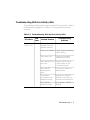
Seven Basic Network Rules. . . . . . . . . . . . . . . . . . . . . . . . 2-3
LAN Product Equivalent Distances . . . . . . . . . . . . . . . . . . 2-6
Maximum Link Distance on Twisted Pair. . . . . . . . . . . . . 2-10
Troubleshooting With the Port Status LEDs . . . . . . . . . . . 4-2
Troubleshooting With the Port Activity LEDs. . . . . . . . . . . 4-5
ONline Ethernet 10BASE-T Module User’s Guide ix
How to Use This Guide
The ONline™ Ethernet 10BASE-T Module User’s Guide describes the
features, indicators, and installation procedures for the ONline Ethernet
10BASE-T Module. Information on troubleshooting and diagnostics is
included for verifying operation. This guide also contains a configuration
section which will be helpful when you plan your network configuration.
Audience
This guide is intended for the following people at your site:
❑
Network manager or administrator
❑
Hardware installer
ONline Ethernet 10BASE-T Module User’s Guide xi
Structure of This Guide
This guide contains the following chapters:
Chapter 1, Introduction –Introduces the principal features of the ONline
Ethernet 10BASE-T Module and provides views and descriptions of the front
panel and the dip switches on the module.
Chapter 2, Designing and Expanding the Network – Shows and
explains examples of possible network configurations using the ONline
System Concentrator and the ONline Ethernet 10BASE-T Module. These
examples include both shielded and unshielded twisted pair configurations.
Chapter 3, Installing and Operating the Module – Provides illustrated
procedures for installing the 10BASE-T Module into the ONline System
Concentrator.
Chapter 4, Troubleshooting –Provides help in isolating and correcting
problems that may arise during the installation process and during normal
operation.
Appendix A, Specifications – Provides electrical, environmental, and
mechanical specifications, as well as other information for the module.
Appendix B, Technical Support – Lists the various methods for
contacting the 3Com technical support organization and for accessing
other product support services.
Index
xii ONline Ethernet 10BASE-T Module User’s Guide
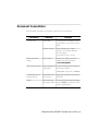
Document Conventions
The following document conventions are used in this manual:
Convention
Courier text
Indicates
Example
User input
In the Agent Information Form,
enter MIS in the New Contact
field.
System output
After pressing the Apply
button, the system displays
the message
Transmitting data.
Bold command
string
Path names
Before you begin, read the
readme.txt file located in
/usr/snm/agents.
Italic text in braces
User-substituted
identifiers
Use the following command to
show port details:
SHOW PORT {slot.all} VERBOSE
Capitalized text in
plain brackets
Keyboard entry
by the user
Type your password and press
[ENTER].
Italics
Text emphasis,
document titles
Ensure that you press the Apply
button after you add the new
search parameters.
ONline Ethernet 10BASE-T Module User’s Guide xiii
Convention
Note:
Indicates
A Note. The
information is
important
Example
Note: Use STP lobe
cables for your system.
Caution: A Caution. A
condition may
damage
software or
hardware
Caution: Do not put
your installation
diskettes on a
magnetic surface.
This may damage the
diskettes.
Warning: A Warning. A
condition may
threaten
personal safety
Warning: Wear eye
protection when
performing these
maintenance
procedures.
Related Documents
This section provides information on suppo rting documentation, including:
❑
3Com Documents
❑
Reference Documents
xiv ONline Ethernet 10BASE-T Module User’s Guide
3Com Documents
The following documents provide additional information on 3Com
products:
17-Slot ONline System Concentrator Installation and Operation
Guide – Explains how to install, operate, and manage the 3Com ONline
17-Slot System Concentrator (Models 5017C-LS and 5017C with load
sharing).
6-Slot ONline System Concentrator Installation and Operation
Guide – Explains how to install, operate, and manage the 3Com ONline
6-Slot System Concentrator.
ONline Ethernet Management Module Installation and Operation Guide –
Describes how to install the ONline Ethernet Network Management
Module in the ONline System Concentrator and explains the LEDs on the
module faceplate. This guide also provides instructions for connecting a
terminal to the module and describes the management commands
necessary to perform management tasks on the concentrator and on
remote devices.
ONline Management Commands Guide – Provides an alphabetized
reference resource describing all ONline management commands.
For a complete list of 3Com documents, contact your 3Com representative.
Reference Documents
The following documents supply related background information:
Case, J., Fedor, M., Scoffstall, M., and J. Davin, The Simple Network
Management Protocol, RFC 1157, University of Tennessee at Knoxville,
Performance Systems International and the MIT Laboratory for Computer
Science, May 1990.
Rose, M., and K. McCloghrie, Structure and Identification of
Management Information for TCP/IP-based Internets, RFC 1155,
Performance Systems International and Hughes LAN Systems, May 1990.
ONline Ethernet 10BASE-T Module User’s Guide xv
1
Introduction
This chapter describes the features, indicators, and dip switch settings on
the ONline™ Ethernet 10BASE-T Module.
The ONline Ethernet 10BASE-T Module
The ONline™ Ethernet 10BASE-T Module is an eight-port IEEE 802.3
repeater module that complies with the 10BASE-T standard. This module
works with the 3Com ONline System Concentrator using both unshielded
and shielded twisted pair wiring. The ONline 10BASE-T Module provides the
following features and benefits:
❑
supports up to 150 meter link distances on 22 gauge wire, up to 125
meters on 24 gauge wire, and up to 100 meters on 26 gauge wire
❑
supports up to 200 meter link distance on IBM Type 1 cabling
❑
complies fully with the 10BASE-T standard
❑
features “hot swap” capability so that you can install or remove the
module without having to power down the concentrator
The 10BASE-T Module works with both unshielded and shielded twisted
pair wire. A single module can support any mix of shielded and unshielded
twisted pair connections. For example, ports 1, 2, and 6 can be unshielded
Introduction 1 - 1
twisted pair connections while ports 3, 4, 5, and 7 are shielded twisted pair
connections.
In addition to complying with the 10BASE-T standard, each port provides
support for features that are beyond the scope of the 10BASE-T standard:
❑
supports shielded twisted pair cable
❑
allows Low Squelch level (which significantly increases achievable link
distances)
❑
allows Link Integrity to be disabled (which allows connection to some
equipment which does not conform to the 10BASE-T standard)
Before installing the Ethernet 10BASE-T Module, read the ONline System
Concentrator Installation and Operation Guide.
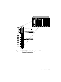
Indicators
The 10BASE-T Module has eight Activity and eight Status LEDs on the front
panel that indicate the state of each port on the module. Figure 1-1 shows
the locations of these indicators and Table 1-1 describes how to read them.
1 - 2 ONline Ethernet 10BASE-T Module User’s Guide
Figure 1-1. 10BASE-T Module Faceplate and ONline
System Concentrator
Introduction 1 - 3
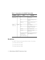
Table 1-1. Interpretation of the 10BASE-T Module LEDs
LED Name
Color
Activity
(Ports 1-8)
yellow
Status
(Ports 1-8)
green
State
Indicates
Off
No packets are received on
the segment.
On
Constant activity on the
segment.
Blinking
Normal activity on the
segment.
Off
Port disabled.
On
Port enabled and Link
Integrity is functional.
1 blink
Link Integrity error.
2 blinks
Jabber error or port
partitioning.
Timed blinks (LED
is on for 10
seconds, blinks
off for 400 msecs)
Link Integrity disabled for
this active port.
Dip Switches
The 10BASE-T Module has three dip switches located on the module:
❑
8-switch dip switch (SW1)
❑
4-switch dip switch (SW3)
❑
8-switch dip switch (SW6)
1 - 4 ONline Ethernet 10BASE-T Module User’s Guide
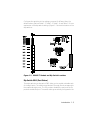
Configure the switches to the settings you want if different than the
default values. (Refer to Table 1-2, Table 1-3, Table 1-4, and Table 1-5 for an
explanation of the dip switch settings.) Figure 1-2 shows the location of the
dip switches.
Figure 1-2. 10BASE-T Module and Dip Switch Locations
Dip Switch SW1 (Port Status)
The eight switches on dip switch SW1 allow you to enable or disable each
of the eight ports. The switches are labeled 1 through 8 and correspond to
the respective eight ports. The Off position disables the port and the On
position enables the port. The switch settings are initially configured in the
Introduction 1 - 5
On position, therefore, all ports are initially enabled. Table 1-2 describes the
settings and functions for switches 1 through 8.
Table 1-2. Dip Switch SW1 Settings and Interpretations
Switch
1-8
Function
Enable/disable port
Factory
Default
enable
Switch Setting
Off
On
disable
enable
If you have an ONline Ethernet Network Management Module installed in
your concentrator, you can remotely override these switch settings. Refer to
the ONline Ethernet Network Management Module Installation and
Operation Guide for information on remotely managing the ports.
Dip Switch SW3 (Crossover Mode, Channel Select, Squelch)
The four switches on dip switch SW3 allow you to:
❑
set port 8 to uncrossed mode
❑
select a channel for the module
❑
set the Squelch level to high (normal) or low (sensitive)
The switches are labeled 1 through 4 and the settings affect all eight ports.
Switch 1 allows you to enable or disable crossover mode for port 8. The
channel is initially configured for channel 1 (default) and Squelch level is
initially configured for high (default). The following sections explain the
crossover, channel selection, and Squelch mode.
If you have an ONline Ethernet Network Management Module installed in
your concentrator, you can remotely override these switch settings.
1 - 6 ONline Ethernet 10BASE-T Module User’s Guide
Table 1-3 explains crossover mode and squelch mode switch settings and
the sections following the table explain these features in more detail. The
channel selection switches are discussed in Table 1-4.
Table 1-3. Dip Switch SW3 Settings for Switches 1 and 4
Factory
Default
Switch Setting
Off
On
Switch
Function
1
Enable/disable
crossover mode for
port 8 only
enable
disable
(uncrossed)
enable
(crossed)
4
Squelch mode
high
low
high
Crossover Mode Switch
All eight ports on the 10BASE-T Module are internally crossed over as per
10BASE-T standard. This enables the 10BASE-T Module to be connected to a
10BASE-T Transceiver. Port 8, however, can be uncrossed using the
crossover mode switch to connect the 10BASE-T Module directly to another
10BASE-T Module without the need for an external crossover adapter. One
port must be crossed over and the other port (port 8) must be uncrossed
when connecting a 10BASE-T Module to another 10BASE-T Module. If both
ports are crossed, you must use an external crossover adapter to provide a
proper connection.
The Off position disables crossover mode (uncrosses) and the On position
enables crossover mode (default), therefore, port eight is initially crossed
over.
Squelch Mode Switch
The Squelch mode switch allows you to set the Squelch level to high
(normal) or low (sensitive). The On position sets the Squelch level to high
(default). The High Squelch level conforms to the proposed 10BASE-T
standard. In general, 3Com recommends using High Squelch.
Introduction 1 - 7
The Off position sets the Squelch level to low. When the Squelch level is set
to low, the ports are able to receive weaker signals. Note that Low Squelch
mode does not conform to the 10BASE-T standard. If you change the
module's Squelch level to low, you must change the 10BASE-T Transceiver
Squelch level to low also. Refer to the ONline Ethernet 10BASE-T
Transceiver Installation Guide for information on setting the transceiver
Squelch level.
On unshielded twisted pair cable, setting the Squelch level to low increases
the achievable link distance by approximately 25% to 50%, but with the
added risk of losing packets to impulse noise. Do not use Low Squelch
mode if your network should experience too many illegally short packets
(runts). This problem will occur if there is significant external noise around
the link.
Setting the Squelch level to low in conjunction with shielded twisted pair
wiring increases the achievable link distance without sacrificing noise
immunity. Thus, there is no real drawback in using Low Squelch on shielded
twisted pair.
To gain the extended link distance achieved by using Low Squelch mode,
you must use qualified data grade shielded twisted pair cable or qualified
high performance unshielded cable. IBM Type 1 shielded cable (with an
appropriate RJ45 to Type 1 connector), among others, meets this
requirement. If you are unsure of the grade of twisted pair cable to use, set
the Squelch level to high, or call 3Com for a list of qualified cables to use in
extended distance applications.
Channel Select Switch Settings
The ONline Ethernet 10BASE-T Module is equipped with the technology to
work with the ONline System Concentrator's unique TriChannel™
architecture. This feature allows you to assign the module to any of three
channels (or none) on the ONline System Concentrator backplane. Refer to
Chapter 1 in the ONline System Concentrator Installation and Operation
Guide for a complete discussion of ONline's TriChannel architecture.
The channel select switch settings (switches 2 and 3) on dip switch SW3 let
you select a channel. Switches 2 and 3 are factory set to On, therefore, the
1 - 8 ONline Ethernet 10BASE-T Module User’s Guide
10BASE-T Module is initially configured to channel 1. To reconfigure the
module to a different channel, refer to the information in Table 1-4.
Table 1-4. Dip Switch SW3 Settings and Interpretations for
Switches 2 and 3
Switch Setting
Switch 2
Switch 3
Channel Selection
On
On
1 (default)
On
Off
2
Off
On
3
Off
Off
Isolated (module
operates independent of
any channel)
If you have an ONline Ethernet Network Management Module installed in
your concentrator, you can remotely override these switch settings.
Dip Switch SW6 (Link Integrity)
The eight switches on dip switch SW6 allow you to enable or disable Link
Integrity for each port. The switches are labeled 1 through 8 and
correspond to the eight ports. The On position enables Link Integrity for
each port (default) and the Off position disables Link Integrity for each
port. The switch settings are initially configured in the On position,
therefore, all eight ports have Link Integrity enabled, as per the 10BASE-T
standard.
In general, you should enable Link Integrity. To conform to the 10BASE-T
standard, for example, a connection requires Link Integrity to be enabled.
You must disable Link Integrity to connect to older equipment which does
not conform to the 10BASE-T standard. Link Integrity must either be
enabled at both ends of the link or disabled at both ends or the module will
report a Link Integrity error.
Introduction 1 - 9
If you enable a port and disable Link Integrity, the Status LED is on for 10
seconds and blinks off for 400 msecs to indicate that Link Integrity is
disabled.
Table 1-5 lists the settings and functions for switches 1 through 8.
Table 1-5. Dip Switch SW6 Settings and Interpretations
Switch
1-8
Function
Enable/disable link integrity
Factory
Default
enable
Switch Setting
Off
On
disable
enable
If you have an ONline Ethernet Network Management Module installed in
your Concentrator, you can remotely override these switch settings.
Related Features
The following sections describe functions which allow you to:
❑
check the module's channel assignment and LED functionality
❑
remotely manage the 10BASE-T Module
LED and Channel Verification
The ONline Controller Module is equipped with an LED/Channel Check
button on the front panel. The LED/Channel Check button has two
functions: it causes all LEDs in all modules in the concentrator to light and it
causes each module to identify the channel to which it is assigned. When
you activate this button, it causes all module LEDs to light for
approximately five seconds. Any LED that does not light is defective.
After the five seconds elapse, the diagnostic continues with a channel
check of all modules. This channel check causes each module's Status LEDs
to blink a number of times corresponding to the channel to which it is
1 - 10 ONline Ethernet 10BASE-T Module User’s Guide
assigned. The channel check sequence repeats five times. Table 1-6 explains
the channel check codes.
Table 1-6. Channel Check Codes
LED State
Channel Configuration
1 Blink
Module is configured for channel 1
2 Blinks
Module is configured for channel 2
3 Blinks
Module is configured for channel 3
Off
Isolated (module operates independent of any
channel)
The LED/Channel Check button and the Controller Module are explained in
more detail in the ONline Controller Module Installation Guide.
The ONline Ethernet Network Management Module
The ONline Network Management Module provides remote network
management capabilities for the ONline System Concentrator and its
modules. The Management Module can also remotely override the
following dip switch settings of the 10BASE-T Module:
❑
enable/disable each port
(SET PORT 6.5 MODE ENABLE)
❑
enable/disable Link Integrity for each port
(SET PORT 3.2 LINK_INTEGRITY ENABLE)
❑
set Squelch to high level or low level per port
(SET PORT 5.1 SQUELCH LOW)
❑
enable/disable crossover mode for port 8
(SET MODULE 5 CROSSOVER DISABLE)
Introduction 1 - 11
❑
change channel selection (per module)
(SET MODULE 4 CHANNEL 2)
The ONline Ethernet Management Module allows you to set redundancy
between the ports. Refer to Redundant Links in Chapter 2 for an example
of setting redundancy between concentrators using 10BASE-T Modules.
Refer to the ONline Ethernet Network Management Module Installation
and Operation Guide for additional information on the Network
Management features.
1 - 12 ONline Ethernet 10BASE-T Module User’s Guide
2
Designing and
Expanding the Network
This appendix contains configuration information that will help you to
design your network. Install all equipment using only approved cables for
proper operation. Refer to Appendix A in the Twisted Pair Connectors and
Cables section for information on twisted pair connector and cable
requirements.
This appendix describes how to configure your network with the ONline
System Concentrator and the ONline Ethernet 10BASE-T Module. It also
provides examples of alternative network cabling structures and rules for
configuring Ethernet networks. There are five sections:
❑
Network Diameter Calculations: General Rules
❑
Fiber Backbone, Twisted Pair To-The-Desk
❑
Twisted Pair Backbone, Twisted Pair To-The-Desk
❑
Redundant Links
❑
Patch Panels
Designing and Expanding the Network 2 - 1
Understanding the General Rules
As part of your network design, it is important to consider your network
size. For instance, is the network (end-to-end) 100 meters, 1000 meters,
4000 meters, or more? What are your plans for expansion? Your answers
play a role in how you configure your network. For example, once the
network expands beyond a certain size, you need to add a bridge or other
internetworking device.
This section describes general rules for configuring an Ethernet network
using fiber as the backbone medium. It also provides rules to ensure that
your network configuration conforms to distance limitations imposed by
Ethernet and networking equipment.
This section includes:
❑
Basic Network Rules
❑
LAN Equivalence
Basic Network Rules
This section outlines the basic network rules and 3Com recommendations
for these rules. For more hardware-specific information on the 10-Port
module, refer to Appendix A.
2 - 2 ONline Ethernet 10BASE-T Module User’s Guide
Table 2-1 outlines the seven basic rules to keep in mind when you construct
your network.
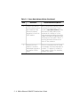
Table 2-1. Seven Basic Network Rules
Rule
1
Definition
Recommendations/Notes
If possible, use
10BASE-FB as the
backbone medium.
Use 62.5 micron cable to conform
with the IEEE 10BASE-F and
upcoming ANSI FDDI standards.
Use ST-type connectors.
2
Wire the backbone in
a star topology to
isolate faults.
Make sure to lay extra fiber cables.
The extra cost is small and you will
find you need them as your network
grows.
The star topology conforms to FDDI
wiring as well -- just make sure to
run at least two fiber strands to
every backbone connection.
3
The maximum Fiber
Ethernet network
diameter is 4200
meters of fiber cable.
The 4200 meters is the maximum
distance between any two
transceivers on the network.
The 4200 meters does not include
the transceiver cable (that is, drop or
patch cable) that connects a device
with an external transceiver.
Transceiver cables can extend up to
50 meters. Thus, total network
diameter can be as much as 4300
meters (4200 m + 2 * 50 m)
between any two nodes.
Designing and Expanding the Network 2 - 3
Table 2-1. Seven Basic Network Rules (Continued)
Rule
Definition
Recommendations/Notes
4
Certain LAN devices
on the network shrink
the maximum Fiber
Ethernet network
diameter to less than
4200 meters.
Many LAN products delay the signal
that goes through them. This is
known as equivalent distance. Every
microsecond delay reduces the
maximum link distance. In fact,
every microsecond delay shrinks the
network diameter by approximately
200 meters of fiber cable. Table 2-2
lists the Equivalent Distances for
other 3Com products.
5
Assume that one
meter of coaxial or
twisted pair is equal to
one meter of fiber
cable.
This is a conservative rule of thumb.
For example, the actual equivalence
is about 1.1 meters of coaxial for
every meter of fiber. For simplicity,
assume one meter.
2 - 4 ONline Ethernet 10BASE-T Module User’s Guide
Table 2-1. Seven Basic Network Rules (Continued)
Rule
Definition
Recommendations/Notes
6
The fiber link distances
must not exceed the
limits imposed by the
optical power budget.
In general, on 62.5 micron cable,
you can go up to 4000 meters
point-to-point using the ONcore or
ONline Fiber Modules. If you have
poor quality cable or cross many
patch panels, you may have to
sacrifice some distance.
Some older Ethernet fiber optic
products are less powerful than
ONcore Fiber Module optics. So
when connecting to these products,
remember that the least powerful
device determines the maximum
point-to-point distance.
7
When in doubt, use a
bridge.
If you are not certain if you have
exceeded allowable network
distances, use a bridge to extend
the network.
Designing and Expanding the Network 2 - 5
LAN Equivalence
LAN equivalence is the sum of both the incoming and outgoing module
port signals. Different modules, however, have different equivalent
distances. Table 2-2 lists the LAN product equivalent distances.
Table 2-2. LAN Product Equivalent Distances
LAN Product
ONcore Ethernet 10-Port 10BASE-FB Module
Incoming signal to fiber port
Equivalent
Distance (meters)
190
140
Outgoing signal from fiber port
50
ONcore Ethernet 10BASE-T Module
585
Incoming signal to TP port
420
Outgoing signal from TP port
165
ONline Ethernet 10BASE-T Modules
585
Incoming signal to TP port
420
Outgoing signal from TP port
165
ONline Ethernet Fiber or 10BASE-FB Modules
Incoming signal to fiber port
Outgoing signal from fiber port
190
140
50
ONline Ethernet FOIRL Module
560
Incoming signal to fiber port
330
Outgoing signal from fiber port
230
ONline Ethernet Transceiver Module
0
10BASE-FB Star Coupler (8 or 14 port) 26
2 - 6 ONline Ethernet 10BASE-T Module User’s Guide
180
Table 2-2. LAN Product Equivalent Distances (Continued)
LAN Product
Equivalent
Distance (meters)
ONline Ethernet BNC Module
900
Incoming signal to BNC port
450
Outgoing signal from BNC port
450
ONline Ethernet Repeater Module
800
Incoming signal to AUI port
600
Outgoing signal from AUI port
200
IEEE Repeater
800
Fiber Backbone, Twisted Pair To-The-Desk
When you configure a network with unshielded or shielded twisted pair
cabling to-the-desk and fiber for the backbone, there are only three
additional rules you need to be aware of:
❑
There can be no more than eight 10BASE-T Modules (5108M-TP) in
the path between any two transceivers due to Ethernet's
four-repeater rule (each 10BASE-T Module counts as a 1/2 repeater).
You must add a bridge if you have more than eight 10BASE-T
Modules serially connected.
❑
There is an equivalent fiber distance for the ONline Fiber Modules
(see Rule 4). The equivalent is:
–
140 meters for signals that externally enter a Fiber Module
port
–
50 meters for signals that internally enter a Fiber Module
via the ONline Concentrator backplane
Designing and Expanding the Network 2 - 7
❑
There is an equivalent fiber distance for the 10BASE-T Modules (see
Rule 4). The equivalence is:
–
420 meters for signals that externally enter a 10BASE-T
Module port
–
165 meters for signals that internally enter a 10BASE-T
Module via the ONline Concentrator backplane
Thus, for every pair of 10BASE-T Modules that a signal goes through, there
is a fiber equivalent distance of 585 meters (420 m + 165 m = 585 m). This
is also true if a signal makes a roundtrip through a single 10BASE-T Module,
i.e., enters a 10BASE-T port externally and exits through another port on
the same 10BASE-T Module. This counts as 585 meters of fiber equivalent
distance, and as a full repeater.
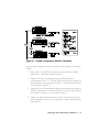
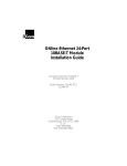
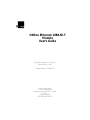
Fiber Backbone, Twisted Pair To-The-Desk Example
In the sample configuration shown in Figure 2-1, we determine if the
transceivers are within legal Ethernet limits. This example is applicable to
both unshielded and shielded twisted pair cables. Note that 22 gauge
unshielded twisted pair cable is used to connect 10BASE-T Transceivers to
the 10BASE-T Modules in the concentrators.
The first step is to identify the two transceivers that are likely to be the
greatest fiber equivalent distance apart. In this case, they are 10BASE-T
Transceivers A and B.
2 - 8 ONline Ethernet 10BASE-T Module User’s Guide
.
Figure 2-1. Sample Configuration Distance Calculation
Use the following steps to determine whether your network configuration
is legal:
1. Begin with 4.2 km (4200 m) since this is the maximum network
diameter for a pure fiber network (Rule 3).
2. Subtract 100 m for the signal exiting the Fiber Modules in
concentrators A and C (2 * 50) and 280 m for the signal entering the
Fiber Modules in concentrators C and B (2 * 140) as explained in Rule
4 and defined in Table 2-2.
3. Subtract 420 m of fiber equivalent distance for the signal entering the
10BASE-T Module in concentrator A and 165 m for the signal exiting
the 10BASE-T Module in concentrator B (Rule 4).
4. Subtract all cable lengths between the two transceivers and if the
result is greater than zero, the configuration is within legal Ethernet
limits (Rule 5).
Designing and Expanding the Network 2 - 9
For the configuration shown in Figure 2-1 to work, the fiber equivalent
distance between transceiver A and transceiver B must be less than 4200
meters. As you can see in the calculation, there are still 1510 meters left for
expansion in this configuration.
Be aware that the link from a 10BASE-T Module to a 10BASE-T Transceiver
should not exceed the distances as defined in Table 2-3. In this example,
the link cannot exceed 150 meters, using the 10BASE-T standard High
Squelch mode and 22 gauge wire.
Table 2-3. Maximum Link Distance on Twisted Pair
Cable Gauge
Unshielded Twisted Pair:
10BASE-T
Supports Link Distances Up To:
High Squelch
Low Squelch
22 (.6mm)
150m
200m
24 (.5mm)
125m
150m
Shielded Twisted Pair:
IBM Type 1
22 (.6mm)
High Squelch
200m
Low Squelch
300m
In areas of low noise, the Squelch level can be lowered to accept weaker
signals. (Low Squelch does not conform to the 10BASE-T standard.) This
allows the acceptable link distance to increase to 200 meters. The 10BASE-T
standard limits link distance to approximately 200 meters (equivalent to
1 µsec of delay) on unshielded twisted pair.
10BASE-T signaling can also be used on shielded twisted pair even though
the standard does not include shielded twisted pair in its specification.
Since external noise does not affect signals on shielded twisted pair, there is
no restriction in using the Low Squelch level. Using Low Squelch on
shielded twisted pair allows link distances of up to 300 meters.
Nevertheless, 3Com recommends that you always use the High Squelch
setting except in situations where the link distance exceeds 200 meters.
2 - 10 ONline Ethernet 10BASE-T Module User’s Guide
Twisted Pair Backbone, Twisted Pair To-The-Desk
In constructing a twisted pair backbone, one additional configuration rule
must be considered:
❑
There can be no more than eight 10BASE-T Modules in the path
between any two transceivers due to the Ethernet four-repeater
rule (each 10BASE-T Module counts as a 1/2 repeater). You must
add a bridge if you have more than eight 10BASE-T Modules
serially connected.
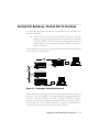
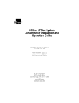
The configuration in Figure 2-2 illustrates a possible unshielded twisted pair
network using 22 gauge cable.
Figure 2-2. Unshielded Twisted Pair Network
Note that when connecting two concentrators with twisted pair cable, use
port 8 on one of the 10BASE-T Modules and disable crossover mode for
that port. This allows a direct connection to another 10BASE-T Module
without the need for an intervening adapter. (Refer to Dip Switch SW3
(Crossover Mode, Channel Select, Squelch) in Chapter 1 for information on
crossover mode and the crossover mode switch setting.)
Designing and Expanding the Network 2 - 11
While there is no fiber in this configuration, the fiber equivalent distance
can be calculated as follows:
Total link distance: 150 m + 100 m + 100 m + 50 m + 20 m = 420 m
Total equivalent distance of 10BASE-T Modules:
4 * 420 m + 4 * 165 m = 2340 m
(signal externally enters four 10BASE-T Modules: 4 * 420 m)
(signal enters four 10BASE-T Modules from the backplane: 4 * 165 m)
Total equivalent distance: 420 m + 2340 m = 2760 m
Since the total equivalent distance (2760 m) is less than 4200 meters, this is
a legitimate configuration.
Note that if shielded twisted pair cabling is used, each link in the network
could run up to 300 meters using Low Squelch (refer to Dip Switch SW3
(Crossover Mode, Channel Select, Squelch) in Chapter 1 for information on
Squelch levels and the Squelch dip switch setting). Low Squelch is
acceptable for all shielded twisted pair applications since external noise is
not a problem.
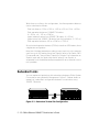
Redundant Links
You can implement twisted pair link redundancy between ONline System
Concentrators using Network Management. Figure 2-3 below shows an
example of a redundant configuration between concentrators using
10BASE-T Modules.
Figure 2-3. Redundant Twisted Pair Configuration
2 - 12 ONline Ethernet 10BASE-T Module User’s Guide
To set redundancy between two 10BASE-T Modules, connect two links
between the modules. The redundant link must be connected to a port on
the same 10BASE-T Module as the primary link. Use a crossover adapter
between each link unless you choose to uncross port 8 on one of the
modules to make the connection. Refer to Chapter 1 for information on
using crossover mode. Then use the SET PORT <slot.port> MODE
REDUNDANT <slot.port> command to specify which port is the primary link
and which is the backup link.
Note: If the 10BASE-T Modules are powered down, and then
brought back up without the Ethernet Management
Module present, a network loop could occur. To prevent a
potential failure, 3Com advises that you disable the Port
Enable dip switch setting for the backup port on one of the
10BASE-T Modules.
Once redundancy is configured, a switchover will occur under three
conditions: a link failure; port partition; or a jabber condition. The
switchover occurs when the primary link fails. (Note that in the unlikely
event of a partial break in the link, a switchover may not occur. In this
situation, use Network Management to manually switch over the ports.)
Once the switchover occurs, and the primary link becomes operational, a
switch-over back to the primary link happens automatically if the cause of
the original switchover was a link failure. If a jabber condition causes the
switchover, the link will not automatically switch back to the primary once
the problem is resolved. In this case, use Network Management to
manually switch back to the primary link.
Refer to the ONline Ethernet Network Management Module Installation
and Operation Guide for information on setting redundancy between
10BASE-T Module ports.
Designing and Expanding the Network 2 - 13
Patch Panels
Patch panels weaken signals, thereby reducing achievable link distances.
3Com includes the use of one patch panel in the 150 meter link distance
calculation. However, each additional patch panel in the link reduces the
150 meter link distance by approximately 10 meters.
In the example in Figure 2-2, if two patch panels were used between the
top right PC and the top right concentrator, the link distance of 150 meters
would have to be shortened to 140 meters. This is because the maximum
allowable link distance on 22 gauge wire using 10BASE-T signaling with two
intervening patch panels is 150 meters minus approximately 10 meters.
Note that a patch panel installed between the bottom right PC and the
bottom left concentrator would not affect the link since it is only 20 meters.
2 - 14 ONline Ethernet 10BASE-T Module User’s Guide
3
Installing and
Operating the Module
This chapter describes the precautionary, unpacking, and installation
procedures for the Ethernet 10BASE-T Module.
Precautionary Procedures
Electrostatic discharge (ESD) can damage static-sensitive devices on circuit
boards. Follow these precautions when you handle the 10BASE-T Module.
❑
Do not remove the board from its anti-static shielding bag until you
are ready to inspect it.
❑
Handle the board by the faceplate.
Use proper grounding techniques when you install the 10BASE-T Module.
These techniques include using a foot strap and grounded mat or wearing
a grounded static discharge wrist strap. An alternate method is to touch
the grounded rack or other source of ground just before you handle the
module.
Installing and Operating the Module 3 - 1
Unpacking Procedures
Use the following procedure when unpacking your 10BASE-T Module.
1. Verify that the 10BASE-T Module is the correct model by matching
the model number listed on the side of the shipping carton to the
model number you ordered (5108M-TP).
Note that the product model number printed on the shipping box
differs from the model number on the product. The model number
on the shipping box contains the prefix ’3C9’.
2. Remove the 10BASE-T Module from the shipping carton.
3. Remove the module from the anti-static shielding bag and inspect it
for damage. Always handle the 10BASE-T Module by the faceplate
being careful not to touch the components.
If the module appears to be damaged, replace it in the anti-static
shielding bag, return it to the shipping carton, and contact your local
supplier.
3Com suggests you keep the shipping carton and anti-static shielding bag
in which your module was shipped in case you later want to repackage the
module for storage or shipment.
We also suggest that you record the serial number of your 10BASE-T
Module. We have provided a log for this and other information specific to
your modules under the Slot Usage Chart in Appendix B of the ONline
System Concentrator Installation and Operation Guide.
Installation Procedures
You do not need to power down the ONline System Concentrator to install
the 10BASE-T Module. You can insert the module while the concentrator is
operating (called a hot insertion). Follow the steps below to install the
10BASE-T Module.
3 - 2 ONline Ethernet 10BASE-T Module User’s Guide
1. Set the dip switches on the board to the settings you want, if
different than the default values. (Refer to Table 1-2, Table 1-3,
Table 1-4, and Table 1-5 for an explanation of the dip switch settings.)
2. Locate a blank slot in the concentrator. If there is no blank slot, you
must remove a blank panel on the concentrator to expose a slot for
the 10BASE-T Module.
3. Insert the module into the board guides at the top and bottom of the
slot and slide it into the concentrator. Make sure the connector is well
seated into the backplane of the concentrator.
Figure 3-1 shows the installation of the 10BASE-T Module.
Figure 3-1. Installing a 10BASE-T Module
Installing and Operating the Module 3 - 3
4. Fasten the spring-loaded screws on the front of the 10BASE-T Module
face-plate to the concentrator with your fingers (do not overtighten).
5. Attach the twisted pair cable to the port on the front of the 10BASE-T
Module as shown in Figure 3-2. Then attach the other end of the
cable to another 10BASE-T Module, a 10BASE-T Transceiver, or a
10BASE-T Adapter Card.
Figure 3-2 shows a cable attached to the 10BASE-T Module.
Figure 3-2. 10BASE-T Module Cable Connection
3 - 4 ONline Ethernet 10BASE-T Module User’s Guide
4
Troubleshooting
This chapter describes troubleshooting procedures for the ONline Ethernet
10BASE-T Module. Information on troubleshooting will assist you in
verifying operation. Typical fault conditions are addressed in this chapter.
Troubleshooting
Diagnostic features are covered in Table 1-1 on page 1-4. Table 4-1 and
Table 4-2 in this chapter cover fault conditions and troubleshooting
suggestions for the 10BASE-T Module. This chapter is divided into the
following parts:
❑
Troubleshooting With the Port Status LEDs
❑
Troubleshooting With the Activity LEDs
❑
Technical Assistance
Troubleshooting 4 - 1
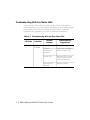
Troubleshooting With the Status LEDs
A blinking Port Status indicator may be a sign that the port detects a
potential problem. Once a port detects a problem, you can further analyze
the problem by counting the number of blinks. Table 4-1 provides
troubleshooting suggestions for each of the blinking sequences.
Table 4-1. Troubleshooting With the Port Status LEDs
LED State
Indication
Off
Port
Disabled
Possible
Problem
Troubleshooting
Suggestions
Port disabled
Enable port.
10BASE-T
Module not
powered
Check the Controller
Module Power LEDs.
Broken LED
Press the LED/Channel
Check button on the
Controller Module.
Bad 10BASE-T
Module
Replace module.
4 - 2 ONline Ethernet 10BASE-T Module User’s Guide
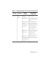
Table 4-1. Troubleshooting With the Port Status LEDs (Continued)
LED State
Indication
1 Blink
Link
Integrity
Error
Possible
Problem
Troubleshooting
Suggestions
Cable not
connected
Connect cable.
Cable broken
Check cable with cable
tester. Repair or replace
cable.
Cable too long
Try a shorter cable.
Remote
connection has
Link Integrity
disabled
Enable Link Integrity at
remote connection or if
the remote link does not
have Link Integrity,
disable Link Integrity at
local connection.
Weak or no
signal - link
distance too
long
Change Squelch level
from high to low (low
setting does not
conform to the
10BASE-T standard).
Bad port
Try another port.
Device attached
to transceiver at
other end is not
powered on
This is not a problem.
Troubleshooting 4 - 3
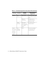
Table 4-1. Troubleshooting With the Port Status LEDs (Continued)
LED State
Indication
2 Blinks
Port
Partitioning
Timed
Blinks (LED
is on for 10
seconds,
blinks off
for 400
msecs)
Possible
Problem
Troubleshooting
Suggestions
Faulty cable
Check cable with cable
tester. Repair or replace
cable.
Network
overloaded
Reassign users to
another channel to
balance the load.
Jabber
condition
Transceiver
attached to the
port is jabbering
or has DTE
jabber
Try another port or
replace module.
Link
Integrity
Disabled
None
This is not a problem.
You may want Link
Integrity disabled.
4 - 4 ONline Ethernet 10BASE-T Module User’s Guide
Troubleshooting With the Activity LEDs
There may be situations where a port's Activity LED may not light. Use the
troubleshooting suggestions in Table 4-2 to help isolate why this has
occurred.
Table 4-2. Troubleshooting With the Port Activity LEDs
LED Name
Activity
(Ports 1 - 8)
LED
State
Off
Possible Problem
Troubleshooting
Solutions
There is no traffic
received from the
segment (normal)
None.
The port is disabled
Check the port enable dip
switch setting.
The power is off
Check the Controller
Module Power LEDs.
The Activity LED has
burnt out
Press the LED/Channel
Check button on the
Controller Module.
The 10BASE-T
Module port is
faulty
Connect the cable to a
different port.
The module
connection to the
backplane is bad
Reinsert the 10BASE-T
Module. If this fails, try
another concentrator slot.
The 10BASE-T
Module is faulty
Try a different 10BASE-T
Module.
Troubleshooting 4 - 5
Technical Assistance
You can receive assistance for installing and troubleshooting the 10BASE-T
Module by calling either your 3Com reseller or 3Com Technical Support. Be
prepared to supply a representative with the following information:
❑
Description of the problem
❑
Steps you have taken to try and correct the problem
❑
Type and software version of the ONline network management
module being used
❑
Version of software installed on your 10BASE-T Module
❑
Status of the front panel LEDs
❑
Configuration of your concentrator
(you may find it helpful to refer to the Slot Usage Chart in Appendix B
of the ONline System Concentrator Installation and Operation Guide
for a record of this information)
Reber to Appendix B for instructions on contacting Technical Support for
your product.
4 - 6 ONline Ethernet 10BASE-T Module User’s Guide
A
Specifications
ONline Ethernet 10BASE-T Module Specifications
This appendix lists specifications for the 10BASE-T Module. There are five
subsections:
❑
Electrical Specifications
❑
Environmental Specifications
❑
Mechanical Specifications
❑
General Specifications
❑
Twisted Pair Connectors and Cables
Electrical Specifications
Backplane Interface: 96-pin edge connector, compatible with the 3Com
ONline System Concentrators.
Power Requirements: 1.75 A for 5V
Fuse: 4.0 Amps Fast blow
Watts: 8.75
Specifications A - 1
Environmental Specifications
Operating Temperature: 0° to 50° C (32° to 122° F)
Storage Temperature: -30° to 65° C (-22° to 149° F)
Humidity: less than 95%, non-condensing
BTU/hr: 30
Mechanical Specifications
Dimensions: 1.0" W x 10.25" L x 8.5" H
(2.54 cm x 26.04 cm x 21.6 cm)
Weight: 1.25 lb. (0.57 kg.)
General Specifications
Data Rate: 10 Mbps (million bits per second)
Data modulation: Manchester
Diagnostic modulation: Link Integrity pulse
Collision detection: 100% deterministic
Maximum number of nodes: 1024
Configuration rules: supports IEEE 802.3 controllers and IEEE 802.3
repeaters
Jabber Protection: 6.5 milliseconds
Port Connectors: Shielded 8-pin modular telephone jack, compatible with
an unshielded connector
Cabling: 22, 24, or 26 AWG unshielded or shielded twisted pair cable
Cable differential impedance: 85 ohms to 150 ohms over 1 to 16 MHz band
A - 2 ONline Ethernet 10BASE-T Module User’s Guide
Cable propagation velocity: >.585c
Host Interface: 3Com ONline System Concentrator bus interface standard
Installation Attachment: Two thumbscrews on the mounting bracket
Twisted Pair Connectors and Cables
There are many types of cables and connectors that you can use to link
your 10BASE-T Module to your network. These cables and connectors are
explained in the following sections. Use this information to ensure that the
cables and connecting hardware meet requirements. For proper operation,
use only approved cables when you install all equipment. This section is
divided into the following parts:
❑
Twisted Pair Connectors
❑
Twisted Pair Cables
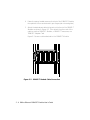
Twisted Pair Connectors
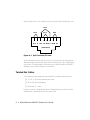
The IEEE 802.3 10BASE-T standard for pin-outs must be used. The following
cable standard must be used. 10BASE-T uses 2 pairs of wire: pins 1 & 2 and
pins 3 & 6. If the pairs are not configured this way, the connection will not
work properly. Datagrade cable should have the following pin pairings:
❑
pins 4 and 5 are pair 1
❑
pins 3 and 6 are pair 2
❑
pins 1 and 2 are pair 3
❑
pins 7 and 8 are pair 4
Specifications A - 3
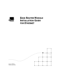
Refer to Figure A-1 for an example of this connector and the cable pin-outs.
Pair 2
Pair 3
Pair 1
1
2
W-G
G
3
4
5
Pair4
6
W-O BL W-BL O
7
8
W-BR BR
Jack Positions
Figure A-1. RJ45 Connector Pin-outs
Some installations may have 50-pin Telco connectors at the wiring closet.
We recommend using a patch panel that converts from 50-pin to RJ45-type
connectors. This allows direct connection to the ONline Ethernet 10BASE-T
Module in your ONline System Concentrator.
Twisted Pair Cables
The cables that are supported must meet the following qualifications:
❑
22, 24, or 26 gauge twisted pair cable
❑
80 to 150 ohm impedance
❑
minimum of 2 pairs
Usually, a pair on a twisted pair cable is designated by a solid color wire
twisted with a striped wire with the same color.
A - 4 ONline Ethernet 10BASE-T Module User’s Guide
Connecting Twisted Pair Cables
We recommend that you connect cables first at the active concentrator
location, and connect transceivers second. Refer to the ONline System
Concentrator Installation and Operation Guide for more information about
the ONline System Concentrator connections.
Specifications A - 5
B
Technical Support
3Com provides easy access to technical support information through a
variety of services. This appendix describes the following services:
❑
On-line Technical Support
❑
Support from Your Network Supplier
❑
Support from 3Com
❑
Returning Products for Repair
❑
Accessing the 3Com MIB
❑
3Com Technical Publications
On-line Technical Support
3Com offers worldwide product support through the following on-line
systems:
❑
Email Technical Service
❑
World Wide Web Site
Technical Support B - 1
Email Technical Support
You can contact the Integrated Systems Division (formerly Chipcom) on the
Internet for technical support using the e-mail address
[email protected].
World Wide Web Site
You can access the latest networking information on the 3Com World
Wide Web site by entering our URL into your Internet browser:
http://www.3Com.com/
This service features news and information about 3Com products,
customer service and support, the 3Com latest news releases, selected
articles from 3TECH™ , the 3Com award-winning technical journal, and
more.
You can contact the Integrated Systems Division on the World Wide Web
by entering our URL into your Internet browser:
http://www.chipcom.com/
There are links between both WWW pages to view information from all
3Com divisions.
Support from Your Network Supplier
If additional assistance is required, contact your network supplier. Many
suppliers are authorized 3Com service partners who are qualified to provide
a variety of services, including network planning, installation, hardware
maintenance, application training, and support services.
B - 2 ONline Ethernet 10BASE-T Module User’s Guide
When you contact your network supplier for assistance, have the following
information ready:
❑
Diagnostic error messages
❑
A list of system hardware and software, including revision levels
❑
Details about recent configuration changes, if applicable
If you are unable to contact your network supplier, see the following
section on how to contact 3Com.
Support from 3Com
If you are unable to receive support from your network supplier, technical
support contracts are available from 3Com.
For direct access to customer service for Integrated Systems Division
products in:
❑
U.S.A. and Canada - call (800) 724-2447
❑
Asia Pacific - call (508) 787-5151
❑
Europe - Refer to the table below. For European countries not listed,
call 31 30 60 299 00.
Country
Telephone Number
Country
Telephone Number
Belgium
0800 71429
Netherlands
06 0227788
Denmark
800 17309
Norway
800 11376
Finland
0800 113153
Spain
900 983125
France
05 917959
Sweden
020 795482
Germany
0130 821502
U.K.
0800 966197
Ireland
1 800 553117
U.S.
800 876-3266
Italy
1678 79489
Technical Support B - 3
For access to customer service for all 3Com products, call (800) 876-3266.
You can also contact the Integrated Systems Division (ISD) on the Internet
by using the e-mail address [email protected].
Returning Products for Repair
A product sent directly to 3Com for repair must first be assigned a Return
Materials Authorization (RMA) number. A product sent to 3Com without
an RMA number will be returned to the sender unopened, at the sender’s
expense.
To obtain an RMA number for Integrated Systems Division products
(formerly Chipcom), use the following numbers.
Country
Telephone Number
Fax Number
U.S. and Canada
(800) 724-2447
(508) 787-3400
Europe
(44) (1442) 275860
No Fax
Asia Pacific
(508) 787-5296
(508) 787-3400
Accessing the 3Com MIB
The 3Com Management Information Base (MIB) for the Integrated Systems
Division describes commands that enable you to manage 3Com
SNMP-based products. The MIB is available over the Internet on an
anonymous FTP server. Updates to these MIBs are released as new 3Com
products are introduced.
To access Internet versions:
1. FTP to ftp.chipcom.com (151.104.9.65).
2. Enter the login name anonymous.
B - 4 ONline Ethernet 10BASE-T Module User’s Guide
3. Enter your full Internet e-mail address as the password
(for example, [email protected]).
4. Change to the mib or schema directory using the cd /pub/mibs or
cd /pub/mibs/schemas command.
5. To view the 3Com MIB, OID, or schema entries, enter the dir
command.
❑
To pause the display, press [CTRL-S].
❑
To continue the display, press [CTRL-Q].
6. Copy the MIB, OID, or schema files to your current directory using the
appropriate command (for example, get chipcom.mib).
7. To exit the FTP session, invoke the quit command.
3Com Technical Publications
If you have comments or questions on 3Com Integrated Systems Division
Technical Publications documents, please contact the Technical Publications
group by FAX (508) 229-1551.
Technical Support B - 5
Index
Numerics
D
3Com Bulletin Board Service (3ComBBS), B-3
Dip Switch Settings
Channel Select, 1-8, 1-9
Crossover Mode, 1-6, 1-7
Link Integrity, 1-9, 1-10
Port Status, 1-5
Squelch Mode, 1-7, 1-8
Dip Switches, 1-4
A
Audience of Manual, xi
B
Backbone
Fiber Medium, 2-2
bulletin board service, B-3
C
Cable Types
Shielded Twisted Pair, 1-1
Unshielded Twisted Pair, 1-1
Cabling
Connectors, A-3, A-4
Fiber Backbone, 2-7, 2-8, 2-10
Redundant Links, 2-13
Twisted Pair Backbone, 2-11
Twisted Pair Connections, 2-10
Wire Types, A-4
Configuration Rules
Fiber Backbone, 2-9
Configuration Rules
Fiber Backbone, 2-7, 2-8
General, 2-2, 2-3, 2-5
Twisted Pair Backbone, 2-11, 2-12
F
FCC notice, ii
Features, 1-1, 1-2
Fiber Link Distances, 2-5
Front Panel Indicators
Activity LEDs, 1-2, 1-4
Status Indicators, 1-2
Status LEDs, 1-4
I
Installation
Cabling, 3-4
Installing The Module, 3-3, 3-4
L
LAN Product Equivalent Distances, 2-6
Link Distances
Configuration Rules, 1-1
Index 1
M
U
MIB, B-4
Unshielded Twisted Pair, 2-8, 2-10, 2-11
N
V
network supplier support, B-2
VDE compliance, ii
O
W
ONline Controller Module, 1-10
ONline Ethernet Management Module, 1-11,
Wire Types, 1-1
1-12
on-line technical services, B-1
P
Patch Panels, 2-14
R
Redundancy, 2-13
returning products for repair, B-4
S
Shielded Twisted Pair, 2-10, 2-12
SNMP Commands, B-4
Star Topology, 2-3
T
Technical Assistance, 4-6
Technical Support, 4-6, B-1
Troubleshooting
Port Activity LEDs, 4-5
Port Status LEDs, 4-1, 4-3, 4-4
Technical Assistance, 4-6
Twisted Pair
Cables, A-4, A-5
Connections, A-5
Connectors, A-3, A-4
2 Index