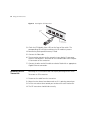
1
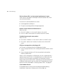
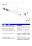
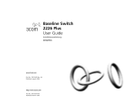
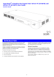
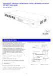
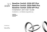
3Com® Unified Gigabit Wireless
PoE Switch 24
Quick Start Guide
Kurzanleitung
3CRUS2475
Copyright ® 2006 3Com Corporation. All rights reserved.
www.3Com.com
Part Number 10015246 Rev. AA
Published September 2006
About this Guide
This guide is intended for use by those responsible for installing and
setting up network equipment; consequently, it assumes a basic working
knowledge of LANs (local area networks) and WLANs (wireless local area
networks).
Diese Anleitung ist fur die Benutzung durch Netzwerkadministratoren
vorgesehen, die fur die Installation und das einstellen von
Netzwerkkomponenten verantwortlich sind; sie setzt Erfahrung bei der
Arbeit mit LANs (Local Area Networks) und WLANs ( Wireless Local Area
Networks) voranus.
3
Get the latest documentation
and software for your
3Com switch
Thank you for purchasing a 3Com® Unified Gigabit Wireless PoE
Switch 24. As part of our commitment to help you get the most out of
your 3Com network equipment, we offer updated documentation and
software on our website.
In addition to this Quick Start Guide, a detailed User Guide and a
Command Line Interface Guide are also available on the 3Com website.
To obtain the most up-to-date user documentation and operating
software for the 3Com Unified Switch 24, point your web browser to:
www.3Com.com and select the “Support and Registration” link.
Please note that you must register your 3Com switch to receive software
upgrades. To register, point your web browser to eSupport.3Com.com.
4
Get the latest documentation and software for your 3Com switch
5
Contents
About this Guide
2
Get the latest documentation and software
for your 3Com switch 3
1
Introducing the 3Com Unified Gigabit
Wireless PoE Switch 24 7
Overview of the Unified Gigabit Wireless PoE Switch 24
Unified Switching 9
Wired Features 10
Power over Ethernet (PoE) Features 10
Wireless Features 10
2
Installing the 3Com Unified Switch 24
Checking the Package Contents 11
Choosing a Suitable Location 11
Aufstellen des Switch 12
Free-Standing Installation 12
Placing Units On Top of Each Other
Rack-Mount Installation 13
Montagesatz Anweisungen 14
Supplying Power 15
Stromversorgung 15
Checking for Correct Operation 16
3
9
11
13
Connecting to the 3Com Unified Switch 24
Before you begin 17
Connecting your computer to the switch 17
Using the setup wizard 18
Preparing the wireless network 20
Activating the Managed Access Points 21
17
6
4
Preparing the Managed Access Points
Preparing the 7760 Access Point
Preparing the 8760 Access Point
Resetting Access Points 26
5
23
24
25
Upgrade your Switch to the Latest Software
27
Loading Software into the Switch 27
Running a New Software Image 28
6
Restoring the Factory Default Settings
7
Changing the Password 30
8
Using SFP Transceivers
31
Approved SFP Transceivers 31
Inserting and using an SFP Transceiver
Removing an SFP Transceiver 32
9
10
Troubleshooting
29
31
33
Technical Information
35
Related Standards 35
Environmental 35
Physical 36
Electrical 36
11
Obtaining Support for your 3Com Product
Register Your Product to Gain Service Benefits 37
Solve Problems Online 37
Purchase Extended Warranty and Professional Services
Access Software Downloads 38
Contact Us 38
Telephone Technical Support and Repair 39
38
37
7
1
Introducing the
3Com Unified Gigabit
Wireless PoE Switch 24
Figure 1 Front and Rear Views of the Unified Switch 24
1&2
3 56 7
8
4
10
9
11
Table 1 Features of the Unified Switch 24
Reference
Description
1
10/100/1000 Mbps Network Ports (1–24): These autonegotiating ports determine the speed and
duplex mode based on the connected device. Each port supports automatic MDI/MDIX detection and
can be connected to a 10BASE-T, 100BASE-T, or 1000BASE-T device.
2
LED Port Status Indicators: Each Network Port has a corresponding status indicator (1 to 24) that
shows the status of the port’s network connection or PoE status (depending on the LED Status Select
button).
Port Speed
■
Green steady: 1000 Mbps link is present.
■
Green flashing: 1000 Mbps traffic is present.
■
Amber steady: 10/100 Mbps link is present.
■
Amber flashing: 10/100 Mbps traffic is present.
■
Off: Link is not present
PoE Status
■
Green steady: PoE Power is being delivered to the port
■
Off: No power is being delivered.
8
Introducing the 3Com Unified Gigabit Wireless PoE Switch 24
Table 1 Features of the Unified Switch 24 (continued)
Reference
Description
3
LED Status Select Button: This button sets the function of the Port LED indicators. When the button
is in the out position, the port LEDs show the port speed (see #2 above). When the button is pressed
in, the port LEDs show the PoE status.
4
SFP Module Slots (21–24): The four Small Form Factor Pluggable (SFP) transceiver slots allow you to
install an SFP transceiver (purchased separately). These ports support fiber Gigabit Ethernet short-wave
(SX) and long-wave (LX) SFP transceivers in any combination.
When an SFP module is installed in a slot and is active, the associated RJ-45 port (21 to 24) of the
same number is disabled.
5
SFP Module Status Indicator: The four SFP status LED indicators show the state of the SFP module
ports (21 to 24; see #4).
■
Green: An SFP fiber module is present.
■
Off: No fiber module is present.
When an SFP module is present, the fiber port activity is indicated by the corresponding LED over the
RJ-45 port (21 to 24):
6
■
Green steady: Fiber link is present.
■
Green flashing: Fiber link traffic is present.
■
Off: Link is not present
Fan Indicator: Shows the status of the internal fans.
Green steady: All fans are functioning properly.
Amber steady: The switch is too hot.
Amber flashing: One or more fans have failed
7
System Indicator: Shows the overall status of the switch.
■
Green steady: The switch is powered-up and operating normally.
■
Green flashing: The switch is undergoing self test, initialization, or downloading.
■
Amber steady: The switch has detected a hardware malfunction such as temperature, fan, or
voltage.
■
Off: No power. The switch is off.
8
Console Port: Allows you to connect a terminal and perform out-of-band management. The default
communications settings are 19200 bps, 8 data bits, no Parity, 1 stop bit.
9
Reset Button: Use the reset button to restore the switch to its factory defaults. See “Restoring the
Factory Default Settings” on page 29.
10
AC Power Input: Accepts 100–240 Vac, 50/60 Hz input power. The switch automatically adjusts to
the input voltage.
11
Feet: These are self-adhesive pads. You do not need to install them if you are rack-mounting the
switch.
Overview of the Unified Gigabit Wireless PoE Switch 24
9
WARNING: The Network Ports are shielded RJ-45 data sockets. They
cannot be used as standard traditional telephone sockets, or to connect
the unit to a traditional PBX or public telephone network. Connect only
RJ-45 data connectors, network telephony systems, or network
telephones to these sockets.
Either shielded or unshielded data cables with shielded or unshielded
jacks can be connected to these data sockets.
AVERTISSEMENT: Points d’accès RJ-45. Ceux-ci sont protégés par des
prises de données. Ils ne peuvent pas être utilisés comme prises de
téléphone conventionnelles standard, ni pour la connection de l’unité à
un réseau téléphonique central privé ou public. Raccorder seulement
connecteurs de données RJ-45, systèmes de réseaux de téléphonie ou
téléphones de réseaux à ces prises.
Il est possible de raccorder des câbles protégés ou non protégés avec des
jacks protégés ou non protégés à ces prises de données.
WARNHINWEIS: RJ-45-Porte. Diese Porte sind geschützte
Datensteckdosen. Sie dürfen weder wie normale traditionelle
Telefonsteckdosen noch für die Verbindung der Einheit mit einem
traditionellem privatem oder öffentlichem Telefonnetzwerk gebraucht
werden. Nur RJ-45-Datenanscluße, Telefonnetzsysteme or Netztelefone
an diese Steckdosen anschließen.
Entweder geschützte oder ungeschützte Buchsen dürfen an diese
Datensteckdosen angeschlossen werden.
Overview of the
Unified Gigabit
Wireless PoE
Switch 24
Unified Switching
The 3Com® Unified Gigabit Wireless PoE Switch 24 is a versatile,
easy-to-use unified switch. It is shipped ready for use, and no
configuration is necessary for operation as a basic Layer 2 Gigabit PoE
switch. Additional features such as wireless can be configured easily using
the Web-based user interface and setup wizard. Support for PoE and
voice auto-prioritization makes the Unified Switch 24 a perfect starting
point for IP telephony solutions.
A unified switch is an all-in-one, fully-managed Ethernet switch
combining gigabit, wireless, and PoE connectivity in a single platform.
The Unified Switch 24 supports both wired Ethernet switching and
centralized control for up to 24 wireless access points.
10 Introducing the 3Com Unified Gigabit Wireless PoE Switch 24
Wired Features
The switch has 24 shielded RJ-45, 10/100/1000 Mbps auto-negotiating
ports and four Small Form Factor Pluggable (SFP) transceiver slots on the
front panel.
The four SFP ports support fiber Gigabit Ethernet short-wave (SX) and
long-wave (LX) SFP transceivers in any combination. This offers you the
flexibility of using SFP transceivers to provide connectivity between the
switch and a 1000 Mbps core network.
When an SFP port is in operation, the corresponding 10/100/1000BASE-T
port (21 to 24) is disabled.
Power over Ethernet
(PoE) Features
Wireless Features
The switch can provide Power over Ethernet (PoE) to 802.3af compliant
devices over a Category 5 or better Ethernet cable. The switch can supply
up to 15.4 Watts of PoE to each of the 24 gigabit ports simultaneously.
PoE (802.3af) is a self-configuring protocol. When you plug an 802.3af
device into one of the gigabit ports on the switch, the switch will supply
the required power to the device.
The 3Com Unified Switch 24 provides centralized control for up to 24
3Com 7760 or 8760 Access Points. Key wireless features include:
■
Enterprise-grade WPA2/AES encryption
■
802.1X authentication
■
Centralized control for wireless security profiles
■
Fast roaming
■
Rogue AP detection and mitigation
■
Multiple SSIDs per radio
■
Traffic prioritization
■
Load balancing
11
2
Checking the
Package Contents
Installing the 3Com Unified
Switch 24
The Unified Switch 24 package includes the following items:
■
One 3Com Unified Gigabit Wireless PoE Switch 24 unit
■
One power cord
■
Four standard height, self-adhesive rubber pads
■
One mounting kit
■
One warranty flyer and one safety flyer
■
This Quick Start Guide
If any of the above items are damaged or missing, please contact your
network supplier immediately.
WARNING: Before installing this switch, please read the safety flyer
included with the unit.
GEFAHR: Lesen Sie bitte vor Installation des Switch das diesem Gerät
beiliegende Sicherheitsblatt durch.
Choosing a Suitable
Location
The switch can be free-standing (see “Free-Standing Installation” on
page 12), or it can be mounted in a 19-inch equipment rack using the
supplied mounting kit (see “Rack-Mount Installation” on page 13). When
deciding where to position the switch, ensure that:
■
It is accessible and cables can be connected easily.
■
Cabling is away from sources of electrical noise. These include elevator
shafts, microwave ovens, and air-conditioning units. Electromagnetic
fields can interfere with the signals on copper cabling and introduce
errors, and, consequently, slow down your network.
■
Water or moisture cannot enter the case of the unit.
12 Installing the 3Com Unified Switch 24
■
Air flow around the unit and through the vents on the side of the case
is not restricted. 3Com recommends that you provide a minimum of
25 mm (1 in.) clearance.
■
The air is as free of dust as possible.
■
Temperature operating limits are not likely to be exceeded. 3Com
recommends that you install the switch in a clean, air conditioned
environment.
When installing network equipment, it is always good practice to wear an
antistatic wrist strap that is connected to a ground point. If one is not
available, try to keep in contact with a grounded rack and avoid touching
the unit's ports and connectors. Static discharge can cause reliability
problems in your equipment.
Aufstellen des
Switch
Free-Standing
Installation
Bei der Entscheidung wo Sie den Switch positionieren, stellen Sie sicher
das:
■
Der Switch zugänglich ist und die Kabel leicht angeschlossen werden
können.
■
Die Kabel nicht in der nähe von elektrischen Störquellen befinden. Das
schließt Aufzugsschächte, Mikrowellen und Klimaanlagen ein.
Elektromagnetische Felder können die Signale in den Kupferleitungen
stören, und Fehler verursachen, was die Verlangsamung Ihres
Netzwerkes zur Folge haben kann.
■
Weder Wasser noch Feuchtigkeit in das Gehäuse eindringen kann.
■
Die Luftzirkulation um den Switch und durch die Öffnungen des
Gehäuses nicht behindert wird. 3Com empfiehlt das Sie 25mm (1
Inch) Zwischenraum sicherstellen.
■
Die Luft so frei wie möglich von Staub ist.
■
Es unwahrscheinlich ist das die Betriebstemperatur überschritten wird.
3Com empfiehlt das Sie den Switch in einer sauberen, klimatisierten
Umgebung installieren.
Place the switch on a stable, flat surface where it is not likely to be
disturbed. Do not place objects on top of the switch or on top of a stack
of switches. When locating the unit, you should take note of the
guidelines given in “Choosing a Suitable Location” on page 11.
Rack-Mount Installation 13
If you are installing the switch in a free-standing stack with other 3Com
equipment, arrange the smaller units above the larger ones. Do not have
a free-standing stack of more than four units.
Placing Units On Top
of Each Other
If the switch units are free-standing, up to four units can be placed one
on top of the other. If you are mixing a variety of 3Com equipment, the
smaller units must be positioned at the top.
If you are placing switch units one on top of the other, you must use the
self-adhesive rubber pads supplied. Apply the pads to the underside of
each switch, sticking one in the marked area at each corner.
Rack-Mount
Installation
The switch is one rack-unit (1U, or 1.75 in.) high and will fit in a standard
19-inch equipment rack. The supplied mounting kit includes two
mounting brackets and four screws. When rack-mounting the unit, you
should take note of the guidelines given in “Choosing a Suitable
Location” on page 11.
CAUTION: Disconnect all cables from the unit before continuing.
Remove the self-adhesive pads from the underside of unit, if already
fitted.
1 Place the unit on a hard, flat surface with the front facing towards you.
2 Position a mounting bracket over the mounting holes on one side of the
unit. Refer to Figure 2 “Attaching Rack-Mount Hardware” on page 14.
3 Insert the screws supplied in the mounting kit and fully tighten with a
suitable screwdriver.
4 Repeat the two previous steps for the other side of the unit.
5 Insert the unit into the 19-inch rack and secure with suitable screws (not
provided).
6 Reconnect all cables.
14 Installing the 3Com Unified Switch 24
Figure 2 Attaching Rack-Mount Hardware
Montagesatz
Anweisungen
Der Switch wird mit zwei Halterungen und vier Schrauben geliefert. Diese
werde für den Einbau in einen Baugruppenträger benutzt. Bei der
Montage der Baugruppe beachten Sie die Anweisungen aus “Aufstellen
des Switch“.
Der Switch ist eine Baueinheit hoch und passt in einen Standard 19'' (Zoll)
Baugruppenträger.
ACHTUNG: Entfernen Sie alle Kabel, bevor Sie fortfahren. Entfernen Sie
die selbstklebenden Polster (Füße) von der Unterseite der Baugruppe, falls
diese bereits angebracht sind.
1 Plazieren Sie die Baugruppe aufrecht auf einer harten, ebenen Fläche mit
der Vorderseite zu Ihnen.
2 Ordnen Sie eine der Halterungen über den Löchern an der Seite der
Baugruppe an.
3 Stecken Sie zwei der mitgelieferten Schrauben in die Löcher und drehen
Sie diese mit einem geeigneten Schraubendreher fest.
4 Widerholen Sie letzten beiden Schritte auf der anderen Seite der
Baugruppe.
5 Führen Sie die Baugruppe in den 19" (Zoll) Baugruppenträger ein und
sichern sie die Baugruppe mit geeigneten Schrauben. (Nicht im
Lieferumfang enthalten.)
6 Schließen Sie alle Kabel wieder an.
Supplying Power 15
Supplying Power
Ensure that the power input to your system is clean and free from sags
and surges to avoid unforeseen network outages.
Before powering on the switch, verify that the power cable is securely
connected.
CAUTION: The switch has no On/Off switch; the only method of
connecting or disconnecting main power is by connecting or
disconnecting the power cord.
CAUTION: Connect the switch to a properly grounded electrical outlet
using only the supplied power cord.
1 Plug the power cord into the power socket on the rear panel of the
switch. See page 8 for more information.
2 Plug the other end of the power cord into a properly-grounded outlet.
When the switch is powered on, the System LED lights. If the System LED
does not light, see “Checking for Correct Operation” on page 16 for
more information.
Stromversorgung
Stellen Sie sicher, dass der Stromeingang zum System frei ist und vor
Unter- und Überspannungen geschützt ist.
Bevor Sie den Switch mit Strom versorgen, stellen Sie sicher, dass das
Netzkabel sicher eingesteckt ist.
WARNUNG: Der Switch hat keinen Ein/Aus-Schalter; die einzige
Methode zum Verbinden oder Trennen vom Stromnetz ist es, das
Netzkabel ein- oder auszustecken.
WARNUNG: Verbinden Sie den Switch nur mit dem mitgelieferten
Netzkabel und einem ordnungsgemäß geerdeten Stromanschluss.
1 Stecken Sie das Netzkabel in den Stromanschluss auf der Hinterseite des
Switch. Weitere Informationen finden Sie auf page 8.
2 Stecken Sie das andere Ende des Stromkabels in einen ordnungsgemäß
geerdeten Stromzugang.
Wenn der Switch mit Strom versorgt wird, leuchtet die System-LED.
Wenn die System-LED nicht leuchtet, finden Sie unten weitere
Informationen unter “Checking for Correct Operation” on page 16.
16 Installing the 3Com Unified Switch 24
Checking for
Correct Operation
After you power-on the switch, it automatically performs a power-on
self-test (POST). During the POST, the System LED on the front panel of
the switch flashes green.
When the POST is complete, the System LED turns green. If the System
LED turns amber after the POST, it means that POST failed. Table Table 2
summarizes the possible colors for the System LED after a POST.
Table 2 Possible System LED Colors After a POST
Color
State
Green
The unit is powered on and ready for use.
Amber
Power-on self-test or loopback test failed. This indicates that
there is a hardware malfunction.
Off
The unit is not receiving power:
■
Verify that the power cord is connected correctly, and
then try powering on switch again.
■
If the switch still does not operate, contact your 3Com
network supplier
If POST fails, try the following:
■
Power off the Switch 24 and then power it on again by unplugging
and then plugging in the power cord.
■
Check the System LED and determine if the POST was successfully
completed.
■
Reset the switch to the factory defaults. See “Reset Button” on
page 8.
CAUTION: Resetting the switch to its factory defaults erases all your
settings. You will need to reconfigure the switch after you reset it.
If these do not resolve the issue:
■
Check the 3Com Knowledgebase for a solution. To visit the 3Com
Knowledgebase Web site, start your Web browser, and then enter
http://knowledgebase.3Com.com
■
Contact your 3Com network supplier for assistance.
17
3
Connecting to the 3Com
Unified Switch 24
This section describes how to connect to the 3Com® Unified Switch 24
and interact with the Web-based user interface. The user interface allows
you to control the operation of the switch and configure its features.
Before you begin
Connecting your
computer to the
switch
The following items are required before you can connect to your Unified
Switch 24:
■
A Windows PC with Internet Explorer version 6.0 or greater is required
for using the Web-based user interface
■
A DHCP server is required to use the wireless features of the switch.
The DHCP server is used to assign IP addresses to the managed access
points.
To configure your switch for the first time, you must connect your
computer directly to the switch.
169.254.2.100 = Default IP address
Unified Switch 24
169.254.2.200
PC
Ethernet cable
1 Make sure that the switch is powered on (see “Supplying Power” on
page 15).
2 Connect a network cable from your computer’s Ethernet port to any
Ethernet port on the Unified Switch 24.
18 Connecting to the 3Com Unified Switch 24
CAUTION: Do not connect any network cable to the Console port on the
switch. Connect only to the Ethernet ports.
3 Ensure that your computer is on the same subnet as the switch.
NOTE: The switch’s default IP address is 169.254.2.100.
a If your computer is using static IP addressing, ensure that its address is
within the same subnet as the switch, for example 169.254.2.200.
b If your computer is not using static IP addressing, Windows will
automatically assign an IP address in the correct subnet.
4 Start your Web browser and type the switch’s IP address into the address
bar: http://169.254.2.100.
Using the setup
wizard
The Unified Switch 24 can be configured through its web interface using
either the feature menu items, or by using the Setup Wizard. This section
describes how to use the Setup Wizard to quickly configure your switch
for basic Layer 2 and wireless networking. The wizard guides you through
configuring the system settings, IP settings, wireless settings, and saving
your changes. For complete configuration information, refer to the User
Guide.
1 If you have not done so already, access the switch’s Web user interface by
typing the switch’s IP address into the address bar of your Web browser:
http://169.254.2.100.
2 Log onto the switch by entering the user name and password and
clicking the Login button.
■
The default username is admin.
■
The default password is blank (no entry).
3 Launch the Setup Wizard by clicking the Wizard tab.
A welcome screen is displayed, showing the switch’s current
configuration. You will use the Next and Back buttons to navigate the
wizard and configure your switch.
4 Use the Next button to access the System Setup page. If you want to use
wireless, you must check Master Radio Enable and select the
appropriate Country Code. This setting is used to determine the
allowable radio channels for your access points. The System Name,
Location, and Contact are optional.
Using the setup wizard 19
5 Use the Next button to access the IP Configuration page and choose
either Static or DHCP addressing.
For most installations, 3Com recommends that you configure the switch
with a static IP address. This makes management simpler and more
reliable, as it eliminates the risk of the switch’s IP address changing.
Take a moment to record the IP settings you select.
IP Address:
______________________________
Subnet Mask:
______________________________
Default Gateway: ______________________________
6 Use the Next button to access the Wireless Configuration page. Set the
default SSID and security that will be applied to all your access points.
This allows you to quickly setup a secure wireless network. You can
change these parameters later if you wish. For complete wireless
configuration information, refer to the User Guide.
Take a moment to record the wireless settings you select.
SSID:
______________________________
Security Type: ______________________________
Passphrase:
______________________________
VLAN ID:
______________________________
7 Use the Next button to access the Wizard Summary page. Review your
settings and use the Back button if you wish to make any changes. When
you are satisfied with your settings click the Finish button to complete
the wizard and save your settings.
8 If you have changed the default IP address of the switch, follow these
steps to log onto the switch:
a After you click Finish, click OK to confirm the changed IP address.
b Configure your PC’s IP address to have the same subnet as the switch.
c Log onto the switch again using the new IP address.
9 Select Save Configuration to store your switch settings to the startup
configuration.
10 The switch is now fully configured for basic Layer 2 networking. If you
wish to use the switch’s wireless features, continue with the steps in
“Preparing the wireless network” on page 20.
20 Connecting to the 3Com Unified Switch 24
CAUTION: When you make configuration changes to the switch, you
must select Save Configuration to store your settings to the startup
configuration. If you do not select Save Configuration, any modified
settings will be lost the next time the switch is restarted.
CAUTION: To protect your switch from unauthorized access, you should
change the default password as soon as possible. See “Changing the
Password” on page 35.
Preparing the
wireless network
To use the wireless features of your switch, you must first connect a
DHCP server to the switch. The DHCP server is required to assign IP
address to the managed access points. If you are already using a cable,
DSL, or traditional router to access the Internet, you may use this router’s
DHCP functionality to provide IP addresses to the access points.Refer to
the figure below.
1
Connect DHCP server first
DHCP Server
Unified Switch 24
PC
AP 7760
Wireless Managed
Access Point
AP 8760
Wireless Managed
Access Point
2
Connect access points
after DHCP server
Activating the Managed Access Points 21
To prepare your wireless network follow these steps:
1 Connect the DHCP server to a port on the Unified Switch 24.
Make sure that the DHCP server is on the same IP subnet and is using the
same subnet mask as IP configuration of the switch.
2 Connect the wireless access points to the switch only after you have
connected the DHCP server and it is fully operational.
To prepare the access points, see “Preparing the Managed Access Points”
on page 23.
Activating the
Managed Access
Points
Managed access points must be either directly connected to the switch or
connected using a Layer 2 network to the same subnet as the switch. The
switch and the managed access points must be on the same Layer 2
subnet in order for them to communicate.
To Discover and Activate the managed access points follow these steps:
1 Ensure the access points are converted to managed access points. (Refer
to “Preparing the Managed Access Points” on page 23.)
2 Ensure the access points are connected to the switch.
3 Log in to the Web interface of the switch.
4 Select Device Summary, then click the Wireless tab.
5 In a short time you should see a list of “Discovered Access Points”.
6 Press the Activate button for each access point that you want to be
controlled by your switch. The switch will take several minutes to activate
the access points.
7 When the state has changed to Activated, the wireless network is ready
for use. You can access the wireless network using the SSID and security
parameters you configured in the setup wizard.
NOTE: When an access point is activated on a unified switch, the access
point is imprinted with a special security key (LTK). The LTK is shared
between the unified switch and the access point. An access point that
has been activated by a unified switch will only communicate with that
one switch. If you later wish to activate the access point on a different
unified switch, you must clear the LTK by performing a Short Reset on the
access point as described in “Resetting Access Points” on page 26.
22 Connecting to the 3Com Unified Switch 24
23
4
Preparing the Managed
Access Points
The 3Com® Unified Switch 24 supports these 3Com access points:
■
3Com Wireless 7760 11a/b/g PoE Access Point (3CRWE776075)
■
3Com Wireless 8760 Dual Radio 11a/b/g PoE Access Point
(3CRWE876075)
The AP 7760 and AP 8760 are dual function access points and have two
start-up modes: Stand-alone and Managed. The start-up mode
determines how the access point operates.
Stand-alone mode: The access point operates as an independent
fully-functional standalone device. This is the default operating mode of
the access point.
Managed mode: The access point operates as a device that is
dependent on the 3Com Unified Switch 24 for management and control.
Managed mode is only used if you are operating the 7760 and 8760 with
the 3Com Unified Switch 24.
In order to use the access points with the 3Com Unified Switch 24, you
must first prepare the access points as follows:
1 Ensure the access point Stand-alone firmware is at the minimum required
level.
2 Ensure that a Managed firmware image is present on the access point.
3 Set the access point to Managed mode.
The following sections, “Preparing the 7760 Access Point” and
“Preparing the 8760 Access Point”, describe how to prepare the 3Com
access points for use with your Unified Switch 24.
24 Preparing the Managed Access Points
Preparing the 7760
Access Point
If you are not familiar with accessing the 3Com 7760 Web interface, refer
to the 7760 Access Point Quick Start Guide.
1 Log on to the access point Web interface.
2 Check the serial number on the back of the access point.
If the serial number starts with BA/ or higher, a managed image is already
installed. You can skip steps 3 and 4 and go directly to step 5.
3 Ensure the 7760 Stand-alone firmware version is 1.5.25 or greater.
a View the firmware version on the Management -> Firmware
Upgrade page.
b Upgrade the Stand-alone firmware if required.
Get the latest firmware by visiting www.3Com.com. Select Support &
Downloads then Downloads & Drivers and enter the model
number (3CRWE776075).
c Use the Management -> Firmware Upgrade page and set Image
Type to Stand-alone to load the Stand-alone firmware.
4 If the serial number of your access point is not BA/ or higher, you must
load a Managed firmware image to the access point.
a Get the Managed firmware image by visiting www.3Com.com,
selecting Support & Downloads then Downloads & Drivers and
entering the model number (3CRWE776075).
b On the 7760, use the Management -> Firmware Upgrade page
and set Image Type to Managed to load the Managed firmware.
c Click the Upgrade button.
5 Change the access point Start-up Mode from Stand-alone to Managed
using the System Configuration -> System Properties page.
6 Click the Apply button. The access point will reboot automatically.
7 To make the access point active on your Unified Switch 24, see
“Activating the Managed Access Points” on page 21.
Note: After the access point is in Managed mode, it can no longer be
accessed using WIDMan, HTTP, Telnet, or SNMP. An access point in
Managed mode can only be discovered and managed by the 3Com
Unified Switch 24. To return the access point to the default Stand-alone
mode, refer to “Resetting Access Points” on page 26 of this Quick Start
Guide.
Preparing the 8760 Access Point 25
Preparing the 8760
Access Point
If you are not familiar with accessing the 3Com 8760 Web interface, refer
to the 8760 Access Point Quick Start Guide.
1 Log on to the access point Web interface.
2 Check the serial number on the back of the access point.
If the serial number starts with BA/ or higher, a managed image is already
installed. You can skip steps 3 and 4 and go directly to step 5.
3 Ensure the 8760 Stand-alone firmware version is 2.1.13 or greater.
a View the firmware version on the Advanced Setup -> Status -> AP
Status page.
b Upgrade the Stand-alone firmware if required.
Get the latest firmware by visiting www.3Com.com, selecting
Support & Downloads then Downloads & Drivers and entering
the model number (3CRWE876075).
c Use the Advanced Setup -> Administration page and scroll to the
Firmware Upgrade/Local section to upgrade the Stand-alone
firmware.
4 If the serial number of your access point is not BA/ or higher you must
load a Managed firmware image to the access point.
a Get the Managed firmware image by visiting www.3Com.com,
selecting Support & Downloads then Downloads & Drivers and
entering the model number (3CRWE876075).
b Use the Advanced Setup -> Administration page and scroll to the
Firmware Upgrade/Local section to upgrade the Managed
firmware.
5 Change the access point Start-up Mode from Stand-alone to Managed
using the Advanced Setup -> Administration page and scrolling to the
Start-up Mode section.
6 Click the Change Start-up Mode button.
7 After the Configuration Complete message appears reset the access
point by clicking the Reset button.
8 To make the access point active on your Unified Switch 24, see
“Activating the Managed Access Points” on page 21.
Note: After the access point is in Managed mode, it can no longer be
accessed using WIDMan, HTTP, Telnet, or SNMP. An access point in
26 Preparing the Managed Access Points
Managed mode can only be discovered and managed by the 3Com
Unified Switch 24. To return the access point to the default Stand-alone
mode, refer to “Resetting Access Points” below.
Resetting Access
Points
AP Recovery
To recover an access point that was inadvertently changed to Managed
mode, perform a long reset as described below. The long reset changes
the access point’s start-up mode back to the factory default of
Stand-alone mode. Using a long reset is the only way to return an access
point from Managed mode to Stand-alone mode. To perform a long
reset, during power-up press and hold the Reset button for at least 20
seconds.
Reset Button
The Reset button on the access points can be used to perform two
different types of system reset: a short reset, and a long reset.
Short Reset A short reset deletes the current configuration file and
restores the factory settings. The short reset does not change the start-up
mode of the access point, so if the start-up mode of the access point is in
Stand-alone it will remain in Stand-alone mode. If the start-up mode of
the access point is in Managed it will remain in Managed mode.
To perform a short reset, press and hold the Reset button for at least
5 seconds (but not more than 20 seconds).
Long Reset A long reset changes the start-up mode of the access point
back to the factory default mode of Stand-alone. This is only used if the
access point was inadvertently changed to Managed mode and you want
to return it to Stand-alone mode. A long reset is the only way to return
from Managed mode to Stand-alone mode.
To perform a long reset, press and hold the Reset button for at least 20
seconds.
27
5
Upgrade your Switch to the
Latest Software
This section describes how to upgrade your 3Com® Unified Switch 24 to
the latest software.
The latest software for your switch can be obtained by visiting
www.3Com.com, selecting Support & Downloads then Downloads &
Drivers and entering the model number (3CRUS2475).
To provide enterprise-grade redundancy, the switch maintains two
software images in memory: Image 1 and Image 2. One image is used to
run the switch (“active”), and the other image provides backup
redundancy. You can set which image is running and which is redundant.
Loading Software
into the Switch
This sections describes how to put a new software image into your
Unified Switch 24. To run the new software, see see “Running a New
Software Image” on page 28. The switch software can be loaded using
HTTP or TFTP. HTTP instructions are listed below. For details on TFTP please
refer to the User Guide.
To upgrade the switch software using HTTP:
1 Copy the latest switch software from www.3Com.com to your PC.
2 Expand the downloaded software.
3 Log in to the switch Web interface.
4 Select Administration -> Software Update.
5 Select Download via HTTP.
6 Click Browse and locate the software you previously copied to your PC.
7 Click Apply.
The software will be loaded into the software image location that is not
active.
28 Upgrade your Switch to the Latest Software
Running a New
Software Image
This sections describes how to run software that you have uploaded to
the switch. To put the software image into your switch, see “Loading
Software into the Switch” on page 27.
To run new software, you must set the image to become active after the
switch is reset. The Active Image tab identifies which image is currently
active and which image will be used after the next reset.
To select new software to run:
1 Select Administration -> Software Update, then click the Active
Image tab.
The Active Image field displays the name of the software image
currently in use (either Image 1 or Image 2).
2 Set the Active Image After Reset field to the other software image. For
example, if Active Image displays Image 1, set Active Image After
Reset to Image 2.
3 Reset the switch by selecting Administration -> Reset.
29
6
Restoring the Factory
Default Settings
CAUTION: Resetting the switch to factory defaults will erase all your
settings. You will need to reconfigure all settings.
To reset the switch to factory defaults:
1 Unplug the power cord from the back of the unit.
2 Press and hold the Reset button on the back of the switch.
3 While still pressing the Reset button, plug the power cord into the back
of the unit.
4 Continue pressing the reset button for 10 seconds.
5 Release the Reset button.
The switch is now reset to factory defaults.
30 Changing the Password
7
Changing the Password
To protect your 3Com® Unified Switch 24 from unauthorized access, you
should change the default password as soon as possible.
To change the password:
1 Log onto the switch.
■
The default username is admin.
■
The default password is blank (no entry).
2 Select Administration -> Authentication -> Password Management.
3 Click the Modify tab and enter your new password.
4 Click Apply.
The password has now been changed.
31
8
Using SFP Transceivers
This sections describes how to insert and remove an SFP transceiver from
an SFP slot.
SFP transceivers are hot-insertable and hot-swappable. You can remove
them from and insert them into any SFP port without having to power-off
the switch.
Approved SFP
Transceivers
The following list of approved SFP transceivers is correct at the time of
publication:
■
3CSFP91 SFP (SX)1000BASE-SX SFP transceiver. Use this transceiver to
connect the switch directly to a multimode fiberoptic cable.
■
3CSFP92 SFP (LX)1000BASE-LX SFP transceiver. Use this transceiver to
connect the switch directly to a single-mode fiberoptic cable or to
multimode fiber using a conditioned launch cable.
3Com recommends using only 3Com SFPs on the switch. If you insert an
SFP transceiver that is not supported, the switch will not recognize it.
Inserting and using
an SFP Transceiver
To insert and use an SFP transceiver, follow the procedure described
below.
1 Hold the transceiver so that the fiber connector is toward you and the
product label is visible, as shown in Figure 3. Ensure the wire release lever
is closed (in the upright position).
2 Gently slide the transceiver into the SFP slot until it clicks into place.
CAUTION: SFP transceivers are keyed and can be properly inserted only
one way. If the transceiver does not click when you insert it, remove it,
turn it over, and then re-insert it.
32 Using SFP Transceivers
Figure 3 Inserting the SFP Transceiver
Product
label
Suitable port
on host Switch
3 Check the SFP Module Status LEDs on the front of the switch. The
corresponding LED will light to indicate the SFP module is present.
4 Remove the plastic protective cover, if fitted.
5 Connect the fiber cable.
6 The transceiver connects to the network using a duplex LC connector.
Attach a male duplex LC connector on the network cable into the duplex
LC connector on the transceiver.
7 Connect the other end of the cable to a device fitted with an appropriate
Gigabit Ethernet connection.
Removing an SFP
Transceiver
Removing an SFP transceiver does not require powering-off the switch.
To remove an SFP transceiver:
1 Disconnect the cable from the transceiver.
2 Move the wire release lever downwards until it is pointing toward you.
3 Pull the wire release lever toward you to release the catch mechanism.
4 The SFP transceiver should slide out easily.
33
9
Troubleshooting
For complete troubleshooting information please refer to your User's
Guide or visit 3Com’s World Wide Web site: http://www.3Com.com.
Here are some common problems that can occur.
Forgotten Password
If you forget the password to the Web interface, you will need to reset
the switch to factory defaults. See “Restoring the Factory Default
Settings” on page 29.
A link is connected, but the Port Status LED for the port is off
There is a problem with this connection. Verify that:
■
The device being connected to is powered on and operating correctly.
■
The cable is connected at both ends.
■
The cable is not damaged.
■
If the connection is to a workstation, that the workstation's network
interface is installed and configured correctly.
■
The correct category of cable is being used for the required link speed.
Category 3 cables can be used for 10BASE-T operation only. Category
5 cable is required for 100BASE-TX or 1000BASE-T. 3Com
recommends Category 5e or 6 cables for 1000BASE-T operation.
A fiber cable is connected, but the Module Status LED is off
Verify that:
■
The fiber cable is in good condition.
■
The SFP module is correctly inserted.
■
A 3Com® SFP module is being used. Refer to “Using SFP Transceivers”
on page 31 for details.
■
The equipment at the far end is installed and correctly configured.
34 Troubleshooting
The Port Status LED is on, but network performance is poor
There may be a full-duplex / half-duplex mismatch between the switch
and a connected device.
Ensure that the connected device has either:
■
Auto-negotiation enabled, or
■
The ports are configured for half-duplex operation
Browser cannot find the Unified Switch 24
Make sure that:
■
The PC’s IP address is in the same IP subnet as the switch.
■
The PC’s subnet mask matches the subnet mask of the switch.
Trouble discovering the access points
Make sure that:
■
The switch’s IP address is in the same IP subnet as the DHCP server.
■
The switch’s subnet mask matches the subnet mask of the DHCP
server.
LTK Error message when activating an AP
An LTK error is caused by either of the following situations:
■
You are trying to activate an AP is already activated on another unified
switch.
■
You are trying to activate an AP that was previously activated on
another unified switch.
When an AP is activated on a unified switch, the AP is imprinted with a
special security key (LTK) that is shared between the unified switch and
the AP. An AP that has been activated by a unified switch will only
communicate with that one switch. If you later wish to activate the AP on
a different unified switch, you must clear the LTK by performing a Short
Reset on the AP as described in “Resetting Access Points” on page 26.
If the Problem Persists
If the problem persists refer to the more detailed troubleshooting
information in your User’s Guide or on the 3Com Web site.
35
10
Related Standards
Technical Information
The 3Com® Unified Gigabit Wireless PoE Switch 24 has been designed to
the following standards:
Function
IEEE 802.3 (Ethernet, 10Base-T), IEEE 802.3u (Fast
Ethernet, 100Base-TX), IEEE 802.3ab (Gigabit Ethernet,
1000Base-T) and IEEE 802.3z (Gigabit Ethernet,
1000Base-X), IEEE 802.3x (Flow Control), IEEE 802.1d
1998 (Bridging), IEEE 802.1p (Virtual LAN), IEEE 802.af
(DTE Power)
MAC Address
8192
Safety
UL 60950-1, CSA 22.2 No. 60950-1, EN 60950-1,
IEC 60950-1
EMC Emissions
FCC Part 15 Subpart B Class A, EN 55022 Class A,
ICES-003 Class A, CISPR 22 Class A, VCCI Class A,
EN 61000-3-2, EN 61000-3-3
Immunity
EN 55024, EN 60601-1-2
Environmental
Operating Temperature 0 to 40 °C (32 to 104 °F)
Storage Temperature
–40 to +70 °C (–40 to +158 °F)
Humidity
10 to 95% (non-condensing)
Standard
EN 60068 (IEC 68)
36 Technical Information
Physical
Width
44.0 cm (17.3 in.)
Length
41.5 cm (16.3 in.)
Height
4.4 cm (1.75 in.) or 1U.
Weight
5.9 kg (13.0 lb)
Mounting
Free-standing, or 19 in. rack-mounted using the
supplied mounting kit
Power Inlet
IEC 320
AC Line Frequency
50/60 Hz (±3 Hz)
Input Voltage
100–240 Vac (auto range)
Current Rating
8 Amp (maximum)
Maximum Power
Consumption
465 Watts
Maximum Power
Dissipation
207 BTU/hr
PoE Maximum Output
Power per Port
15.4 watts
Electrical
Power can also be provided by the switch through any
of its 24 Ethernet ports based on the IEEE 802.3af
Power over Ethernet (PoE) specifications. For PoE to
work, the receiving device must be PoE-compliant.
37
11
Obtaining Support for your
3Com Product
3Com offers product registration, case management, and repair services
through eSupport.3Com.com. You must have a user name and password
to access these services, which are described in this appendix.
Register Your
Product to Gain
Service Benefits
To take advantage of warranty and other service benefits, you must first
register your product at:
http://eSupport.3Com.com
3Com eSupport services are based on accounts that are created or that
you are authorized to access.
Solve Problems
Online
3Com offers the following support tool:
■
3Com Knowledgebase — Helps you to troubleshoot 3Com
products. This query-based interactive tool is located at:
http://knowledgebase.3Com.com
It contains thousands of technical solutions written by 3Com support
engineers.
38 Obtaining Support for your 3Com Product
Purchase Extended
Warranty and
Professional
Services
To enhance response times or extend your warranty benefits, you can
purchase value-added services such as 24x7 telephone technical support,
software upgrades, on-site assistance, or advanced hardware
replacement.
Experienced engineers are available to manage your installation with
minimal disruption to your network. Expert assessment and
implementation services are offered to fill resource gaps and ensure the
success of your networking projects. For more information on 3Com
Extended Warranty and Professional Services, see:
http://www.3Com.com
Contact your authorized 3Com reseller or 3Com for additional product
and support information. See the table of access numbers later in this
appendix.
Access Software
Downloads
You are entitled to bug fix / maintenance releases for the version of
software that you initially purchased with your 3Com product. To obtain
access to this software, you need to register your product and then use
the Serial Number as your login. Restricted Software is available at:
http://eSupport.3Com.com
To obtain software releases that follow the software version that you
originally purchased, 3Com recommends that you buy an Express or
Guardian contract, a Software Upgrades contract, or an equivalent
support contract from 3Com or your reseller. Support contracts that
include software upgrades cover feature enhancements, incremental
functionality, and bug fixes, but they do not include software that is
released by 3Com as a separately ordered product. Separately orderable
software releases and licenses are listed in the 3Com Price List and are
available for purchase from your 3Com reseller.
Contact Us
3Com offers telephone, internet, and e-mail access to technical support
and repair services. To access these services for your region, use the
appropriate telephone number, URL, or e-mail address from the table in
the next section.
Contact Us 39
Telephone Technical
Support and Repair
To obtain telephone support as part of your warranty and other service
benefits, you must first register your product at:
http://eSupport.3Com.com
When you contact 3Com for assistance, please have the following
information ready:
■
Product model name, part number, and serial number
■
A list of system hardware and software, including revision level
■
Diagnostic error messages
■
Details about recent configuration changes, if applicable
To send a product directly to 3Com for repair, you must first obtain a
return materials authorization number (RMA). Products sent to 3Com
without authorization numbers clearly marked on the outside of the
package will be returned to the sender unopened, at the sender’s
expense. If your product is registered and under warranty, you can obtain
an RMA number online at http://eSupport.3Com.com. First-time users
must apply for a user name and password.
Telephone numbers are correct at the time of publication. Find a current
directory of 3Com resources by region at:
http://csoweb4.3Com.com/contactus/
Country
Telephone Number
Country
Telephone Number
Philippines
1800 144 10220 or
029003078
800 810 0504
800 616 1463
080 698 0880
00801 444 318
001 800 441 2152
Asia, Pacific Rim — Telephone Technical Support and Repair
Australia
Hong Kong
India
Indonesia
Japan
Malaysia
New Zealand
1800 075 316
2907 0456
000 800 440 1193
001 803 852 9825
03 3507 5984
1800 812 612
0800 450 454
PR of China
Singapore
South. Korea
Taiwan
Thailand
Pakistan Call the U.S. direct by dialing 00 800 01001, then dialing 800 763 6780
Sri Lanka Call the U.S. direct by dialing 02 430 430, then dialing 800 763 6780
Vietnam Call the U.S. direct by dialing 1 201 0288, then dialing 800 763 6780
You can also obtain non-urgent support in this region at this email address [email protected]
Or request a return material authorization number (RMA) by FAX using this number: +61 2 9937 5048, or send an
email at this email address: [email protected]
Europe, Middle East, and Africa — Telephone Technical Support and Repair
From anywhere in these regions not listed below, call: +44 1442 435529
40 Obtaining Support for your 3Com Product
Country
Telephone Number
Country
Telephone Number
Luxembourg
Netherlands
Norway
Poland
Portugal
South Africa
Spain
Sweden
Switzerland
U.K.
800 23625
0800 0227788
800 11376
00800 4411 357
800 831416
0800 995 014
900 938 919
020 795 482
0800 553 072
0800 096 3266
From the following countries, call the appropriate number:
Austria
Belgium
Denmark
Finland
France
Germany
Hungary
Ireland
Israel
Italy
0800 297 468
0800 71429
800 17309
0800 113153
0800 917959
0800 182 1502
06800 12813
1 800 553 117
180 945 3794
800 879489
You can also obtain support in this region using this URL: http://emea.3com.com/support/email.html
You can also obtain non-urgent support in this region at these email addresses:
Technical support and general requests: [email protected]
Return material authorization: [email protected]
Contract requests: [email protected]
Latin America — Telephone Technical Support and Repair
Antigua
Argentina
Aruba
Bahamas
Barbados
Belize
Bermuda
Bonaire
Brazil
Cayman
Chile
Colombia
Costa Rica
Curacao
Ecuador
Dominican Republic
1 800 988 2112
0 810 444 3COM
1 800 998 2112
1 800 998 2112
1 800 998 2112
52 5 201 0010
1 800 998 2112
1 800 998 2112
0800 13 3COM
1 800 998 2112
AT&T +800 998 2112
AT&T +800 998 2112
AT&T +800 998 2112
1 800 998 2112
AT&T +800 998 2112
AT&T +800 998 2112
Guatemala
Haiti
Honduras
Jamaica
Martinique
Mexico
Nicaragua
Panama
Paraguay
Peru
Puerto Rico
Salvador
Trinidad and Tobago
Uruguay
Venezuela
Virgin Islands
AT&T +800 998 2112
57 1 657 0888
AT&T +800 998 2112
1 800 998 2112
571 657 0888
01 800 849CARE
AT&T +800 998 2112
AT&T +800 998 2112
54 11 4894 1888
AT&T +800 998 2112
1 800 998 2112
AT&T +800 998 2112
1 800 998 2112
AT&T +800 998 2112
AT&T +800 998 2112
57 1 657 0888
You can also obtain support in this region in the following ways:
■
Spanish speakers, enter the URL: http://lat.3com.com/lat/support/form.html
■
Portuguese speakers, enter the URL: http://lat.3com.com/br/support/form.html
■
English speakers in Latin America, send e-mail to: [email protected]
US and Canada — Telephone Technical Support and Repair
All locations:
Network Jacks; Wired or Wireless Network Interface Cards:
1 847-262-0070
All other 3Com products:
1 800 876 3266