1
Serial
Number
............
ModeJ and serial
number may be found
at the rear
of the cabinet.
You should
model
record
both
CRRFTSMRHo
and serial number
in a safe place for
future
use.
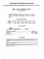
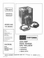
295 AMP
DUAL RANGE
ARC WELDER
CAUTION:
Read
SAFETY
® assembly
iNSTRUCTIONS
® operating
carefully
• repair
Sold by SEARS,
Part No. 61341
ROEBUCK
AND
parts
CO.,
Chicago,
IL
60684
U,S.A.
_
:'_ ' . _ _,
SAFETY
For your own protection,
mcluded nn this manual
safety precautions.
1. PROTECTION
iNSTRUCTiONS
TO OPERATOR
read and observe all instructions
as well as the following
specific
FROM
ELECTRICAL
SHOCK
a. Do not let bare skin or wet clothing come
the following combnnatlons
Electrode and Electrode Holder
of the arc can react with solvent
vapors
phosgene,
a highly
toxic gas, and other
products.
h.
between
Unprotected
specators
must
be kept clear
of the
welding area doe to the harmful
nature of ultra-wolet
and infra-red
arc rays,
fumes and gases
3. FLAMMABLE
Work Clamp
Work
Piece
Metal Work
b,
b
clothing,
the body.
gloves and
shoes
to
Take special care to insulate yourself
from ground
using dry =nsulatuon (such as dry wood} of adequate
s=ze when welding m damp Iocat,ons, on metal floors
or gratings, and in positions
(such as s_tting or lying)
where parts or large areas of your body can be in
contact w_th possible grounds.
e
Connect
use welding
the
electrode
welder
only
power
meeting
the
grounding,
of the National
and local codes
f.
as a cigarette
to
a source
of
C.
including
(ANSI C1)
a,
b
arc
when
or
Always
wear
safety
goggles with
side
shields
complying
with ANSI Z87 1 when Jn a welding area,
or when near slag chipping
operation
c. Wear od free protective
garments,
gloves, heavy shirt, cuffless
trousers
d. Protect
other
non flammable
e
welding
near-by
screening.
personnel
Provide
ddequdte
ventilation
in the welding
area,
particularly
when
welding
on galvanized,
lead or
cadmeum plated steel, and other metal whtch produce
toxic fumes
g
When worktng
above floor
level, protect
from a fall should you get a shock. Never
electrode
cable
Do
weld
not
around
m
any part of your
Iocat=ons
close
yourself
wrap the
body
to
chlorinated
hydrocarbon
vapors
com=ng
from
degreasmg.
cleaning,
or sprawng
operations
The heat of the rays
2
wh,ch hold combustibles
When not welding, place the electrode holder where it
is _nsulated
from
the work
clamp,
work
p=ece, or
work
table.
Accidental
grounding
can
cause
overheating
of the cables and wetder, creating a fire
hazard
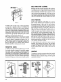
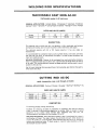
MAINTENANCE
Never apply power to the welder wnth any part of the
"cabinet"
removed.
Position on-off
switch
in "Off"
power
cord
to
the
1
Inspect the power cord and welding cables for cuts
or burns and make sure blades and ground pm on
the plug are stranght
2
Inspect
parts.
3
Inspect electrode
or broken parts
suitable
"On-Off"
sw_tch fever for cracks or broken
holder
law insulators
for cracks
e. Never weld anything
on or to the welder cabinet,
burn through may cause transformer
failure
d
f
on or near containers
b. Before connecting
the welder
receptacle,
check the following
such as leather
and high shoes
w_th
MATERIALS
posltnon
and disconnect
welder
from
the power
supply
before
donng maintenance
work inside the
machine.
Removal
of the welder cabinet should be
done only by a qualifned servnce techmcran
cover plate complytng
with
your eyes and face from
sparks and the rays of the
obserwng open arc weld=rig
Welding
4. PREVENTATIVE
2. EYE AND BODY PROTECTION
Use helmet,
filter,
and
ANSI
Z87 1 to protect
welding
the work cable or clamp to any object
but the work piece or metal work table. Connectnng
to other objects such as budding ground can create a
fire hazard
electrical
Electrode
coating
may be eleetncaUy
conductnveuse welding gloves when ehangnng electrodes.
a
EXPLOSIVE
and
d Never connect
hghter
requ,rements,
Electrical
Code
sparks,
can cause an expiosmn,
even when they have been
cleaned
For =nforn_atcon purchase "Safe Practtces for
Welding
and Cutting
Containers
that
Have Held
Combustrbles"
(A6.0-65}
from the Amerfcan
Welding
Society
2501 Northwest
Seventh St, Mnam_ FJorlda
33125
c. Manntain
the electrode
holder,
work clamp, welding
cable and welding
machine
in good, safe operating
condition.
d. Do not
AND
welding
a. Remove flammable
and explosive
mater_al at least 35
feet from the welding arc to prevent welding sparks
or molten
metal from
starting
a fire. Keep a type
ABC f_r_ extinguisher
within easy reach
Table
80 volts exast between
these parts
when welder is onq I
Wear dry hole-free,
protect and insulate
to form
irritating
as a
For additional
safety information,
purchase copies of
"Practice
for Occupational
and Educational
Eye and
Face Protection"
(ANSI
Z87.1),
"Safety
_n Welding
and Cutting"
(ANSI Z49.1),
and "F_re Protection
in
Use of Welding
and Cutting
Processes" (ANSI'NFPA
No
51B)
from
the Amerncan
Natnonal
Standards
[nstntute,
1430 Broadway,
New York, N Y 10018
READ
AND
OBSERVE
THE
INSTRUCTIONS
APPEARING ON THE WARNING LABELS FOUND ON
THE INSIDE OF THE WELDING HELMET, SELECTOR
PLATE, AND CABINET,
WARNING
_AFTSMRn
--
FOR
REGARD;NG
_HOCK
YOUR
SAFETY
80 VOLT pO'_ENTIAL
AT ELECTRODE
12_ 0_fy for €_c1_ _
_
Pr_ecb0n
a_,_hr_l _nlU_o_ rays from _C _dhng
_ARNIrJG
Pro_e_t
_ou,_lf
and
un_,stalld
thl_ Idbel
_ther_
R_d
and
_U',IES
_rJD GASE_ _arl be _l_r,ge,v_s to _,l_r ne_h_
_pC
RA' g _an 1nitre eves _nd bdrr, ,kin
_LECTRIC
SHOCK,
n r,ll
• _ead
_rd understand
the m=m_fJ_l_r_,
,n,tr_¢tlons
• n_ y_ur enlp_owr
• _fet,
praCtl_eS
• Feep y_ur he_d our _t th_ f_,,_es
• U,e en_o@h vent,lab,on
eqhust
ro keep fu,_e_ and qase, rr_nl
and th_ _ner_l
are_
• Wea_ correct
eye
eor _ml uauy
_,hPn
_m_
lil_S _v_ce
_mpacl
R£GARDING
re
•
3rid
_ tb_ _rc o_ _oth
y_r
ble_th,ng
_one
serI_L_SI_
,
reduce pt01_CllOn--
_
POTENTIAL
u_
_
SHOCK
,
REGARDI_IG
_ ,.
0_
_
CABI¢_ET
_
Inspe_l rr_quenll 7 ,_nd _mm_al_l_
protect,on
_NOT
• See Am=r,_n
p_uonal
Sl_n_rJ
Z49 I
S_fel_
,n
¢,eld, l_ _,1_ (urr,,_g
m,_h,hall
b, the ,_er,c_n
'_eld,nc Society
2501
_
71h St
"1_,_,
FL_r,da
_3125
OSH& S,r_t_
a,lo H_lhh
_ta_cla,_,
?gCFR
_910
_,l_b_e
Tr_rn U _ D_pJrtn,e_l_
_f L_bar
,_asn,_l_n
DC 2O210
O0 NOT _E_O.
E THIS L_BEL
REMOVE THiS L_L
LENS
SHADE NO
FIEGARDFNG
F_ItE
@
WARNING" ARC WELDING CAN BE INJURIOUS TO OPERATOR AND PERSONS IN WORK AREA
READ AND UNDERSTAND
OWNERS MANUAL BEFORE OPERATING
WELDER
FULL ONE YEAR WARRANTY
If
this Craftsman
within
Electrm
Welder
_
EYE _NJU_y
ON CRAFTSMAN
fails to perform
properly,
ELECTRIC
due to a defect
-
WELDER
in material
or workmanship,
one year from the date of purchase, Sears wdl repair It, free of charge
Warranty
throughout
service is available
by simply
returning
the welder
to the nearest Sears store or Serwce
Center
the United States.
Th_s warranty
state.
gives you specific
legal rights, and you
may
also have other rights which
vary from
state to
SEARS, ROEBUCK AND CO
BSC 41-3
SEARS TOWER
CHICAGO. IL 60684
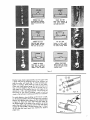
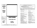
;ELECTOR
LOCKING
KNOB
MATERIAL
LECTRODE
GETTING TO
KNOW YOUR
ARC WELDER
DUAL
RANGE
DIAMETER
OUTLET
GAUGE
JACKS
:TRODE
ELECTRODE
CABLE AND
HOLDER
WELDING
WORK
CABLE
AND
TABLE
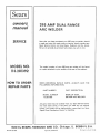
OPERATING
Safety
INSTRUCTIONS
Instructions
to Operator
Warranty
Getting
to Know
Unpacking
Assembly
OFCONTENTS
Your
Welder
and Check m_ Contents
2
• 3
3
4
4
Operating
Controls
6
Operating
Instructions
7
Trouble Shooting
ARC WELD IT YOURSELF
WELDING
REPAIR
MANUAL
ROD SPECIFICATIONS
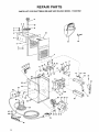
PARTS
1-1
2-1
2=5
3
SPECIFICATIONS
Welding Range ..............
Primary Volts (AC)
Amps Input (Max.) ...................
30 - 295 amps
........
230
60
Fuse Requ=red (Delayed Act=on Type)
Phase .......................
UNPACKING
.........
60
Single
AND
In order
removed
welder
=s sh_pped
complete
to facd=tate packaging, certain
at the factory
and must be
_n one carton
=terns have been
assembled
when
received by the purchaser
Remove all =terns from
the
carton and =dent=fy =tern as shown m the exploded view
,,,4:,:
If'_l
1
WELDER
Etectrode Capacity
Over-all Dimensions
CHECKING
SET-UP I NSTR UCTIONS
Th_s Craftsman
Hertz ..............................
Open C=rcult Volts (Max.) .................
Duty Cycle .....................
2
_'_""'_
4
5
..........
..........
1/16" thre 1/4"
21" x 14'" x 15"
CONTENTS
_llustratton These "Loose Parts" should be accounted
before discarding any packaging matertal
LOOSE
Key
No.
1
2
3
4
5
PARTS
PartName
_r
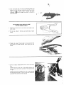
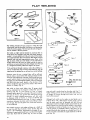
ATTACHING
ELECTRODE
TO
DO NOT
REMOVE
Sbde the
handle
electrode
cable
The electrode
from one end
CABLE
holder and locate the slotted head,
near the rind-point
of the insulating
screw approximately
two terns, or
be shpped off the electrode holder.
THIS
off
SCREW
electrode
assembly
cable
(medluml
HOLDER
ELECTRODE
1. Grasp the electrode
handle locking screw
handle.
Loosen th_s
until the handle can
2.
Screwdriver
through
=s the
COMPLETELY
holder
one
and
insert
end of
the handle.
with
insulation
stopped
3
Using the socke[he_d
wrench Isupphedl
back oet the
Hex head set screw, Ioca[ed near the end of electlode
holder untd the end of screw does not protrude
into the
wire socket m the end of holder.
4.
Make sure the wire strands on stopped
end of electrode
cable have not
been "frayed"
Twist
together
with
fingers _f necessary.
5.
Insert
end
of electrode
cable
into
electrode
tighten
the socket-head
set screw very
1/4"
Hex "L'" Wrench furnished
4
hrmly
holder
and
usmg the
LIST
Welding Helmet (Partrafly assembled) .....
1
Helmet band assembly{Not Assembled) . .
1
1
Electrode cableassembly
.......
OwnersManual ..............
1
LoosePartsBag- Containingthe followmg ttems
ElectrodeHolder
.....
]
1/4" Hex"'L" Wrench .........
1
Work Clamp
.
....
!
Electrtaal Outlet Box
1
Screw.Pan Hd Ty "AB" N'O"10x'1"/2
" ""
2
Outlet Box Cover
......
!
GroundTerminal
1
Screw, Pan Hd 10-32 x 1/2
....
1
Lockwasher, No. 10 .......
: 1
Nut, Hex 10-32
....
1
Connection Label
.....
1
TOOLS NEEDED
wrench
for
Qty.
ASSEMBLY
7/16-inch
60
80
20% to 100%
6
Slide the handle back into place on electrode
holder and
pos_t_on tt untd the hole m handle _s d_rectly over the
head of handle
locking
screw
TLghten
the
screw
clockwise
electrode
_
holder
lust
enough
to
secure
the
handle
on
ATTACHING
THE WORK CLAMP
TO THE WORK CABLE
1
Attach
work
2
the terminal
on
the end of the work
cable to the
clamp•
Do not
use e_ther
of
the holes
m handle
ends of work
clamp.
3
T_ghten the screw hrmly enough
and prevent
the cable terminal
clamp.
4
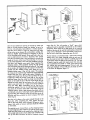
Remove
Bag
Attach
the two
octagon
_he box
to insure good
from
shppmg
shaped electrical
to
sheet metal
the
rear of
screws
box from
the we_det
provided
contact
on the
Loose Parts
cabinet
These screws
_th
must
be bght
Attach
the ground terminal
to the wall of the electrical
box as shown using zhe 10-32 nut, screw and Iockwasher
provided
This connection
must be t_ght
•
%
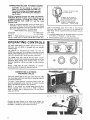
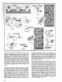
CONNECTING
WELDER
TO POWER SOURCE
CAUTION:
0o not attempt
to connect this
welder to a regular household outlet. Make sure
the power-line voltage and frequency agree with
ratings shown on the selector plate attached to
top of cabinet.
IN
Electrical connections between the welder and 230-volt,
single-phase, 60-cycle AC power source should be made by
a qualified electrician, A_| wiring must comply with the
National Electrical Code (ANSI C1) and The Local
Electrical Code,
1. install an individual
(separate)
line for
fuse block m the hne. For best results,
be as short as possible. The size of the
upon their length as shown in the table
the we[der with a
this circuit should
leads will depend
below
Supply Conductor (incl. Extension Cords)
Up to 50 feet .................
Over 50 feet .................
NOTE:
-- These
having a rated
No. 8 AWG Copper
No. 6 AWG Copper
conductor
input
sizes are for
not
more
use with
than 60 amps
_ wP]der
at 20% duty
CONNECT
The name
that your
CONTROLS
"Dual
Range" arc welder ts derwed
new arc welder =s equtpped
with
TO
HOT
WIRES
OF
SINGLE
PHASErO SYSTEM,
CONNECT
GROUNDONLY,
BURS
MAKE
CONNECTIONS
INSIDE
OUTLET
BOX
pERkY IN
LOCAL
AND INSULATE
ACCORDANCE
CODE.
INSTALL
'/ITH
COVER,
cycle in accordance
with
Article
630 of the Nat_ona{
Electrical
Code (ANSi
CI) and may not be adequate
for
other loads. Consult a quahfled
electrician
before us=ng for
other loads.
2, install 60 ampere fuses, of the delayed-action
as "Fustat'"
or "Fusetron",
m the fuse block
3. Connect
230-volt
power
hnes and ground
type such
as shown.
...............
REGARDING
KEEP
from the fact
two separate
£ANEL.
A
iii,
OPERATING
POWER
C_tBU_TIBLES
USE
FOR
_JT
MINIMUM
OF
FIRE
RA_JGE
_F V ELDI_G
US_
FOR
_FC_K_
MAXIMUM
welding ranges.
?he
be_jinner
or
less-experienced
welder
will
f_nd the
30-200 amp range easier to use because it provides extra arc
stabdlty
when welding with some of the "more d_fhcult
to
weld with specralty rods" which are prone to pop-outs
The 40-295
amp range requires
less line (input
current)
draw for any given amp setting and permits the use of the
maximum
amp
settings
w=th minimal
effect
on other
electncal
appliances,
motors,
and hghts, on your electrtcal
system.
Either
range
may
be used, depending
on
preferences when the electrode
diameter permits
operator
CONNECTING
ELECTRODE
AND WORK CABLES
Insert the tapered
plug on the end of the electrode
cable
into the proper outlet jack depending on amperage required
or operato_ preference
To Insure a good electrical
electrode plug slightly
whde
twist in the opposite
direction
connectFon
always twist
the
inserting.
To remove the plug
whde removing.
NOTE:
welding
If
you
extend
the
cables
beyond
those
already supphed,
they must
be No 3 AWG or larger to
avoid an undue
drop in welding
current
Do not extend
cables over 50 feet
Connect
the
complete
provided
the electrical circuit)
or to the welding table
it rs metalhc or wdl conduct electncl ty r
work
clamp
to
the
mece to
be welded,
(to
rtself
%
OPERATING
iNSTRUCTiONS
We feel that weldtng wtth your new
arc welder is as s_mple as A B. C.
A
Determine
what
diameter
Craftsman
electrode
should
dual
range
be used by
gauging the piece to be welded on the material thickness
gauge. The fractional
number d_rectly beneath
the bar
chart d_ctates what the proper electrode
d_ameter is for
g_ven thicknesses
of metals
diameter
of
electrodes
thicknesses
of
mater_al,
adlustmg
B
Next
the heat selector
verdy
You wgl note that a specific
can
be used on varying
Th_s _s accomphshed
by
for more
the electrode
/
or less amperage
diameter,
by placing
the
electrode
d_ameter
porbon
of the electrode
into the
gauge on the right s_de of the cabinet
bare
Because electrodes
are mass produced,
there may be
smag burrs on the bare end of the electrode
Make sure
the bare end of the rod _s as clean as possible for
accurate
C
sizing
Finally,
determine
tdent_ficatlon
the
on
the
type
package
of
electrode
or
by
the
by
the
American
Welding Soctety number stenctlled
on the coated portion
of the electrode,
bearing in m_nd the type of electrode
you have chosen
E6013 or E7014,
and also _ts'
diameter (as prewously
determtned)
Locate that band on the amp scale There are two
bands and two
E7014
bands,
use the band
coordinates
w_th the amp range you have selected.
Now
loosen
pointer
electrode
the
heat
selector
knob
Tighten the heat seEector knob
Insert
the
electrode
cable
mto
(dependmg
on the range selected)
clamp
move
matching
window.
[he
your
the
proper
Connect
the
tack
work
to the work
Wear Welding
Turn
and
untd
the fractional
number
diameter appears m the pointer
E6013
which
Helmet.
the On-Off
swttch
to the
"ON"
positron
and you
are ready to weld.
Because metals vary m their make up and the techntque
of each operator
[s different,
you may find _t necessary
to increase or decrease the amperage output
accordingly
CAUTION.
Do
not
loosen and move
heat
selector
whde
welding.
The
duty
cycle
ratings
bracketing
the amperage
scales are
provided
for your convenience
and protection
of your new
welder
Duty cycle is the performance
level of the welder
based on a 10 m4nutehrnespan
Fo_ example wetdlng for 6
minutes
out
of
10
possible
overheatlr_g
could
shorten
the
duty
c,/c_es
t_ied
minutes
_s a 60%
of _he
hfe of your
ON "h_
_e_dlng
,velde_,
r-213 _D'3_ _"
dut,,
c,,,ele
Tc
a,c
tTal,s{o_q_',_ '
_ h _'
Dc [.Jo7 v<.-._,J
tr
!
TROUBLE
SHOOTING
WARNING:REMOVAL
OF THE
REASON
MUST BE
TECHNICIAN.
TROUBLE
WELDER
CABINET
TOP
DONE BY A QUALIFIED
PROBABLE
Fan and welder do not
operate, or continually
blow fuses.
1. Use 60 ampere
fuses of the delayed
action type such as "'Fusetron"
or
"'Fustat"
or 60 ampere 240 volt
mrcutt breaker.
fuse, or opeR
breaker.
3. "ON-OFF"
Can't hold an arc.
SUGGESTED REMEDY
1. Improperly fused or
protected.
2. Blown
circuit
Welding current low
or weak.
CAUSE
sw=tch not "ON".
2.
Replace fuse, or reset the ctrcu_t
breaker
3
Turn switch
1. Have a voltage check performed
the local power company.
2. Welding current
setting too low.
2. Check current recommended
the electrode being used.
for
3. Poor connections.
3
and
1. Using a D,C, welding
rod
1. Use ACor
2. Low hydrogen rod.
2. Use rod of 3!16-inch
maximum
d=ameter, or smaller
amp range or lower
on 30-200
Check electrode holder, work
electrode cable connections.
TIPS
FAN MOTOR:
No provision has been made for
motor, as extra large otl reservoirs
for the hfe of the motor.
lubricating
the fan
provide
lubrication
PLUGS OR CONTACTS:
WARNING:
BE POSITIVE YOU HAVE DISCONNECTED
THE POWER SUPPLY TO THE WELDER.
DO NOT REMOVE CABINET TOP OR
SELECTOR PLATE.
If for any reason the selector plugs or mating contacts
become burned or pitted, they should be cleaned with a
fine grade of emerycloth or dressed very bghtly w=th a
fine file.
8
"ON".
1. Low line voltage.
SERVICE
SELECTOR
FOR ANY
SERVICE
AC-DC rods
by
t:RRFTSMRNo
A COMPREHENSIVE
GUIDE FOR YOUR
NEW CRAFTSMAN
ARC WELDER AND
WHAT iT WiLL DO
CONTAINS:
INFORMATION
• VARIOUS
• USEFUL
ABOUT
TYPESOF
RODS
ACCESSORIES
• TIPS ON CUTTING°
AND BRAZING
WELDING
J
Form
No. SP574-4
_'_
r.._o_.;__ _,_
__
,_j_
___,_
,L_
TABLE
.
OF
CONTENTS
Page
Your Welder and What It Will no
.............
1-3
How the Craftsmen Contact Rod Simplifies Welding
Wkat Happens When You Weld? ..............
1-3
1-3
Read Before Welding
14
Learn By Doing
......................
..........................
1-5
Position Welding .........................
Cest-lron Welding ........................
t-t 1
1.14
Hsrd Surfacing Worn Cutting Edges ..........
The Twin Carbon Arc Torch
..............
1-15
1-16
Cutting and Other Milcellaneo=JsOperations
, ..
Inert-Gas Metal*Arc Welding ................
Read
this Manual
carefully
for additional
SEARS, ROEBUCK AND COMPANY
AND SIMPSONS-SEARS
LIMITED
1-2
!-17
1-19
welding
information.
YOUR
WELDER
and what it will do..,
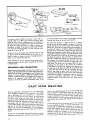
Your CRAFTSMAN Arc Welderisa sturdilyconstructedandthoroughlytestedmachineengineeredto
give many years of efficient trouble-free service. It is listed by Underwriters' Laboratories,
incorporated,which meansthat it passes
all requirementsof safety, fire hazardandtemperaturerise
limits asspecifiedin their Standardfor Transfer-TypeArc-WeldingEquipment.
HOW THE CRAFTSMAN ELECTRODE
SIMPLIFIES WELDING
Craftsman
Contact Electrode is self-starting--plusautomatic
restarting... The electrodestartson contact.
Craftsman Contact Electrode is self-cleaning ... Under nnrmai
conditionsthe slagremovesitselfasthe weld cools.Spatter is almost
non-existent. Craftsman Contact Electrode has an exceptionally
good appearance .., With fine ripple, unusually clean, smooth
appearance,and reducedslaginclusions.
Craftsman Contact Electrodedepositsmoremetal faster.., Because
the powderediron in the flux goesinto the weld.
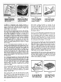
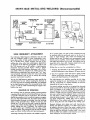
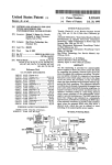
W H AT
H A P P m=N S
VHEN
YOU
WELD?
Arc Welding is the process of fusing two or more pieces of
metal together to form one piece. It is c=ccompiished by
heating adjacent metal surfaces to the melting point with an
electric arc, then adding o sufficient amount of molten
metal to provide reinforcement and fill any vacant space
between the parts being joined, as shown in the accompanying illustrations.
The arc is created when an etectrlc current, regulated by
a welding transformer, flows across an air gap between an
electrode and the work being welded. The intense heat
generated by the arc is ideally suited for welding, c=sit
can be directed to affect only the part of the metal to be
welded. Uniform heat from the arc, is acquired by keeping
its length the same for a given rod size and current setting.
At the instant an arc is "struck", a portion of the base
metal directly beneath it, is melted, resulting in a small
pool of molten metal, some of which is forced out by the
blast of the arc and deposited along the weld path. The
depth of the crater thus formed, is the distance the weld
will extend into the base metal and is referred to as the
penetration of the weFd.
1
3
Beth edges of the metal
are heated by the arc,
until --
more molten metal and
flux is added from the
rod, which -5
2
4[
they melt and flow teEetherforminE one piece,
instantly--
fills the crater and covers
the top of the weld with
slag.
This process continues the entire length of the weld,
Some of the electrode (which consists of o metal rod surrounded by a flux coating) is melted simultaneously with
the base metal and is carried by the arc to the liquid pool
This added metal combines with the base metat to form
the deposited weld.
During this operation a part of the flux coating burns off
and forms a gaseous smoke screen that completely envelops the arc, protecting the molten meta_ from harmful
effects of oxygen and nitrogen in the surrounding atmosphere. The remainder of the flux coating that melts is
carried to the molten pool where it mixes with the metal
to combine with various impurities. It then floats to the
surfaces to form a coating of slag which covers the deposited weld metal, protecting it from the atmosphere and
retarding its cooling.
_3
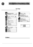
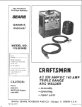
READ
BEFORE
_
_
/VELD|NG
BAND
HEA, D
GASKET
LENS
AiUSTABLE
SPECIAL
CET_R
HEb_ET
,/
/
LEATHER GLOVES
SPECTACLE
HELMET SWINGS
UP TO
CLEAR THE FACE
TYPE
GOGGLES
1/4-INCH
STEEL
SHOES
C-CLAMP
SAW
HORSE
W1RE BRUSH
GROUND
CABLE
o
When operating a welder, certain precautions must
be taken to prevent minor injuries
to yourself and
others. Although injuries may not be serious or permanent, knowing how to use the protective equipment to safeguard
against them is the first step in
learning to weld.
The effects of heat and light given off by the arc, whde
electric welding, may be compared to that of the sun's rays.
Even greater precautions are necessary for electric arc
welding. Before starting a weld, caution anyone in the
immediate vicinity against looking at the arc. In case of
accidental eye iniury, contact a physician immediately
To protect the face and eyes a heat-resisting, hbreglass
helmet is used. The special lens, which allows the user
to view the arc safely, is inserted rata the framed opening
of the helmet The dear glass, which should be replaced
from t_me to t_me, protects the expensive special lens
from breakage and weld spatter. The _elmet is held firmly
_n place on the head with an adjustable head band, thereby
leaving both hands free. A close-fittlng skuff cap should
be worn w_th the helmet. As the he)met _sused only when
actually welding, a t_ltmg arrangement permits _t to be
swung up clear of the face. When the welding _sresumed
a s|ight nad of the head tips the helmet down over the Face.
To protect the eyes further wh_le cleaning the weld, goggles
should be worn by the welder and others working around
him. Animals are also affected by the rays and should be
kept at a safe distance.
To safeguard the hands against heat and weld spatter,
gauntlet-type
leather gloves s_ould be worn. A leather
jacket will give beiCer protection against the shower of
sparks than ordinary clothing. H_gh top shoes (not oxfords)
should be worn. If a great deal of welding is to be done,
foundrymen's
shoes are best.
Precautions must also be taken to protect property and
equipment against fire. A large fire extinguisher shouTdbe
within easy reach. The we_ding area should have a concrete
or cinder floor, kept dry and dear of inflammable rubbish.
Sometimes, it _s necessary to weld close to a fuel tank. If
practical, remove the part to be welded If not, dram the
tank and completely fill it w_th water.
Few tools, in addition to those supplied w_th the welding
machine, are needed and most of them can be found in
the average shop Two sawhorses supporting a 1/4-inch
steel plate makes an excellent welding table A permanent
bench, using the same steel plate, can be made of angle
iron or p_pe. A ch_pping hammer is used to clean slag off
a weld and phers will be useful for handling hot metak A
w_re brush _sused to dean the work before welding and
remove small pieces of slag after chipping.
Small pieces of todd-steel scrap iron, reasonably free of
rust and paint, should be used for prachce welding. Angle
iron, bar stock or plate steel are good examples. Do not
_sse scrap cast iron, high carbon or hardened steel as these
rneta|s require special electrodes and welding techniques.
These should be set aside for future practice after completing elementary practice lessons
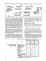
LEARN
BY DOING
90
OF
WELO
OiRECTIOH
Expe_ience has proven that short periods of practice at
regular intervals are the best way to teach yourself how
to weld. As learning to weld is simply a process of trial
and error, all practice work should be done on scrap metal
that can be discarded. Do not attempt to make repairs on
valuable equipment until you have satisfied yourself that
your practice welds are of good appearance and free of
slag or gas inclusions. Remember, what you fail to learn
while practicing, must be learned through a series of
mistakes and rewelds later on.
A comfortable body position is important when learning,
as tensed muscles will result in fatigue and lack of contro].
Sit on a low stool and grasp the electrode holder in one
hand with the cable drawn across the lap. Allow enough
slack to move the holder freely and yet keep the weight
and drag of a long length of cable from becoming tiring•
The ground connection is as much a part of the welding
circuit as the cable and electrode holder. A poor ground
connection can render the best welding equipment inefficient. When using a table with a steel top, fasten the lug of
the ground cable to it securely with a bolt or C-damp, so that
any piece of iron placed on the table top will be propedy
grounded. If a steel table is not used, connect the ground
cable dlrecfly to the work wlth a ground clamp or bolt.
Select a fairly large piece of steel plate approximately
1/4-inch thick and clamp it to the table top to prevent it
from lifting, should the electrode stick or "freeze" when
Figure
1
first
attempting
to weld. Insert a small,
mgd-steel welding
electrode
in the electrode
holder
and connect the welding
cables to produce
the heat specified
by the CONTROL
panel. Connect the ground
cable to the work and set the
indicator
in
the current
range
recommended
for
the
diameter
of rod used.
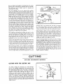
Any method of bringing the tip of the rod in contact with
the work, then quickly raising it until there is approximately
a 1/8*inch gap between the rod and the work, will start an
arc. The easiest way for a beginner to strike an arc is to
scratch the tip of the rod a short distance on the surface of
the work, as you would a match, then lift it (qulckly) the required 1/8-inch (fig. 1). Another method is to strike the work
a hard blow with the tip of the rod and allow it to bounce
up to form the arc gap. The important thing is to strike
the arc quickly and not al]ow the rod to remain in contact
with the work.
A common
mistake often made by a beginner is to point
the rod toward the work and, after
lowering
the helmet,
feel slowly about until the tip of the rod touches the work.
This always results in sticking
or "freezing"
of the rod
which produces a direct short circuit.
When this occurs the
rod can be loosened by bending
it from side to side while
pulling
on the holder (fig. 2). If this fails, turn the welder
off. The electrode
must be released in a matter of seconds
to avoid unnecessary
heating of the welder or damage to
the flux coating on the rod.
Figure
2
\
\
To strike an arc, scratch the
end of the rnd on the plate
and then quickly raise approximately 1/8-inch.
Should the rod stick or
"freeze" bend it from side
to side while puHing upward
on the rod holder.
\
\
_5
I I
t_
*_ _._
_
// //
X.,'///J//I///'/f////_
F_ger_3"
To lay a weld beadonlytwo
movements
are used, downwardandin the directionthe
weldis th be laid.
Figure 4
Watch the Weld puddle to
keep the slag from flowing
in front of it, causing inclusions and gas pockets.
If difficulty is experienced offer repeated attempts to
maintain an arc check the ground connection for proper
contact with the work. If this does not help, increase the
welding current. Also check the rod size, as larger rods
require higher current settings.
Practice striking and maintaining an arc for a few seconds,
then snap it out by rapidly pulling the rod away from the
work. Repeat this operation until the arc can be started
and the gap maintained as uniformly as possible. In a
short time you will find the arc length can be controlled by
the crackling or "frying" sound which may be recognized
by gradually shortening the arc until it sputters irregularly
as though it were going to "choke out" and stlck--then
slowly lengthening the arc by pulling the rod away from
the work until it snaps out. Somewhere between these two
extremes the steady crackling sound of a proper arc tength
will be heard.
To lay a weld bead, only two movements are used., o
steeay downward feeding of the rod to maintain the correct
arc length and a slow travel in the direction in which the
weld is to be lald (fig, 3). _/atch the weld puddle and
arc length, and move the rod steadily in a straight llne as
the back end of the crater fills up (fig. 4), The slight c=ngle
of the rod will keep the flux or slag flowing over the
deposited weld metal to form a protective coating. If the
rod is moved too slowly the slag will flow in front of the
puddle and be trapped in the weld, producing inclusions
and gas pockets.
Lay a bead approximately four incheslong. After allowing
it to coot slightly, remove the slag coating, which covers the
top of the weld, by scraping along each edge of the weld
with a cold-chisel to]owed by wire brushing until it is bright
and clean, inspect the surface of the weld carefully before
starting another. The surface of a good weld is rippled
uniformly, which results from o steady rate of travel and
uniforrr arc length.
Figure
5
Figure
Fill the crater, when starting
a new rod by striking the
arc at A thee movng to B
and back to C position•
6
Te widen the bead. work the
rod from si[le to side slightly, with a slow. zigzagging
crescent-shaped motion.
laying a number of beads,
try
"working"
the rod
from side to side slight y (fig. 6). This movement should
be slow and not wider thcsn the diameter of the rod being
used. Experiment with different current settings, rod sizes
and rates of travel. Compare results with welds shown in
the diagrams (fig. 9).
After
Too low a current setting tends to deposit the bead on top
of the plate with very little penetration. The arc sound wi[[
be an intermittent crackle with irregular sputtering. Too
high a current setting (for the size of the rod oeing used)
will provide sufficient penetration but the bead will be thin
ana undercut in places. The arc makes a hissing sound and
the rod becomes red hot before it is half used.
If travel is too slow it will pile up a wide, heavy bead with
good penetration but with overlap of the weld metal on
sides without fusion. A large area surrounding the weld is
heated to a high temperature which produces distortion,
even on a stmple weld. If the rod is moved too fast the
small bead will result with little more thor melted base
metal. An extremely" long arc causes the rod to melt off in
globules, with litrle or no penetration, and a very irregular
weld surface. The arc produces a hissing sound.
A good weld laid with correct current setting, speed and arc
length will produce a surface that is rippled uniformly, with
the same width throughout its length, and well formed
crater. The cross-sectlonal view shows it to have good penetratlon and no undercut or overlap.
If the scrap plate used is small, it will become very hot after
laying a few beads. This will alter welding conditions
which could be very confusing to a beginner. Have several
scrap pieces handy so each mc_y be allowed to cool before
laying a second bead.
When starting with a new rod, chip slag from the crater
and strike 'i-he arc at the forward end as shown at "A'" in
figure 5. Then move the rod to B and back to C, a
about twi_e _
fi0t_ai raf_ of travel to give the rod a_d
base _et_l tim_ t0:_f
up T0r proper fusion.
Figure
7
Lay the weld beads about
one inch apart, gemove the
slag and examine each wed
before starting the nexL
Figure 8
A pad of welfl metal is built
up by running a series of
beads in layers at right
angtes to each other.
CURRENT
TOO
LOW
Arcis difficult to maintain.
T_AVELTOO FAST
Sman bead undercut in
some p_aces. Rough top
and little penetration.
Very little penetration. High
bead.
CUREEHTTOO HIGH
Wide thin head, undercut.
Crater pointed and long,
Rod burns elf very fast.
Surface
ef weld
rough.
Rod melts off in globules.
Are makes hissing sound.
TRAm/ELTOO gLOW
Metal piles up, making a
wide heavy bead, overtapped at sides in places.
Uniform ripples on su_ane
of weld. Arc makes steady
crackling sound.
ARC TOO LONG
NORMAL CONDtTIONS
Figure
Practice laying beads approximately
one inch apart until
a good we_d can be produced with all the different rod
sizes the welder wilt handle (fig. 7). After becoming pro_
ficlent in running a bead, build up a pad of weld metal
Clean each bead before laying the next and make sure
they are fused together (fig. 8). Run the second layer at
right angles to the first and the third at right angles to the
second, etc.,.until a pad approximately 1/2-inch thick has
been built up. This type of welding _s used to build up
round or flat surfaces or reinforce parts that are rusted thin.
9
Figure
10
To avoid distortion when building up the end of a shaft,
run the beads paralle! to the axis and lay each successive
bead on the opposite slde as shown by the numbered steps
in figure 10. Cover the entire shaft with weld metal for
the desired length. If the place to be welded is not at the
end of the shaft, weld around it and turn the shaft slowly
to keep the we|d puddle tn the flat position _fig. 11). Clean
off the slag after each bead, then machine the shaft to
proper size.
17
FLAT
WELDING
SLIGHT
GAP
nff
'lffiff.g_
SHEET
METAL
f p,.JLET
WIELD
L____I\
RACK-UP
STRIP
Frgure 4
vrt19
LAPWELD
TACK
Figurel i
i
]lr
Figure
3
WELOS
Fcgure
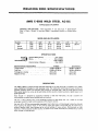
Fiat welding includes all types of joints in which the weld
is horizontal, and the electrode is fed down as m the practice
welds of previous pages. The five types of joints in figure 1
can be welded in the flat position.
Butt welds on light material should be practiced first on
scrap stock. Use 16-gauge mild steel sheet metal (approximately 1/16-inch thick) and 5/64-inch rods wqth the welder
set at approximately 30 to 50 amperes. Butt edges of metal
together and tack-weld approximate]y every three inches
(fig. 2). (Tack welds are small beads 1/4 to 3/8-inches in
length.) Place bars of scrap iron under ends of the work to
provide an air space above the table. Simply move the rod
in a straight line directly above the edges to be (greed
If the weld burns through in places, reduce the welding current or increase the rate of travel. Some difficulty may be
experier_ced in starting the arc at these low current settings.
Figure
Figure
5
7
8
t-.t-- GAP
FIRSTPASS
E V-WELD
However, once the arc Js started, there will be sufficient
heat to make a sound weld. After laying a bead, turn the
work over and inspect the underside which should also have
a small uniform bead. To prevent burning through where
the edges are not butted t_ghtly together, move the rod back
and forth with short quick strokes in the dlrechon of the
weld to brTdge the gap and give the metal in the crater a
chance to solidify (fig. 3).
Butt welds on sheet metal hghter than 18 gauge should
not be attempted by the beginner without the use of a
back-up strip (fig 4) This consists of a bar of copper
clamped tightly against the underside of the seam to absorb
the heat of the arc and prevent the weld from burmng
through. To assure complete penetrahon with butt welds
on 8-gauge metal or heavier, a 1/16 to 3/32-inch gap
should be altowed between them (fig 5) Insert a wedge or
screwdriver between the plates when tack-welding to maretam the gap, then turn the piece over, so the tack welds are
on the underside
Use enough current to melt edges of ploFes to o depth of
at least one-half their thickness Clean off the slag and
respect it for smoothness, penetration and height of remforcernent A good weld should have a reinforcement shghtly
more than flush with the surface (f_g 6)- Turn the plate
1-8
T_IRD PASS_
SECONDPA_S
Figure 9
REIHFORCING
_
(WEAVE)
E-BEVELW£LO
_PAS$BlrffWELD
Figure
10
over and weld a slm_iar bead on the other side (fig 71 A
hEgher welding current can be used on this s_de as there ws
no danger of burning through and fusion with the first
bead will be assured
Although butt welds can be made on steel plates up to
3/8-inch thick, with a 295-ampere machine using 1/4-inch
rod, the same results can be obtained with the 180 and
230-ampere machines if edges of plates are beveled (fig B)
Metal of almost any thickness can be welded m th_s manner
by depositing a number of beads, one on top of the other
until the groove _s completely filled. If the plate can be
welded from both sides, always use a double bevet (fig. 9)
]f only one plate _s beveled, the angle should be at 45 degrees fflg. 10).
Run the first pass on beveled plates with a 5/32-inch rod
and Jse as high a current as you can handle to obtain a
small bead on the underside. If this is not done, insufficient
penetration will result, as shown in figure 11. Be sure to
clean each pass before laying on the next. All beads are
laid by mowng the rod in a straight line with no weaving
or side-to-slde movement. On the last or reinforcing pass,
a weaving motion must be used to obtain a wide weld that
will completely cover oreceding beads. For the beginner,
the side-to-side movement .with a slight hesitation at each
end) will produce a smooth too without undercut or overlap.
UNDERCUT GAS POCKET
ENT
PENETRATION
Figure
11
Figure
Figure
12
13
FILLET
Select several practice welds of different thicknesses and
cut them into 1-1/2-1nch strips. Clamp each strip in a vise
and bend it at the weld (fig. 12). If it breaks through the
weld, study it to find the cause of failure.
Corner welds are made on light sheet metal by running
a single bead along the top, after tack-welding at threeinch intervals to prevent warping (fig. 13). If numerous gaps
are present, a back-up strip may be used. On heavier
metal two passes may be necessary and, if the design
permits, a smaller pass can be laid on the underside.
Beveling may be used to advantage on the thicker metals.
WELDS
II
BREAKING
THE WELD
Figure
4
Figure
6
WELD
Fillet welds are used to join two pieces of metal with sidesor
edges at right angles to each other. The size of such a
weld is based on the leg length of the largest isosceles right
triangle that can be inscribed within the cross sectional
area, as shown by the dotted-llne triangle (fig. 1). The
size of a fillet weld may also be measured with a square
and ruler, subtracting 1/32-inch from all dimensions under
3/16-inch and 1/16-inch from all over 1/4-inch (fig. 2).
For example, a 1/4-inch fillet weld should measure 5/16inch. This will offset any inaccuracy due to the slight radius
at the toe of the weld and allow for concavity of the bead.
When cs fillet weld ]s stressed to its maximum capacity,
failure will usually occur through the throat section (fig. 3).
Therefore, the strength is determined by the throat dimension multiplied by the length of the weld. Finished welds of
this type should always be at least four times their size in
length; that is, a 1/4-inch fillet weld should never be less
than one inch long. The direction in which the load is applied
to a weld greatly affects its strength, which can be dearly
demonstrated by breaking the weJd (fig. 4). A ioint so
loaded should always be welded on both sides with fillets
equat to the plate thickness (fig. 5). If this cannot be done,
bevel the plate to assure complete penetration and position
the work at a 45*degree angle if possible.
For practice, tack-weld three pleces of scrap iron together
to form a cross (fig. 6). Use a 5/32-inch rod with high curren_
and hold it as indicated in the front and side views. Move
the rod at a steady even pace along the seam without any
slde-to-side movement and deposit one inch of weld for
each inch of rod melted. The surface contour of a good we_d
lr?
Figure
Figure
Figure
Figure tO
_
9
11
_UTTING
INTERMITTENT
WELOS
Figure 12
_
8
EXCESS WELD_
STAGGEREO
iNTER+
Figure 13
Figure+ 16
WELDS
Figure 17
LAPWELDS
Figure
14
LAPWELDS
Figure
15
should be nearly flat with a slight radius at the sides or
toes. Avoid excessive concave or convex surfaces of the
fillet (fig. 7). Undercuts and cold-laps are caused by not
holding the rod in the center of the seam (fig. 8). If the
desired fillet weld cannot be made with a single pass,
several passes are usedto build it up to required size (fig. 9).
Slag must be cleaned from each pass before depositing
the next. Fillet welds over 1/2-inch in size are rarely used
because ioints requiring more strength can be made more
economically by beveling and groove+welding, followed
by a small concave fillet weld to provide a radius in the
corner,
Horizontal fillet welding is used when the side or edge of
one member of the joint is in the vertical position particularly
for small single-pass welds where the work cannot be tilted.
For practice, tack+weld two pieces of scrap together to
form a tee-jolnt (fig. 10). Use a 5/32-inch rod held at
angles indicated, and direct the arc into the corner ot the
joint. The arc length should be somewhat shorter than for
flat fillet welding. To assure penetration at the root, use the
highest welding current that ca_ be handled (fig. 11).
Good penetration is of prime importance and appearance
t-)O
WELD_'\OH
BOTHSIRES
ATENDOF JOINT
will come with experience. If the arc is advanced too fast,
or held too close to the vertical plate, undercutting may
result (fig. 12). Too slow travel will cause overlapping and
an extremely close arc or low current will produce a bead
with a convex surface (fig. 13). To check the penetration and
soundnessof the bead, break some of the welds for inspection, as shown in figure 4+
When making a lap weld, care should be taken not to mett
too much of the upper corner on the top plate (fig. 14).
Some melting will take place, but proper advance of the
rod will cause the weld metal to build up and blend into the
top surface. On sheet metal, hold the 3/32-inch rod almosl
perpendicular and move the arc rapidly. Welds of this
type should be wider than they are high, somewhat like a
flat beacJ (fig. 15). A sfight discoloration on the underside
of the lower sheet indicates good penetration. On heavy
metal, a 3/8+inch fillet weld can be laid in one pass with a
1/4-inch rod using a 295-ampere machine. However, with
smaller machines, the same weld or larger can be made by
building up with a number of passes (fig. 16). When
welding long narrow pieces, stagger the welds in short
intermittent beads, first on one side then on the other side,
to minimize distortion (fig. 17).
POSUTION
WELDING
WELD
In order to derive the greatest benefits from your welder,
you should practice until you can make a welded joint
in almost any conceivable position. The ability to do this
is especially useful when making repairs on machinery as
the amount of welding in most cases is small and does not
warrant disassembling the parts to weld them in the flat
position. Welds of this type have been classified into three
groups according to their location and are referred to as
vertical, horizontal and overhead welds (fig. 1). Of the
three positions, vertical welding will be used the most and
should be practiced first. Skill gained in this type of weld
will make horizontal and overhead welding easier.
VERTICAL
WELDING
The two methods of welding in the vertical position are
commonly known as "vertlcal-down"
and "'vertical-up"
welding (fig. 2). In the former the bead is started at the
top and welded in a straight line downward. In the latter
the bead is started at the bottom and welded up, usually
with a weaving motion.
The chief difficulty encountered with any position weld is
keeping the molten metal in the puddle from falling out,
To prevent this the arc must be held as short as possible and
the weld puddle kept fairly small so it will solidify rapidly.
Vertical-down welding isthe easiest to perform and is used
on material up to l/B-inch thick. Before attempting a vertical
DOWNWELD
weld, run a few practice beads to get the "feel" of the
arc. Tack-weld a piece of scrap iron to an old practice plate
so it is positioned vertically (fig. 3). Use 1/8-inch rods for
the first welds and a current of about 75 to 115 amperes.
Experiment with various amperage settings until you are
using the highest current you can handle. Hold the rod at
right angles to the plate laterally, with the tip pointed up
at the angle shown in figure 3. Start the weld at the top
of the plate and move the rod in a straight line downward.
The correct rate of travel can be determined by gradually
reducing the speed until molten metal in the puddle can no
longer be kept in place. Then, increase the speed slightly
while watching the puddle, arc length and angle of the rod.
A short arc provides better control of the molten metal.
Follow the same procedure with 3/32 and 5/32-inch rods.
It will be noted that the larger the rod the more difficult it
is to control the puddle. For this reason smaller diameter
rods are always used for position welding.
Lap or tee-joints are made by simply directing the arc into
the corner of the joint as in flat welding and moving the
rod down the seam at a steady pace. Butt welds may require
more practice, as there is a tendency to burn through on
light gauge material. If this occurs, continue until the seam
is completed and patch the hole by chipping the slag and
wire brushing until clean. Then, with slightly lower current,
strike an arc on the weld directly above the hole and quickly
bring the rod down to the lower rim of the hole to deposit
a small amount of metal. Raise the rod for an instant to
let the metal solidify and repeat until the hole is welded.
Hold a long arc when raising, so there will be no metal
deposited except when the rod is lowered. Any hesitation
in the rate of travel will cause a "burn through." If this
happens repeatedly, lower the welding current.
Leave a slight gap between pieces for butt welds on material
over 3/32-inch thick. Inspect the back side after welding
for small bead along the seam, indicating complete penetration (fig. 4). Butt joints on material around 3/16-inch
thick should be welded on both sides.
Vertical-down welds may be made on heavier material by
laying in a number of passes (fig. 5), however, this practice
is not recommended as it takes longer than a heavier singlepass weld made by the vertical-up method.
VERTICAL-DOWN
9_
/3RO PASS
IRSD£_
-2gB PSi;
A SM,
ALLS_ OP4
g_K SiDE|IIOBAWN
COIIPLET_
P£WET_Tt
0g
_ure
3
Figure
4
Figure
5
iii
VERTICAI..UP90°
WELDING
Figure
7
Figure 8
Figure
6
F;gure
TO
r_
Use 1/8 and 5/32-inch rods for all verticabup welds and
sta_" by running practice beads from bottom to top of a
3/16 or 1i4-1nch plate, tack-welded in a vertical position
Hold the rod as shown in figure 6, noting that the angle
of the rod is not as steep as for vertlcal-down welding, but
tdted just slightly (approximately
five degrees) so the tip
of the electrode points upward. Strike and hold a short arc
until a small amount of metal _s deposited, then quickly
raise the rod upward w_th a wrist movement to increase the
length of the arc at the top of the stroke (fig. 7). As soon
os the metal deposited in the crater hes solidified, bring the
rod down and deposit more metal. Keep repeating this
whipping motion, while gradually moving the rod upward
and toward the plate as the electrode burns off. The length
of the stroke will depend upon the amount of metal de_
posited and the welding current used. Keep the rod in
constant motion once it has left the crater. The purpose
of a long arc is to prevent any metal from being deposited
except when the rod is held at the crater. If globules of
molten metal drop from the tip of the rod when the arc is
lengthened, either the current is too high or the rod has
remained away from the crater too lang. Care should be
taken not to break the arc Qt the top of the stroke. Do not
deposit too much metal at one time as this will cause the
weld to sag and result in a high narrow bead undercut
along the sides• Better penetration can be had by the
vertical-up method• This can be demonstrated by joining
two pieces of 3/16-inch metal with a butt weld, using the
whrpping motion. Leave a gap between the plates and use
a 5/32-inch rod with a fairly high current, determined by
experimenting. The whipping motion wifl melt the corners of
the plate and form a pocket in wh]ch to deposit the weld
metal (fig. 8).
weave (fig. 9). This will produce a "shelf" upon which
additional metal is deposited intermLttentlyas the welding
progresses• There should be a slight pause in the weaving
mot_an at the toes of the weld to avoid making a bead that
is too convex. Materials 1/4-inch and thicker must be beveled on one or both sides, depending upon the joint.
Practice making a wide bead using a side-to.side weaving
motion with a very shght whipping action at each end to
give the metal at each end a chance to solidify and avoid
undercutting along the sidesof the weld (fig. 10). This type
of bead is used on welds that require more than one pass
and is colTed the finish bead or "wash" pass. Hold a short
arc, making the bead approximately 3/4-inch wide and
fairly hght, Multiple verticoLwelds may be made as shown
in the series of diagrams, figure 11.
÷
r pASS
TOP _
I$!
Burn the rod in deep so the crater extends through to the
back side. After completing the weld, inspect the back
side for the smalt bead, whLch indicates 100-percent penetration Buff welds on heawer materials should be welded
on both sides.
On materials up to 1/4-1nch thick, use the whipping motion
on small single-pass fillet welds for lap and tee-joints. Larger
single-pass fillet welds can be made by the whipping motion
with a slight slde-to-slde weave added and combined with
the up and down movement to make a triangular shaped
Frgure
I 1
i il
Figure
14
)
Figure
12
+
OVER-LAPPED
Figure
HORIZONTAL
13
BACK-UP
STRIP
Figure
15
Figure
16
Figure
17
WELD|NG
Horizontal welding refers to one type of butt weld between
two plates in a vertical plane. For practice, set up a plate
as for vertical welding and run straight beads across from
left to right (fig. 12). Use tFe same current settings as for
vertical-down welding and hold the rod as indicated with
a short arc. Move the rod in a straight llne and deposit
a light bead. The rate of travel will depend upon the current
used. Too slow a travel will cause the bead to sag (fig. 13).
Practice with 3/32, 1/8 and 5/32-inch rods until a well
formed bead can be made with each size rod (fig. 14).
Sheet metaJ up to 1/16-inch
OVERHEAD
HOLD A LOHSARC
UP SIROKE
thick can be butt welded from
one side. If the seam has numerous gaps, use a back-up
strip, allowing a slight gap between edges of 1/8-inch
thick metal and weld from both sides (fig. 15). All metal
3/16-1nch thick and over should be beveled and welded
with a number of passes (fig. t6). Thoroughly clean each
bead before laying the next and use higher current than
for single-pass welding.
The appearance of a multiple-pass horizontal weld can be
improved by vertical down beads lald closely together.
Use a swift circular motion to the right; slowly downward
while welding (fig. 17).
WELDING
Although overhead welding is generally considered diffieu]t, do not become discouraged, as it is being done every
day by people who have taught themselves. Once the art
of maintaining a short arc has been mastered, the rest
will be easy.
Since there will be a shower of sparks, wear a leather
jacket and keep the practice plate slightly higher than the
top of your head when standing. To keep sparks out of your
gJove, grasp the electrode ho]der as indicated in figure 18
and ho]d the rod in a nearly vertical position with a slight
tilt to the right+ Drape the cable over your shoulder so its
weight will not interfere with the use of the electrode. Use
1/8-inch rods and a current setting the same as for vertical
welding, and move the rod in a straight line without any
weaving or whipping motions. A reasonably fast rate of
travel must be used to prevent the bead from sagging and
undercutting along the edges. Vary the rate of travel and
notice its effect on the size and appearance of the weld.
When you feel you can run a satisfactory bead, try the
slde-to-side weaving motion and deposit a thin weld approximately 3/4-inch wide. Themovement must be somewhat
faster than for other positions to keep the bead from
sagging. (This method of weaving is used on]y for the
last pass on heavy welds where improved appearance is
necessary.)
The whipping motion is used where a gap exists between
the plates as it provides better penetration with higher
welding current. For practice work, set up two plates approximately 1/8-inch thick, allowing a gap between them.
Burn in deep for good penetration with 1/8 and 5/32-1nch
rods, varying the plate size and gap distances.
F;gure
18
Figure
19
Fillet welds for lap or tee-joints are most common in the
overhead position. Tack+weld two pieces of scrap iron
together to form a tee+iolnt, and clamp in the overhead
position so one plate is held vertically (fig. 19). HoLd the
rod at angles indicated and deposit a light bead from left
to right without weaving or whipping movements. A slightly
higher current than used for overhead butt we_ds will be
necessary to get good penetration at the root of the weld.
_-_3
DISTORTION
WHEN
TRENDS
COOLING
BUTT W£L_
Figure
_T
Figure
IST mLBH_
T_ yRt9 _.
ET_
20
Figure
Figure
When you can lay slngle.pass butts and hllet welds you will
be able to make an overhead weld of any size, as it is
simply a matter of fusing a number of straight beads together, one on top the other (fig. 21).
Weld appearance can be improved by grinding with a
properly guarded abrasive wheel mounted on the end of
a flexible shaft.
AND
CONTRACTION
Metals expand when heatedi contract when cooled In arc
welding, the deposited metal and edges being joined are
molten and the metal surrounding the weld is heated suffiaently to cause expansion. When the deposited metal
so|id_fies, it becomes a part of the plates; but, being unrestricted in its expansion in the molten state, it tends to
contract more than the heated surrounding metal If the
CAST
iRON
Previous experience in handhng the arc, plus good ludgrnent regarding
expansion and contraction, wdl enable
you to weld grc_y cast Iron successfully m a short t_me.
Two types of electrodes are used, namely: non-mach_nabEe
for use in cases where the weld does not have ta be
machined, and machinable which deposits a file-soft weld
that can be drilled or machined to close tolerances NonrnachJnabJe rods are used for most repair iobs such as
cracked motor blocks, water jackets, pump and gear housings, etc. I{ the weld must be made across a machined
surface that need not be refinished to a close tolerance,
the face of the weld may be ground flush wtth an abrasive
wheel.
As cast iron is ve,"y brittle, care must be taken to control
expansion and contraction, and thus avoid cracking of the
t-14
24
21
To simulate actual conditions tack-weld a piece with an
irregular edge to another piece leaving numerous gaps
along the iolnt. Use the _vhlpp[ng motion and deposit a
fairly heavy bead, slowing down the rate of travel where
the gaps are widest to budd up a weld of umform size
throughout Its length. If the gaps are rather wide, fil_ them
first, clean off the slag and lay _n a fillet weld the entire
length of the joint (fig 20)
EXPANSION
23
surrounding metal is free to move (not clamped or tacked)
It cannot resist these forces and bends (fig 22)
The weld also contracts in width, as well as _n length,
tending to pull the plates together, resulting in locked-up
stresses(fig. 23). This is not too serious when weldlng mild
steel up to 1/2-inch thick, as the ductJhtyand elongation of
the metal will permit it to deform shghtly to compensate
for these forces, and prevent cracking On sheet metal and
light structural members, long continuous welds may cause
conslderabb bending and result in a badly distorted weldment. Fortunately most of this can be avoided by studying
the effects of expansion and contrachon, as related to the
job before welding and working out a procedure to follow
For example: first assemble the job with tack welds, and
_nstall temporary braces tack-welded to support parts that
might bend. The braces can be removed after the lob is
completed. Lay the beads GO the stresseswill counteract
or nbutralize one another, by running a short pass first on
one side then on the other, etc. Often the neutralizing weld
is at the other end of the job. Do not concentrate too many
welds m one place but space them to distribute the heat
and stresses throughout the enhre structure Use intermittent
welds whenever pass.hie, ff continuous welds are necessary
to make a water-tlght compartment, use the back-step
method as shown in figure 24, fusing each bead together
at the end.
WELDING
weld or the casting Because of tow tensde strength and
lack of ductility it cannot bend, stretch or d_stort itseJf ta
conform to the contraction of the weld metal. In same cases
_t may be necessary to pre-heat the entire casting before
weJd_ng. However, as most cast _ran welding lobs can be
clone without pre-heatmg, this method will be considered
first
The part must be free of rust, grease, paint or dirt, cleaned
by w_re brushing, grinding or washing with solvent The
crack should be beveled for penetration. If the parts are
broken apart completely, they may be ground on an abrasive
wheel to a single or double bevel, depending upon the
thickness of parts and whether or not the ioint can be
we_ded from bath sides. Do not bevel to a sharp edge along
the entire crack. Instead, allow approximately
1/16-,nch
of the fractured surface to llne up the two pieces. Tack-weld
or clamp parts in position. !f the crack has not separated
the casting, a vee-g_oove can be chipped out with a dlamond-point chisel. Chlp an inch or so beyond the visible
ends of the crack as it may extend under the surface. On
cracked water jackets, where only a seal is required, the
depth of the groove need on!y be one-half the thickness
of the casting.
Keep the casting as cool as possible and do not expect to
complete a weld in cast iron as rapidly as in the same length
in mild steel. Use a smaller rod and a slightly higher current
than for the same thickness of steel. Lay a short bead, about
an inch long, at one end of the crack and peen it immediately
with a cross-peen hammer or blunt chisel to spread the
weld metal and relieve locked-up stresses. Do not strike the
edges of the casting. Place the second bead at the opposite
end of the crack and the next in the center, etc (fig. 1_.
Allow enough time between welding to permit your bare
hand to be held on it. Never use water or a blast of air
to cool the casting. Although cracks may not show up
immediately, the locked-up stresses due to uneven cooling
will cause the casting to fail after it is back in service. Wire
brush each bead before depositing the next. Then continue
to fill the groove with short weld beads as before, worklng
rapidly when depositing and peening the bead. Allow plenty
of time for cooling. Examine the casting for cracks that may
develop during cooling periods. If any of the beads crack,
chip them out and re-weld. If cracking persists, preheat
the entire casting slowly to a dull red heat with an oxyacetylene torch or blow-torch. When the preheated method is
used, the welding can be continuous. After completing the
weld, cover the casting with warm dry sand or slaked llme
so it will cool slowly.
Malleable iron is ordinary gray cast iron that has been heat
treated to give it a tough ductile outer skin. The method of
welding is the same as for cast iron.
FIRST BEAD
THIRD HEAD
SECOND H£AD
i_ '_.4
HARD
FACmNG
WORN
CUTTING
EDGES
GR_D OFF
INOICATES
HARO FACING
HARD FACE
Ig SIDES
_PS
Figure 2
HARDFACIfH
WEJ_VEBEAHS
F;gure 3
HARDFACING
ON UNOERSID[
SOFT BASE METAL
W_ARSAWAY EASTEr
THAN HARD HAS]fiG
SPIKE
HARROW
TOOTH
MILO-STE£L
PA_/CH
WELDS
Figure
5
SWREP
Figure
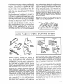
Excavating equipment, earth-cuffing farm machinery or
others such as plow shares, lister shares, cultivator shovels,
sweeps, subsoilers, spike harrow teeth, tractor treads, excavating buckets, or any surface subject to abrasive action
will last much longer and require less sharpening when
their cutting edges are hard faced with hard surfacing
electrodes. The arc welding process consists of depositing
a layer of abrasion resisting weld metal on the worn cutting
edges as indicated in red on the parts shown in figure 1.
Prepare the part for welding by cleaning the surface to be
welded by grinding it approximately
1-1/2 inches back
from the edge (fig. 2). Position the part so weld metal can
be deposited in the flat position. If the material is 1/4-inch
thick or Jess, use a 1/8-1nch rod and as low a current as
possible that will still permit the metal to flow out smooth
and falrly thin (1/16 to 1/8-inch thick). Weave the rod
from slde-to-side in a crescent-shaped movement and deposit a bead about 3/4 to 1-1nch wide. Several passes
(laid slde-by-side) may be necessary where the worn surfaces are quite wide. In some cases a small straight bead
must be deposited along the edge to build it up (fig. 3).
Make beads heaviest where the wear will be greatest, but
avoid excessive build-up as the metal cannot be filed or
machined. If shaping is required, heat the weld metal and
forge it. Smoothing and sharpening can be accomplished
by grinding.
For plow and lister shares, cuffivator shovels and similar
cutting points, deposit the weld metal on one side only
which will result in a self-sharpening edge (fig. 4). The
softer base metal on the other side will wear away first and
leave a knifedike edge of hard facing material. Parts that
must wear uniformly on both sides should be hard faced
on both sides. The condition of the worn part must also be
taken into consideration. ]f the part requires a number of
passes to bring it up to the desired thickness, use mild-stee_
welding rods first; then cover with deposited metal from
hard surfacing rods. If the edge is entirely worn away, a
steel patch (cut to fit) may be welded in place with mild-steel
electrodes, then hard faced (fig. 5). To prevent distortion
when hard facing small parts, peen the deposited weid
metal before it cools.
THE
TWIN-CARE]ON
Figure
I
The arc torch (fig. t) consists of an insulated handle with
two projecting carbon electrode holders, one of which is adjustable to permff striking and breaking an arc at the carbon
tips. A thumb knob on the handle performs the adjustment
and operates csshut-off swltch built into the handle. There
are no valves or gauges that require fine adjustment as
with an oxyacetylene torch The same protective equipment
used for ordinary arc weldmg is used when operating the
carbon-arc torch.
A wide selection of flame heats may be hod by varying
the current and size of the carbon electrodes. Ahhough the
actual temperature of the arc remains the same for any
current setting, the volume of transferable heat increases
with an increase in amperage. However, amperages in
excessof those given below will only cause short carbon life.
1/4-in. carbons
.......
30 to 40 amperes
....
TORCH
To prepare the torch for use, connect its two cables to the
ground and electrode cables of the welding machine.
Grounding of the work _snot necessary as the operation of
the arc flame is enhrely independent With the thumb knob
on the handle in the "off" pos_tlon,insert two 3/8-inch carbon electrodes in the holders and clamp in place at approximately one-half their length (fig. 2) Do not clamp them
on or near the ends opposite from the arc as this will cause
overheahng of the carbons. When tightening the clamping
screws, be careful not to apply too much pressure on the
carbons, as they are very bnttle and break easily. Use only
enough pressure to hold them firmly m place, if the hps
of the carbons do not hne up with each other, an adjustment
may be made by turning the Iorlgest of the electrode holders
slightly, too much turning will loosen it, and make it necessary to disassemble the torch to agaln tighten it properly.
Work ordinarily done with a gas welding torch _spossible
with the twin-carbon arc torch connected to an A.C. welder.
The carbon-arc flame is similar to the flame of a gas welding torch in that it provides heat by radlahon, rather than
by direct arc between work and electrode This flame heat
greatly widens the scope of work possible with the arc
welder for brazing, soldering, welding of non-ferrous metals
and localized heating for bending, forging and hardening.
5/16-_n. carbons
3/8-1n. carbons .......
ARC
40 to 65 amperes
65 to 90 amperes
Do not make any turning adlustments wdh the shding holder
as this would spo_l the contact tensRonin the sw_tch
To strike the arc, turn on the welding machine and set _t for
approximately 70 amperes Lower the welding helmet and
hold the torch up to silhouette it against the hght of a window. Slowly move the thumb knob forward untd contact
Lsmade between the hps of the carbons. Th_swLH start the
arc Then Jmmed_ate[y move the knob back to mcrease the
gap between the carbons. The actual d_stance can be determme_ with a httle prachce When the carbons are too close
the arc flame will have a sharp crackhng noise As the
distance between the carbons is increased, the crackhng
w_rfchange to a soft purring sound which md_cates the best
arc flame. There are two heat zones and the small tuner
zone _sby far the hottest, having an eshmated temperature
of 9000 degrees Fahrenheit (fig 3)
The shape of the flame greatly influences the way m which
it must be used For example, on beveled work the torch
should be held parallel to the groove so the flame wdl reach
the bottom (fig. 4). If held at right angles to the groove, the
flame straddles the groove and the heat w_ll not reach the
bottom (f_g 5) Filler rods, as for gas welding, must be used
on Iomts of tb_s type
The soft, bushy flc_me _s pressureless and has no tendency
to blow the mohen metal This _sa d_shnct advantc_ge when
welding thin sheet metal Jo_r_tsan hght mater_al should be
i
CORRECT
i
FLAME POSITION
INcoi_RECT
FLAME
POSITION
ELE Tn0_E
,k_e
\
_C
F_gure
2
F;gure
3
Frgure
i
!16
4
F_gure
5
\
bent and edges fused together by melting down the excess
metal to form a bead (fig. 6). No filler rods are required.
The carbon-arc torch is ideally suited for brazing and
soldering sinai] tubing.
Cast and malleable iron can be brazed with excellent
results. A bronze filler rod and common brazing flux are
used. Rust, paint or grease must be cleaned from the area
to be brazed. If it is a buff joint, such as a crack in a casting,
grind or chip out a beveled groove as for arc welding.
Apply the heat from the arc flame gradually by passing
it over the metal surrounding the joint. When the casting
has become warm, concentrate the arc flame at the joint.
The important thing to remember when brazing cast iron
is never to heat the edges ef the joint to the melting point.
The temperature of the work should not exceed the melting
point of the filler rod. The carbons are held as close to the
work as possible without causing the metal to bubble. Hold
the filler rod in the left hand and heat the end of it slightly
by passing it through the arc flame. Then dip the heated
end in brazing flux. Raise the torch slightly and deposit
some of the flux at the part of the joint being heated. When
the surface of the heated metal takes on a shiny or wet
appearance, the filler rod can be applied.
Do not put the rod directly in the flame, but hold it on the
work and let the heat of the edge of the flame and the work
melt the rod. Deposit only enough metal to fin the part of"
the joint that has been coated with flux. As the metal is
being deposited, move the torch along the ioint slowly,
applying flux to the rod and joint as required.
Copper and copper-base alloys such as bronze and brass
may also be brazed, but as their melting temperatures are
so close to the meItlng point of the filler rod, the process
in many cases becomes one of welding rather than brazing.
A bronze fil]er rod and common brazing flux are used.
Most non-ferrous metals can be welded by manipulating
the torch and filler rod in the same manner as for brazing,
with the exception that the edges of the joint are heated to
the melting point before depositing the filler metal, tf the
work is a copper alloy, use common brazing flux. If it is an
aluminum alloy, use aluminum flux. The filler rod should
be of the same analysis as the work. If regular welding
rod is not available, strips of the parent metal may be used.
A back-up strip should be used when welding thin material.
Small diameter carbons and low amperage setting are
used for soldering. The torch is held so the work is just within
the visible edge of the flame. Apply the soldering flux and
play the flame over the work until it is iust hot enough to
melt the solder. If the joint is to be sweat-soldered, tin the
surfaces to be joined, then press them together and reheat,
adding more solder at the edges of the joint.
One of the most practical uses of the arc torch is heating
metal for bending, forging, etc. Set the torch for a wide,
enveloping-type flame and apply the heat to the bottom of
the work (fig. 7). Since a red heat is not visible through the
dark welding glass, the helmet must be raised periodically
so the work can be inspected to avoid overheating. To protect the eyes from the rays of the arc, hold the torch to
one side and above your head. The carbon-arc torch is
not recommended for welding mild-steel. However, it may
be used for brazing mild-steel if the meta] is too thin for
regular metallic-arc welding.
CUTTING
and
CUTTING
WITH
other
miscellaneous
operations
THE ELECTRIC ARC
Arc cutting is simply the continuation of a "burn through"
such as you probabty experienced when practicing with
light sheet-metal welding. When this action is accelerated
by using extremely high currents, it becomes an efficient
method of cutting metals. Although the edges of the cut
surfaces are not as smooth as when cut with a saw or
oxyacetylene torch, there are many cases where such precision is not required. Ordinary mild-steel welding rods
may be used. The current will vary with the type and thickness of the material. In general, high currents increase the
speed of cutting but also increase the rod burn-off rate and
width of the cut.
START
CUT
HERE
,a,,_.MOLTEHMETAL
STEEL
,_
Figure
1
CONTAINER
BOLT AND
MOVI[ ROe Lip AND -_,
RIVET CUTTING
._
Removing rusty bolts or rivets is an easy job with an electric
arc welder. The arc is struck on the head or nut of the bolt
and worked around in a slight circular movement until the
head is completely melted off (fig. 4). A punch is then
used to drive out the remaining part. The boff or rivet can
be removed by heating the head almost to the melting point,
then quickly shearing it off with a cold chisel Care must be
taken not to cause the bolt to become welded to the metal
_.
START
CUT
HERE
HOLE PIERCING
F_gure 2
To make a trial cut, place a bar of steel approximately
1/4-1nch thick on the table so that ene end projects over
the edge. Use a 3/32-inch rod and a current setting of
around 140 amperes. Hold the rod as shown in figure 1 and
strike an arc on the top corner at the edge of the bar where
the cut is to be made. Feed the rod into the molten puddle
and keep the crater burning through as the rod is moved
across the bar. To catch the molten metal, place a metal
container an the floor directly under the cut.
When cutting metal heavier than 1/4-inch, the arc is started
at the bottom corner and worked up and down vertically
as shown in figure 2, advancing the bottom of the cut
slightly ahead of the top of the cut to permit molten metal
to run out more easily. If a smooth edge is desired, the
pieces can be ground on an abrasive wheel. Electrodes
designed especially for cutting may cllsobe used.
REMOVING
SEAMS
Another useful appllcahon of the welding arc is piercing
holes in metal. Coated metallic electrodes are best for
this purpose because of their small size and insulation
afforded by the coating. The process is extremely fast and
a surprisinglycleon circular hole can be made. Far practice,
place a piece of scrap iron I/4-inch thick (or less) on the
table and allow it to project over the edge as for arc
cutting. Use a 3/32-inch rod and the same current as for
cutting. At the place where the hole is to be pierced, strike
an arc and hold it until a molten puddle is formed. Then
push the electrode down against the molten puddle and
force it through the plate. It ispossible to hold the e4ectrode
against the melted plate because the metal core melts off
faster than the coating The coating (not the rod) touches
the molten metal (fig. 5). The gap malntamed by the protruding coahng prevents the metal core of the electrode
from sticking or freezing to the plate.
If a larger diameter hole is desired, first pierce a hole as
described. Then, holding a fairly long arc, melt the edges
of the hole away by moving the rod around it (fig. 6). Holes
of almost any diameter can be made. To pierce a hole
through material thicker than 1/4-inch, work from the
underside.
In addition to cutting, the electric welding arc can be used
for beveling the edges of material to be welded, gouging
out cracked welds for rewelding or removing tack-welds.
The surface of the metal being worked upon should be approximately in the vertical position, or tipped slightly toward
the arc (fig. 3). Start at the bottom of the seam to be gouged
out and work upward. The rate of speed will depend upon
the depth of the groove and the amount of metal removed.
HEATING
The carbon arc prowdes a convenient method for localized
heating of all metals. Simply strike an arc on the part to be
heated and "play" it across the surface unfit the required
temperat_ureis reached
MOL1TN
GOUGINe
Figure
1-1E
3
Figure
4
FJgure 5
Figure
6
INERT-GAS
METAL-ARC
GROUNDED
WORN
PIECE
ALLCABLES
ORWORN
TABLE
SHOULD
BE
/
NEPTSHORT TOELECTRODE
ASPOSSIBLE
(Donot exceed12-U2
feetin length)
H E ATE
GROONDCABLE
J
_
-
WELDING
(Nonconsumabme)
ANYCRAFTSMAN
WELDER
MAYBEUSEO
WITHHF
ATTACHMENT
(
WELDER
GROUND
I
CABLE
o
o
230 VOLT
WELDER
CABINET
MOST BE
GROUNDED
_HOCYCLE
SINGLE
PHASE
/
WELDINGCABLETO WELDER
HIGHFREQUENCY
ATTACHMENT
F_ure
HmGH FREQUENCY
\
Figure 2
I
ATTACHMENT
The Craftsman, High-Frequency Attachment may be used
with any Craftsman welder or other single-phase, transfarmer-type welder of high quality construction having an
AC, or AC/DC power output Tungsten inert gas (T.kG.)
welding has many useful and advantageous applications
as described in the following paragraphs. In order to use
the T.LG. process w_th an AC welder, a htgh-frequency
attachment must be provided Figure 1 shows a typica_
hookup using this high-frequency attachment with a Craftsman welder. When not using the TJ.G. welding process, the
high-frequency attachment also permits easy "arc" starting and greatly improved results with many hard-to-weld
rods (low hydrogen rods) as well as making the welding
operation much easier to perform.
The use of a high-frequency attachment makes possible the
establishment of an arc without touching the electrode to
the work. Once the arc has been estabhshed, it is stabihzed
by the high-frequency output. This is essential in the T.I.G.
process in order to avoid contaminating the tungsten electrade or the work.
PRINCIPLES
';
AC OR DC WELOER
OF OPERATION
The necessary heat for inert-gas welding (nonconsumable)
is produced by an electric arc maintained between the nonconsumable electrode and the work-piece. The electrode
usedfor carrying the current is usually a tungsten or tungsten
alloy rod. The heated weld zone, the molten metal and the
nonconsumable electrode are shielded from the oxidizing
effects of the atmosphere by a blanket of inert gas fed
through the T.I.G torch and the weld is made by applying
the arc heat untll the abutting edges of the work.pieces are
melted, adding filler rod If necessary. The resultant pool
of molten metal, upon sohdifying, joins the edges of the
members together. The process may also be used for adding
metal to surfaces, locally-melting and spot-jolnlng parts
A thorough cleaning of the surface to be welded is required.
All off, grease, paint, rust, dirt or other contaminants must
be removed either by mechamcal means or by the use of
vapor or hquid cleaners. Files, chisels and stainless wire
brushes may be used Grinding Js not recommended. Liquid
cleaners such as naphtha, mineral spirits, alcohol, acetone
and methyl-ethyl-ketone
can be used All surfaces must be
wiped dry with a clean cloth. Cleaners should not be used
after a jo_ntis assembled prior to welding
Striking
the arc may be accomphshed as follows
1. Touching the electrode to the work momentardy and
quickly withdrawing it a shortdistance. (DC power source)
2. Use of an apparatus which will cause a spark to jump
without touching the electrode to the work. (AC power
source with high-frequency unit attachment)
The high-frequency arc stabiffzer provides for this latter
method of starting the arc. Such devices are not required
with DC, consequently it is usuafly necessary to touch the
electrode to the work to start the arc.
For manua_ welding, once the arc is started, the electrode
holder is held with the electrode positioned at an angle of
about 75 degrees to the surface of the weld puddle as
shown in figure 2. To start the welding, the holder is usually
moved in a small circle until a pool of molten metal of suitable size is obtained. Once adequate fusion ts achieved at
any one point, a weld is made by graduaffy moving the
electrode along the parts to be welded to melt the adloinFng edges progressively, adding filler rod as required
Solidification of the melted metal follows progression of
the arc along the iomt and completes the welding cycle
Material thickness, joint design and weld characterLshcs
desired will determine whether or not filler metal should
be added to the joints. When fll)er metal is added during
manual welding, it is apphed by hand feeding the filler rod
(from the side) into the pool of molten metal in the region
of the arc. Filler rod is added in essentlally the sQmemanner
when welding by the oxyacetylene method
(11
DEVELOP
(2) MOVE
(31Ann
THE
P.OOL
TO C.
FILLERMETAL
DIRECTION
_
f_///I///77///////////3
f
WORKPIECE
(5) MOVETORCH
TO LEADING
EI)GE_
(4)REMOVE
ROE}
_Lf .OO\
@
ADDITIONOF
FILLERMETAL
(VERTICAL
POSITION)
o,PUODL
_"s°"i
_////S////////////////_;'//////_///////A
Figure
3
"[he filler rod is usually held at an angle of approximately
15 degrees to the work and slowly fed into the weld puddle.
One of the most commonly used techniquesfor feeding filler
rod is shown in figure 3. Another method, used most often
in multiple-pass welding of vee pints, is to press the filter
rod into the vee groove in line with the weld and melt it
along with joint edges. Still another method, used frequently in making large welds, is to feed filler metal continuously into the weld puddle by oscdloting the filler rod
and arc from one side of the weld to the other. The filler
red moves in one direction while the arc moves in the
opposite direction, but the filler rod is at all times in close
proximity to the arc and feeding into the weld puddle.
electrodes are alloyed with small percentages of thorium
or zirconium. Suchelectrodes have the advantage of greater
current-carrying
capacity For a given diameter, a more
stable arc at low current values, and longer llfe with less
deposit of tungsten in the welds.
TYPES OF GAS TO USE
Either argon, helium, or a mixture of the two can be used with
the T.I.G. process. Argon is used most frequently because:
1. It provides general suitability with a wide variety of
metals.
2. It mamtalns a stabilizing influence on the welding arc
Joints may be welded by the TJ.G. process include all
standard types, suchas square abutting edge, vee buff, tee
and lap connections. It is seldom necessary"to bevel edges
of materlal ll8-inch or less, although heavier materials are
usually beveled. Whenever joints are beveted, filler materia( must always be added.
The accompanying table provides a guide to the type of
current recommended for welding some typical materials.
ElectTodesused for the T.hG. (nonconsumable) process may
be pure tungsten or tungsten alloy. Pure tungsten electrodes
were formerly used exclusively. At this time, however, many
3. It costs less (due to the lower flow rates required).
Helium isgenerany used when welding heavy metal sections
because it provides greater weld penetration. Mixtures of
argon and helium are useful when a balance of these characteristics is desired.
Argon isgenerally supplied in K-cylinders, having a capac.ty
of approximately 238 cubic feet at a pressure of 2200 psi,
or in T-cylinders, having a capacity of approximately 330
cubic feet at a pressure of 2640 psi. Purity of commercial
argon ranges between 99.95% and 99.99%.
APernse_
Current*
St_lllz_d
Direct Currellt
St_ght
IP_t_ity
Reverse POlaritY
Material
I
Current Selectionfor Inert.gas
(nonconsumable)
welding
Magnesium up to _z-m th=ck
Magnesium above % s-m thick
MaEneslumcastings
Alummum upto _2-in thick
Aluminum over _3a-,n th,ck
Alurnm_m castmgs
Stamless steel
Brass alloys
_lllCOn copper
S11ver
Higb-chromium, nickel-base, high
temperature alloys
Silver cladding
Harb facing
Cast iron
Low-carbonsteel, 0 015 to 0 030 in t
Lowcarbon steel 0 030 to O 125 in
High-carbon steel, O O15 to 0 030 in
High-carbon steel, 0.030 in and up
Deoxidized copper_
i
v"
_/
%/
_/
x/
\/
\/
\'
_,,
_/
v
V'
V
v'
%/
\/
x/
_/
_,/
_/
V
_
_/
_/
\
%/
%/
x/
_,'
V'
_/
%/
"/
%/
"_/
%/
_/
x/
\/
\1
• Where alternating currs_t is recommended as a second choif;_J_
, US_ about 25% hlsher
reco_lmended for OCSP
DO riot Use elternatln_
current On tightly jigged parts
; Use braZlCg flux Or slllCO_ b_ont_ flu:_ for 1/4 inch anr_thicker
1-20
=
%,t
"v
%/
\/
%/
current than that
WELDING
ROD
AWS
GENERAL
Body
•
E-6011
APPLICATIONS:
and
Fender
General
Repairs
MBLD
Farm
e Pipe
•
SPECJFICATmONS
Tanks
STEEL
Equipment
•
o
Maintenance
Sheet
•
AC-DC
Metal
•
Car and Truck
Jigs and Fixtures
e
e Cabinets
oStructuralSteel
SIZES AND HEATS (AMPS)
Diameter
....
Fiat
Vertical
Overhead
1/16"
20-55
3/32"
20-80
20-55
20-55
20-65
20-65
1/8"
75-130
75-115
75-115
100-175
100-150
5/32'"
100-t50
I
150-225
150-200
3/16"
i
175-25(:
200-375
7/32"
1/4"
J
SPECl FICATIONS
MEETS _,
THESE
REQUIREMENTS
V
American WeldingSociety ...............
Military ............................
AmericanBureauof Shipping ............
(:lass: E-6011
MI L-E-t5599C
Class:E-6011
St rest;Relieved
Physical Properties of Deposited Metal:
Tensile Strength .................................
As Welded
70,000 to 75,000 psi
65,000 to 70,000 psi
Yield Point
00,000 to 05,000 psi
55,000 to 60,060 psi
% Elongation in 2-inches ...........................
23% to 25%
30% to 35%
Redaction in Area ................................
50% to 55%
65% to 75%
.....................................
DESCRIPTION
The AWS E-6Oll
is an AC-DC
(reverse polarity)
electrode with a special coating that provides strong
fluxing
action for high quality
welds, even in dirty, rust covered, galvanized or plated steels. An extremely
stable, spray type penetrating
arc, i s produced
that is easy to start and restart after interruption.
It is a
versatile electrode,
producing
welds far beyond the requirements
of its A.W.S. classification.
It adapts to a
wide variety of jobs due to the wide range of amperage settings at which top quality results are obtained.
Features:
Deeper
Penetration
--
Fast-Freeze
Puddle -- Greater
Arc Stability.
WELDING
PROCEDURE:
Weld with AC or DC (reverse polarity).
Strike the arc by brushing rod tip lightly
at the point
where weld is to be made. After
the arc is established
and weld material
is deposited,
concentrate
on holding a short arc that is just long enough to keep the electrode from touching
the molten
metal. In the flat position,
use a slight oscillating
motion as you advance. In vertical position, on sheet steel
start at the top of the seam and weld down. This provides a more rapid speed of travel, lower penetration,
and minimum
warpage. When welding overhead
use a straight stringer bead or a circular motion. Keep the
molten pool as small as possible. Use small electrodes overhead, none larger than 5/32 diameter.
21
WELDmNG
AWS
ROE)
E-6013
SPECIFiCATiONS
MILD
STEEL
multi-purpose
GENERAL
P_pe •
Work
APPLICATIONS:
Tanks
=
Boilers
•
AC-DC
all position
Farm
Equipment
Strucl_ural
Steel
•
t
Car and Truck
Maintenance
Repairs
•
Sheet Metal
•
General
o
Repair
SIZES ANO HEATS (AMPS)
5164"
20-55
20-55
20-55
D la i,tl_ret
Flat
Vertical
Overhead
I
20-75
20-65
3132"
20-65
1
5t32"
100-175
100-150
100-150
75-130
75-115
1/8"
75-115
3/16"
1/4"
150-225
200-375
I
150-200
SPECI FICATIONS
MEETS
THESE
REQUIREMENTS
Military .................
AmericanWeldm9 Socaety............
MIL-E-15599C
E-0013
& Class
MI L-E-G843A
Class E-6013
AmericanBureauof Shipping ......
Phyr_cal Properties of Deposited Metal
Tensde Strength
Yield Point
As Welded
........................
.......................
% Elongation tn 2-inches
................
Reduction m Area ....................
Stre_ Relieved
75,000 to 80,000 psi
65,000 to 70,000 psi
62,000 to 67,000 psi
50,000 to 60,000 ps_
20% to 29%
27% to 35%
40% to 55%
60% to 70%
DESCRIPTION
The AWS, E-6013 is a general purpose mild steel electrode
for use with AC or DC. It produces a very stable,
easily handled arc xhroughout
a w_de amperage range. The moderately
penetrating
and easdy d_rected arc
provides excellent
results in all positions
(flat, vertical
or overhead) and is =deal for single pass hor_,,ontal
fillet welds. Spatter loss is low, as the weld metal solid=hes qu=cklv producing
a closely r_ppled deposit with
good appearance.
Even though
multi-purpose
The
it is designed
for production
welding
in mild
use where sound durable welds are requ=rod.
arc is easdy
amperages
Use w_th
started,
even at low
needed for higher
welding
AC or DC (see recommended
amperage
settings
speeds, and for heavrer
amperages)
Hold
for
steel
hght
fabrication,
gauge steel,
th_s rod =s excellent
for
yet is stable at the high
sections
a short are, lust tong enough
to keep "_he electrode
from
touch=rig the molter
metal. ]re flat posit=on single pass fdlets
or butt welds may be made w_th or
w_thout
weaving
Weld from bottom
up on vertical welding
of heavy sections Welding
down on light
material
or fillets produces excellent
results Use 5/32-inch
or smaller electrodes for overhead work, mal<lng
e_ther stringer or weawng
2-2
beads.
WELDING
ROD
HARD
SPECmFICATaONS
SURFACING
AC-DC
medium chrome-carbon electrode
GENERAL
cultural
APPLICATIONS
Implements
Drive Sprockets
o
e
Tractor
Plow
Shares
Coal Cutters
•
Grousers
e
and Rollers
Hitches
Conveyor
•
Power
Roils
e
Scraper
Shovel
o
o MmmgBuckets
Blades
e
Agri-
D=pper Teeth
e Rock
and
Crushers
• etc
SIZES AND HEATS (AMPS)
Otameter
3/32"
1/8"
5/32"
3/15"
7/32"
1/4"
Amperes
55-85
100-130
130-150
175 200
175-250
225-275
I
I
SPECl FICATIONS
MEETS
THESE _
REQUIREMENTS V
.....
Md=tary
MIL-E-19141C
Physfcal Properties of Deposited Meta_
As Welded Condttmn (Rockwell "C" 46-50)
.......
450-500
After Cold Working (Rockwell "C" 50-54)
.............
500-550 Brmell Hardness
Brmel_Hardness
DESCRIPTION
The Medium
Chrome-Carbon
rod is a hard-surfacing alloy steel electrode with a coating of powdered
me_als
and flux
When welding,
th=s special coating
combines
_n the arc with the steel core wire to give an
extremely
hard weld-metal
deposit
Deposited
weld metal requires
no heat treatment
for maximum
strength,
duetdlty,
and wear resistance
Anneahng
or heat treating wdl not soften the metal deposit, which
is not machinable,
but may be hot forged to any desired shape. Oepos=ted metal has a very fine gram and is
free of slag and porosity
The metal _stough and h_ghly resistant to wear and ,mpact
The rod =s designed for use wJth eltber AC or DC (rather DOlarlty). Hold a medium short are and deposit
metal w_th a weaving motion
Excellent
welding results are obtained
=n eJther the vertical or flat positron
WELDING
PROCEDURE:
Grind
the
surface
material
Cracks too deep lco be removed
rod Use the "drag"
technique to deposit
or use a"free"
arc
to
clean
and
remove
shallow
cracks,
rust,
or other
the
foreign
by grinding should be gouged out with a cutting torch or cutting
weld metal, to thin edges when desirable or weave a wfder bead,
WELDING
ROD
AWS
E-7014
SPECIFnCAT|ONS
CONTACT
for welding
AC-DC
of mild steel
GENERAL APPLICATIONS:
Sheet Metal Fabrication and Repairs a Machinery
Fabrication e Construction Equipment Repairs e Storage Tanks e Shipbuddmg
Fabricating Structural Shapes and Heavy Equipment e Equtpment and Heavy Pipe
Welding.
SIZES AND HEATS
Diameter ....
Length
Amperes
I I
1116"
_
12"
70-90
3/32"
14"
90-110
(AMPS)
1/8"
14"
130-165
5/32"'
I
I
3/16"
1/4"
190-210
14"
I
200-250
18'"
250-350
18"
SPECIFICATIONS
MEETS _,
THESE W
REQUIREMENTS V
Physical Properties
AmedcanWeldingSocmty..............
AmericanBureauof Shipping ...........
of Deposited
ClassE-7014
Class E-7014
As Welded
72,000 ps!to 76,000 psi
60,000 ps_to 69,000 psi
Meta!
TensileStrength ........................................................
Yield Point .............................................................
% Elongation in 2-inches ..........................................................
17%to 28%
DESCRIPTION
The AWS E-7014
is an excellent
electrode
for the inexperienced
or experienced
welder. Starts on contact
with smooth surge-free arc, also restrlkes
instantly.
This Craftsman electrode has powdered iron in the
coating which makes welding easier and faster. The slag is easy to remove in most cases self-peehng as the
weld cools
Ideal
for fixture
permits
welding
where
weld
appearance
and lack
of spatter
is important.
The amount
of slag
use in all welding positions
WELDING
PROCEDURES:
Weld materials should be clean. Best results are obtained when ht-up is good
Either AC or DC current may be used. When arc ts estabhshed, deposit metal holding a short arc or place
electrode
24
in contact
w_th work.
WELDING
ROD
SPECiFmCATnONS
MACHINABLE
CAST
machineable
GENERAL APPLICATIONS:
Castings e Gears e Sprockets
welds
on
iRON
all cast
AC-DC
irons
Cylinder Blocks e Crankcases e ValveSeats e Defective
e Casting Repairs in General e Garages • Farms ® Shops
SIZES AND HEATS (AMPS)
i
0iameter
I
3/32"
Amperes
1/8"
75-130
i
48-85
5/32"
100-150
3/16"
130-175
DESCRIPTION
This electrode
uses a nickel
core wire, and produces
a fully
pre-heating
the casting. Cast irons can be joined to steel, nickel
This electrode
characteristics.
operates
with
AC
or
DC
It is recommended
for automotive
repairs•
and other cast iron parts. In maintenance
many farm
machinery
(reverse
machinable
weld without
alloys and copper.
polarity).
It
has very
stable
arc
such as cylinder blocks, crank cases, valve seats
and repairs it is used on gears, sprockets,
and
parts.
WELDING
PROCEDURE:
Remove all dirt and grease from work piece before starting to
weld. A cutting electrode may be used to burn a groove along the break where the weld is
to be made. This cutting electrode removes the grease and scale, and then seals in any oil
soaked into the cast iron.
Use the lowest amperage
relieve strain and stress.
that
gives good fusion,
CUTTaNG
quick,
GENERAL
inexpensive,
APPLICATIONS:
Cutting
During
ROD
easy
cuts
• Piercing
cooling,
peen hammer
the weld to
AC-DC
through
• Gouging
all metals
• Scarfing
e Beveling
• etc.
SIZES AND HEATS (AMPS)
I
Amperes- AC
Diameter......
Amperes- DC
I
80-150
3/32"
150-250
75-130
1/8"
100-t50
5/32"
3/16"
130-175
DESCRIPTION
For piercing,
gouging, cutting•
and scarfing.
Excellent
for removing
old welds in preparation
to rewelding.
Also used for beveling
cracks in castings or removing
sharp edges prior to welding.
Needs no oxygen or special
equipment
to cut
carbon
steels,
stainless
steel, manganese
steel• cast iron,
etc.
Recommended
for the owners of all arc welders. AC or DC,
WELDING
PROCEDURE:
Place electrode
in holders so that it's positioned
like a lance in
the direction
of travel. The angle between
the electrode
and work metal should
exceed 15 °, Strike arc at starting point. Push electrode
along the line of cut, forcing
molten
metal ahead and away. If deeper gouge is required,
repeat procedure
until
desired
depth
not
the
the
has been reached.
25
REPAIR
PARTS LIST FOR CRAFTSMAN
PARTS
295 AMP ARC WELDER
MODEL 113.201392
12
53
54
41
21
52
37
24
45
42
14
\
\
28
25
30
31
-,.®24+
\
32 33
34
35
2-6
29
32 16
26
PARTS LIST FOR CRAFTSMAN
Always
Key
No.
1
'2
3
4
5
6
7
8
9
10
11
12
13
14
15
16
17
18
19
20
21
22
23
24
25
26
27
28
29
295 AMP ARC WELDER
Order by Part Number
Pert
No.
STD 541110
STD 551210
STD 611005
61339
61276
STD 551008
STD 511110
61300
61278
161279
60325
61280
STD 541025
STD 551225
STD 551025
STD 541006
STD 511105
37525
37526
30298
61335
STD 601103
61332
61333
61334
61385
@
61314
61302
Description
*Nut, Hex 10-32
*Lockwasher, No. 10 Internal
;*Screw, Type A8 Pan Hd. No. 10 x 1/2
Plate, Selector
Spacer
*Washer, 3/16 x 3/8 x 1/32
*Screw, Pan Hd. 10-32 x 7/8
Pointer
Knob
Bushing, 3/8 x 1
*Washer, 3/8 x 1-3/8 x 3/64
Cabinet, Top
*Nut, Hex 1/4-20
*Lockwasher, 1/4 Internal
*Washer, 17/64 x 47/64 x 1/16
*Nut, Hex 6-32
*Screw, Pan Hd. 10_32 x 1/2
Ring, Outlet Box External
Cover, Outlet Box
Terminal, Ground
Bracket, Guide
*Screw, Type T Pan Hd. 10-32 x 3/8
Slide, Shunt
Guide, Shunt
Spring
Core Assembly, Moving
Transformer Assembly
Motor
Bracket, Fan
*Standard
Hardware
eTransformer
not
113.201392
-- not by Key Number
Key
No.
Part
No.
30
31
32
33
34
35
STD 501102
61315
STD 551208
STD 541008
61264
61190
36
37
STD 561025
ISTD 522507
61342
Cable Assembly, Work
iSTD 510805 *Screw, Pan Hd. 8-32 x 9/16
STD 512507 *Screw, SL Tr. Hd. 1/4-20 x 5/8
STD 510607 *Screw, M. Pan Hd. 6-32 x 3/4
61310
Cable Assembly, Electrode
30332
Insulator, Plug
61171
Plug, Selector
61086
Relief, Strain
61338
Cabinet, Bottom
61269
Switch
STD 551010 *Washer, 13/64 x 3/4 x 1/32
61311
Lead, Primary
61115
Block No. 2, Contact Mounting
61116
Contact, Selector Plug
61117
Block No. 1, Contact Mounting
61265
+Helmet
37435
Wrench, Hex 1/4
61307
Bag Assembly, Loose Parts
61341
Owners Manual (not illustrated)
38
39
40
41
42
43
44
45
46
47
48
49
50
51
52
53
54
item -- May be Purchased
+Stock Item - May be secured
Sears Retail Stores or Catalog
MODEL
Description
*Screw, Socket Set 10_32 x 1/4
Blade Assembly, Fan
*Lockwasher, No. 8 Ext. Tooth
*Nut, Hex 8-32
+Holder, Electrode
+Clamp, Work
(Includes Key No. 36 & 37)
*Washer, 17/64 x 47/64 x 1/16
*Screw, Hex Hd. 1/4-20 x 3/4
Locally.
through
the hardware
Order Houses.
department
of most
replaceable.
27
295 AMP DUAL RANGE
ARC WELDER
$ERVmCE
Now that you have purchased your 295 amp arc welder, should
a need ever exist for repair parts or service, simply contact any
Sears Service Center and most Sears, Roebuck and Co. stores.
Be sure to provide all pertinent facts when you call or visit.
The model number of your 295 amp arc welder will be found
on a plate attached to your welder, at the rear of the cabinet.
HOW TO ORDER
REPAIR
PARTS
WHEN ORDERING
REPAIR
FOLLOWING
INFORMATION:
Sold
by SEARS,
ROEBUCK
ALWAYS
GIVE
PART NUMBER
PART DESCRIPTION
MODEL NUMBER
113.201392
NAME OF ITEM
295 AMP ARC WELDER
All parts listed may be
and most Sears stores.
locally, your order will
Repair Parts Distribution
Part No, 61 341
PARTS,
AND
CO.,
Form No. SP4272-2
THE
ordered from any Sears Service Center
If the parts you need are not stocked
be electronically
transmitted to a Sears
Center for handling.
Chicago,
IL
60684
Printed
U.S.A,
in U.S.A.
! 2/80