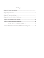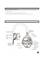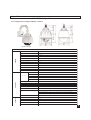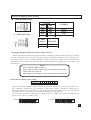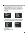
1
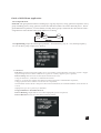
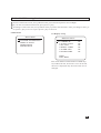
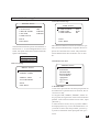
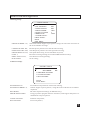
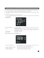
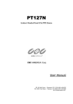
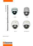
Outdoor Intelligent High Speed Dome Camera User Manuel V D3.31SHAN/2009 Please read this manual carefully before installation and keep it for application Accessories Wall mount bracket Ceiling mount bracket Pole mount bracket Corner mount bracket Joystick controller Connection adopter Catalogue Chapter 1 Product Introduction....................................................................1 Chapter 2 Specification..................................................................................3 Chapter 3 Connection & Setup.......................................................................4 Chapter 4 Protocol & Address Code Setting....................................................6 Chapter 5 User Manual of the Controller........................................................8 Chapter 6 Guide of OSD Menu Application...................................................10 Gudie of Camera Module OSD Menu..............................18 Chapter 7 255 Channels Address DIP Swithch Diagram................19 Product Introduction CHAPTER 1: Product Introduction IR Intelligent high-speed dome camera is one high-tech surveillance & control product with high-reso lution color camera module, omni-direction Pan/Tilt, infrared LED array,multi-functional decoder,CPU processor and memory chip. The product reduces the connection between system components and the installation process, it extremely improve the stability of the system. And it fits different environments no matter indoor or outdoor.7 inch 's profile match with special install mount, arm bracket or ceiling mount can be selected. This dome with weather-proof design, the housing adopts with PC material which is vandalproof,waterproof,aging resistance, anti-acid rain, high temperature resistant and anti-erode. Characteristics: Camera specification: *The speed dome support different integrated camera module including SONY, SANYO. Powerful Pan/Tilt function: *Max. 360 /sec high speed Pan/Tilt turning *Adopted with vector driving technology, Pan/Tilt motions are accomplished in the shortest path. As a re sult, time to target is reduced dramatically and the video on the monitor is very natural to watch. *Super slow speed function can be reached by joystick, the lowest speed can touch 0.05 /sec. Preset, Pattern, Swing, Privacy mask, Group and more function *Up to 128 pieces preset point can be memorized. The additional information such as dwell time,label ... can be set as demand. *Up to 8 pieces point-to-point auto scan can be memorized. Support proportional shift between zoom and speed. *Up to 2 of pattern can be recorded and played back. It can record 200 operation commands. *Up to 5 pieces GROUP can be stored, the function enable the camera to move repetitively with combination of Preset or Pattern or Swing. A group contained with Max.10 presets, patterns or swings. *Max.8 of Privacy masks can be located wherever it is required to protect private life. (Only Sony camera module support this function) *Support Schedule function. PTZ lens control *Max. 1024 cameras can be controlled at the same time by RS-485 bus communication. *Pelco-D, Pelco- P protocol can be selected. OSD Menu * The situation of camera can be displayed on screen with OSD menu function. The detailed camera function also can be set with OSD menu. *The information of camera series number, Pan/Tilt position, alarm in/out, preset all can be shown on screen or not with OSD menu setup; Alarm Function Built-in 4 channels input function. If anyone alarm detector was activated then camera can auto move to preset that beforehand setup. ¡ã ¡ã 1 Product Introduction Convenient installation and operation *With built-in fan & heater and the weather-proof design, the product is very suitable for application in outdoor environment. *The structure of dome camera meets the demand of IP66 standard. *The design concept of high-speed dome and mounting based on convenient installation. Product Diagram 2 Specificaions CHAPTER 2: Specifications 2.1 Configuration of Speed Dome Camera Speed Dome Dimension Product Photo Camera Camera Type & Specifications Sensor 1/4" IT Exview HAD CCD SONY Resolution 480 lines S/N >48db Zoom Ratio 22 times optical zoom; 10 times digital zoom Focal Length F1.6;f=3.9-85.8mm Min. Illumination 0.1Lux Image Freeze Yes Day/Night Yes Focus Auto/Manual Iris Auto White Balance Auto BLC ON/OFF selectable by OSD menu. Turning Scope Pan 360° ;Tilt 90° Preset 360°/Sec Manual 0.025°~120°/Sec Swing Speed 200°/Sec Pan/Tilt Auto Scan 15°/Sec~60°/Sec Preset Quantity 128 Pattern 2 Patterns,200 commands every one Swing 8 Group 5 Groups and each with 10 actions Protocol Pelco-D; Pelco-P;VC;WORLD Suport camera module setup and speed pan/tilt setup OSD Programmable OSD for Pan/Tilt,Zoom camera, Swing, Pattern, Group, Schedule... Functions. Fan/Heater Others Temperature Built-in auto controler heater and fan -35°C~50°C Moisture <95% Power Supply AC24V Consumption 20W Heater Consumption 10W 3 Connection & Setup CHAPTER 3 Connection & Setup 3.1 Intelligent speed dome camera connection diagram 3.2 Cable connection; Please check carefully the voltage and current capcity of the electrical power source. The correct power to operate the camera is AC24V / 1.5A; There is one AC24V, 3A PSU in the packing carton of speed dome camera. We suggest you to use this PSU to power supply the speed dome camera. If the power is not enough, the camera can not work properly. The BNC connector can be connected to video coaxal cable directly for vide signal transmission. Please check the polarity of Rs485 cable before installation. If the Rs485 cables be connected reversed, the camera can not get any response from controller. Notices: We suggest you select twisted cable which the copper wire diameter more than 0.25mm. And if the transmission distance more than 700 feet, we suggest you to select one Rs485 signal amplifier. Or the Rs485 contral may not work properly. 4 Connection & Setup RS485 Bus marching resister To the application of system center control, in order to prevent the reflection and interference of RS485 signal and other communication signals, the communication port of farthest equipment from control center should parallel connected with one marching resister. 3.3 RS-485 match resistance application In order to get one good RS485 control, to avoid the reflection and disturbance of RS485 communication signal or other signal, one terminal match resistance is needed on the last dome camera. Please make the ten switch dail to “ ON “ on the b ack panel. Controller RS-485 terminal match resistance ON Terminal match resistance OFF Terminal match resistance OFF Terminal match resistance OFF Notice Please make sure the dome connects into voltage,use the accessory power. Please make sure the anode and cathode of RS-485 accurate to avoid the dome can not be controlled. 5 Protocol & Address Code Setting Chapter 4 Protocol & Address Code Setting Before installation, please check the Communication Protocol, Baud Rate and Address Code of the control main machine in the system. There are two groups dip switch which be used to set protocol, baud rate and address of dome camera. Please set the dip switch consistent with system. u The disassemble way of transparent dome: u Fix screws 4-1. Protocol and baud rate setup of high speed dome camera u Protocol & baud rate setup: SWITCH PRO0 (Pin 1) PRO1 (Pin2) PRO 2 (Pin 3) Protocol/Baud Rate OFF OFF OFF PELCO-D, 2400bps ON ON OFF PELCO-P, 9600bps 6 Protocol & Address Code Setting u Camera module setup: ON/OFF ZM0 ZM1 (Pin 4) (Pin 5) OFF OFF ON OFF OFF ON ON ON 1. NTSC/PAL setup: NT/PAL (Pin 6) NTSC/PAL OFF ON NTSC PAL CAMERA SONY YOKO CNB LG Intelligent High Speed Dome Camera Address Setup Before the application of high speed pan/tilt dome, the address code should be setup firstly. The address code is decided by the 8 bits dip switch on back panel which adopted with 8421 code. Support up to 255 pieces addresses. ON is respected by number 1. OFF is respected by number 0. Please check the attached address list at the back side of manual for the detailed setting way (Refer Chapter 10: Address code DIP diagram) . Notice Factory default address code is 1. Please make sure dip switch is on position, otherwise,the dome camera will out of control. Please make sure the dome can be controlled before installation. The method of address code setup Serial No. Address Code st ¡ Dip switch has defined address number for each bit, as above diagram: No.1 stands for 1 address No., No.2 stands for 2 nd address No., No. 3 stands for 4 th address No., and No. 4 stands for 8 th address No. , how many channels you would like to set, just dip the relevant serial number to “on”. You can plus existing address bits., to get what you can not find from the dip switch diagram. I.e. If you want to dip the 1 st address No, just dip serial No. 1 to “ON”. If you want No.37 address, just dip No.1, No.4, No.32 to “ON” position . 1 Channel 37 Channels 7 User Manual of The Controller Chapter 5:User Manual of The Controller All the functions of IR high speed dome camera can be achieved through the control by keyboard. Because the detailed operation from different company is different, if the control system is from other comp any,please control the dome according to the instruction from control system supplier. Some special functions of high speed dome ask special operation , please connected with the control system supplier for detailed operation way. (We suggest choosing our controller with dome camera that can help you to get more function) For the following description, control way is the same, no matter what protocol to be selected. Like PlecoD, Pelco-P ! 5.1 Communication Protocol Selection After connection of all together, the communication protocol selection will be show on the screen when you press ”F4”. The protocol definition as bellow: “Pelco-P” “Pelco-D” PELCO P protocol PELCO D protocol 9600bps 2400bps The above definition is the switchover order for communication protocol according to the order of pressing on the “F4” key . 5.2 Camera Selection Selecting any camera: Just input [255] address number, then input [CAM]. Selecting next camera: Input [+1], then the next camera be selected. Selecting last camera: Input [-1], then the last camera be selected. I.E. To Select No.2 camera: Input [2], then input [CAM], the No.2 camera be selected; After No.2 camera be selected, input [+1], the No.3 camera be selected; If we want to select No.1 camera after NO.2 camera be selected, just input [-1], then the No.1 camera be selected; 5.3 P/T/Z Control Input the camera series number which one you want to control. Input [ZOOM+], [ZOOM-], [FOCUS+],[FOCUS-] or just move the joystick to control pan/tilt and lens control I.E. Control No.2 P/T/Z camera: Input [2] + [CAM], then using joystick to move pan/tilt to the wanted position------input [ZOOM+], [ZOOM-], [FOCUS+],[FOCUS-] to control dome camera. 5.4 Setup of P/T/Z Preset Points: Select wanted camera, then use joystick to move the camera to appointed position. Input [F1] + [8]; Input you wanted series number for this preset point ( from 1 128 ); Input [ PRE], then one preset point be established. 8 User Manual of The Controller I.E. To establish No.15 preset point on No.5 camera: Input [5] + [CAM] to select No.5 camera firstly.Zoom out lens then use joystick to move camera to wanted position. Input [F1] + [15] + [PRE] If want to establish different preset point, just change another series number, repeat the above operation. 5.5 Preset Point Call Back (1) Manual Control: Input the camera address number which one you want to control; Input preset point number ( 128), the default number is 1. Input [CALL], the wanted preset point be called back; I.E. To call the No.6 preset point back on No. 3 camera: Input [3] + [CAM] + [6] + [CALL], then the No.6 preset point on No.3 camera be called back. (2). Automatically Control: Input the camera address number which one you want to control; Input the largest preset point number (2-16) which want to be automatically controlled, the default number is 8. The number of automatically controlled preset point can be different with different P/T/Z camera, but the largest automatically control number is 16. Input [RUN]; Revising the dwell time on preset point Input the new dwell time (160), then input [DWL], after that the dwell time on all preset point be changed from 1 second to 60 second. I.E. To automatically control the top 10 preset point on No.7 camera,the dwell time is 20 seconds: Input [7] + [CAM] to select camera, input [10] + [RUN], input [20] + [DWL], then the top 10 preset point be called back automatically, dwell time is 20 second. (3). Termination of Preset Automatically Control: To select you want to controlled camera; Input [HOLD] or just move the joystick to stop automatically turning with this camera. Other camera won't be affected; I.E. To stop the automatically control on No.4 camera: Input [4] + [CAM], then input [HOLD] or just move the joystick, the automatically preset control on No.4 camera be terminated. 5.6 Deletion of Mistake Operation: Input [DEL] can clean the input item on screen. If any mistake with input, just input [DEL] to clean. If controller without “SAL” function key, it can realize the Pattern, Swing and group function through call back relevant preset, the details as bellow: 2 patterns use from “131” to “132” preset to operate the patterns which have been setup. 8 Swings using from “141” to “”148 preset to operate the swings which have been setup 5 Groups use from “151” to “155” preset to operate the swings which have been setup.. 9 Guide of OSD Menu Application CHAPTER 6: Guide of OSD Menu Application Checking before Operation: Checking the cable connection carefully before camera be powered; The camera address ID of the controller must same of the camera address ID. The camera ID can be checked by reading DIP switch on PCB of camera. If your controller supports multi-protocols, the protocol must be adjusted to the same as camera protocol. The protocol changing on camera by DIP switch will come into work after camera restart. Since the operation methods are different from different suppliers. Generally the operation of controller should base on the manual from the manufacturer of controller. Some special function of our high speed dome camera can't be operated by other manufacturer's controller. There are some special demands and operations at some times, please connect with the dealer or manufacturer of you selected controller. Since preset 95 is used to start the OSD menu, so it can't be used as regular preset. Therefore, the description “ Presets 1~128 always means excluding Preset 95 in this manual ” Self-Checking Information: OSD Menu: 1.Function: With the application of OSD menu, Preset, Swing, Group, Pattern, Alarm I/O and other functions can be setup for application. Input [95] --- [CALL] to begin the application of OSD menu . 10 Guide of OSD Menu Application Using joystick to move the cursor then input [FOCUS+] to selection wanted item. SYSTEM INFORMATION selection is used to check system version information. DISPLAY SETUP selection is used to setup what be shown on screen. DOME SETUP selection is used to setup all functions of speed dome camera. It is the main function selection. EXTRA SETUP selection is used to setup unimportant setup of speed dome 1. DOME SETUP: Please using joystick to move cursor to DOME SETUP selection. Then input [FOCUS+] , the manu com e into the sub-manu as shown on followed: 1.1 SETUP CAMERA: This selection be used to setup the specifications of camea module. With the selection, the camera functions of DIGITAL ZOOM, FOCUS MODE, BACK LIGHT, DAY/NIGHT, AWB, SHARPNESS, IRIS MODE, RESET CAMERA , CAMERA FLIP and PICTURE FREEZE can be setup 1.2 SETUP MOTION: This selection mainly be used to setup the specifications of the movement of speed dome camera. AUTO FLIP, MOTOR SPEED, PARK POSITION can be setup by this selection. 11 Guide of OSD Menu Application 1.3 Preset: Function: Up to 127 pieces preset can be set. Beside No.95, all presets can be named as 1---128. With the combination of preset key and number key of controller, the preset point setup and call back function can be quickly operated. And modify the default preset information. ( preset label, dwell time……) Setup of Preset Point: Select camera, move camera to wanted position. Input [F1]---[8]---[preset number]---[PRE] Preset Point Call Back: Input wanted preset number (default is 1), input [CALL], then the preset point be called back. Preset Deletion: Please use the preset OSD menu to delete preset, or just setup another preset with the sAme number to cover the old preset point; The PRESET NO selection be used to setup the preset point series number. This series number can be shown on screen. The PRESET LABEL is used to edit the name of preset point. The DWELL TIME selection is used to setup the stop time on preset point of camera. Using joystick to move cursor to select wanted letter, then input [FOCUS+] to confirm. The CLEAR PRESET selection is used to clear preset point. 1.4 SWING SETUP: This selection is used to setup the swing movement of speed dome camera With this function, the speed dome camera can move between two preset points. Swing Running: Put swing number and add 10(11-18).then in [SAL]; 12 Guide of OSD Menu Application 1.5 Group Function: Function: The group function allows running up to 5 groups of preset, swing, pattern in sequence. Every group including preset, swing, pattern, but the total function number can't more than 200 pieces. Through the OSD menu operation, we can establish, modify, delete groups. The dwell time which be set with swing function still workable when group function is working. Group Running: Input the wanted group number + 20 numeric key ( say 21---25), then input [SAL]. I.E. To run No.5 group: Input [25]---[SAL];. 1.6. Pattern: Function: The pattern function enables us to save and play camera motions created by joystick. Support up to 200 pieces movement command every pattern. Totally support 2 pieces pattern; Pattern Setup : Pattern can be created by the followed two ways: Using the numeric 1,2 and SAL to establish one Pattern: Input [1---2], then press [SAL] more than 2 seconds to begin one establishment of pattern; Using joystick to move camera to create the trace of pattern; The limitation of movement is 200 pieces movement commands, the command number can be shown on screen; Input [Focus+] to save, [Focus-] to abandon; Using OSD Menu to Establish Pattern: Pattern Running: Input numeric 1or 2 then input [SAL] to run one pattern; Pattern Deletion: Please use OSD menu to delete pattern; 10 14 Guide of OSD Menu Application 6.Other Functions: Information protection after power off: This function can get back the last automatically running action. Beside manual operation, preset, swing, trace recording, pattern all can be get back. 180 auto flip function: If the vertical turning of camera more than 90 camera can automatically 180 turning at horizontal direction. Then camera can continuously tracing objection. Park Function: With this function, camera can automatically turn to one special position to rectify mistake which be accumulated through automatic turning. ( Normally, the park position is No.1 preset point); If the camera is not operated for a while, the camera also can turn to park position automatically. The waiting time of park position is adjustable from Privacy Zone Masking : ( SONY camera module only) In order to protect privacy, the speed dome camera support 8 pieces masking zone to hide objections such as windows, shops or private space ….! ¡ã ¡ã ¡ã 7. OSD Display of Main Screen Date,time table Camera No Action title X010 ID:001 P/T/Z angle and Alarm info zoom information P/T angle and Zoom information : To show the Pan/Tilt position and zoom magnification; Camera ID: The current camera address number. Action Title: Followings are possible Action Titles and their meaning. “SPRESET~ ”: When preset ~ is stored “PRESET ~” : When camera reach to Preset ~ “UNDEFINED”: When undefined Preset number is called to move “SWING ~”: When swing ~ is in action Preset Label : The label stored for specific preset point. Alarm Input: The has 4 channels input .If anyone point is ON state it will show a number corresponding to each point.If the point is OFF state, ”-” will be displayed. 8. Major Rules of Menu Operation The menu items surrounded with ( ) always has its sub menu. For all menu level, to go into sub menu, press [Focus+] key, to go up to upper menu, press [Focus] key. If you learn by heart a rule that F+ is always similar to ENTER key and [Focus-] key is always ESC key, many other functions of these keys will be easy to understand. 10 13 Guide of OSD Menu Application To move from item to item, use Up/Down of the joystick in the Up/Down or Left/Right. If you want to confirm a menu item, press [Focus+] key. To change a value of an item, use Up/Down of the joystick in the controller. After you change a value, press [Focus+] key to save it or press [Focus-] key to cancel it. 9.Main menu 10. Display Setup MAIN MENU 1.SYSTEM INFORMATION 2.DISPLAY SETUP 3.DOME SETUP 4.EXTRA SETUP DISPLAY SETUP 1.CAMERA ID 2.ACTION TITLE 3.PTZ INFO 4.PRESET LABEL 5.ALARM INFO 6.SYSTEM TIME ON ON ON ON ON ON BACK EXIT MENU This menu defines Enable/Disable of OSD display on Main Screen. If an item is set to be AUTO, the item is displayed only when the value of it is changed. 10 13 Guide of OSD Menu Application 12.PTZ Motion setup 13.Park Action Setup MOTION SETUP PARK SETUP 1.REBOOT ACTION 2.AUTO FLIP 3.MOTOR SPEED 4.JOG DIR 5.PARK SETUP ON OFF NORMAL NORMAL 1.PARK ENABLE 2.PARK TIME 3.PARK PRESET OFF 00:05 001 BACK EXIT MENU BACK EXIT MENU The maximum manual speed is listed below when zoom is *1. As zoom magnification is increased, the speed will be decreased to maintain equal controllability. High speed 0 ° ~180 ° /sec Middle speed 0 ° ~90 ° /sec Low speed 0 ° ~90 ° /sec This function enables to locate the camera to specific position automatically if operator doesn't operate the controller for a while. The park Time can be defined as an interval from 1 min. to 4 hours. 15.Edit Preset Label 14.Preset Setup PRESET SETUP PRESET SETUP 1.PRESET NO 2.PRESET LABEL 001 3.DWELL TIME 4.CLEAR PRESET 3 BACK EXIT MENU LABEL FOR PRESET 0123456789 ABCDEFGHIJ KLMNOPQRST UVWXYZabcd efghigklmn opqrstuvwx yz-/-;,.- 001 LAB FOR PRE: 1.The cursor presents the current input position of the label letter.Upon the letter be selected , the cursor move to left. 2.Using the “UP”,” DOWN ”,”R IGHT ”,”L EFT ” of the joystick, the right letter can be selected from alphabet . After selection of the correct letter, input [FOCUS+]. 3.After all letters be set, move joystick to “OK” then input [FOCUS+] to save the modification . If you want to cancel the setup of label, just move joystick to “C ANCE L” then input [FOCUS+] to cancel. 10 14 Guide of OSD Menu Application 16.Swing Setup: SWING SETUP 1.SWING NUMBER: 2.1ST POSITION: 3.2ND POSITION: 4.SWING SPEED: 5.LOOP COUNTER 6.DIRECTION: 7.CLEAR SWING: 8.RUN SWING: BACK EXIT MENU 1 001 001 30d/s 3 LEFT SWING NUMBER: 1/8; This P/TZ camera support up to 8 pieces swing scan. This item is used to set the series number of swings. L POSITION: PRE 001; The 001 preset point be set as the left side of swing; R POSITION: PRE 002; The 002 preset point be set as the right side of swing; SWING SPEED: AUTO; The speed dome swing. AUTO is default of system; LOOP: 1; The times of swing turning ( be used for GROUP function only) DIRECTION: AUTO; The direction of swing turning; RUN SWING To run swing; 17.Pattern Setup: PATTERN SETUP 1.PATTERN NUMBER: RECORDER: 2.PROGRAM PATTERN 3.CLEAR PATTERN 4.RUN PATTERN 1/2 000 BACK EXIT MENU PATTERN SETUP: PATTERN NUMBER 1/2; RECORDER; PROGRAM PATTERN: CLEAR PATTERN: RUN PATTERN: To establish one pattern for camera auto turning; Camera support 2 pieces pattern, using this item to edit the series number of pattern; The times of pattern turning ( for GROUP only); Using joystick to program the trace of camera, total support 500 pieces commands for one piece pattern. To delete one pattern; To run one pattern; 10 15 Guide of OSD Menu Application l Using joystick to move camera to wanted beginning position, and adjusting lens to suitable zoom times, input [FOCUS+] to begin recording, or input [FOCUS-] to abandon. l The recording support up to 200 pieces movement command. The total recording number be shown on screen. l The zoom changing of camera also be recorded; At any time through recording, input [FOCUS+] to record pattern. Input [FOCUS-] to abandon pattern recording. 18.Group Setup: GROUP NUMBER: 1/5 Setup: CLEAR GROUP: RUN GROUP: The camera support 5 pieces group function; This item be used to set one series number of group; “X000” mean the function still not be selected; If preset be selected, will show “P1-P128” ; If swing be selected, will show “S1-S5” ; If pattern be selected, will show “T1-T4”; To cancel the group setup; To run group; 19.Privacy Setup ( SONY camera module only) PRIVACY NUMBER: 1/8 PRIVACY ENABLE: ON/OFF PRIVACY WIDE: 000 PRIVACY HIGH:000 Support 8 pieces privacy zone masking. This item be used to set one series number of every privacy masking zone. This item be used to enable masking to work or not; To setup the width of masking zone(1-999); To setup the height of masking zone(1-999); 10 16 Guide of OSD Menu Application After the setup of masking of privacy zone, when you move the camera to this position, you will find this zone already be covered by masking. The series number of masking will be shown at the center of masking. Totally support 8 pieces privacy zone masking. Please notices: Sometimes, because of the lower speed of screen showing and the Min. illumination is decided by the size of signal character, may lead to position mistake. Notice The size of privacy zone masking will be changed according to the zoom changing of camera lens 20. Schedule Setup SCHEDULE PROGRAM 1.00:00 X001 X001 X001 2.00:00 X001 X001 X001 3.CLEAR ALL 4.SCHDULE ENABLE OFF BACK EXIT MENU “X000” mean the action which still not be selected; If the preset be selected, will show “P1~P128” ; If swing be selected, will show “S1~S5”; If pattern be selected, will show “T1~T4” ; If group be selected, will show “G1~G8”. The keeping time, from 1 to 120 minutes; CLEAR ALL Delete schedule SCHUDULE ENABLE Schedule function switch ON/OFF 17 Guide of Camera Module OSD Menu We supply one special function with our P/T/Z dome camera----------the camera module OSD menu operation. You can input [96] + [CALL] to setup camera module OSD menu. Using [ZOOM+] and [ZOOM-] to move the cursor Using [FOCUS+] and [FOCUS-] to select the parameter of camera module Notice: The camera module parameters already be setup well before be shipped out of factory. We do not suggest you change the parameters beside special demand. 18 17 Address DIP Switch Setup Digram CHAPTER 10:255 CHANNELS ADDRESS DIP SWITCH DIGRAM ON OFF 1 1 2 3 4 5 6 7 8 9 10 1 2 3 4 5 6 7 8 9 10 1 2 3 4 5 6 7 8 9 10 4 1 2 3 4 5 6 7 8 9 10 5 1 2 3 4 5 6 7 8 9 10 6 1 2 3 4 5 6 7 8 9 10 7 1 2 3 4 5 ON OFF 2 3 8 ON OFF ON OFF ON OFF ON OFF ON OFF 6 7 8 9 10 ON OFF 1 2 3 4 5 6 7 8 9 10 1 2 3 4 5 6 7 8 9 10 1 2 3 4 5 6 7 8 9 10 1 2 3 4 5 6 7 8 9 10 1 2 3 4 5 6 7 8 9 10 1 2 3 4 5 6 7 8 9 10 1 2 3 4 5 6 7 8 9 10 1 2 3 4 5 6 7 8 9 10 1 2 3 4 5 6 7 8 9 10 1 2 3 4 5 6 7 8 9 10 1 2 3 4 5 6 7 8 9 10 1 2 3 4 5 6 7 8 9 10 1 2 3 4 5 6 7 8 9 10 1 2 3 4 5 6 7 8 9 10 1 2 3 4 5 6 7 8 9 10 ON OFF 9 ON OFF 10 ON OFF 11 ON OFF 12 ON OFF 13 ON OFF 14 ON OFF 15 ON OFF 16 ON OFF 17 ON OFF 18 ON OFF 19 ON OFF 20 ON OFF 21 ON OFF 22 ON OFF 23 1 2 3 4 5 6 7 8 9 10 1 2 3 4 5 6 7 8 9 10 1 2 3 4 5 6 7 8 9 10 26 1 2 3 4 5 6 7 8 9 10 27 1 2 3 4 5 6 7 8 9 10 28 1 2 3 4 5 6 7 8 9 10 29 1 2 3 4 5 ON OFF 24 25 30 ON OFF ON OFF ON OFF ON OFF ON OFF 6 7 8 9 10 ON OFF 1 2 3 4 5 6 7 8 9 10 1 2 3 4 5 6 7 8 9 10 1 2 3 4 5 6 7 8 9 10 1 2 3 4 5 6 7 8 9 10 1 2 3 4 5 6 7 8 9 10 1 2 3 4 5 6 7 8 9 10 1 2 3 4 5 6 7 8 9 10 1 2 3 4 5 6 7 8 9 10 1 2 3 4 5 6 7 8 9 10 1 2 3 4 5 6 7 8 9 10 1 2 3 4 5 6 7 8 9 10 1 2 3 4 5 6 7 8 9 10 1 2 3 4 5 6 7 8 9 10 1 2 3 4 5 6 7 8 9 10 1 2 3 4 5 6 7 8 9 10 ON OFF 31 ON OFF 32 ON OFF 33 ON OFF 34 ON OFF 35 ON OFF 36 ON OFF 37 ON OFF 38 ON OFF 39 ON OFF 40 ON OFF 41 ON OFF 42 ON OFF 43 ON OFF 44 ON OFF 45 1 2 3 4 5 6 7 8 9 10 1 2 3 4 5 6 7 8 9 10 1 2 3 4 5 6 7 8 9 10 48 1 2 3 4 5 6 7 8 9 10 49 1 2 3 4 5 6 7 8 9 10 50 1 2 3 4 5 6 7 8 9 10 51 1 2 3 4 5 ON OFF 46 47 52 ON OFF ON OFF ON OFF ON OFF ON OFF 6 7 8 9 10 ON OFF 67 1 2 3 4 5 6 7 8 9 10 1 2 3 4 5 6 7 8 9 10 1 2 3 4 5 6 7 8 9 10 70 1 2 3 4 5 6 7 8 9 10 71 1 2 3 4 5 6 7 8 9 10 72 1 2 3 4 5 6 7 8 9 10 73 1 3 4 5 8 6 9 7 108 9 ON OFF 68 69 ON OFF ON OFF ON OFF ON OFF ON OFF ON OFF 1 2 3 4 5 6 7 8 9 10 1 2 3 4 5 6 7 8 9 10 1 2 3 4 5 6 7 8 9 10 1 2 3 4 5 6 7 8 9 10 1 2 3 4 5 6 7 8 9 10 1 2 3 4 5 6 7 8 9 10 1 2 3 4 5 6 7 8 9 10 1 2 3 4 5 6 7 8 9 10 1 2 3 4 5 6 7 8 9 10 1 2 3 4 5 6 7 8 9 10 1 2 3 4 5 6 7 8 9 10 1 2 3 4 5 6 7 8 9 10 1 2 3 4 5 6 7 8 9 10 1 2 3 4 5 6 7 8 9 10 1 2 3 4 5 6 7 8 9 10 ON OFF 53 ON OFF 54 ON OFF 55 ON OFF 56 ON OFF 57 ON OFF 58 ON OFF 59 ON OFF 60 ON OFF 61 ON OFF 62 ON OFF 63 ON OFF 64 ON OFF 65 ON OFF 66 ON OFF 251 1 2 3 4 5 6 7 8 9 10 1 2 3 4 5 6 7 8 9 10 1 2 3 4 5 6 7 8 9 10 1 2 3 4 5 6 7 8 9 10 1 2 3 4 5 6 7 8 9 10 ON OFF 252 ON OFF 253 ON OFF 254 ON OFF 255 10 19 10 20 IR IR PAN DEL 9 OR OR Keyboard - + S- S+ IS IS CU FO AUX2 PRE 6 0 CU FO MSK CALL ACX AUX1 3 MON 8 2 5 1 7 4 - + OM OM ZO ZO CAM F4 -1 +1 F2 F1 F3 SAL HOLD RUN DWL More 485 Bus Control device DVR Hard disk video 485turn232 AB Line Code Divider High Speed Dome P/T/Z Decoder Pan B A K ey b oa r d OR D V R 1# Dome plate A B 3# A B Connection Sketch Map 2# A B N# A B Our company product standard connection is series connection device P/T/Z 1 5 00 m RS-485 Bus Control Mode Device Connection Sketch Map