1
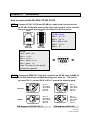
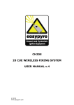
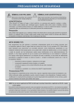
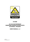
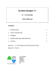
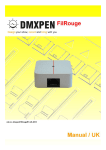
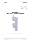
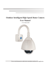
ISO 9001 CERTIFIED
www.liteputer.com.tw
Architectural & Environmental
Lighting Control System
【User manual】
Lite-Puter Enterprise Co., Ltd.
Website: www.liteputer.com.tw
E-mail: [email protected]
LITE-PUTER
CP-3B [EUM-E]
Index
Chapter 1. Lite-Puter Environmental Lighting Control System ................... 2
Chapter 2. Installation
.................................................................................................................... 4
Chapter 3. The functions of CP-2B/CP-3B
3-1 CP-2B ................................................................................... 6
3-2 CP-3B ................................................................................... 7
Chapter 4. The operation of CP-3B
4-1 Channel
1. How to set the dimming level of each channel........................... 9
2. How to set the dimming level of a series of channels. ............. 10
3. How to display the dimming level of the channel. .................... 11
4. How to modify the dimming level of channels.......................... 11
4-2
Scene
1. How to save the dimming level of each channel in a scene .... 12
2. How to set timer function of scene........................................... 13
3. How to execute or cancel timer function of scene ................... 14
4. How to check the timer function of scene. ............................. 14
5. How to cancel timer function of scene ..................................... 15
6. How to set fader function ......................................................... 15
7. Corresponding list of fader time............................................... 16
8. How to call out “scene 0---scene 9” by special key ................. 17
9. How to call out the “scene 10---scene 99” ............................... 17
4-3
Blind
1. How to modify and set any scenes
without influencing the current scene ............................ 18
2. How to modify the dimming level of all channels
in the current scene .................................................... 20
4-4
Timer
How to set hours and minutes in the led...................................... 21
4-5
Special functions for emergency situations
1. How to turn off all the lights immediately.................................. 22
2. How to increase all the dimming level of the current scene ... 22
3. How to decrease all the dimming level of the current scene.... 22
4. How to lock and unlock the function key.................................. 22
Chapter 5. DP-6B / DP-6S
5- 1 Feature & specifications .................................................... 23
5- 2 Installation ............................................................................... 25
5- 3 Operation .................................................................................. 27
Chapter 6. DP-11
6- 1 Feature & specifications .................................................... 33
6- 2 Operation .................................................................................. 34
1
Lite-Puter
CP-3B [EUM-E]
Chapter 1. Lite-Puter Environmental Lighting Control System
“Lite-Puter Environmental Lighting Control System”use degital panel
《CP-2B / CP-3B》 to connect with DMX decorder DP-6 and DX-1220, the
dimmer pack. This system can be used in environmental lighting control
system to control the lighting atmosphere in each room or public area, such
as: hotel, fair, conference, hall, department store and entertainment center etc.
CONTROL PANEL
DX-1220
CP-3B
DMX PLUG-IN DIMMER PACK
P-27 PACK
AC TRIG
P-27 PACK
AC TRIG
P-27 PACK
AC TRIG
P-27 PACK
AC TRIG
P-27 PACK
AC TRIG
P-27 PACK
AC TRIG
P-27 PACK
AC TRIG
P-27 PACK
AC TRIG
P-27 PACK
AC TRIG
P-27 PACK
AC TRIG
P-27 PACK
AC TRIG
P-27 PACK
AC TRIG
V1
V2
LOADS
V3 DMX
FIRST CH.
CAN
SEL
SET FNC MODE
CP-2B
0-10VDC
ANALOG I N
P
DMX
OUT
U
DMX
IN
S
ON
TERMINATE
H
AC TRIG
P-27 PACK
AC TRIG
P-27 PACK
AC TRIG
P-27 PACK
AC TRIG
P-27 PACK
AC TRIG
P-27 PACK
AC TRIG
P-27 PACK
AC TRIG
P-27 PACK
AC TRIG
P-27 PACK
AC TRIG
P-27 PACK
AC TRIG
P-27 PACK
AC TRIG
V1
V2
V3 DMX
LOADS
S
H
AC TRIG
P-27 PACK
FIRST CH.
DMX OUT
DMX OUT
DP-11 DMX PATCH INTERFACE
1
3 2
5
3
DMX IN
DMX OUT
PIN 1: G
PIN 2: DATAPIN 3: DATA+
PIN 4: NC
PIN 5: NC
SEL
SET FNC MODE
POWER
0-10VDC
ANALOG I N
DMX OUT
PIN 1: G
PIN 2: DATAPIN 3: DATA+
PIN 4: NC
PIN 5: NC
DMX
OUT
U
DMX OUT
PIN 1: G
PIN 2: DATAPIN 3: DATA+
PIN 4: NC
PIN 5: NC
4
ETR
5
FUNC.
4
DISPLAY
2
3
2
CAN
U
R
POWER
P
1
DMX OUT
PIN 1: G
PIN 2: DATAPIN 3: DATA+
PIN 4: NC
PIN 5: NC
1
1
3 2
4
5
ETR
5
FUNC.
4
DISPLAY
P
DP-6 DMX INTERFACE
U
R
P
RS-485
S
H
P-27 PACK
DMX
IN
DMX IN
S
ON
TERMINATE
H
DP-6B
DMX DECODER
DP-11
DMX PATCH PANEL
12CH.
20A per channel
RS-422
P-27 PACK
AC TRIG
P-27 PACK
AC TRIG
P-27 PACK
AC TRIG
P-27 PACK
AC TRIG
P-27 PACK
AC TRIG
P-27 PACK
AC TRIG
P-27 PACK
AC TRIG
P-27 PACK
AC TRIG
P-27 PACK
AC TRIG
P-27 PACK
AC TRIG
P-27 PACK
AC TRIG
P-27 PACK
AC TRIG
V1
V2
LOADS
V3 DMX
FIRST CH.
CAN
SEL
SET FNC MODE
0-10VDC
ANALOG I N
P
DMX
OUT
U
DMX
IN
S
ON
TERMINATE
H
Lite-Puter’s Architechtural & Environmental Lighting Control System
CP-2B DMX Control Panel :
It is easy to call out Scene1 ~ Scene6、OFF to meet your needs ( each button has
programmed different dimming levels which is called “scene”). You can also control
the same area by connecting several pieces of CP-2B (multi-control points) or
control independently when one area is separated into small sections. ( 8 sections
max. for 1 DP-6, 16 sections max. for 2 DP-6, etc… ).
CP-3B DMX Control Panel :
You can set / call out the dimming level and the time of changing scene in each area.
You can also control the same area by connecting several pieces of CP-3B
(multi-control points) or control independently when one area is separated into small
sections. ( 8 sections max. for 1 DP-6, 16 sections max. for 2 DP-6, etc… ).
2
Lite-Puter
CP-3B [EUM-E]
DP-6 DMX Decoder :
It controls 256 channels, stores 100 scenes. It has the timer functions for
automatically executive scenes according to the schedule that has been set.
DP-11 DMX Patch Setting Panel :
This unit is for DMX soft patch, you can change the dimming channel without
change the wiring.
DX-1220 DMX Plug–In Dimmer Pack :
Each module can be removed easily, 20A per channel can be set dimming or
switching for different kind of loads.
You cannot set scene by CP-2B, but CP-3B (or use other DMX console). If
you save the data in DP-6, and then take away CP-3B, you can still call out the
data saved in DP-6 by CP-2B.
3
Lite-Puter
CP-3B [EUM-E]
Chapter 2.
Installation
How to connect with DP-6B & CP-3B/ CP-2B
STEP-1: Connect CP-2B / CP-3B and DP-6B by a cable from 6 pin phone jack
on CP-3B/ CP-2B back panel to the 9 pin d-type plug & socket on cable
side are reversed, please check pin indictor on the connector.
SOCKET
123 4 56
PLUG
CP-2B / CP-3B
PIN 1: DC 12V
PIN 2: DATA PIN 3 - PIN 4: GND
PIN 5: DATA +
PIN 6: NC
123 4 56
DP-6B
PIN 1 ~ PIN 2: GND
PIN 3: DATA PIN 4: DATA +
PIN 5 ~ PIN 6 : DC12V
PIN 7 ~ PIN 9: NC
5 4 3 2 1
9 8 7 6
Note: The order of 9 pin plug &
sockets are opposits.
STEP-2: Connecting DMX OUT 5 pin XLR connector on DP-6B panel to DMX IN
5 pin XLR connectors on DMX dimming pack. Such as: DX-1220. If
DMX IN
PIN 1: G
PIN 2: DATAPIN 3: DATA+
PIN 4: NC
PIN 5: NC
PIN 1: G
PIN 2: DATAPIN 3: DATA+
PIN 4: NC
PIN 5: NC
PIN diagram of DP-6B / DP-11
PUSH
DMX OUT
PUSH
you have DP-11, connect DP-6 to DP-11, than to the dimming pack.
PIN 1: G
PIN 2: DATAPIN 3: DATA+
PIN 4: NC
PIN 5: NC
PIN 1: G
PIN 2: DATAPIN 3: DATA+
PIN 4: NC
PIN 5: NC
PIN diagram of DX-1220
4
Lite-Puter
CP-3B [EUM-E]
P-27 PACK
AC TRIG
P-27 PACK
AC TRIG
P-27 PACK
AC TRIG
P-27 PACK
AC TRIG
P-27 PACK
AC TRIG
P-27 PACK
AC TRIG
P-27 PACK
AC TRIG
P-27 PACK
AC TRIG
P-27 PACK
AC TRIG
P-27 PACK
AC TRIG
P-27 PACK
AC TRIG
P-27 PACK
AC TRIG
V1
V2
CAN
V3 DMX
SEL
SET FNC MODE
DMX
OUT
DMX
IN
Remark: The instruction of using twisted pairs
WHITE
RED
GREEN
BLACK
SILVER
Al-Myler shielded twied pair
24AWG
CAUTION :
(1) Always use the same twisted pair for "DATA -" and "DATA +".
(2) In the illustration, the red wire and the white one are a pair, the green and
black are the other. Color is not the point but do use the same twisted pair.
(3) Use another twisted pair for DC12V power input.
(4) The ground (silver) must be connected to the chassis of DP-6B
RED .......................... DATA +
WHITE ...................... DATA GREEN ..................... DC 12V +
BLACK ...................... GND
SILVER ..................... GND
5
Lite-Puter
CP-3B [EUM-E]
Chapter 3.
The functions of CP-2B/CP-3B
3-1 CP-2B
l One touch to call out any of 7 scenes ( S1-S6 & OFF) that were preset.
l 256 steps of dimming resolutions.
l Memories are protected by backup battery of DP-6B, and the last
scene will be recalled automatically after ther recover of electric
power failure.
1 ~ 6 SCENE 1 ~ SCENE 6
7 OFF
8 ▲ INCREASE THE DIMMING LEVEL.
9
P.S. Uuder any circumstances, press this key to increase the dimming level
of current scene up to 100% without changing the memory, and the
memories of S1~S6 wouldn't be changed.
▼ DECREASE THE DIMMIGN LEVEL
P.S. Uuder any circumstances to press this function key can make lighting
level of all channels gradually reduced until full-off , and the memories of
S1~S6 wouldn't be changed.
10
11
12
DISPLAY THE CURRENT SCENE.
DISPIAY THE CURRENT TIME.
DISPLAY THE CURRENT TIME.
6
Lite-Puter
CP-3B [EUM-E]
3-2
CP-3B
l
l
l
l
l
l
l
100 scenes memories. 256 control channels output.
Set the time of fade in and fade out.
Timer function.
Blind function: to modify the data of any scenes without changing
the output of the current scene.
Keyboard lock / unlock function.
256 steps of dimming resolutions.
Memories are protected by backup battery.
Operation: 【FUNC】+【1】 means holding “FUNC” key and press no. “1”
key at the same time.
7
Lite-Puter
CP-3B [EUM-E]
Displsy & Key
operation
FUNCTION
(1) In time mode:display the current time.
(2) In channel mode:display the dimming level of the
current channel.
(3) In scene mode:display the current scene’s number.
1. LED DISPLAY
(4) Press【FUNC】+【1】 mode:for modifing current time.
2. TIME
(5) Press【FUNC】+【3】 mode:display the start time given
for the scene you set.
(6) Under 【FUNC】+【5】 mode:display the fader time
for selected scene.
In time mode:the led will display the current time.
3.
SC
4. OFF
5. 0 ~ 9
(1) Getting into Scene mode, press scene number then
enter to load a scene.
(2) In scene mode:check the no. of current scene.
(1) In channel mode:the dimming level of channel is 0%
(2) Turnning off the current output.
Digital Key.
(1) [FUNC] +[ 0.7.5.3]:lock/ unlock the panel.
(2) [FUNC] +[ 1]:set the current time.
6. FUN
(3) [FUNC] +[ 3]:set the timmer clock.
(4) [FUNC] +[ -]:cancel the timmer clock.
(5) [FUNC] +[ 5]:set fader time for selected scene.
(6) [FUNC] +[ ENTER]:make confirmation .
7. CH
(1) Go to "channel mode"
To check the dimming level of each channel.
(1) Increase the dimming level of the current scene.
8. ▲
(2) Increase the fader time in fader mode.
(3) Increase starting time of the scene in fader function.
(1) Decrease the dimming level of the current scene.
9. ▼
(2) Decrease the fader time in fader mode.
(3) Decrease starting time of the scene in fader function.
10.
"THROUGH" in channel mode, specify range of successive
channel.
11. ENTER
Make confirmation.
12. AT
In channel mode, display the dimming level of the selected
channel.
8
Lite-Puter
CP-3B [EUM-E]
Chapter 4. The operation of CP-3B
4-1
Channel
1. How to set the dimming level of each channel ?
EG: set the 5th channel dimming level at 50%.
STEP-1: Press [ CH ] to channel mode, and the led dispalys:
STEP-2: Press [ 5 ] to choose the channel no.
STEP-3: Press [ AT ],then press [ 5 ] , [ 0 ] to set dimming level 50%.
STEP-4: Press [ ENTER ] to confirm and then the led will dispay next channel.
Follow the steps as above to set the dimming level for following channels.
P.S.
The dimming level range from 00— 99%, FL (100%).
Press [ OFF ] :The dimming level is 00%. The led displays:
Press [ ▲ ] :The dimming level is FL (FL means 100%).
The led displays:
9
Lite-Puter
CP-3B [EUM-E]
2.
How to set the dimming level of a series of channels ?
Eg: set the 6th channel to 10th channel at 80%
STEP-1: Press [ CH ] to channel mode. The led displays :
STEP-2: Press [ 6 ] to set the first channel of a series of channels.
STEP-3: Press [ – ] then Press [ 1 ] , [ 0 ] to set the last channel of a series of
channels.
STEP-4: Press [ AT ] and Press [ 8 ] , [ 0 ] to set the same dimming level for the
successive channels.
STEP-5: Press [ ENTER ] to confirm and then the led display the next channel.
Follow the steps as above to set the dimming level for following channels.
10
Lite-Puter
CP-3B [EUM-E]
3.
How to display the dimming level of the channel ?
Eg.: To check the dimming level of the 5th channel.
STEP-1: Press [ CH ] to channel mode.
STEP-2: Press [ 5 ]。
STEP-3: Press [ AT ] to display the dimming level of 5th channel.
4. How to modify the dimming level of channels ?
Eg: the user wants to modify 5th channel demming level from 50% to 80%
STEP-1: Refer to section 4-3, led displays the original dimming level
STEP-2: Press [ 8 ] , [ 0 ] to set the new dimming level.
STEP-3: Press [ENTER] to confirm. (The old dimming level are substituted by
the new one.)
11
Lite-Puter
CP-3B [EUM-E]
4-2 Scene
100 scenes (from scene 00 to scene 99) can be memorized in CP-3B,
which is the best choice of public area. (Eg.: The lobby in big hotel).
CP-3B has timer functions which can make all the lighting effects set in
advance and executive on schdule automaually.
1. How to save the dimming level of each channel in a scene
eg: save the dimming level in scene 1 : 1st
2nd
3rd
30%
100%
50%
STEP-1: Set the dimming level of each channel you need. (Please refer to 4-1)
STEP-2: Press [ SC ] to the “SCENE”mode, the led displays:
It means that there is no scene executed.
STEP-3: Press [ 1] to save the no. of scene.
STEP-4: Press [ FUN ] + [ ENTER ] at the same time to confirm.
12
Lite-Puter
CP-3B [EUM-E]
2. How to set timer function of scene
Suggestion: The scenes used everyday of cyclic should be stored into
timer function.
Eg.: Scene 1 / timmer setting at 6:30
STEP-1: Press [FUNC] + [ 3 ] at the same time to the checking mode, the led
will display the time of the scene memoried previously. If there is no data
saved and it will display:
STEP-2: Press [ AT ], the cursor will glimmer and stay at left "00".
STEP-3: Press [ ▲ ] or [ ▼ ] till the led displays "6".
STEP-4: Press [ ENTER ] , the vernier will glimmer and stay at right "00".
STEP-5: Press [ ▲ ] or [ ▼ ] till the led displays "30".
STEP-6: Press [ ENTER ] , the LED will display the no. of current scene.
STEP-7: Press [ 0 ],[ 1 ] .
STEP-8: Press[ FUNC ] + [ ENTER ] at the same time to confirm and timer
setting at 6:30 for scene 1.
13
Lite-Puter
CP-3B [EUM-E]
3. How to execute or cancel timer function of scene
Execute : Press [ FUNC ] + [ TIME ] at the same time, the glimmering led
means the system is in the timer mode.
Cancel : Press [ FUNC ] + [ TIME ] at the same time again, the led stops
glimmering and the function will be canceled.
4. How to check the timer function of scene
Eg.:
in a resturant: the previous setting time:
Scene 1 (during breakfast) : start at 6:30
Scene 2 (during lunch) :
start at 11:30
Scene 3 (during dinner):
start at 18:00
Scene 4 (In the evening ):
start at 21:30
(Please refer 5-2 to follow the steps)
The resturant is in the scene 2 during luch time.
STEP-1: Press [ FUNC ] + [ 3 ] at the same time to the timer mode of scene,
LED will display scene 1 at 6:30 .
STEP-2: Press[ ▲ ] to display the next setting time
STEP-3: Press[ ▼ ] to display the previous setting time:
14
Lite-Puter
CP-3B [EUM-E]
5. How to cancel timer function of scene
Eg: in section 5-4: the user wants to cancel setting time (21:30)
STEP-1: Press[ FUNC ] + [ 3 ] at the same time to check mode And the led
displays:
STEP-2: Press[ ▲ ] till led displays:
STEP-3: Press [ FUNC ] + [ ─ ] at the same time to cancel the time setting
without changing the original data.
6. How to set fader function
The range of fader time: 0 min.---90 min.
STEP-1: Press[ FUNC ] + [ 5 ] at the same time to fader mode.
STEP-2: Press [ ▲ ] (Increase fading time ) or [ ▼ ] ( decrease fading time ) to
meet your needs.
STEP-3: Press [ FUNC ] + [ ENTER ] at the same time to confirm.
15
Lite-Puter
CP-3B [EUM-E]
7. Corresponding list of fader time
Fd=- 0
Fd=- 1
Fd=- 2
Fd=- 3
Fd=- 4
Fd=- 5
0.1sec
6 sec 12 sec 18 sec 24 sec 30 sec 36 sec 42 sec 48 sec 54 sec
Fd=01
Fd=02
Fd=03
Fd=04
Fd=05
Fd=06
Fd=07
Fd=08
Fd=09
Fd=10
1min
2min
3min
4min
5min
6min
7min
8min
9min
10min
Fd=11
Fd=12
Fd=13
Fd=14
Fd=15
Fd=16
Fd=17
Fd=18
Fd=19
Fd=20
11
12
13
14
15
16
17
18
19
20
Fd=21
Fd=22
Fd=23
Fd=24
Fd=25
Fd=26
Fd=27
Fd=28
Fd=29
Fd=30
21
22
23
24
25
26
27
28
29
30
Fd=31
Fd=32
Fd=33
Fd=34
Fd=35
Fd=36
Fd=37
Fd=38
Fd=39
Fd=40
31
32
33
34
35
36
37
38
39
40
Fd=41
Fd=42
Fd=43
Fd=44
Fd=45
Fd=46
Fd=47
Fd=48
Fd=49
Fd=50
41
42
43
44
45
46
47
48
49
50
Fd=51
Fd=52
Fd=53
Fd=54
Fd=55
Fd=56
Fd=57
Fd=58
Fd=59
Fd=60
51
52
53
54
55
56
57
58
59
60
Fd=61
Fd=62
Fd=63
Fd=64
Fd=65
Fd=66
Fd=67
Fd=68
Fd=69
Fd=70
61
62
63
64
65
66
67
68
69
70
Fd=71
Fd=72
Fd=73
Fd=74
Fd=75
Fd=76
Fd=77
Fd=78
Fd=79
Fd=80
71
72
73
74
75
76
77
78
79
80
Fd=81
Fd=82
Fd=83
Fd=84
Fd=85
Fd=86
Fd=87
Fd=88
Fd=89
Fd=90
81
82
83
84
85
86
87
88
89
90
16
Fd=- 6
Fd=- 7
Fd=- 8
Fd=- 9
Lite-Puter
CP-3B [EUM-E]
8. How to call out scene 0---scene 9 by special key
In the “time “mode, no.0---no.9 on the panel can be defined the special
key of scene 0---scene 9.
Eg.: Call out the scene 6.
Condition 1 : In the "TIME" mode, call out any scene from scene 0--9 to fade in
instead of the current scene.
STEP-1: Press[ 6 ] to call out the scene 6, the scene 6 will fade in
and the current scene will fade out.
Condition 2 : In the "TIME" mode, call out any scene from scene 0--9 instead of
the current scene immediately.
STEP-1: Press [ 6 ] two times (within 1 sec.) to cancel the fader
function of the scene 6.
9. How to call out the scene 10--- scene 99
Eg: call out the scene 28 immediately
Condition : In the "TIME" mode, call out any scene from scene 10--99 instead
of the current scene.
STEP-1: Press [ SC ] to scene mode.
STEP-2: Press [ 2 ], [ 8 ]
STEP-3: Press [ ENTER ] to show the fader scene 28.
P.S.: Press [ ENTER ] two times to cancel the fader function of the scene 28.
Attention:
(1)The scene call out by manual will last utill the next scene (set on
schedule) starts.
(2)The original data saved in memory will not be changed.
17
Lite-Puter
CP-3B [EUM-E]
4-3 Blind
Blind function:
To “check”, “modify” and “set” any scene without influencing the current
scene.
1. How to modify and set any scenes without influencing the current scene
Eg.: In a resturant--The user wants to modify the scene or the fading time without changing the current scene, he
can follow the steps:
Old data
5th dimming level is 80%-------------à new
Fader time:Fd=30 (about 30min.)-----à
Timer :11:30am------------à
data 5th dimming level is FL (100%)
Fader time:Fd=20 (about 20min.)
Timer :18:30
STEP- 1: Press [ FUNC ] + [ SC ] at the same time and the led of “SC” will
glimmer that means in the blind mode.
STEP- 2: Press [ SC ] and LED displays the current SCENE 1。
STEP- 3: Press [ 0 ],[ 2 ] and then press[ ENTER ] to confirm that the scene 2
will be modified.
STEP- 4: Press [ CH ]。
STEP- 5: Press [ 5 ].
18
Lite-Puter
CP-3B [EUM-E]
STEP- 6: Press [ AT ] to check the current dimming level.
STEP- 7: Press [ ▲ ] to modify the dimming level to FL (100%).
STEP- 8: Press[ ENTER ] to confirm and led will display the next channel.
STEP- 9: Press [ FUNC ] + [ 5 ] at the same time to fader mode.
STEP- 9: Press[ ▼ ],till the led display "20".
STEP-10: Press [ FUNC ] +[ 3 ] at the same time to timer mode,LED will display
scene 1 at 6:30。 ( Please refer to section 5-4 )
STEP-11: Press [ AT ],the vernier will glimmer and stay at left "06".
STEP-12: Press [ ▲ ] till the led display "18".
STEP-13: Press [ SC ] and press[ 0 ] , [ 2 ] to scene 2.
STEP-14: Press[ FUNC ] + [ ENTER ] at the same time to confirm and save the
19
Lite-Puter
CP-3B [EUM-E]
modified data in the second scene.
P.S. The example of Scene 2 you saw is for increasing a scene on to the schedule, the
Scene 2 will be executived on 11:30 and 18:30. If you want Scene 2 be executived only on
18:30, press [FUNC]+[3], find out the schedule of 11:30, then press [FUNC]+[-] to
cancel.
2. How to modify the dimming level of all channels in the current scene
Eg: in current scene 2
STEP-1: Press [ ▲ ] to increse or decrease dimming level or press [ ▼ ] to
decrease dimming level.
STEP-2: Press [ SC ] to scene mode and then press[ 0 ],[ 2 ] .
STEP-3: Press [ FUNC ] + [ ENTER ] at the same time and save the modified
dimming level in the 2nd SCENE.
P.S. Step-2 and step-3 can be skipped if the data need not be saved in the 2nd scene.
20
Lite-Puter
CP-3B [EUM-E]
4-4 Timer
TIME: To display the current time.
1. How to set hours and minutes in the led
Eg.:
The user wants to change the current time 00:00 to 16:30.
STEP-1: Press [ FUNC ] + [ 1 ] at the same time, the cursor will glimmer and
stay at left "00".
hour
minute
STEP-2: Press [ ▲ ] or [ ▼ ] till the led diaplays“16”.
STEP-3: Press [ ENTER ],the cursor will glimmer and stay at right "00".
STEP-4: Press [ ▲ ] or [ ▼ ] till the led displays"30".
STEP-5: Press [ TIME ] and the led will display the modified time.
21
Lite-Puter
CP-3B [EUM-E]
4-5 Special functions for emergency situations
1. How to turn off all the lights immediately ?
In "TIME" mode, press [ OFF ] to current scene and turn off all the lights of the
scene. The function will last till the scene next scene (on schudule) is
executed.
EG.: To turn off the lights for a birthday party.
2. How to increase all the dimming level of the current scene ?
In "TIME" mode, press [ ▲ ] to adjust the brightness as desired.
The adjustment made by "▲" will not be stored in +to the current scene.
3. How to decrease all the dimming level of the current scene?
In "TIME" mode, press [ ▼ ] to sdjust the brightness as desired.
The adjustment made by "▼" will not be stored in to the current scene.
4. How to lock and unlock the function key ?
Lock : Press [ FUNC ] + [ 0 . 7 . 5 . 3 ] at the same time.
Unlock: Press [ FUNC ] + [ 0 . 7 . 5 . 3 ] at the same time again.
22
Lite-Puter
CP-3B [EUM-E]
Chapter 5. DP-6B / DP-6S
5-1 Feature & Specifications
Lite-Puter designs two types of shape for DP-6 (DP-6B and
DP-6S), in order to suit to install in defferent systems
(DX-1220, DX-302A, DX-F01 and PX-304).
n
256 channel DMX signal output.
n
DMX transit in RS-422 mode: the output is connected with DMX dimmer pack,
such as DX-1220.
n
RS-485 signal acceptable for connecting with CP-2B/ CP-3B.
n
Can set for 8 separate zones; suitable for room with partitions.
n
Can connect over 10pcs control panels CP-3B, and work as independent control
mode or master-slave mode.
n
100 scenes can be memorized: each scene controls 256 dimming channels.
n
Automatic protection for the system when output short and will recover after the
short.
n
LCD indicator display ‘year’, ‘month’, ‘day’, ‘week’, ‘hour’, ‘min.’, ‘sec.’
n
Timer function: the changing steps can be set up to 120 scenes by the minute.
n
Fade-in/ Fade-out time: the time setting can be applied for individual scene.(0.1
sec.– 90 min.)
n
Function of detecting solar light.
n
Signal transit distance: 1km.
n
Power Supply................................ AC90-240V
n
DMX signal input........................... RS485 or DMX512/ 1990
n
DMX signal output......................... DMX512/ 1990
n
Transit speed ................................ 250K BITS/ Sec.
n
DMX signal connector................... XLR 5PIN
23
Lite-Puter
CP-3B [EUM-E]
n
Dimension..................................... DP-6B:480(W) x 88(H) x 96(D) mm
............................................................ DP-6S:115(W) x 150(H) x 65(D) mm
Weight .......................................... DP-6B:2.8Kg
..................................................... DP-6S:
DP-6S
DMX INTERFACE
75
146
150
DP-6S Dimensions
35.5
65
DP-6S
35.5
n
95
115
24
Lite-Puter
CP-3B [EUM-E]
5-2
5-2-1.
Installation
The installation of DP-6B
1 LCD
2 Function Key
3 Forth ▲
4 Back
5 Confirmation Key
6 Reset (For Engineer)
7 DMX OUTPUT
8 DMX IN
9 Power Switch
10 MAIN AC POWER 100-240VAC
(Please use GC emergency power.)
11 General power detective
(Please use AC power.)
12 Power detective select
Down: Don’t use detective power.
Up: Use general power detective
and AC power is on.
13 RS-232
▼
9 PIN Connector with CP-2B / CP-3B.
25
Lite-Puter
CP-3B [EUM-E]
5-2-1.
The installation of DP-6S
DP-6S
DMX INTERFACE
1
11
2
3
4
5
6
7
10
9
8
1 LCD
2 DMX Output
3 Confirmation Key
4 Back ▼
5 Forth ▲
6 Function Key
7 DC +12V, GND
8 DMX Output
9 DMX IN
10 AC INPUT ( V, N, E )
11 Connect with CP-2B / CP-3B.
26
Lite-Puter
CP-3B [EUM-E]
5-3
Operation
Press FUNC in series to display 6 functions:
1.
Display the current time
2.
Display the current scene
3.
Setting 8 zone
4.
New function reserved
5.
Signal monitor
6.
Display the version
27
Lite-Puter
CP-3B [EUM-E]
1. Display the current time.
LCD displays the current time as soon as DP-6 is power on. Eg:
’99, JUN,16 WED.
12:08:08
1-1. How to adjust the current time?
eg: change the above time to TUE. MAR.16, 2000 at 12:08:08
STEP-1:press《ETR》under the current time mode and LCD displays :
**SYSTEM TIME**
Are you sure?
STEP-2:press 《FUNC.》┼《ETR》at the same time and glimmer “ 99”will be
’9 9, JUN,16 WED.
12:08:08
revised.
STEP-3:press《▲》1 time and LCD displays“00”which means 2000 year。
’0 0, JUN,16 WED.
12:08:08
STEP-4:press《ETR》to confirm and glimmer “JUN”will be revised。
’0 0, J U N,16 WED.
12:08:08
STEP-5:press《▼》3 times and LCD displays“MAR”.
’0 0, M A R,16 WED.
12:08:08
28
Lite-Puter
CP-3B [EUM-E]
STEP-6:press《ENTER》to confirm and glimmer“WED”will be revised。
’0 0, M A R,16 W E D.
12:08:08
STEP-7:press《▼》1time and LCD displays“TUE”
’0 0, M A R,16 T U E .
12:08:08
STEP-8:press《FUNC.》to confirm the setting time.
2. Display the current scene
STEP-1:press《FUNC.》,LCD displays:
-EDIT AUTO CLOCK
CONTROL TABLE
STEP-2:press《ETR》to check the current scene.
STEP-3:press《FUNC》to exit.。
NOTE:
1. Timer function of scene is set by CP-3B (ref : sec. 4-2)。
2. Press《▲》to display the next set time of scene.”
3. Press《▼》to display the previous set time of scene”
29
Lite-Puter
CP-3B [EUM-E]
3. Setting 8 zones
STEP-1:press《FUNC.》,LCD displays:
*SYSTEM SETTING*
ZONE&CH. MAPPING
STEP-2:press《ETR》to display the controlled channels in Zone 1.
-ZONE & CH TABLE
Z1 = Ch001- Ch032
Zone 1 includes ch.1 – ch.32
STEP-3:press《ETR》,Zone “1” glimmers。
-ZONE & CH TABLE
Z1 = Ch001- Ch032
PS. press《▲》or《▼》to display the channels in next/ previous zone.
30
Lite-Puter
CP-3B [EUM-E]
STEP-4:press《ETR》, and LCD displays:
-ZONE & CH TABLE
Are you sure?
STEP-5:press《FUNC》┼《ETR》at the same time and LCD displays:
-ZONE & CH .TABLE
Z1 = Ch001- Ch032
Glimmer “Ch032” will be
revised.
STEP-6:press《▲》or《▼》till “42.
(P.S. If users want to revise channels Ch01--Ch42 in Zone 1)
STEP-7:press《ETR》and LCD diaplays
-ZONE & CH .TABLE
Z2 = Ch043- Ch064
Glimmer “Ch064” will be revised.
STEP-8:press《▲》or《▼》, revise the channels you want.
STEP-9:repeat STEP-7 -STEP-8 to check or revise channels patch in other zones.
STEP-10:press《FUNC》┼《ETR》to save the data you set.
STEP-11:Press《FUNC》to exit.
NOTE:
Users revise the setting channels which must be in series. If series channels
are not accepted, please use our DP-11 (channel soft patch) to fix the
problem.
How to restore the beginning channel set in each zone ?
DP-6 set the beginning channel in each zone as follows:
Z1:Ch001 - Ch032 Z2:Ch033 - Ch064 Z3:Ch065 - Ch096 Z4:Ch097 - Ch128
Z5:Ch129 - Ch160 Z6:Ch161 - Ch192 Z7:Ch193 - Ch224 Z8:Ch225 - Ch256
31
Lite-Puter
CP-3B [EUM-E]
STEP-1:press《FUNC.》,and LCD displays:
*SYSTEM SETTING*
ZONE&CH. MAPPING
STEP-2:press《ETR》,LCD displays:
-ZONE & CH TABLE
Z1 = Ch001- Ch042
STEP-3:press《▲》or《▼》LCD displays:
-ZONE & CH TABLE
Reset to default
STEP-4:press《ETR》,LCD displays:
RESET ZONE & CH
Are You Sure?
STEP-5:press 《FUNC.》┼《ETR》 at the same time to restore the beginning
channel.
4. New functions reserved
-DARK SCENE=00
Fm 00:00 – 00:00
5. Signal monitor (for engineer)
*SIGNAL MONITOR*
ENV– FADE
6. Display the current version
DP-6B V2.00’97
(C) LITE-PUTER
32
Lite-Puter
CP-3B [EUM-E]
Chapter 6. DP-11
6-1 Feature & specifications
DP-11 is a channel patch by using software, so DP-11 can be applied after the
hardware channels are installed. When the users want to change the channels
positions, they only have to change the Patch Address in DP-11 instead of
changing the hardware diagram.
n
n
n
n
n
n
Power
DMX signal input/ output
DMX signal connector
Dimension
Rack size
Weight
AC 90-240V, 50-60Hz
DMX512/ 1990
XLR 5PIN
70(W) x 120(H) x 50(D)mm
19” 2U rack mountable
2.8Kg
FRONT PANEL INTRODUCTION:
8
DMX OUT
ETR
DMX
PIN
PIN
PIN
PIN
PIN
OUT
1: G
2: DATA3: DATA+
4: NC
5: NC
DMX
PIN
PIN
PIN
PIN
PIN
OUT
1: G
2: DATA3: DATA+
4: NC
5: NC
POWER
S
5
H
2
1
3
4
U
4
FUNC.
5
DISPLAY
3 2
1
INTERFACE
P
DP-11 DMX PATCH
R
DMX IN
1
2
(1) LCD DISPLAYER
(3)
DECREASE CH. NO.
(5) CONFIMATION KEY
(7) POWER
3
4
6
5
7
(2) FUNCTION KEY
(4)
INCREASE CH. NO.
(6) DMX IN -- 5 PIN SOCKET FOR DMX IN
(8) DMX OUT--5 PINSOCKET FOR DMX OUT
33
Lite-Puter
CP-3B [EUM-E]
6-2 Operation
A.
HOW TO PATCH ADDRESS?
Eg: set the fifth channel of pack to be the first channel of console
STEP-1:Press《FUNC.》key, and LCD veriner will stay at DIM001.
Lite Puter DP - 11
DIM 001 = CH 001
Console channel no.
Pack channel no.
STEP-2:Press《▼》to adjust to DIM 005.
Lite Puter DP - 11
DIM 005 = CH 005
STEP-3:Press《FUNC.》, and veriner will stay at CH005.
Lite Puter DP - 11
DIM 005 = CH 005
STEP-4:Press《▲》to adjust to CH001.
STEP-5:Press《FUNC.》┼《ETR》to confirm and set data into memory.
B.
HOW TO RESTORE THE ORIGINAL PATCH.
STEP-1:Turn off the AC power.
STEP-2:Press《FUNC.》key till AC power is turned on again.
STEP-3:Release《FUNC.》key after LCD displays information and then PATCH
ADDRESS is restored.
34
Lite-Puter
CP-3B [EUM-E]