1
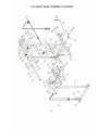
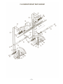
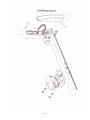
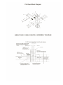
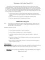
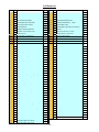
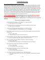
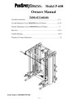
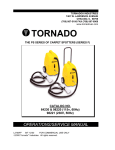
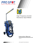
Model P-50
Owners Manual
Table of Contents
Assembly Instructions…………………………………..……..2-7
Use and Operation of Your PROSPOTfitness® Product…...…8-10
Periodic Maintenance of your PROSPOTfitness® Product….…11
Parts List…………………………………………………….…12
Trouble-Shooting ………………………………………….…13-14
Warranty & Contact Information……………………….…….15
Serial Number: 18604R00175P50
-- 1 --
Assembly Instructions for ProSpot Fitness® P-50
•
Before assembly, choose a safe location for your ProSpot Fitness® P-50. The ProSpot
Fitness® P-50 has a footprint of approximately 6’x 6’. The barbell is approximately 6'-6"
long. Locate your ProSpot Fitness® P-50 away from any source of water. Do not allow
any liquid to be near the machine or spilled on any electrical part. Do not insert any object
into the electrical box.
•
Approximate assembly time is 1/2 hour.
•
A flat area of 6’ x 8’ will be required to assemble and properly use the ProSpot Fitness®
P-50.
•
Enclosed you will find the following tools:
• 3 mm Allen Wrench
• 4 mm Allen Wrench
• 6 mm Allen Wrench
• 9/16" Allen Wrench
•
You will need the following tools and a helper to complete the assembly:
• 16 mm Hex Head Wrench
• 18 mm Hex Head Wrench
•
Floor Padding, such as cardboard, to avoid scratching your floor during assembly.
•
A good pair of scissors will be helpful in separating the parts from one another while
removing them from the cartons.
•
HAND TIGHTEN all bolts. DO NOT fully tighten bolts until instructed to do so.
•
Before assembly, separate and identify the right-sided parts from the left-sided parts.
These parts are easily distinguished by the manner in which the pre-drilled holes align with
corresponding parts, or are identified by “L “ & “R” stickers.
•
The ProSpot Fitness® P-50 uses different lengths of bolts. Be careful to use the correct
length of bolt called for at each step of assembly. Refer to the sizing charts provided.
• WARNING: Never perform any maintenance on the ProSpot Fitness®
P-50 while the Power Supply is plugged into the wall !!!
ALWAYS REMEMBER: After the initial set up of the system or after performing any
service on the unit, RESET the Computer on your ProSpot system before using it. Just unplug
the power supply from the Electronic Box, wait 30 seconds and plug back in. Resetting the
Computer allows it to recalibrate and work to its greatest efficiency.
-- 2 --
STEP # 1: P-50 MAIN FRAME ASSEMBLY
1. Place the two main pre-assembled side frames left & right respectfully opposite each other
in the center of the assembly area as shown in the Illustration. Place the Back Base Rail
(3) between the two Side Base Rails (1 & 2) so that the side pre-drilled holes of the Base
Rails (1 & 2) align with the end holes of the Back Base Rail (3).
2. Attach the two main pre-assembled side frames to the Back Base Rail (3) using two Cross
Brace Backing Plates (4), four bolts (66), eight washers (77) and four nuts (81) as shown.
HAND TIGHTEN the bolts at this time.
3. Now attach the two main pre-assembled side frames to the Top Rail (16) using four bolts
(66), eight washers (77) and four nuts (81) as shown. HAND TIGHTEN the bolts at this
time.
4. Attach Electronic Box Locating Board (11) to Back Base Rail (3) using two bolts (65), two
washers (77) and two nuts (81).
5. Tighten all bolts and nuts used for assembly in previous steps.
6. Carefully thread both Base Wire Harness's thru the center hole in the Back Base Rail (3).
7. Plug in both Base Wire Harness's into sides of Electronic Box (13).
8. Install Protective Cover (12) over Electronic Box with two screws (70).
9. Snap both Base Wire Harness's into Channels (90) and push any excess into hole in Side
Base Rails (1& 2).
10. Untie the coiled left & right Weight Bar Cables, so that they hang straight down with out
any twists or tangles. Be sure that the cables are straight and uncrossed and cables
and pulleys move smoothly.
STEP #2: SENSOR WEIGHT BAR INSTALLATION
1. Standing in front of the ProSpot Fitness® P-50. Insert one end and then the other end of
the Sensor Weight Bar (31) into the Cable Knuckles (46-48). Slide the Cable Knuckles
onto the Bar until they rest snugly against the preinstalled sensor retaining collars (45 &
48) at each end of the Sensor Weight Bar (31). (There is a rotation-limiting pin that
protrudes from the bottom of the Sensor Weight Bar (31) that must fit through a slot in the
knuckles (46-48) as it is slid into position).
2. Place one Plastic Locking Sleeve (36) onto each end of the Sensor Weight Bar (25) and
slide them inwards until they butt up against and secure the Weight Bar Cable Knuckle in
place. Tighten Plastic Locking Sleeve bolts securely with 4mm Allen wrench (95) provided.
3. Place one of the Olympic Adapters (32) onto the Sensor Weight Bar (31) and slide them
onto the Bar, then insert the Weight Bar Shoulder Bolt (34) onto each end of the Sensor
Weight Bar (31). Secure with provided 9/16" Allen wrench (97).
-- 3 --
-- 4 --
-- 5 --
-- 6 --
-- 7 --
!!Read!! This Page Before Using Your ProSpot Fitness® Product
Safe Use of Your ProSpot Fitness® Product
1.
CAUTION:
This machine involves the risk of possible injury by its user.
THE FOLLOWING RULES SHOULD BE CARFULLY FOLLOWED:
Consult a physician or other healthcare provider before beginning an exercise
program.
If you are in bad health or are handicapped, ask for the opinion of your
physician and exercise only under qualified supervision.
Discontinue to exercise if you experience any light-headedness, dizziness or
shortness of breath and consult your physician.
2.
Keep small children and others at a safe distance from all moving parts. The
up and down movement of the weights can be dangerous. Never allow your
fingers, toes, hair, other body parts or loose clothing to come near weights
while they are in motion. Never attempt to exercise with more weight than
you are physically able to handle. Periodically inspect your machine to ensure
all parts are free from defect and are fully operational. Check all fasteners to
make sure none have loosened with use. Tighten any loose fasteners if
necessary.
3.
Warning: Never perform any maintenance on the unit while the power
supply is plugged into the wall.
-- 8 --
User Instructions for the ProSpot Fitness® P-50
Do not allow any liquid to be near the machine or spilled on any electrical part. Do not insert any
foreign object into the electrical box or attempt to open it. If you have any questions or need help refer
to our web site at www.prospotfitness.com.
1.
Connect the power supply to a standard 110-volt household current. While connecting the
power supply do not touch the barbell as this may interfere with the computer’s initial settings.
If you need to reset the computer, simply unplug the power supply, wait 45 seconds and
reconnect it. It is recommended that surge protection be used to help protect and extend the life
of the Electronic Box of the unit from power surges and lightening strikes. A flashing green
light will appear on the Electronic Box when power is on.
Become familiar with the Grab and Go® operation BEFORE placing weights on the barbell.
2.
Position the Spot Blocks: Before positioning the Spot Blocks, place the barbell into the lowest
position for the exercise you will be performing. Move the barbell by grasping it and raising it
1” to unlock. While grasping the barbell raise or lower it into the desired position. Open hands
to lock the barbell in place. To move the Spot Blocks, place your index and middle fingers
underneath the finger grip and your thumb on the push-release lever. Push in the push-release
lever with your thumb and move the Spot Blocks so that they are touching the top of the sliderlocking block (the black block with the ProSpot Fitness® logo on it). Release the push-release
lever to lock the Spot Block in place.
3.
Assume a normal starting position for your desired free-weight exercise.
4.
Grasp the barbell:
I.
Rotate the barbell so that the Touch Sensor Strip embedded in the barbell is touching
your fingertips. It is necessary for your fingertips to maintain skin contact with the
Touch Sensor Strip throughout your free-weight exercise.
II. Learn the Rule Of Thumb: Sometimes referred to as a “false grip” or “sissy grip”,
ProSpot’s Rule Of Thumb is a style of grip in which the thumb does not wrap around
the bar but rests alongside the index fingers. Using this type of grip with your ProSpot
Fitness® equipment will prevent your thumb from maintaining skin contact with the
Touch Sensor Strip when you attempt to lock the bar in place.
III. Once you have grasped the barbell, you will hear a soft ‘click’ and a solid red light will
appear on the Electronic Box in addition to the flashing green power light.
5.
While still grasping the barbell, lift about 1”, using an even upward lifting motion on both sides
of the barbell. This upward movement will disengage the locking mechanism. If you have
performed this step correctly, the barbell will now be under your control, the cables will move
freely over the pulleys and the slider knuckles will slide smoothly up and down the guideposts.
You can now safely perform any free-weight exercise without the need of a spotter. Simply
Grab and Go®!
-- 9 --
6.
Locking the barbell in place: When you are finished with using the barbell, open your hands to
remove your fingertips from the Touch Sensor Strip at the same continue to support the barbell
with your palms. (Make sure no other skin contact is being made with the Touch Sensor Strip.)
Slowly lower the barbell until it locks into position. There is a locking position every 1”. Now
remove your palms from the barbell. The barbell is now locked and ready for your next
exercise.
7.
Always maintain control of the movement of the barbell. Do not allow the barbell to swing
against the machine frame, as this may cause damage to the finish. Do not attempt to throw or
slam the barbell attached to the cables, as this may result in damage to the locking mechanism.
Intentional misuse of the P-50 will void any and all warranties.
Once familiar with the Grab and Go® operation, you can now begin using the barbell with weight
plates.
8.
Position Spot Blocks for the desired exercise. (Refer to #2 above.)
9.
Make certain the barbell is level before loading weight plates. Level the barbell by raising up
one end of the barbell until it is level. (The P-50 is equipped with a ratcheting feature that
allows the barbell to be manually raised from side-to-side.) Or, level the barbell by grasping it
with both hands, making sure the fingertips make contact with the touch sensor strip. Lift the
barbell upward about 1” to release it from the locking mechanism and place it in a level
position. Once the barbell is level, open your hands to lock it in place. Load weights evenly
on both sides of the barbell.
10. Secure all weight plates with a spring clip or locking collar. You are now ready to begin your
free-weight exercise routine.
11. Perform your exercise following the steps outlined in #2-6 above.
12. Before removing the weight plates from the barbell, make sure it is in a level position.
13. Never attempt to lift more weights than you can safely handle. Never put more than 350
pounds on the barbell.
-- 10 --
Maintenance of the ProSpot Fitness® P-50
Our products are made of durable materials and have been factory tested to assure proper
function and reliability. Along with our Equipment Warranty, this gives the owner of our product
the confidence of a long lasting relationship with ProSpot Fitness® Inc. Our systems are designed
in a way to allow easy replacement of parts both mechanical and electrical if the need should ever
arise. If you are a new owner of a ProSpot Fitness® system, three important things need to be done
to assure prompt service under the warranty:
1. Fill out and fax or mail to us your Product Warranty Registration Card along with a
copy of your sales receipt (proof of purchase) if your dealer has not done this at time of
purchase.
2. Your system needs to be set up properly according to the assembly manual.
3. Follow user instructions on how to properly use the system.
Maintenance Program
Note:
Our products are recommended for climate-controlled environments. Outdoor use is not
recommended and will void the warranty. Carefully inspect machine before each use to
determine that it is free from defects.
Do NOT use machine if you find:
1. A loose, broken or frayed cable – (needs to be replaced)
2. A loose, broken or frayed power cord – (needs to be replaced)
3. Any broken, cracked, torn, frayed or defective part of the machine – (needs to be
replaced)
4. Loose bolts or fasteners. Check all fasteners to make sure none have loosened with use.
Tighten any loose fasteners.
5. Pulleys sticking or Cables binding. Check for free movement of all cable and pulleys.
Adjust or replace if necessary.
Lubrication:
Lubricate the Internal locking Blocks periodically by spraying a standard silicone lubricant into the top
of the # 8 & 9 Locking Upright Posts in the inside corners of the tube. Do not over lubricate.
Warning: Never perform any maintenance on the unit while the power supply is
plugged into the wall.
-- 11 --
P-50 Parts List
New Old
quan
New Old
quan
1
27 Right Side Base Rail
1
51
37 Slider Cable Knuckle Outer Section
2
2
28 Left Side Base Rail
1
52
52 Slider Cable Knuckle Center Section
1
3
2
1
53
38 Slider Cable Knuckle Outer Section
2
4
13 Rear Upright Support Plate
2
54
53 Slider Knuckle Retaining Pin
2
5
55 Front Upright Post support Plate
4
55
75 Retaining Pin Snap Ring
4
6
21 Logo Foot End Cap 63.5mm
4
56
8
7
10 Front Upright Post
2
57
20 Locking Slider Tube Guide 59.5 x 53mm
4
8
11 Left Rear Locking Upright Post
1
58
94 Solenoid
2
Back Base Rail
12mm
Locking Slider Frame
2
9
12 Right Rear Locking Upright Post
1
59
72 Solenoid Pin Roll Pin 3 x 12mm
2
10
14 Inspection Cover
2
60
19 Solenoid Roll Pin Locking Clip
2
11
25 Electronic Box Locating Board
1
61
9
Solenoid Locking Spring
2
12
3
1
62
54
Locking Pall Arm Shaft
2
13
30 Electronic Box
1
63
73 Locking Arm Shaft Retaining Snap Ring 8mm
4
14
31 Power Suppy
1
64
7
2
15
29 Deflection Plate
2
65
59 Hex Head Screw M12 x 85mm
6
16
1
Top Rail
1
66
60 Hex Head Screw M12 x 90mm
20
17
49
Logo
1
67
61 Hex Head Screw M10 x 85mm
4
18
24 Upper Linking Plate
4
68
62 Hex Head Screw M6 x 75mm
4
19
18
Plastic Insert Cap 63.5mm
2
69
63 Button Head Socket Cap Screw M8 x 15mm
6
20
56
Big Pulley, double-groove
4
70
64 Flat Phillips machine screw M4 x 5mm
2
21
26 Cable Keeper Tube
4
71
65 Chamfer Bolt M5 x 20mm
8
22
23 Upper Linking Plate Steel Spacer Tube
2
72
66 Chamfer Bolt M5 x 25mm
8
23
4
Spot Block Frame 75mm
2
73
67 Chamfer Bolt M4 x 10mm
16
24
5
Spot Block Locking Pin Bracket
2
74
68 Flat Phillips machine screw M4 x 8mm
16
25
6
Spot Block Arm Shaft
2
75
69 Flat Washer 4mm
4
26
15 Spot Block Plastic Insert Guide 75 X 63.5 mm
4
76
70 Flat Phillips machine screw M4 x 10mm
1
27
17 Spot Block Nylon Side Bracket
4
77
78 Flat Washer 12mm
52
28
22 Spot Block Rectangle Locking Spring
4
78
79 Flat Washer
8
29
74 Spot Block Shaft Retaining Snap Ring 10mm
4
79
80 Split Lock Washer 4mm
16
30
57 Spot Block Position Decal
2
80
83 Nylon Insert Lock Nut M10
4
31
32 Sensor Weight Bar
1
81
84 Nylon Insert Lock Nut M12
26
32
42 Weight Bar Olympic Adapter
2
82
85 Nylon Insert Lock Nut M6
4
33
43 Weight Bar Olympic Adapter PVC Tube
2
83
86 Flat Washer
8
34
82 Weight Bar Shoulder Bolt 1/2"-13
2
84
87 Flat Washer
1
35
50 Weight Bar Bronze Bushing
2
85
88 Flat Phillips machine screw M6 x 20mm
4
36
41 Weight Bar Plastic Locking Sleeve
2
86
89 Flat Phillips machine screw M6 x 10mm
8
37
98 Weight Bar Foam Pad
1
87
90 Nut M5
16
38
44 Weight Bar Center Rubber Stop
1
88
92 Flat Phillips machine screw ST 2.9 x 9.5
4
39
46 Weight Bar Rubber Sensor Rod Channel
2
89
93 Flat Phillips machine screw ST 2.9 x 13
6
40
47 Weight Bar Sensor Rod
2
90
16 Base Rail Wire Channel
2
41
33 Weight Bar Sensor Retaining Collar Top Half
2
91
48 Base Rail Wire Rubber Grommet
4
42
34 Weight Bar Sensor Retaining Collar Btm. Half
2
92
95 Base Frame Wire Harness
2
43
39 Sensor Collar Brass Contact Pin
2
93
96 Spiral Cable
2
44
45 Sensor Collar Brass Contact Pin Spring
2
94
76 Hex Key Wrench Size 3mm
1
45
71 Sensor Collar Set screw
2
95
77 Hex Key Wrench Size 4mm
1
46
35 Cable Knuckle Outer Section w/ Contact Plate
2
96
40 Hex Key Wrench Size 6mm
1
47
36 Cable Knuckle Center Section
2
97
81 Hex Key Wrench Size 9/16"
1
48
51 Cable Knuckle Outer Center
2
98
49
58
Weight Bar Cable Inner (Short)
2
50
91
Weight Bar Cable Outer (Long)
2
Protective Cover
-- 12 --
Locking Pall Arm
Number Decal
2
Trouble-Shooting Guide
How the Patented ProSpot Fitness® System Works:
Starting from the Computer Brain, a signal is sent from the left & right side, thru the L & R Grey Base
Frame Wire Harness (white lead), to the Spiral Cord Harness (brown lead), to the Slider Block Cable
Knuckle connector, to inside Barbell Cable to the Sensor on the Barbell. When skin contacts is made
with Barbell Sensors, the signals return to the Computer Brain, at which a 12-volt charge is sent via the
wire harness's (red & black leads), to the solenoids, to release the spring loaded Slider Block Locking
Pins when the Barbell is lifted, allowing the Barbell to move up and down. When skin contact with
Barbell Sensor is broken by either hand, the Computer Brain reads this and stops the 12-volt charge to
the solenoids, at which time, the spring loaded Locking Pins instantaneously engages the hole on the
Guide Post and locks the Barbell from any downward movement.
ALWAYS REMEMBER: After performing any service on the unit, RESET the Computer
on your ProSpot system before using it. Just unplug the power supply Electronic Box, wait 30
seconds and plug back in. Resetting the Computer allows it to recalibrate and work to its greatest
efficiency.
Electrical Service Inspection Checklist:
1. Check for proper functioning of wall receptacle. (Test plug for power)
a. If bad, find new AC power supply.
2. Check wall transformer connection to Electronic Box. Should not be bent or loose.
a. If bad, replace Electronic Box.
3. Check for green flashing light, the indication power to Electronic Box.
a. If no green light, test 12V Wall Adapter for 12-17 volts output.
4. Inspect white connectors from Gray Base Frame Wire Harness connection on Electronic Box
for loose wires.
a. If loose, plug in tight.
b. If broken, replace Gray Base Frame Wire Harness.
5. Inspect Gray Base Frame Wire Harness for possible pinching in frame during assembly.
a. Replace Gray Base Frame Wire Harness if damaged or defective.
6. Inspect Gray Base Frame Wire Harness connection to Spiral Cord Harness.
a. If loose, plug in tight.
b. If broken, replace Gray Base Frame Wire Harness or Spiral Cord Harness.
7. Inspect Spiral Cord connection to Solenoids, Red and Black.
a. If loose, plug in tight.
b. If broken, replace Spiral Cord Harness.
8. Inspect Spiral Cord Brown Lead Sensor Cable Knuckle plug.
a. If loose, plug in tight.
b. If broken, replace Spiral Cord Harness.
9. Check contact of Sensor Collar Brass Pin with Cable Knuckle plate.
a. If no contact, adjust Sensor Collar closer. (See Weight Bar / Cable-Knuckle Assembly
Diagram)
-- 13 --
Trouble-Shooting Guide (con't)
Symptom:
Solution:
Sensor Weight Bar will not unlock.
1. Remove #10 Inspection covers on both sides to gain access to #93 Spiral cord wire
Harness.
2. Unplug Brown Sensor plugs and hold one in each hand at the same time.
3. If sensor triggers (red light on box) then, Wire Harness is good.
a. Now perform adjustments shown on Weight Bar / Cable-Knuckle Assembly
Diagram.
4. If sensor fails to trigger (no red light) then:
a. Re-check Wire Harness with Meter (Continuity test) for defect wire and
replace.
Symptom:
Solution:
Sensor Weight Bar locks prematurely during work out.
1. Perform Adjustments shown on Weight Bar / Cable-Knuckle
Assembly Diagram.
2. Check Wire Harness for defective wire. (Continuity test)
Symptom:
Solution:
One side of system will not unlock.
1. Check Double Cable Pulleys for free movement.
2. Check Solenoid connections. (Red and Black wires)
3. Check free movement of Locking Pin. (Manually pull down Pin)
4. Trigger Sensor and test for 10-12 volts at Solenoid connection.
a. If 10-12 volts the replace Solenoid.
b. If no voltage, then check Wire Harness for defective wire. (Continuity test)
c. If Wire Harness is good the replace Electronic Box.
Symptom:
Solution:
Sensor Rod on Weight bar keeps popping up.
1. Remove Sensor Collar and Sensor Rod.
2. Straighten any bends. (If too bent up, replace.)
3. Before reinstalling, bend angle in Sensor Rod slightly downward, so that there is
tension to Rod to seat it.
4. Adjust Sensor Collar. (See Weight Bar / Cable-Knuckle Assembly Diagram, Step
#1)
-- 14 --
Warranty & Contact Information
Each ProSpot Fitness® Product comes with a limited parts replacement warranty. Please refer to the
actual warranty card included with your system for specific coverage.
Remember: To activate your Warranty, fill out and fax or mail to us your Product Warranty
Registration Card along with a copy of your sales receipt (proof of purchase) if your dealer has not
done this at time of purchase.
For more information please refer to our Website at: www.prospotfitness.com.
If you have additional questions about the warranty, please write or call us:
ProSpot Fitness® Inc.
Attn: Warranty Service
1325 Oakbrook Drive, Suite E
Norcross, GA 30093
Office (770) 446-9299
Fax (770)-446-7213
Contacting ProSpot Fitness Technical Support:
Our Service Department can be reached Monday through Friday, 9am-5 pm EST.
Or, e-mail us: [email protected]
If ordering replacement parts, please refer to the Owners Manual for part numbers and description.
Note: Owners Manuals & Warranty Registration cards can be down loaded from our web site.
-- 15 --