1
Owner's Manual
CRAFTSMAN
i
P
R
0
S
I o HAL
i
ROTARY LAWN MOWER
160cc Honda Engine
Power-Propelled
22" Multi-Cut
Model No.
944.361361
CAUTION'.
Read and follow all
Safety Rules and Instructions
before operating this equipment
Sears Canada, Inc., Toronto, Ontario M5B 2B8
Safety Rules .........................................
2-3
Warranty ...............................................
4-5
Product Specifications
........................... 5
Assembly/Pre-Operation
......................... 6
Operation ............................................
7-11
Maintenance Schedule .......................... 12
Maintenance .....................................
Service and Adjustments ..................
Storage .............................................
Troubleshooting ................................
Repair Parts ......................................
Sears Service .......................... Back
IMPORTANT:
This cutting machine is
capable of amputating hands and feet and
throwing objects. Failure to observe the
following safety instructions could result in
serious injury or death.
• Do not pull mower backwards
unless
absolutely necessary. Always look down
and behind before and while moving
backwards.
• Never direct discharged material toward
anyone.
Avoid discharging
material
against a wall or obstruction.
Material
may richochet back toward the operator. Stop the blade when crossing gravel
surfaces.
• Do not operate the mower without proper
guards, plates, grass catcher or other
safety protective devices in place.
• See manufacturer's instructions for proper
operation and installation of accessories.
Only use accessories approved by the
manufacturer.
• Stop the blade(s) when crossing gravel
drives, walks, or roads.
• Stop the engine (motor) whenever you
leave the equipment, before cleaning the
mower or unclogging the chute.
• Shut the engine (motor) off and wait until
the blade comes to complete stop before
removing grass catcher.
• Mow only in daylight or good artificial
light.
• Do not operate the machine while under
the influence of alcohol or drugs.
• Never operate machine in wet grass. Always be sure of your footing: keep a firm
hold on the handle; walk, never run.
• Disengage the self-propelled mechanism
or drive clutch on mowers so equipped
before starting the engine.
• If the equipment should start to vibrate
abnormally, stop the engine (motor) and
check immediately for the cause. Vibration
is generally a warning of trouble.
• Always wear safety goggles or safety
glasses with side shields when operating
mower.
ALook for this symbol to point out important safety precautions. It means
CAUTION!!!
BECOME ALERT!!!
YOUR SAFETY IS INVOLVED.
A WARNING:
In order to prevent accidental starting when setting up, transporting, adjusting or making repairs,
always disconnect spark plug wire and
place wire where it cannot come in contact
with plug.
A CAUTION:
Muffler and other engine
parts become extremely hot during
operation and remain hot after engine
has stopped. To avoid severe burns on
contact, stay away from these areas.
I. GENERAL
OPERATION
• Read, understand, and follow all instructions on the machine and in the manua!(s)
before starting. Be thoroughly familiarwith
the controls and the proper use of the machine before starting.
• Do not put hands or feet near or under
rotating parts. Keep clear of the discharge
opening at all times.
• Only allow responsible individuals, who
are familiar with the instructions, to operate the machine.
• Clear the area of objects such as rocks,
toys, wire, bones, sticks, etc., which could
be picked up and thrown by blade.
• Be sure the area is clear of other people
before mowing. Stop machine if anyone
enters the area.
• Do not operate the mower when barefoot
or wearing open sandals. Always wear
substantial foot wear.
Ii. SLOPE
12-15
16-17
17-18
18-19
20-29
Cover
OPERATION
Slopes are a major factor related to slip & fall
accidents which can result in severe injury.
All slopes require extra caution. If you feel
2 uneasy on a slope, do not mow it.
DO:
• Never fill containers inside a vehicle, on
a truck or trailer bed with a plastic liner.
Always place containers on the ground
away from your vehicle before filling.
• Remove gas-powered equipmentfrom the
truck or trailer and refuel iton the ground. If
this is not possible, then refuel such equipmentwith a portable container, rather than
from a gasoline dispenser nozzle.
• Keep the nozzle in contact with the rim
of the fue! tank or container opening at
all times until fueling is complete. Do not
use a nozzle lock-open device.
• Iffue! is spilled on clothing, change clothing
immediately.
• Never overfill fue! tank. Replace gas cap
and tighten securely.
• Mow across the face of slopes: never up
and down. Exercise extreme caution when
changing direction on slopes.
• Remove obstacles such as rocks, tree
limbs, etc.
• Watch for holes, ruts, or bumps. Tall grass
can hide obstacles.
DO NOT:
• Do not trim near drop-offs, ditches or
embankments.
The operator could lose
footing or balance.
• Do not trim excessively steep slopes.
• Do not mow on wet grass. Reduced footing
could cause slipping.
Iii. CHILDREN
Tragic accidents can occur if the operator is
not alert to the presence of children. Children
are often attracted to the machine and the
mowing activity. Neverassume that children
will remain where you last saw them.
• Keep children out of the trimming area
and under the watchful care of another
responsible adult.
• Be alert and turn machine off if children
enter the area.
• Before and whilewalking backwards, look
behind and down for small children.
• Never allow children to operate machine.
• Use extra care when approaching blind
corners, shrubs, trees, or other objects
that may obscure vision.
IV. SAFE HANDLING
V. GENERAL
SERVICE
• Never run machine inside a closed area.
• Never make adjustments or repairs with
the engine (motor) running. Disconnect
the spark plug wire, and keep the wire
away from the plug to prevent accidental
starting.
• Keep nuts and bolts, especially blade attachment bolts, tight and keep equipment
in good condition.
• Never tamper with safety devices. Check
their proper operation regularly.
• Keep machine free of grass, leaves, or
other debris build-up. Clean oil or fue! spillage. Allow machine to cool before storing.
• Stop and inspect the equipment if you
strike an object. Repair, if necessary,
before restarting.
• Never attempt to make wheel height adjustments while the engine is running.
• Grass catcher components are subject to
wear, damage, and deterioration, which
could expose moving parts or allowobjects
to be thrown. Frequently check components and replace with manufacturer's
recommended parts, when necessary.
• Mower blades are sharp and can cut. Wrap
the blade(s) orwear gloves, and use extra
caution when servicing them.
• Do not change the engine governorsetting
or overspeed the engine.
• Maintain or replace safety and instruction
labels, as necessary.
OF GASOLINE
Use extreme care in handling gasoline.
Gasoline is extremely flammable and the
vapors are explosive.
• Extinguish all cigarettes, cigars, pipes and
other sources of ignition.
• Use only an approved container.
• Never remove gas cap or add fuel with
the engine running. Allow engine to cool
before refueling.
• Never refuel the machine indoors.
• Never store the machine or fuel container
where there is an open flame, spark or pilot
light such as a water heater or on other
appliances.
&WARNING:
This lawn mower is equipped with an internal combustion engine and
should not be used on or near any unimproved forest-covered, brush-covered or
grass-covered land unless the engine's exhaust system is equipped with a spark
arrester meeting applicable local or state laws (if any). If a spark arrester is used, it
should be maintained in effective working order by the operator.
A spark arrester for the muffler is available through your nearest Sears Service Centre (See the REPAIR PARTS section of this manual).
3
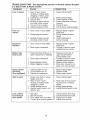
GENERAL:
Craftsman products are warranted to be free from defects in materials
or workmanship
for a specific time period as set-out below (the "Warranty Period").
Warranties extend to the original purchaser of a Craftsman product only. Purchases
made through an online auction or through any website other than www.sears.ca
are
excluded.
The relevant Warranty Period commences on the original date of purchase.
Within this period, Sears Canada, Inc. will, at its sole option, repair or replace any products
or components which fail in normal use. Such repairs or replacement will be made at no
charge to the customer for parts or labor, provided that the customer shall be responsible
for any transportation cost.
EXCLUSIONS: This warranty does not cover failures due to normal wear, abuse, misuse,
neglect (including but not limited to the use of stale fuel, dirt, abrasives, moisture, rust,
corrosion, or any adverse reaction due to improper storage or use habits), improper
maintenance or failure to follow maintenance guidelines and/or instructions, failure to
operate the product in accordance with the owner's manual or any additional instructions
or information provided at the time of purchase or in subsequent communications with
the original purchaser, accident or unauthorized alterations or repairs made or attempted
by others. Also excluded from warranty coverage - except as provided below - are the
following: maintenance,
adjustments,
components
subject to wear including but not
limited to: cosmetic components, belts, blades, blade adapters, bulbs, tires, filters, guide
bars, lubricants, seats, grips, recoil assy's, saw chains and bars, trimmer lines and spools,
spark plugs, starter ropers and tines, and discoloration resulting from ultraviolet light. Any
product missing the model and/or serial number identification label will be disqualified
from coverage under this warranty.
REPAIRS: Repairs have a 90 day warranty. If the defective product is still within the
Warranty Period, then the new warranty is 90 days from the date of repair or to the end of
the original Warranty Period, whichever period is longer.
DISCLAIMERS:
THE WARRANTIES
AND REMEDIES CONTAINED
HEREIN ARE
EXCLUSIVE AND IN LIEU OF ALL OTHER WARRANTIES,
WHETHER ORAL OR
WRITTEN (OTHER THAN AS STATED HEREIN), AND WHETHER EXPRESS, IMPLIED
OR STATUTORY,
INCLUDING
BUT NOT LIMITED TO ANY. THIS WARRANTY
GIVES YOU SPECIFIC LEGAL RIGHTS, WHICH MAY VARY FROM PROVINCE TO
PROVINCE.
IN NO EVENT SHALL SEARS BE LIABLE FORANY
INCIDENTAL,
SPECIAL,
INDIRECT
OR CONSEQUENTIAL
DAMAGES,
WHETHER
RESULTING
FROM THE USE, MISUSE
OR INABILITY
TO USE THE PRODUCT
OR FROM DEFECTS
IN THE PRODUCT.
THE
EXCLUSIONS
IN THIS PARAGRAPH
SHALL NOT APPLY IN JURISDICATIONS
WHERE
APPLICABLE
LAW DOES NOT ALLOW
FOR THE EXCLUSION
OF INCIDENTAL
OR
CONSEQUENTIAL
DAMAGES.
IN SUCH JURISDICTIONS,
NOT APPLY,
BUT THE REMAINING
PROVISIONS
OF
REMAIN VALID.
THIS
THIS
PARAGRAPH
DOCUMENT
SHALL
SHALL
Sears retains the exclusive right to repair or replace the product or offer a full refund of
the purchase price at its sole discretion. SUCH REMEDY SHALL BE YOUR SOLE AND
EXCLUSIVE REMEDY FOR ANY BREACH OF WARRANTY.
CUSTOMER
RESPONSIBILITIES:
In additional
to complying
with all suggested
maintenance guidelines and instructions, customers' obligations shall include but shall
not be limited to: operating the product in accordance with the owner's manual or any
additional instructions or information provided at the time of purchase or in subsequent
communications
to the purchaser from time to time, exhibit reasonable care in the use,
operation, maintenance, general upkeep and storage of the product. Failure to comply
with these requirements will void any applicable warranty.
4
LIST OF APPLICABLE WARRANTY PERIODS: The following list contains the applicable
Warranty Period for your Craftsman product and is based on a combination of the type of
product or component and the intended and actual use of the product or component:
.
.
.
.
.
90 DAYS: Craftsman products intended for use or actually
institutional, professional or income-producing
purposes
used for commercial,
2 YEARS: Craftsman riding lawn mowers, yard and garden tractors, walk behind
mowers, tillers, brush cutters, snow blowers, handheld blowers, backpack blowers,
hedge trimmers and electrical products for noncommercial,
nonprofessional,
noninstitutional, or non-income-producing
use, except for those components which are
part of engine systems manufactured by third party engine manufacturers for which
the purchase has received an separate warranty with product information supplied at
the time of purchase.
1 YEAR: Craftsman power cutters, stump grinders, pole pruners, gas chain saws,
electric chain saws, trimmer attachments, baggers and pole saws for noncommercial,
nonprofessional,
non-institutional, or non-income-producing
use.
90 DAYS: All defective batteries, which will be replaced during this 90-day Warranty
Period.
60 DAYS: Additional Warranty Period of 60 days will apply to adjustments and worn
products or components BUT DOES NOT INCLUDE WEAR OR ADJUSTMENTS
for products used for commercial, institutional, professional or income-producing
purposes. Wear items include but are not limited to: belts, blades, tires, spark plugs,
air filters, chains, shear bolts, skid plates, scraper bars, drift cutters, ropes, tines,
collection bags and pulleys.
As the Warranty Period runs from the date of purchase and NOT from the date that a
product is delivered, opened, assembled or first used, plea se ensure during this time
period that your product or component has been assembled and tested for correction
operation regardless of when you intend to actually use it. Claims made after the
Warranty Period has expired will not be honored.
PROOF OF PURCHASE/DOCUMENTATION:
Warranty coverage is conditioned upon
the original purchaser furnishing Sears Canada or its authorized third party service
provider if applicable, with the original sales receipt or other adequate written proof of
the original purchase date and identification of the product. In the event that the original
purchaser is unable to provide a company of the original sales receipt, Sears Canada
Inc. reserves the right to determine in its sole discretion what other written proof of the
original purchase date and identification of the product is acceptable.
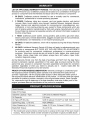
Serial Number:
Date of Purchase:
Gasoline Capacity / Type:
0,94 Litres (Unleaded
Oil Capacity:
0,5 Litres
Oil Type (API SG-SL):
SAE 30 (above 0°C/32°F)
Spark Plug (Gap: 0,76 mm)
NGK BPR6ES
Valve Clearance
Intake: 0.015 mm; Exhaust: 0.020 mm
(+ 0.04 mm):
Blade Bolt Torque:
Regular)
or SAE 10W-30
35-40 ft. Ibs.
• The model and serial numbers wil! be found on a decal on the rear of the lawn mower
housing. Record both serial number and date of purchase in space provided above.
5
Read these instructions and this manual in its entirety before you attemptto assemble
or operate your new lawn mower.
IMPORTANT:This lawn mower is shipped WITHOUTOIL OR GASOLINEin the engine.
Your new lawn mower has been assembledatthe factorywith the exception ofthose parts
left unassembledfor shipping purposes. Toensure safe and proper operationofyour lawn
mower,all parts and hardwareyou assemble must be tightened securely. Use the correct
tools as necessaryto ensure propertightness. All parts such as nuts,washers,bolts, etc.,
necessaryto complete the assembly have been placed in the parts bag.
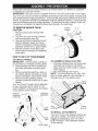
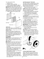
TO REMOVE
CARTON
MOWER FROM
Handle
bracket
1. Remove loose parts included with
mower.
2. Cut down two end corners of carton
and lay end panel down flat.
3. Remove all packing materials except
padding between upper and lower
handle and padding holding operator
presence control bar to upper handle.
4. Roll lawn mower out of carton and
check carton thoroughly for additional
loose parts.
Bolt
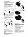
NOW TO SET UP YOUR MOWER
TO UNFOLD
HANDLE
TO ASSEMBLE
iMPORTANT:
Unfold handle carefully so
as not to pinch or damage control cables.
1. Raise handles until lower handle section locks into place in mowing position.
2. Remove protective padding, raise upper handle section into place on lower
handle and tighten both handle knobs.
3. Remove handle padding holding
operator presence control bar to upper
handle.
Your lawn mower handle can be adjusted
for your mowing comfort. Refer to "ADJUST HANDLE" in the Service and Adjustments section of this manual.
Operator
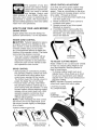
GRASS CATCHER
1. Put grass catcher frame into grass bag
with rigid part of bag on the bottom.
Make sure the frame handle is outside
of the bag top.
2. Slip vinyl bindings over frame.
NOTE: If vinyl bindings are too stiff, hold
them in warm water for a few minutes. If
bag gets wet, let it dry before using.
MOWING
POSITION
b_,
control bar
///
////
/
/
j ////X
/
,/
LIFT
UP
Vinyl
bindings
Upper
handle
Frame
opening
TO iNSTALL ATTACHMENTS
Your lawn mower was shipped ready to be
used as a mulcher. To convert mower to
bagging or discharging, see "TO CONVERT MOWER" in the Operation section
of this manual.
Handle
knob
Lower handle
6
KNOW YOUR LAWN
MOWER
READ THIS OWNER'S MANUAL AND ALL SAFETY RULES BEFORE OPERATING
YOUR LAWN MOWER. Compare the illustrations with your lawn mower to familiarize
yourself with the location of various controls and adjustments.
Save this manual for
future reference.
These symbols may appear on your lawn mower
product. Learn and understand their meaning.
CAUTION
OR WARNING
ENGINE
ON
ENGINE
OFF
FAST
SLOW
CHOKE
or in literature supplied
FUEL
OIL
with the
DANGER, KEEP HANDS
AND FEET AWAY
Operator presence control bar
Drive control levers
Handle knobs
Starter
handle
Gasoline filler cap
Fuel valve lever
Grass
catcher
Air filter
Spark
plug
Engine oil cap
with dipstick
Muffler
J
Housing
Mulcher door
Wheel adjuster
(on each wheel)
IMPORTANT: This lawn mower is shipped
WITHOUT OIL OR GASOLINE in the engine.
MEETS CPSC SAFETY REQUIREMENTS
Sears rotary walk-behind power lawn mowers conform to the safety standards of the
American National Standards Institute and the U.S. Consumer Product Safety Commission. _I,WARNING: The blade turns when the engine is running.
Operator presence control bar- must
be held down to the handle to start the
engine. Release to stop the engine.
Starter handle - used for starting engine,
Drive control levers - used to engage
power-propelled forward motion of mower.
Mulcher door - allows conversion to
discharging or bagging operation.
7
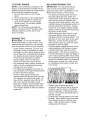
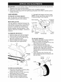
DRIVE CONTROL
The operation of any lawn
SAFETVG'ASSES
mower can result in foreign
objects thrown into the eyes,
which can result in severe
eye damage. Always wear
safety glasses or eye shields while operating your lawn mower or performing any
adjustments or repairs. We recommend a
standard safety glasses orwide vision safety
mask worn over spectacles.
ADJUSTMENT
Over time, the drive control system may
become "loose", resulting in decreased
speed. There is a turnbuckle on the drive
control housing to increase tension on the
drive cable. Proceed as follows:
1. Turn unit off and disconnect spark plug
wire from spark plug.
2. Rotate turnbuckle on drive control to
increase drive speed.
3. Operate mower to test drive speed.
Readjust as required.
4. If condition fails to improve after the
above steps (forward speed remains
the same), your drive belt is worn and
should be replaced.
HOW TO USE YOUR LAWN MOWER
ENGINE SPEED
Engine speed was set at the factory for
optimum performance. It is not adjustable.
ENGINE ZONE CONTROL
_CAUTION:
Federal regulations require
an engine control to be installed on this
lawn mower in order to minimize the risk
of blade contact injury. Do not under
any circumstances attempt to defeat the
function of the operator control. The blade
turns when the engine is running.
• Your lawn mower is equipped with an
operator presence control bar which
requires the operator to be positioned
behind the lawn mower handle to start
and operate the lawn mower.
Adjustment
turnbuckle
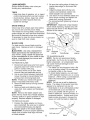
TO ADJUST CUTTING HEIGHT
Raise wheels for low cut and lower wheels
for high cut, adjust cutting height to suit
your requirements. Medium position is
best for most lawns.
• To change cutting height, pull up on
adjuster lever, move wheel up or down
to suit your requirements and release
adjuster lever. Be sure all wheels are in
the same setting.
NOTE: Adjuster is properly positioned
when lever inserts into hole in plate.
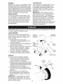
DRIVE CONTROL
• Self-propelling is controlled by holding
the operator presence control bar down
to the handle and pulling either drive
control lever rearward to the handle.
The further toward the handle a lever is
pulled, the faster the unit will travel.
. Forward motion will stop when either
the operator presence control bar or a
drive control lever are released. To stop
forward motion without stopping engine,
release a drive control lever only. Hold
operator presence control bar down
against handle to continue mowing
without self-propelling.
NOTE: If after releasing the drive control
the mower will not roll backwards, push
the mower forward slightly to disengage
drive wheels.
LEVER BACKWARD
TO LOWER MOWER
Lever
LEVER
FORWARD
TO RAISE MOWER
Plate
Operator presence control bar
rive
control levers
TO ENGAGE
DRIVE CONTROL
DRIVE CONTROL
DISENGAGED
-....
8
TO CONVERT
MOWER
I
Your lawn mower was shipped ready to be
used as a mulcher. To convert to bagging
or discharging:
REAR BAGGING
• Lift rear door of the lawn mower and
place the grass catcher frame hooks
onto the grass bag brackets.
• To convert to mulching or discharging
operation, remove grass catcher and
close rear door.
\
\
Unlock
latch
Open
mulcher door
I
I
door
Grass bag
bracket
\
Grass
"\
catcher
\.,
handle
Discharge
deflector
Grass
frame hook
\
NOTE: Rear door will remain open until
operator presence control bar is held
down to the handle.
,ACAUTION:
Do NOT force rear door to
close. Serious damage to your mower
could result.
SIMPLE STEPS TO
REMEMBER WHEN
CONVERTING YOUR LAWN MOWER
FOR MULCHING 1. Rear door closed.
2. Mulcher door closed and locked.
FOR REAR BAGGING 1. Grass catcher installed.
2. Mulcher door closed and locked.
FOR SIDE DISCHARGING 1. Rear door closed.
2. Discharge deflector installed.
_,CAUTION:
Do not run your lawn mower without rear door closed or approved
grass catcher in place. Never attempt to
operate the lawn mower with the rear door
removed or propped open.
SIDE DISCHARGING
• Rear door must be closed.
• Open mulcher door and install discharge deflector under door as shown.
• Mower is now ready for discharging
operation.
• To convert to mulching or bagging
operation, discharge deflector must be
removed and mulcher door must be
closed and locked.
9
TO EMPTY GRASS CATCHER
1. Lift up on grass catcher using the
frame handle.
2. Remove grass catcher with clippings
from under lawn mower handle.
3. Empty clippings from bag using both
frame handle and bag handle.
NOTE: Do not drag the bag when emptying; it will cause unnecessary wear.
Grass
catcher
frame
\
/
Bag
handle
_:_:__:,
BEFORE
STARTING
ENGINE
ADD OIL
Your lawnmower is shipped without oil in
the engine. For type and grade of oil to
use, see "ENGINE" in the Maintenance
section of this manual.
,A CAUTION: DO NOT overfill engine with
oil, or it will smoke on startup.
1. Be sure lawnmower is level.
2. Remove oil fill cap/dipstick from oil fill
spout.
3. You recieve a container of oil with the
unit. Slowly pour the entire container
down the oil fill spout into the engine.
4. Insert and tighten oil fill cap/dipstick.
IMPORTANT:
• Check oil level before each use. Add oil
if needed. Fill to full line on dipstick.
• Change the oi! after every 25 hours of
operation or each season. You may
need to change the oil more often
under dusty, dirty conditions. See "TO
CHANGE ENGINE OIL" in the Maintenance section of this manual.
Oil fill cap /
di
ADD GASOLINE
• Fill fuel tank to bottom of tank filler neck.
Do not overfill. Use fresh, clean, regular
unleaded gasoline with a minimum of
87 octane. Do not mix oil with gasoline.
Purchase fuel in quantities that can be
used within 30 days to assure fuel freshness.
• i, CAUTION: Wipe off any spilled oil or
fuel. Do not store, spill or use gasoline
near an open flame.
,A CAUTION: Alcohol blended fuels
(called gasohol or using ethanol or methanol) can attract moisture which leads to
separation and formation of acids during
storage. Acidic gas can damage the fuel
system of an engine while in storage. To
avoid engine problems, the fuel system
should be emptied before storage of 30
days or longer. Empty the gas tank, start
the engine and let it run until the fuel lines
and carburetor are empty. Use fresh fuel
next season. See Storage Instructions for
additional information.
Never use engine
or carburetor cleaner products in the fuel
tank or permanent damage may occur.
TO STOP
ENGINE
. To stop engine, release operator presence control bar. Wait until blade and
all moving parts have stopped and turn
fuel valve to OFF position if you do not
intend to restart the engine soon.
OFF
lever
Gasoline
filler cap
Fuel valve lever
Upper
mark
Lowe
mark
10
TO START
MULCHING
ENGINE
NOTE: Due to protective coatings on the
engine, a small amount of smoke may be
present during the initial use of the product
and should be considered normal.
1. Be sure fuel valve is in the ON position.
2. Move choke lever to ON (1\1) position.
3. Hold operator presence control bar
down to the handle and pull starter
handle quickly. Do not allow starter
rope to snap back.
NOTE: The choke lever automatically
begins moving to the OFF position when
operator presence control bar is held
down to handle.
MOWING
TIPS
IMPORTANT:
For best performance,
keep mower housing free of built-up
grass and trash. See "CLEANING" in the
Maintenance section of this manual.
• The special mulching blade will recut
the grass clippings many times and
reduce them in size so that as they fall
onto the lawn they will disperse into
the grass and not be noticed. Also, the
mulched grass will biodegrade quickly to
provide nutrients for the lawn. Always
mulch with your highest engine (blade)
speed as this will provide the best recutting action of the blades.
• Avoid cutting your lawn when it is wet.
Wet grass tends to form clumps and
interferes with the mulching action. The
best time to mow your lawn is the early
afternoon. At this time the grass has
dried, yet the newly cut area will not be
exposed to direct sunlight.
• For best results, adjust the lawn mower
cutting height so that the lawn mower
cuts off only the top one-third of the
grass blades. If the lawn is overgrown
it will be necessary to raise the height of
cut to reduce pushing effort and to keep
from overloading the engine and leaving
clumps of mulched grass. For extremely
heavy grass, reduce your width of cut
by overlapping previously cut path and
mow slowly.
MOWING
TIPS
_i, CAUTION:
Do not use de-thatcher
blade attachments on your mower. Such
attachments are hazardous, wil! damage
your mower and could void your warranty.
• Under certain conditions, such as very
tall grass, it may be necessary to raise
the height of cut to reduce pushing effort
and to keep from overloading the engine
and leaving clumps of grass clippings.
It may also be necessary to reduce
ground speed and/or run the lawn
mower over the area a second time.
• For extremely heavy cutting, reduce the
width of cut by overlapping previously
cut path and mow slowly.
• For better grass bagging and most cutting conditions, the engine speed should
be set in the FAST position.
• Pores in cloth grass catchers can
become filled with dirt and dust with use
and catchers wil! collect less grass. To
prevent this, regularly hose catcher off
with water and let dry before using.
• Keep top of engine around starter clear
and clean of grass clippings and chaff.
This will help engine air flow and extend
engine life.
• Certain types of grass and grass
conditions may require that an area be
mulched a second time to completely
hide the clippings. When doing a second cut, mow across (perpendicular) to
the first cut path.
• Change your cutting pattern from week
to week. Mow north to south one week
then change to east to west the next
week. This will help prevent matting
and graining of the lawn.
11
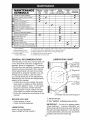
MAINTENANCE
SCHEDULE
EVERY
BEFORE
A
FTEREVERY
EACH
EACH
10
25HOURS
use USE HOURS
OR SEASON
Check for Loose Fasteners
,_ Clean / Inspect Grass Catcher *
_
Check Tires
Check
Drive Wheels ***
Clean Lawn Mower****
t_
I/
i/
I/
_1_
i/
i/
i/3
i/
i/
O Check Drive Belt / Pulleys ***
W Check / Sharpen / Replace Blade
ubrication
Clean and Recharge Battery **
1_,2
14
I/
_ Inspect Muffler
N Replace Spark Plug
I1= Replace Air Filter Paper Cartridge
Empty fuel system or add Stabilizer
* (if so equipped)
mowers
*** Power-Propelled
mowers
**** Use a scraper
to clean under deck
GENERAL
14
14
Check Engine Oil level
E Change Engine Oil
N Clean Air Filter
** Electric-Start
BEFORE
STORAGE
t/
t/
M Clean under Drive Cover ***
_
EVERY
100
HOURS
1
2
3
4
5
-
I/
14
I/
Change more often if operating under a heavy load or in high outdoor
Service more often if operating in dirty or dusty conditions.
Replace blades more often when mowing in sandy soil.
Charge 48 hours at end of season.
And after each 5 hours of use.
LUBRICATION
RECOMMENDATIONS
The warranty on this lawn mower does not
cover items that have been subjected to
operator abuse or negligence. To receive
ful! value from the warranty, operator must
maintain unit as instructed in this manual.
Some adjustments wil! need to be made
periodically to properly maintain your unit.
At least once a season, check to see if
you should make any of the adjustments
described in the Service and Adjustments
section of this manual.
• At least once a year, replace the spark
plug, clean or replace air filter element
and check blade for wear. A new spark
plug and clean/new air filter element
assure proper air-fuel mixture and help
your engine run better and last longer.
• Follow the maintenance schedule in this
manual.
temperatures.
CHART
Wheel
adjuster (on
each wheel)
Engine oil
(_ Mulcher
door hinge
pin
(_ Rear
door hinge
(_ Handle bracket mounting pins
(_) Spray lubricant
BEFORE EACH USE
• Check engine oil level.
• Check for loose fasteners.
(_) See "ENGINE"
in Maintenance
section.
IMPORTANT:
Do not oil or grease plastic
wheel bearings.
Viscous lubricants will
attract dust and dirt that will shorten the life of
the self-lubricating bearings. If you feel they
must be lubricated, use only a dry, powdered
graphite type lubricant sparingly.
LUBRICATION
Keep unit well lubricated
(See "LUBRICATION CHART").
12
LAWN MOWER
Always observe safety rules when performing any maintenance.
3. Be sure the trailing edge of blade (opposite sharp edge) is up toward the
engine.
4. Install the blade bolt with the lock
washer and hardened washer into
blade adapter and crankshaft.
5. Use block of wood between blade and
lawn mower housing and tighten the
blade bolt, turning clockwise.
• The recommended tightening torque is
35-40 ft. Ibs.
IMPORTANT:
Blade bolt is heat treated.
If bolt needs replacing, replace only with
approved bolt shown in the Repair Parts
section of this manual.
TIRES
• Keep tires free of gasoline, oil, or insect
control chemicals which can harm rubber.
• Avoid stumps, stones, deep ruts, sharp
objects and other hazards that may
cause tire damage.
DRIVE WHEELS
Check rear drive wheels each time before
you mow to be sure they move freely.
The wheels not turning freely means trash,
grass cuttings, etc. are in the drive wheel area
and must be cleaned to free drive wheels.
If necessary to clean the drive wheels, be
sure to clean both rear wheels.
Blade adapter
Key
Crankshaft
Lockwasher
Blade
BLADE
CARE
For best results, mower blade must be
kept sharp. Replace a bent or damaged
blade.
& CAUTION:
Use only a replacement
blade approved by the manufacturer of
your mower. Using a blade not approved
by the manufacturer of your mower is hazardous, could damage your mower and
void your warranty.
TO REMOVE
Blade
bolt
Hardened
washer
retainer
TO SHARPEN BLADE
NOTE: We do not recommend sharpening blade - but if you do, be sure the
blade is balanced. An unbalanced blade
will cause eventual damage to lawn
mower or engine.
• The blade can be sharpened with a file
or on a grinding wheel. Do not attempt
to sharpen while on the mower.
• To check blade balance, you will need
a 5/8" diameter steel bolt, pin, or a cone
balancer. (When using a cone balancer,
follow the instructions supplied with
balancer.)
NOTE: Do not use a nail for balancing
blade. The lobes of the center hole may
appear to be centered, but are not.
• Slide blade on to an unthreaded portion
of the steel bolt or pin and hold the
bolt or pin parallel with the ground. If
blade is balanced, it should remain in a
horizontal position. If either end of the
blade moves downward, sharpen the
heavy end until the blade is balanced.
BLADE
1. Disconnect spark plug wire from spark
plug and place wire where it cannot
come in contact with plug.
2. Turn lawn mower on its side. Make
sure air filter and carburetor are up.
3. Use a wood block between blade and
mower housing to prevent blade from
turning when removing blade bolt.
NOTE: Protect your hands with gloves
and/or wrap blade with heavy cloth.
4. Remove blade bolt by turning counterclockwise.
5. Remove blade and attaching hardware (bolt, lock washer and hardened
washer).
NOTE: Remove the blade adapter and
check the key inside hub of blade adapter.
The key must be in good condition to work
properly. Replace adapter if damaged.
TO REPLACE BLADE
1. Position the blade adapter on the engine crankshaft. Be sure key in adapter
and crankshaft keyway are aligned.
2. Position blade on the blade adapter.
IMPORTANT: To ensure proper assembly,
center hole in blade must align with star
on blade adapter.
....
Trailing/ed_ge '
Center hole
5/8" bolt or pin
13
Blade
GRASS CATCHER
• The grass catcher may be hosed with
water, but must be dry when used.
• Check your grass catcher often for damage or deterioration.
Through normal
use it will wear. If catcher needs replacing, replace only with approved replacement catcher shown in the Repair Parts
section of this manual. Give the lawn
mower model number when ordering.
1. Disconnect spark plug wire from spark
plug and place wire where it cannot
come in contact with plug.
2. Remove oil fil! cap/dipstick; lay aside
on a clean surface.
3. Tip lawn mower on its side as shown
and drain oil into a suitable container.
Rock lawn mower back and forth to remove any oil trapped inside of engine.
GEAR CASE
• To keep your drive system working
properly, the gear case and area around
the drive should be kept clean and free
of trash build-up. Clean under the drive
cover twice a season.
• The gear case is filled with lubricant to the
proper level at the factory. The only time
the lubricant needs attention is if service
has been performed on the gear case.
4. Wipe off any spilled oil from lawn
mower or side of engine.
5. Fill engine with oil. Slowly pour oil
down the oil fil! spout into the engine.
6. Wait one minute to allow oil to settle.
Use guage on oil fill cap/dipstick for
checking level. Insert dipstick into
the tube and rest the oil fill cap on the
tube. DO NOT thread the cap into the
tube when taking reading.
ENGINE
Maintenance, repair, or replacement of the
emission control devices and systems, which
are being done at the customers expense,
may be performed by any non-road engine
repair establishment or individual. Warranty
repairs must be performed by an authorized
engine manufacturer's service outlet.
LUBRICATION
Oil fill cap /
dipstick
Use only high quality detergent oi! rated
with API service classification
SG-SL.
Selectthe oil's SAE viscosity grade according
to your expected operating temperature.
SAE VISCOSITY GRADES
Uppe
°F
-20
°c -_o
0
.2;
TEMPERATURE
30
-_;
RANGE
32
40
;
ANTICIPATED
60
1;
BEFORE
80
_o
mark-_
Lower"
100
1o
4O
mark
NEXT OIL CHANGE
NOTE: Multi-viscosity oils (5W30, 10W30
etc.) improve starting in cold weather, and
you should check your engine oil level frequently to avoid possible engine damage
from running low on oil.
Change the oil after every 25 hours of
operation or at least once a year if the
lawn mower is not used for 25 hours in
one year.
Check the crankcase oil level before
starting the engine and after each five (5)
hours of continuous use. Tighten oil plug
securely each time you check the oil level.
TO CHANGE ENGINE OIL
NOTE: Before tipping lawn mower to
drain oil, empty fuel tank by running engine until fuel tank is empty.
7. Continue adding small amounts of
oil and rechecking the dipstick until it
reads ful!. DO NOT overfill, or engine
will smoke on startup.
8. Always be sure to retighten oil fill cap/
dipstick before starting engine.
9. Reconnect spark plug wire to spark
plug.
AIR FILTER
14
Your engine will not run properly and may
be damaged by using a dirty air filter.
Replace the air filter every 100 hours of
operation or every season, whichever occurs first. Service air cleaner more often
under dusty conditions.
TO CLEANAIR FILTER
1. Remove cover.
2. Carefully remove cartridge.
3. Clean by gently tapping on a flat surface. If very dirty, replace cartridge.
ACAUTION: Petroleum solvents, such as
kerosene, are not to be used to clean cartridge. They may cause deteriorationof the
cartridge. Do not oil cartridge. Do not use
pressurizedair to clean or dry cartridge.
4. Install cartridge,then replace cover.
Tab
Cartridge
Filter
MUFFLER
Inspect and replace corroded muffler as it
could create a fire hazard and/or damage.
SPARK PLUG
Replace spark plug at the beginning of
each mowing season or after every 100
hours of operation, whichever occurs first.
Spark plug type and gap setting are shown
in the "PRODUCT SPECIFICATIONS"
section of this manual.
CLEANING
IMPORTANT:
For best performance, keep
mower housing free of built-grass and
trash. Clean the underside of your mower
after each use.
,ACAUTION:
Disconnect spark plug wire
from spark plug and place wire where it
cannot come in contact with spark plug.
• Clean the underside of your lawn mower
by scraping to remove build-up of grass
and trash.
• Clean engine often to keep trash from
accumulating.
A clogged engine runs
hotter and shortens engine life.
• Keep finished surfaces and wheels free
of all gasoline, oil, etc.
• We do not recommend using a garden
hose to clean lawn mower unless the
electrical system, muffler, air filter and
carburetor are covered to keep water
out. Water in engine can result in shortened engine life.
15
WATER
WASHOUT
FEATURE
Your lawn mower is equipped with a fitting
that allows quick and easy cleaning of
the underside of the housing. To use this
feature, proceed as follows:
1. Move lawn mower to an area of cut
grass or another hard surface.
NOTE: Water, grass and other debris will
drain from beneath the mower housing
during the washout process.
2. Remove grass catcher and discharge
chute assembly from lawn mower.
3. Close mulcher door (if equipped).
4. Connect a garden hose to the fitting
where shown.
IMPORTANT:
Be sure the garden hose is
not routed under the lawn mower housing
or entangled in the wheels.
5. Turn on water supply and check for
leaks at the fitting.
If no leaks are present, start engine (as
described in the Operation section of
this manual) and let engine run until the
underside of the lawn mower is clean.
A WARNING:
Do not engage the drive
system during the washout process.
6. Shut off the engine.
7. Shut off water supply and remove
hose from fitting.
CAUTION: Do not remove hose from
fitting while engine is running. Water in
engine can result in shortened engine life.
8. Start engine (as described in the Operation section of this manual) and let
engine run for a full minute to remove
excess water from mower.
Hose
Fitting
CLEAN UNDER DRIVE COVER
Clean under drive cover at least twice a
season. Scrape underside of cover with
putty knife or similar tool to remove any
build-up of trash or grass on underside of
drive cover.
A
1.
2.
3.
WARNING: To avoid serious injury,before performingany service and adjustments:
Release control bar and stop engine.
Make sure the blade and all moving parts have completely stopped.
Disconnect spark plug wire from spark plug and place wire where it cannot come in
contact with plug.
LAWN
MOWER
6. Reinstall belt keeper and drive cover.
NOTE: Always use factory approved belt
to assure proper fit and long life.
TO ADJUST CUTTING HEIGHT
See "TO ADJUST CUTTING HEIGHT" in
the Operation section of this manual.
REAR
Blade adapter
Key
Crankshaft
DEFLECTOR
Lockwasher
The rear deflector, attached between the
rear wheels of your mower, is provided to
minimize the possibility that objects will
be thrown out of the rear of the mower
into the operator mowing position. If the
deflector becomes damaged, it should be
replaced.
TO REMOVE
Blade
Blade
bolt
Hardened
washer
DRIVE BELT
1. Remove drive cover and belt keeper.
2. Remove belt from gearcase pulley.
3. Turn lawn mower on its side with air
filter and carburetor down.
4. Remove blade and blade adapter.
5. Remove belt from engine pulley.
i,:
....
,
Trailing/ed_ge
retainer
TO ADJUST HANDLE
Your handle has three (3) height positions
- adjust to a height that suits you.
1. Remove knob and carriage bolt on one
side of the lower handle.
2. While holding handle assembly,
remove knob and carriage bolt from
opposite side, align hole in handle with
desired hole in handle bracket and
reassemble bolt and knob and tighten
securely.
3. Align opposite side of handle with
same positioning hole and secure with
bolt and knob.
Drive
cover
\
Gearcase
pulley
Handle
bracket
Belt
3er
Knob
J
TO REPLACE
Belt
DRIVE
Bolt
BELT
1. Place new drive belt on engine pulley,
inside tabs of belt retainer.
2. Route the other end of the new drive
belt through hole in housing.
3. Reinstall blade adapter and blade.
4. Return mower to upright position.
5. Install new belt on gearcase pulley.
16
ENGINE
CARBURETOR
Maintenance, repair, or replacement of the
emission control devices and systems, which
are being done at the customers expense,
may be performed by any non-road engine
repair establishment or individual. Warranty
repairs must be performed by an authorized
engine manufacturer's service outlet.
ENGINE SPEED
Your carburetor is not adjustable. If your
engine does not operate properly due
to suspected carburetor problems, take
your lawn mower to a Sears or other
qualified service center for repair and/or
adjustment.
IMPORTANT:
Never tamper with the
engine governor, which is factory set for
proper engine speed. Overspeeding
the engine above the factory high speed
setting can be dangerous. If you think
the engine-governed high speed needs
adjusting, contact a Sears or other
qualified service center, which has proper
equipment and experience to make any
necessary adjustments.
Your engine speed has been factory set.
Do not attempt to increase engine speed
or it may result in personal injury. If you
believe that engine is running too fast or
too slow, take your mower to a Sears or
other qualified service center for repair
and adjustment.
Immediately prepare your lawn mower for storage at the end of the season or if the unit
will not be used for 30 days or more.
LAWN MOWER
When lawn mower is to be stored for a
period of time, clean it thoroughly, remove
all dirt, grease, leaves, etc. Store in a
clean, dry area.
1. Clean entire lawn mower (See
"CLEANING" in the Maintenance section of this manual).
2. Lubricate as shown in the Maintenance
section of this manual.
3. Be sure that all nuts, bolts, screws, and
pins are securely fastened. Inspect
moving parts for damage, breakage
and wear. Replace if necessary.
4. Touch up all rusted or chipped paint
surfaces; sand lightly before painting.
HANDLE
You can fold your handle for storage.
1. Loosen the two (2) handle knobs on
sides of the upper handle and allow
handle to fold down to the rear.
2. Remove the two (2) handle knobs and
carriage bolts on sides of the lower handle
and pivot entire handle assembly forward
and allow it to rest on mower.
3. Reinstall knobs and carriage bolts to
lower handle / handle brackets for safe
keeping.
• When setting up your handle from
the storage position, lower handle will
require manually locking into mowing
position.
IMPORTANT:
When folding the handle
for storage or transportation, be sure to
fold the handle as shown or you may damage the control cables.
MOWING
POSITION
Operator
control bar
/////
FOLD
FORWARD
FOR
STORAGE
/
Upper
handle
/
Handle
knob
Lower handle
Handle
bracket
Knob
Bolt
17
ENGINE
ENGINE OIL
FUEL SYSTEM
Drain oi! (with engine warm) and replace
with clean engine oil. (See "ENGINE" in
the Maintenance section of this manual).
IMPORTANT:
It is important to prevent
gum deposits from forming in essential fuel
system parts such as carburetor,
fuel filter,
fuel hose, or tank during storage. Alcohol
blended fuels (called gasohol or using
ethanol or methanol)
can attract moisture
which leads to separation
and formation
of acids during storage. Acidic gas can
damage the fuel system of an engine while
in storage.
CYLINDER
1. Remove spark plug.
2. Pour one ounce (29 ml) of oil through
spark plug hole into cylinder.
3. Pull starter handle slowly a few times
to distribute oil.
4. Replace with new spark plug.
• Empty the fuel tank by starting the engine and letting it run until the fuel lines
and carburetor
are empty.
• Never use engine or carburetor
cleaner
products in the fuel tank or permanent
damage may occur.
• Use fresh fuel next season.
OTHER
, Do not store gasoline from one season
to another.
• Replace your gasoline can if your can
starts to rust. Rust and/or dirt in your
gasoline will cause problems.
, If possible, store your unit indoors and
cover it to protect it from dust and dirt.
, Cover your unit with a suitable protective cover that does not retain moisture.
Do not use plastic. Plastic cannot
breathe, which allows condensation to
form and will cause your unit to rust.
IMPORTANT:
Never cover mower while
engine and exhaust areas are still warm.
_I_CAUTION: Never store the lawn
mower with gasoline in the tank inside a
building where fumes may reach an open
flame or spark. Allow the engine to cool
before storing in any enclosure.
NOTE: Fuel stabilizer is an acceptable
alternative
in minimizing
the formation
of
fuel gum deposits during storage.
Add
stabilizer to gasoline in fuel tank or storage container.
Always follow the mix ratio
found on stabilizer container.
Run engine
at least 10 minutes after adding stabilizer
to allow the stabilizer to reach the carburetor.
Do not empty the gas tank and
carburetor
if using fuel stabilizer.
TROUBLESHOOTING
= See appropriate
to a Sears Parts & Repair Centre.
PROBLEM
CAUSE
Does
not start
section
in manual
unless
directed
CORRECTION
Dirty air filter.
2. Out of fue!.
3. Stale fuel.
.
Clean/replace air filter.
2. Fill fuel tank.
3. Empty fuel tank and refill tank
with fresh, clean gasoline.
4. Empty fuel tank and refill tank
with fresh, clean gasoline.
5. Connect wire to plug.
.
4. Water in fuel.
5. Spark plug wire is
disconnected.
6. Bad spark plug.
7. Loose blade or broken
blade adapter.
8. Control bar in released
position.
9. Control bar defective.
10. Fuel valve lever (if so
equipped) in OFF position.
11. Weak battery (if equipped).
12. Disconnected battery
connector (if equipped).
13. Blown fuse (if equipped).
18
6. Replace spark plug.
7. Tighten blade bolt or
replace blade adapter.
8. Depress control bar to
handle.
9. Replace control bar.
10. Turn fuel valve lever
to the ON position.
11. Charge battery.
12. Connect battery to engine.
13. Replace fuse.
TROUBLESHOOTING
= See appropriate
to a Sears Parts & Repair Centre.
PROBLEM
CAUSE
Loss of power
Poor cut -
section in manual
1. Rear of lawn mower
housing or cutting blade
dragging in heavy grass.
2. Cutting too much grass.
3. Dirty air filter.
4. Buildup of grass, leaves,
and trash under mower.
5. Too much oil in engine.
6. Walking speed too fast.
1. Worn, bent or loose blade.
urleveR
2. Wheel heights uneven.
3. Buildup of grass, leaves
and trash under mower.
Excessive
vibration
1. Worn, bent or loose blade.
2. Bent engine crankshaft.
Starter rope
hard to pull
.
.
Engine flywheel brake is on
when control bar is released.
Bent engine crankshaft.
3. Blade adapter broken.
4. Blade dragging in grass.
unless directed
CORRECTION
1. Raise cutting height.
2. Raise cutting height.
3. Clean/replace air filter.
4. Clean underside of mower
housing.
5. Check oi! level.
6. Cut at slower walking speed.
1. Replace blade. Tighten
blade bolt.
2. Set all wheels at same
height.
3. Clean underside of
mower housing.
1. Replace blade. Tighten
blade bolt.
2. Contact a Sears or other
qualified service centre.
1. Depress control bar to
upper handle before
pulling starter rope.
2. Contact a Sears or other
qualified service centre.
3. Replace blade adapter.
4. Move lawn mower to cut
grass or to hard surface.
Grass catcher
not filling
(if so equipped)
1. Cutting height too low.
2. Lift on blade worn off.
3. Catcher not venting air.
1. Raise cutting height.
2. Replace blade.
3. Clean grass catcher.
Hard to push
1. Grass is too high or wheel
height is too low.
2. Rear of lawn mower
housing or cutting blade
dragging in grass.
3. Grass catcher too full.
4. Handle height position not
right for you.
1. Raise cutting height.
Loss of drive
or slowing of
drive speed
1.
2.
3.
4.
Belt wear.
Belt off of pulley.
Drive cable worn or broken.
"Loose" drive control system.
19
2. Raise rear of lawn mower
housing one (1) setting
higher.
3. Empty grass catcher.
4. Adjust handle height to suit.
1.
2.
3.
4.
Check/replace drive belt.
Check/reinstal! drive belt.
Replace drive cable.
Adjust drive control.
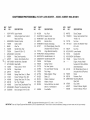
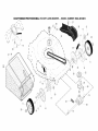
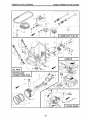
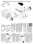
CRAFTSMAN
PROFESSIONAL
ROTARY
LAWN MOWER-
- MODEL NUMBER
944.36t
36t
58
64
27
3
39
34
22
63
i
12
!
19
25
I
9
28
!
55
0
22
47
\52\
48
31
50
35
/
36
42
51
!jl
.....32
41
43
44
CRAFTSMAN
KEY
NO.
PART
NO.
PROFESSIONAL
DESCRIPTION
1
2
183471X479
438391
3
4
5
6
7
8
429930X004
145006
66426
182398
750634
426432X428
Upper Handle
Cable, Engine Zone Control/
Rear Door Prop
Bracket, Upstop
Guide, Cable
Wire Tie
Handle Knob, Star
Screw #10-24 x 112
Control Bar
430654
425575
189713X428
427120X428
Rear Door Assembly
Hairpin, Door/Handle Pivot
Handle Knob, Standard
Rear Baffle
18
19
20
132004
194788
429157
Keps Locknut
Rope Guide
Rear Skirt
21
22
24
25
26
419949
141841
419948
409148
419945
27
28
400246X460
72250505
9
11
_O
--_ 12
17
IMPORTANT:
ROTARY
KEY
NO.
PART
NO.
30
31
32
33
34
35
413808
419407X615
419944X007
420019
419946X615
431127
36
38
LAWN MOWER-
- MODEL NUMBER
DESCRIPTION
KEY
NO.
944.361361
PART
NO.
52
53
404763
17000510
55
56
191730
17411312
175735
419942X428
Nut, Push
Selector Knob
Latch, Mulcher Door
Mulcher Door
Bracket, Grassbag
Kit, Wheel Adjuster, Rear, RH
(Includes Knob & Pushnut)
Hinge Bracket Assembly
Discharge Deflector
57
58
59
155377
421241X479
191574
39
40
41
42
442470X479
438526X479
150406
193000
Handle Bracket, LH
Handle Bracket, RH
Bolt, Engine
Spring, Torsion
62
63
64
431913X004
178848
---
43
44
45
191730
431558
175650
Nut, Hex, Nylock
Kit, Lawn Mower Housing
Rod, Hinge
68
431129
Spring, Rear Door, LH, Black
Screw, Panhead, Torx #20
Spring, Rear Door, RH, Grey
Nut, Hex, Flanged
Screw, Rear Door/Handle Pivot
46
47
48
49
50
421782
421825
851074
850263
851084
Blade Adapter/Pulley
Blade, 22"
Washer, Hardened
Washer, Helical
Screw, Machine, Hex Head
83
84
85
750097
428124
429801X004
96
Wheel & Tire Assembly, Rear
Bolt, Carriage 5116-18 x 518
51
430599
3/8-24 x 1-3/8 Grade 8
Front Baffle
---
197991
443307
443308
1/4-20
DESCRIPTION
Decal, Danger
Screw, Semi-Gimlett Point
1/4-20 x 1/2
Nut, Hex
Screw, Hex Washer Head
#13 x 3/'4
Nut, Hex
Lower Handle
Handle Bolt
Belt Retainer
Screw #10-16 x 5t8
Engine, Honda, Model
Number GCV160-LAOS3A
(See Breakdown)
Kit, Wheel Adjust, Rear, LH
(Includes Knob & Pushnut)
Screw
Fastener, Push
Mounting Bracket,
Rear Skirt
Clip, Cable
Owner's Manual, English
Owner's Manual, French
NOTE: All component dimensions given in U.S. inches. 1 inch = 25.4 mm.
Use only Original Equipment Manufacturer (O,E,M) replacement parts, Failure to do so could be hazardous, damage your lawn mower and void your warranty,
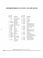
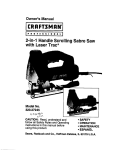
CRAFTSMAN
PROFESSIONAL
ROTARY
LAWN MOWER-
/
- MODEL NUMBER
944.36t
36t
27
_/P\\
81 82 "'"
-...
C_ _
/
28
83i
/
\
29
\
1
- @-
\\ 9
20
57
54
\
11
1
29
...........
36
16
CRAFTSMAN
KEY
NO.
PO
IMPORTANT:
PROFESSIONAL
PART
NO.
ROTARY
LAWN MOWER-
DESCRiPTiON
KEY
NO.
PART
NO.
Drive Control Assembly
(Includes Cable)
Cable, Drive
28
29
32
428165
409148
194018
1
431508
9
431649
10
429544X479
Mounting Bracket,
Drive Control
33
35
426609
431124
11
12
13
14
15
194231X460
12000058
403849
189403
404845
Wheel & Tire Assembly
E-Ring
Pinion
Dust Cover
Pawl, Drive
36
38
40
41
424657
191730
406558
431121
16
17
18
20
25
67725
413808
419345X615
181698
430458X004
Washer, Flat 3t8
Nut, Push
Selector Knob
Screw
Belt Guide Bracket
54
57
80
422506
419951
421114
26
163409
27
175262
Screw, Hi-Lo Thread
#12 x 518
Screw, Pan Head
#10-24 x 2-3/4
81
82
83
419735
415585
415586
- MODEL NUMBER
944.361361
DESCRiPTiON
Drive Cover
Locknut, Hex
Drive Pulley
V-Belt
Kit, Wheel Adjuster, Front, LH
(Includes Knob and Pushnut)
Gearcase Assembly, Complete
Locknut, Hex 1/'4-20
Spring
Kit, Wheel Adjuster, Front, RH
(Includes Knob and Pushnut)
Grassbag
Frame, Grassbag
Kit, Water Washout Assembly
(Includes Key Numbers 81 thru 83)
Fitting, Water Washout
Washer, Lock, Internal Tooth
Locknut, Hex, with O-Ring
NOTE: All component dimensions given in U.S. inches. 1 inch = 25.4 mm.
Use only Original Equipment Manufacturer (O,E,M.) replacement parts, Failure to do so could be hazardous, damage your lawn mower and void your warranty,
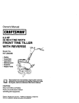
HONDA 4-CYCLE
ENGINE
CYLINDER BARREL
MODEL NUMBER
!
GCV160-LAOS3A
CRANKSHAFT
/
®
3tS-24UNF
_:
2B TAP
--135.7-_86.7
L_" .
CARBURETOR l
15_
^,_4
_
_
14
o.,,.W._;_,/
,
M " ,o
,_,
,_o<. ,_!
--_
-29_7_,<...,_
.......
21_
28
2_p
"o/_
.o_
]
_-"7 :__
,_,
___-__j
-'i
_2
{_"
_
.
-24
,
L_w/
,
23
@_,
....
RECOIL
11J=_l.i/'I
STARTER
-_-_--
]
_ .........
_
__
"
L____
24
_-__ ....
i
HONDA 4-CYCLE
ENGINE
MODEL NUMBER
CYLIND£R
BARR£L
KEY
PART
NO.
NO.
DESCRIPTION
1 12000-ZOL-406
Cylinder Assembly
12000-ZOL-840
Cylinder Assembly
3 12310-ZOJ-000
Cover, Cylinder Head
12311-ZL8-D00
Cover, Head
12311-ZL8-000
Cover, Head
4 12355-ZL8-000
Cover, Breather
5 90013-883-000
6 90014-952-000
7 91201-ZL8-003
8 98079-55846
10 12209-ZM0-003
11 14711-ZL8-000
14711-ZOJ-000
14711-ZOJ-800
12 14721-ZL8-000
13 14751-ZL8-000
14 14771-ZOJ-000
CARBURETOR
KEY
PART
NO.
NO.
1 16010-883-015
2 16013-ZLI-003
3 16015-ZOL-881
5 16028-ZE0-005
16028-ZK7-$91
7 16100-ZOL-852
8
9
10
11
13
15
16
16155-ZM0-013
16166-ZM0-003
16211 -ZL8-000
16212-ZL8-000
16228-ZL8-000
93500-05006-0H
99101-124-0600
99101-124-0620
99101-124-0650
26 16951-ZOL-000
CONTROL
KEY
PART
NO.
NO.
1
2
3
4
10
13
15
(Breather Valve Assembly)
Bolt, Flange (#6 x 12)
(CT200)
Bolt, Flange (#6 x 14)
(CT200)
Oil Seal (25.4 x 62 x 6)
Spark Plug (BPR5ES)
(NGK)
Seal, Valve Stem
Valve, Intake
(Technostar)
Valve, Intake (Rocknel)
Valve, Intake
Valve, Exhaust
16551-ZM0-010
16555-ZOL-801
16561-ZOL-000
16562-ZM0-000
90015-ZE5-010
94050-06000
93892-04012-00
GCV160=LAOS3A
DESCRIPTION
16 94103-04000
Arm, Governor
Rod, Governor
Spring, Governor
Spring, Throttle Return
Bolt, Governor Arm
Nut, Flange (6 mm)
Screw, Washer Head
(#4 x 12)
Washer, Plain (4 mm)
CRANKSHAFT
KEY
PART
NO.
NO.
3 13310-ZM0-610
DESCRIPTION
Crankshaft
5 90402-ZL8-000
Washer, Thrust
RECOIL STARTER
KEY
PART
NO.
NO.
DESCRIPTION
1 28400-ZOL-V20ZA
Spring, Valve
Retainer, Valve Spring
8 28461-ZL8-003
9 28462-ZOL-V20
DESCRIPTION
Gasket Set
Float Set
Chamber Set, Float
Screw Set
Screw Set
11 90201-ZM0-000
Carburetor Assembly
(Ba62z B)
Valve, Float
Nozzle, Main
Insulator, Carburetor
Gasket, Insulator
Gasket, Carburetor
Screw, Pan (#5 x 6)
Jet, Main (#60)
Jet, Main (#62)
Jet, Main (#65)
Guide, Air
25
Starter Assembly,
Recoil, "NHI" (Long Rope)
(Black)
Grip, Recoil Starter
Rope, Recoil Starter,
"Long Type" (Black)
Nut, Flange (6 ram)
HONDA 4-CYCLE
ENGINE
MODEL NUMBER
GCV160-LAOS3A
/
9
] _15
®
21
14
- 27
48
@1o
11
47
49
33
8
E.t4
40
FAN COVER
i
2
26
AIR CLEANER
]
2
I
3
7
26
HONDA 4-CYCLE
ENGINE
MODEL NUMBER
FAN COVER
KEY
PART
NO.
NO.
DESCRIPTION
6 16950-ZOY-003
Petcock Assembly
7 16952-ZA8-800
Filter, Fuel
8 16961-ZOL-900
Stay, Fuel Petcock
9 17511-ZOL-030
Tank, Fuel
10 17514-ZOL-000
Seal, Fuel Filler Neck
11 17518-ZOL-000
Clip, Tank Mounting
12 17532-ZOL-000
Rubber A, Tank Mounting
13 17533-ZOL-000
Rubber B, Tank Mounting
14 17534-ZOL-000
Nut, Tank Mounting
15 17620-ZOJ-800
Cap Assembly, Fuel Tank
16 17636-ZOL-000
Gauge, Fuel Level
21 19610-ZOL-861 ZC
Cover Assembly, Fan
"T89" (Craftsman Red)
19610-ZOL-861 ZA
Cover Assembly, Fan
"T89" ("NHI")(Black)
19610-ZOL-861 ZD
Cover Assembly, Fan
"T93" (Husqvarna Grey)
19610-ZOL-861 ZE
Cover Assembly, Fan
"T98" (M.T.D. Red)
22 19619-ZL8-300
Collar, Fan Cover
24 90013-883-000
Bolt, Flanged (#8 x 12)
25 90015-883-000
27 90043-ZL8=000
28 90043-ZL8-000
33 93913-25220
FLYWHEEL
KEY
PART
NO.
NO.
1 13331-357-000
3
4
5
6
8 75113-ZM0-000
10 90014-952-000
11 90018-ZE1-000
12 90018-ZE1-000
13 90201-Z0%800
14 51125-ZOL-003
90681-959-003
15 93892-04012-00
16 94103-04000
21 75110-ZOY-000
25 91601-ZOL-300
(CT200)
Bolt, Flanged (#8 x 28)
(CT200)
Bolt, Stud (H=42.5mm)
Bolt, Stud (H=42.5mm)
Screw, Tapping (PO)
AIR CLEANER
KEY
PART
NO.
NO.
1 15721-ZM0-000
2 17211-ZL8-023
3 17220-ZM0-010
(#5 x 12)
35
36
40
42
91424-Z8B-821
91427-Z8B-821
95002-40800-08
95002-41200-08
MUFFLER
KEY
PART
NO.
NO.
1 18310-ZM0-000
2 18321-ZOL-J00
18321-ZOL-J01
3 90004-ZL8-000
4 90013-883-000
5
9
10
11
12
18381-ZL8-305
18350-ZL8-000
18356-ZL8-000
90055-ZE1-000
06180-ZOJ-000
Tube, Fuel
Tube, Fuel
Clip, Tube
Clip, Tube
30500-ZL8-014
31105-ZM0-000
32195-ZM0-800
35120-ZM0-003
Tank
(7.3 x 160)
(D8)
(D12)
17220-ZM0-020
17220-ZM0-030
DESCRIPTION
Muffler
5 17228-ZM0-000
6 17231-ZOL-030
Protector, Muffler
(S/N 1243452 and below)
Protector, Muffler
17231-ZOL-040
17231-ZOL-050
7 90003-ZM0-010
(S/N 1243453 and above)
Bolt, Flange #6 x 79
(CT200)
Bolt, Flange #6 x 12
(CT200)
Gasket, Muffler
Arrester, Spark
Plate, Arrester Number
Screw, Tapping #4 x 6
Kit, Spark Arrester
27
GCV160=LAOS3A
DESCRIPTION
Key, Special, Woodruff
(25 x 18)
Coil Assembly, Ignition
Flywheel Assembly
Wire, Stop Switch
Switch Assembly,
Engine Stop (NC)
Spring, Brake Lever
Bolt, Flange (#6 x 14)
(CT200)
Bolt, Flange (#8 x 23)
(CT200)
Bolt, Flange (#6 x 23)
(CT200)
Nut, Special (14 mm)
Holder, Wire (Fastex)
Clip A, Cable (3.8mm)
(Black) (NIFCO)
Screw, Washer Head
(#4 x 12)
Washer, Plain (4 mm)
Brake Sub Assembly
Grommet, Brake Plate
DESCRIPTION
Tube, Breather
Element, Air Cleaner
Case Assy., Air Cleaner
(SIN 1167575 and below)
Case Assy., Air Cleaner
(SIN 1167576-1239013)
Case Assy., Air Cleaner
(SIN 1239014 and above)
Gasket, Air Cleaner
Cover, Air Cleaner
(SIN 1167575 and below)
Cover, Air Cleaner
(SIN 1167575 and below)
Cover, Air Cleaner
Bolt, Flange (#6 x 85)
(CT200)
HONDA 4-CYCLE
ENGINE
MODEL NUMBER
GCV160-LAOS3A
,
I
i
I
i
i
I
I
I
I
_
> ;i i
13_
15
CONNECTING
L__
---
ROD
--o
3
/
I
_W-%%_,,1
_
<J __-_
28
.........................
I
CAMSHAFT
I _/_
PULLEY
_._;i_--o-
CHOKESASE
HONDA 4-CYCLE
ENGINE
MODEL NUMBER
CAMSHAFT
PULLEY
KEY
PART
NO.
NO.
DESCRIPTION
1 14320-ZL8-010
Pulley, Camshaft
2 14324-ZL8-000
Shaft, Cam Pulley
3 14400-ZOJ-014
Belt, Timing
6
11
12
13
15
16
14461-ZL8-000
90112-333-000
90206-001-000
91301-ZM0-V31
14431-ZOJ-000
14441-ZOJ-000
OIL PAN
KEY
PART
NO.
NO.
1 11300-ZM0-811
2 15650-ZM0-801
4
5
6
8
9
10
11
12
13
14
15
15625-ZE6-000
15631-ZM0-000
15639-ZM0-000
16508-ZM0-010
16510-ZM0-010
16511-ZL8-000
16512-ZM0-000
16513-ZEI-000
16531-ZE1-000
16541-ZM0-000
90014-952-000
16 90121-952-000
17
18
19
20
21
22
23
90451-ZEI-000
90602-ZE1-000
91202-ZL8-003
91356-MA6-005
94101-068000
94251-08000
94301-08200
GCV160=LAOS3A
PISTON / CONNECTING
ROD
KEY
PART
NO.
NO.
DESCRIPTION
1 13101-Z2A-010
Piston
2 13111-ZE0-000
Pin, Piston
3 13200-ZOJ-000
Connecting Rod Assembly
4 90001-ZEI-000
Bolt, Connecting Rod
5 90551-ZE0-000
Clip, Piston Pin (13 mm)
6 13010-ZOL-014
Ring Set, Piston, Standard
(84HU7 G-200)
Shaft, Rocker Arm
Screw, Tappet Adjusting
Nut, Tappet Adjusting
O-Ring (6.8 x 1.9) (ARAI)
Rocker Arm, Intake Valve
Rocker Arm,
Exhaust Valve
(Teikoku)
LABELS
KEY
PART
NO.
NO.
9
20
30
31
32
DESCRIPTION
Pan Assembly, Oil
Gauge Assembly,
Oil Level
87528-ZOL-V20
87114-ZH7-821
87101-Z8B-000
87169-Z8E-000
87524-Z8B-000
CHOKE BASE
KEY
PART
NO.
NO.
2 16592-Z2D-800
5 16614-Z2D-800
8 16632-ZOL-801
9 90022-888-010
Gasket, Oil Filler Cap
Extension, Oil Filler
Lock Washer, Extension
Shaft, Governor Holder
Governor Assembly
Weight, Governor
Holder, Governor Weight
Pin, Governor Weight
Slider, Governor
Shaft, Governor Arm
14 16610-Z2D-801
16610-Z2D-802
Bolt, Flange (#6 x 14)
(CT200)
Bolt, Flange (#6 x 25)
(CT200)
Washer, Thrust (6 mm)
Clip, Governor Holder
Oil Seal (28 x 41.25 x 6)
O-Ring (14.8 x 2.4) (NOK)
Washer, Plain (6 mm)
Pin, Lock (8 mm)
Pin, Dowel (#8 x 20)
29
DESCRIPTION
Mark, Choke Indication
Label, Warning
Mark, Emblem (GCV160)
Mark, Recoil Cover
Mark, Caution,
Fuel Petcock
DESCRIPTION
Spring, Return
Spring, Choke Lever
Rod, Stop
Bolt, Flange (#6 x 20)
(CT200)
Lever Assembly, Choke
Lever Assembly, Choke
SERVICE
NOTES
3O
SERVICE
NOTES
31
Just Call:
1-800-4-MY-HOME
®
(1-800-469-4663)
24 hours a day, 7 days a week
For the repair of major brand appliances in your own home...
no matter who made it, no matter who sold it!
For your nearest Sears Parts and Service location,
to bring in products like vacuums, lawn equipment and electronics.
For Sears Parts & Service, to order the replacement parts,
accessories and owner's manuals that you need to do-it-yourself.
www.sears.ca
To purchase or inquire about a Sears Maintenance
Agreement,
call:
1-800-361-6665
9 a.m.-11 p.m. Mon.-
Fri., EST, 9 a.m.-
4 p.m. Sat.
Pour service en fran(_ais:
1-800-LE-FOYER
Mc
(1-800-533-6937)
www.sears.ca
(_)/ TMTrademarks of Sears, Roebuck and Co. used under license by Sears Canada
MDMarqued_pos6e / MCMarque de commerce de Sears, Roebuck and Co. utilisee en vertu d'une licence de Sears Canada
443307
o5.o4.11
BY
Printed
inU.S.A.