1
machine
number
I VCP354
has
the ENERGY
operating
guide
/
warranty
WARNING
WARNING:
TO REDUCETHE RISKOF ELECTRIC
SHOCK DO NOT REMOVE COVER (ORBACK).NO USERSERVICEABLE
PARTSINSIDE.
REFERSERVICING
TO QUALIFIEDSERVICEPERSONNEL.
The Lightning
flash
witharrowhead
symboL,
withinan equiLateraL
triangle,
isintended
to alert
the
userto thepresence
ofuninsu[ated
_dangerous
voltage"
withintheproduct's
enclosure
thatmay be
ofsufficient
magnitude
to constitute
a risk
ofelectric
shockto persons.
The exclamation point within an equiLateraL triangle is intended to alert the user to the presence of
importantoperatingand maintenance (servicing)
instructions
inthe Literature
accompanying the
appLiance.
WARNING:
TOREDUCE
THERISKOFFIREORELECTRIC
SHOCK,DONOTEXPOSE
THISAPPLIANCE
TO RAINOR
MOISTURE.
CAUTION:To Prevent ELectric
Shock,match wide bladeof plug to wide slot, fuLLyinsert.
A1-FENTION:
Pour _viter Leschocs_Lectriques,introduire{a Lame{a plusLargede {a fiche dansLaborne
I POWER CORD POLARIZATION:
correspondante
de ta priseet pousserjusqu'au fond.
NOTETO CABLE/TV INSTALLER:
Thisreminder
isprovided
to caLL
thecableIV systeminstaLLers
attention
to ArticLe
820-40ofthe
National
ELectric
Code(U.S.A.).
The codeprovides
guidelines
forproper
grounding
and,in particular,
specifies
thatthecablegroundshaU.
be connected
to thegrounding
systemofthebuilding,
as close
to
thepointofthecableentryaspracticaL.
REGULATORY INFORMATION:
Thisequipment has been testedand found to comply with the limitsfora CLassB digital
device,
pursuantto Part15 of the FCC Rules.These Emits aredesignedto providereasonableprotection
against
harmfulinterference
when the equipmentisoperatedin a residentia{
installation.
Thisequipment
generates,uses and can radiateradiofrequencyenergyand,ifnot installed
and used in accordancewith
the instruction
manual,may cause harmfu[interference
to radiocommunications.However,thereisno
guaranteethatinterference
wiLLnot occurin a particular
instaLLation.
Ifthisequipment does cause
harmfulinterference
to radioor television
reception,
which can be determinedby turningthe equipment
offand on,the userisencouragedto tryto correctthe interference
by one or more of the foLLowing
measures: • Reorientor relocate
the receiving
antenna.
• Increasethe separation
between the equipmentand receiver.
• Connectthe equipmentintoan outleton a circuit
different
from thatto which the
receiver
is connected.
• ConsuLtthe dealeror an experiencedradio/TVtechnicianforhelp.
CAUTION:
Do not attempt to modify this product in any way without written authorization from Zenith ELectronics
Corporation. Unauthorized modification
couLdvoid the user's authority to operate this product.
ThiscLassB digital
apparatusmeets allrequirementsofthe CanadianInterference-Causing
Equipment
Regulations.
"Ce apparel[num_riquede [aclassb respectetoutes[esexigencesdu R_gu[ement surLemateriel.
brouiLlier du Canada."
Zenithisa trademarkofZEC © CopyrightZenithELectronics
Corporation1999
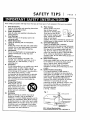
SAFETY TIPS I PAGE3
These simple precautions will help ensure that you get many years of safe enjoyment
1.
2.
3.
Read Instructions
Read all of the safety and operating instructions
before operating the product.
Retain Instructions
Keep all safety and operating instructions for
future reference.
7.
Heed Warnings
Follow warnings on the product and in the
operating guide.
Follow Instructions
Follow all operating and use instructions.
CLeaning
Unplug this product from the wall outlet before
cleaning, Do not use Liquid cleaners or aerosol
cleaners. Use a damp cloth for cleaning.
Attachments
Do not use attachments not recommended by
product manufacturer as they may cause
hazards.
Water and Moisture
8.
Do not use this product near water--for
example, near a bathtub, wash bowl, sink, or
Laundrytub, in a wet basement, or near a
swimming pool
Accessories
4.
5.
6.
Do not place product on an unstable cart, stand,
tripod, bracket, or table. Product may fail,
causing serious injury to a child or adult, and
seriousdamage to the product.Use onlywitha
cart,stand,tripod,bracket,
or table
recommended by the manufactureror soldwith
the product.Any mounting of productshould
follow manufacturers instructions and should
use a mounting accessory recommended by
manufacturer.
9.
10.
Transporting Product
Move productand cart
combinationswith care.Quick
stops,excessive
force,and
uneven surfacesmay cause
product and cart combination
to overturn.
VenUlation
Slotsand openingsin cabinetmust not be
blockedor covered.They are providedfor
ventilation,
to ensurereliable
operation,
and to
protectfrom overheating.
Never blockopenings
by placingproducton a bed, sofa,rug,or other
similar
surface.
Do not placeproductin built-in
installation
such as a bookcaseor rackunless
properventilation
isprovidedor manufacturers
instructions
have been adheredto.
from your new product.
11. Power Sources
Operate product only from
type of power source
indicatedon markinglabel.
Ifyou arenot sureofthe
type of power supplyto your
home, consultyour product
dealeror Localpower
company. For products intended to operate from
battery power or other sources, refer to manual
12. Une-Cerd Polarization
13.
Product is equipped with a polarized
alternating-current
line plug (a plug having one
blade wider than the other). As a safety feature,
this plug will fit into power outlet only one
way. If you're unable to insert plug fully into
outlet, try reversing the plug. If plug still fails
to fit, contact an electrician to replace your
obsolete outlet. Do not defeat safety purpose of
polarized plug.
Power-Cord Protection
Route power-supply cords so they are not likely
to be walked on or pinched by items placed
upon or against them, paying particular
attention to cords at plugs, convenience
receptacles, and the point where they exit from
product.
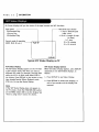
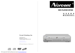
14. Outdoor Antenna Grounding
Ifan outsideantennaor cablesystem is
connectedto thisproduct,be sureantenna or
cab[esystemis groundedso as to providesome
protection
againstvoltagesurgesand built-up
staticcharges.Article
810 of the National
Electrical
Code (USA),ANSI/NFPA 70 provides
informationon groundingof mast and
supportingstructure,
groundingof lead-inwire
to an antenna dischargeunitconnectionto
groundingelectrodes,
and requirements
for
groundinge[ectrode.
( See Fig. 1 below. )
Fig. 1
AntennaLead-inWire
•
GlOtH)d
GroundingConducto_
N[C Section
B10-21
GrOundCl_rnps
=
ElectrodeSysteGrm
°unding
NEC Art 2_0,
Pall H
NEC: National Electrical Code
Antennagrounding per NECCode, ANSI/NFPA70
PAGE
4 I SAFETY TIPS
These simple precautions wilt help ensure that you get many years of safe enjoyment from your new product.
15. Lightning
For addedprotection
for this productduring
a l.lghtning storm, or
when product is l.eft
unattended and
unused for tong
periods of time,
unplug it from the
watt outlet and disconnect antenna or cable
system. This wilt prevent damageto product due
to l.ightning and power Line surges.
16. Power Lines
An outsideantennasystem shouldnot be
locatedin the vicinity of overheadpowertines
or other electriclight or powercircuits, or where
it can fat[ into such powertines
or circuits.
Wheninstallingan outsideantennasystem,take
extreme careto keep from touching suchpower
lines or circuits,as contact with them might be
fatal..
17. Overloading
Do notoverload
wattoutlets,
extension
cordsor
integral
convenience
receptacles,
asthiscan
result
inrisk
offire
orelectric
shock.
21. Replacement Parts
When replacementpart(s)arerequired,
be sure
servicetechnician
has used replacementpart(s)
specified
by manufactureror have same
characteristics
as original,
part(s).
Unauthorized
substitutions
may resultin fire,
electric
shock,
or otherhazards.
22.
Damage Requiring Service
Unplug this product from the watt out!.et and
refer servicing to qualified service personnel
under these conditions:
a. If power-suppLy cord or plug is damaged.
b. IfLiquidhas been spilledor objectshave
Fattenintoproduct.
c. Ifproducthas been exposed to rainor water.
d. Ifproductdoesn'toperatenormallyby
followinghandbook instructions.
Adjustonly
thosecontrolscoveredby handbook
instructions;
improperadjustmentof other
controls may resul.t in damage and often
requires extensive work by a qualified
technician to restore product to normal.
operation.
e. Ifproducthas been droppedor cabinethas
been damaged.
f. Ifproductexhibits
a distinct
change in
performance.
Heat
18. Object and Uquid Entry
Neverpushobjectsof any kind into this product
through openings,as they maytouch dangerous 23.
vol.tagepoints or short-out partsthat could
Keep product away
resultin fire or electricshock.Never spill ).iquid
from heat sources
such as radiators,
of any kindon product.
19. Servidng
heat registers,
Do notattemptto service
thisproduct
yourself,
stoves, or other
asopeningorremovingcoversmay exposeyou
products (including
todangerous
vo[tage
orotherhazards.
Refera[[
'amplifiers) that
servicing
to qualified
service
personnel.
produce heat.
20. Walt or Ceiling Mounting
Mount productto wall or ceiling only as
24. Safety Check
recommended
by manufacturer.
1l_)u_
Upon completionof any service
or repairsto
this product,ask service technician to perform
safety checksto determinethat productis in
properoperatingcondition,
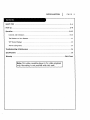
INSTALLATION
I
PAGE
5
SAFETYTIPS ......................................................
2-4
Hook-up .........................................................
6-8
Operation .......................................................
g-13
Contro|s and Indicators ............................................
9-10
The Buttons on Your Remote ..........................................
11
VCPStatus Displays ...............................................
12
How to using menu .................................................
13
TroubleshooUng & Maintenance
SpecificaUons
.........................................
.....................................................
Warranty ...................................................
Note: This video cassette player is for video playback
only. Recording is not possible with this unit.
14
15
Back Cover
PAGE
6
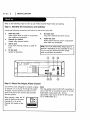
I INSTALLATION
Referto the for[owingstepsto hook up your Video CassettePLayereasi[yand quick[y.
Step 1: Identify
the Connectors and Switches
Locate the foLLowing connectors and switch on the back of your VCP;
1.
Video Out Jack
o
Video output must be used in conjunction
with audio out connection.
2.
3.
.
Channe| 3/4 Switch
Output video channel switch.
6.
DC Input .lack
Input from optiona|DC power source.
Audio Out Jack
Audio outputmust be used in conjunction
with video out connection.
Ant In Jack
Input from external antenna or cabLe-iv
Line.
Note: Use of the Audio/VideoOutputjacksis
RF Out Jack
optionaL.
Dependingon the capability
of your
TV,you may getimproved picturequality
Output to television.
when usingtheseconnections.
U
U DB
]
©
m
()
Step
2: Setect the Output
Video Channel
Your VCP has been designed to transmit a signa|
Note:
to channe[ 3 or 4 of your TV, TO get the proper
TV signaL, set the Channe[ 3/4 switch on the
back of the VCP to the channel that provides
the best picture.
Thisonly applieswhen the RF OUT connectionis
When playinga tape,the TV
must be tuned to the same
channe[ (3 or 4) as the
Channe[ 3/4 switchon the
VCP.
[M
used.Ifthe VCP isconnectedto your IV viathe
Audio/Videooutputjacksalso,choose
appropriate
inputsourceat the IV,(TV Channel
3/4 or AuBioiVideoIn.)
INSTALLATION
I
PAGE
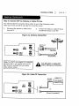
Step 3: Connect VCP to Antenna or Cabte-TV Line
Your antenna/cable-TV connection wi_ be similar to one of the i_ustrations
Match yours to the one like it and make the connections shown.
I.
Disconnect the antenna or cab[e-TV line
from the TV.
2.
below.
Connect the antenna or cabte-TV line to
the ANT IN terminal on the VCP.
Figure 2a: Antenna Connection
m
-//tl/
ii/'ii
J
Adapter
m
Flat Wire
300/75 ohm
_12V
or)
Round Wire
Note: The 300/75 ohm adapterisan optional
accessorythatisnot suppliedwith the VCP
Turn
offmaking
power any
or unptug
VCP
before
connections.
but shouldbe avai{able
from your Zenith
videoproductretailer.
Figure 2b: Cabte-TV Connection
CABLE-TV
CH 3/4
,_
DECODER/
CONVERTER
or
(Direct Connection)
7
PAGE
8
I INSTALLATION
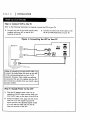
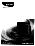
Step 4: Connect VCP to the TV
Refer to the following
1.
illustration
to properly connect the VCPto your TV.
Connect one end of the round coaxial cable
supplied with your VCP to the RF OUT
terrnina[ of the VCP;
Figure 3: Connecting
2.
Connect the other end of the cable to the
RF IN (or ANT IN)terminal on your 1_/.
the VCP to Your TV
I
(Back of TV)
VIDEO
IN
AUDIO
VHF/UHF/CATV
IN
Note: An alterative to using the RF cable is to
connect the Audio/Video Out jacks on the VCP
to the corresponding jacks on your TV (if
present). However, these cables are optional
accessories that are not supplied with the VCP
but should be avai|ab[e from your Zenith video
product retailer.
Step 5: Supply Power to the VCP
Plug the AC adapter power cord into an
operating 120V AC outlet and the other end
lo
into the DC input on the back of the VCP, or
t
Using the adapter cord, plug one end of the
cord into a 12 volt negative ground DC
source (such as the cigarette lighter socket
of a car) and the other end into the DC
input on the back of the VCP.
Y
OPERATION
I
PAGE
Descriptions of items you need to know to operate your VCP.
Controls and Indicators
1o
2.
3.
4.
POWER
Turns the VCPon or off.
TV/VCR Indicator
TV/VCR indicator is righted: To monitor,
view playback.
TV/VCR indicator is not righted: To view
channe[s selected by the TV tuner during
dubbing.
STOP/EJECT
Stops playback, fast forward, reverse,
rewind, or speed search. Cancels automatic
modes of operation.
Ejects a cassette from the Video cassette
compartment. If pressed while the VCP is
turned off, the power wi[[ turn on, the
cassette will be ejected, then the power
wiff turn off automaUca[[y.
DEW Indicator
Indicates excessive moisture condensation
is in the unit. Keep power on at room
temperature unti[ indicator turns off. The
VCPwi|[ not operate if the DEWindicator is
STILL
on.
Press during tape playback to pause the
tape and "freeze" the picture. Press PLAYto
resume normal playback. If left in the Stiff
mode for five minutes, the VCP wi[[
automaticaffy go into Stop mode to protect
the tape and the VCP from possib[e damage.
CST.IN (Cassette In) Indicator
Indicates a cassette is in the VCP.
A. (Auto) REPEATIndicator
Indicates automatic repeat is active.
o
Receives infrared rays from remote control
unit:,_
_-,
POWER Indicator
Indicates that the power is on.
REW (Rewind) Indicator
Indicates the VCPis rewinding.
PLAY Indicator
Indicates tape is playing.
FF (Fast Forward) Indicator
Indicates tape is fast forwarding.
REMOTESENSOR WINDOW
o
A. (Auto) REPEAT
Enables auto repeat. Tape will automatically
rewind when it reaches the end, then begin
to play again. Press a second time to
disab[e repeat.
(continued on next page)
g
PAGE
7.
10
I OPERATION
REW (Rewlnd/Reverse Search) Button
Press white the VCP is in Stop mode to
rewind the tape (no picture, no sound).
During tape ptayback, press to begin
Reverse Search; The picture portion of the
tape is played in the reverse direction at
high speed (sound is muted). PressSTOPto
end rewind or search.
Press and hold white Rewind mode to begin
Logic search, you can check what is on the
tape. When released, rewinding resumes.
8.
FF (Fast Forward/Forward Search)
Presswhite the VCPis in the Stop mode to
fastforwardthe tape (no pictureor sound).
Duringtape playback,pressto begin
Forwardsearch;The pictureportionof the
tape isplayedat high speed (thesound is
muted).PressSTOP to end Fastforwardor
search.
Pressand hold whiteFastforwardmode to
g. PLAY
Beginstape p|ayback.The correctplayback
speed isautomaticat[y
selected.
10.CassetteLoading Compartment
Inserta VHS videocassetteintothe video
cassettecompartment untititis
automaticaLLy
drawn intothe VCP.The
cassettecan be insertedeven when power
isoff.Power turnson automatically
and
ptaybackbegins.
CAUTION: DO NOT attemptto inserta
cassetteintothe compartmentwhen the
power cord isunptugged.
CAUTION" DO NOT insertfingers
intothe
cassettecompartment.
begin [ogicsearch,you can check what is
on the tape.When released,
Fastforwarding
resumes.
Playinga Video Cassette
• Turn on the IV.
• Ifthe VCP isconnectedto the IV viathe RF
OUT jack,tune the TV to the same channel
(3 or 4) as the Channet 3/4 switchon the
back of the VCP.
• Ifthe connectionin mode viathe VCP's
Audio/VideoOut jacks,your IV must be set
to receive audio and video from an auxitiary
source. (Refer to your TV operating
instructions.)
Normat TV Viewing
To watch TV,simplyplaceVCP in TV mode by
pressingTV/VCR on the remote repeatedly
until
the TV/VCR indicator
tightdisappearsfrom the
VCP frontpaneL.Ifthe IV antenna or cabte-TV
finehas been connectedto the VCP as shown
in thismanual,itssignalwiLLpassthroughthe
turned-off
VCP unaffected,
as ifconnected
directly to the IV.
• To view a VHS cassettetape,insertitintothe
cassettecompartment.The VCP wit[
automaticat[y
turnon, p[aythetape to its
end, rewindthe tape,ejectthe tape,and shut
off.Ifnecessary,
use the TRK (TRACKING)
control
to adjustforthe bestpicture.
OPERATION
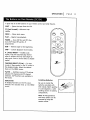
A quick List of aLLthe buttons on your remote control and what they do.
F-,1ECT
--
Ejects the tape from the VCP,
FF (Fast Forward)--Advances tape
rapidly.
power
_A
C:)
MENU -- Shows main menu.
PLAY -- Beginstape playback.
POWER -- Turns VCP On and Off. A[so
turns VCP Timer Off and On, if
programmed.
REW --
Rewinds tape to the beginning.
a,rBpeat
c:)
Iv/wr
STOP -- CanceLsplayback record modes.
A. (Auto) REPEAT-- EnabLesauto
repeat. Tape wilt automaticat[y rewind
when it reaches the end, then begin to
play again. Press a second time to disable
repeat.
TRACKING/SELECT (V/A)
-- To clear
streaks if they appear on the TV screen in
the p[ayback mode. Se[ect the desired
items on the MENU screen.
TV/VCR -- Switches source of TV picture
between TV channel and VCP channel
selection. VCP functions are available in
VCR mode.
DISPLAY/OK
To displayfunctionson the TV screen.
Switchesthe selecteditem on the MENU
screen.
InstaLLing Batteries
Be sure to instaLL the
batterie s provided with
this remote. Match positive
(+) and negative (-) with
markings shown in battery
compartment.
Note: AllVCP,operations
and menu optionscan be
accessedby usingthe
remotecontrol.
m_nu
c::)
I
PAGE
11
PAGE
12
I OPERATION
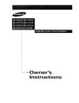
On-Screen displays tell you the status of the tape inserted and VCP functions.
Tape Speed
EP=Extended Play
--
- = Tape is rewound past
index mark.
LP=Long Play
SP=StandardP_y
-1:35:45 = Length of tape
(in time)
1 = I hour
35 = 35 minutes
Current mode of operation
(STOP, PLAY, FF,etc.)
ReaL-time tape counter
-PLAYSP
45 = 45 seconds
L
-1:35:45
Typical VCP Status Display on TV
VCP Status Disp[ay
The VCP Status DispLayappears on the TV when
a VCPfunction starts, like when you select a
different VCP mode. For example, pressing STOP
while the VCP is in PLAY mode shows STOPin
the display. Press DISPLAYon the remote at any
time (except Special Effects Playback mode;
STILL etc.) to see the Status Display.
Note:
If the VCPStatus DispLaydoes not appear on
the TV screen, check the FUNCTIONOSDoption
on the MENU. SeLect ON to see the display. See
"How to using menu" section for details.
VCP Status DispLay Options
When the StatusDisplayappears,pressDISPLAY
repeatedly
to see abbreviateddisplays,
as
foLLows:
1. PressDISPLAYto see StatusDispLay.
2. Press DISPLAYto remove the displays, or
wait a few seconds and the displays are
removed.
OPERATION
I
MENU
IAUTOREPEAT
EOSD
SELECT:VA.,
OK
OFFI
ON
END:MENU
How to Access Menu
1 Press MENU to see menu.
2
Pressthe SELECT (V/A) to choose desired
optionto be changed.Then you setdesired
mode by pressingthe OK button
repeatedly.
Press MENU to exit menu, or wait a few
minutes and the VCP returns to normal
operation.
AUTO REPEAT
Ifyou want to playback tape repeatedly,
set
AUTO REPEAT optionto ON.
• When the end of the tape is reached,the
unitautomatically
rewindsthe tape to the
beginningand repeatsplayback
continuously.
• Ifyou releasethisfunction,
setthe AUTO
REPEAT to OFF mode.
F.(Function) OSD
Switches the on-screen display ON or OFF.
Note:
Performmenu operationswiththe VCP and TV
on, and tune the iV to channel3 or 4. The VCP
must alsobe in the VCR mode of operation.
Pressthe TV/VCR button on the Remote Control
untilTV/VCR indicator
lightappearsin the
frontpanel.
Point remote toward VCP
I
PAGE
13
PAGE
14
I TROUBLESHOOTING
AND
MAINTENANCE
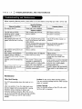
Before requesting Warranty service, please refer to the chart below. It may help you avoid a service caLL.
Operating Problems
Observed Condition
No power to the VCP.
PossibLeCause
Powercord is not connected.
Probable So[ution
Connect it.
PLayback Problems
The tape wiLLnot rewinds
Tape is already fully rewound.
No action is necessary.
Operating sound is audible
during playback, rewind, fast
Forward. etc.
Normal condition.
No action is necessary.
The playback picture does not
appear while the tape is running.
You are using the RFOUT jack but
the TV is not turned to the correct
video channel..
Set the IV to either channel 3 or
channel 4.
You are using the VCPaudio/video
Out jacks but the TV is not set to
AUX channel or Audio/video In
source,
Set the IV to AUXchannelor
Audio/VideoIn source.
Noise appears during search and
stiff pictures.
Normal condition.
No action is necessary.
Noise appears during playback.
The tracking needs to be adjusted.
AdJusttracking.
Playback picture is blurred or
interrupted while normal IV picture
is dear.
Video heads may be dirty.
Head cleaning is necessary.
ConsuLtyour LocalZenith video
retailer.
[assette cannot be inserted into
The cassette is being Loaded
backwardsor upside down or
another cassette is already loaded.
Load cassette in direction Indicated
by arrow on cassette, or remove the
cassette that is Loadedalready.
VCP.
Power cord is not connected.
Connect power cord.
Remote control does not work.
Batteries are not installed or oLd.
Install or replace with new batteries.
DEWIndicator is [it.
Excessive condensation.
Keep power on until indicator turns
off.
Maintenance
Video Head CLeaning
Your VCPautomaticaLLy cleans the heads as it is
used.
After Longpenods of use, the video heads may
become clogged with accumulated dirt, causing
distortion (snow, streaking in picture and
horizontal pulling of picture). When this occurs,
use do-it-yourseLf VHS wet head cleaning cassettes
avaffabLe through your Zenith video product
retailer.
Caution: Do not use dry head cleaning systems.
They may seriously damage both the video cassette
player an cassette.
Cabinet Cleaning
Clean the _)utside surfaces of the VCPwith a soft,
lint-free cloth as required.
SPECIFICATIONS
I
PAGE
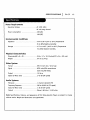
Power Requirements
Operating Vottage ................
AC 120V, 60Hz
DC 12V, Neg. Ground
Power consumption
...............
11W (AC)
11W (DC)
Environmental CondiUons
Operation
.....................
41°F to 95°F (5°C to 35°C) Temperature
35 to 80% Relative Humidity
Storage .......................
-4°F to 140°F (-20°C to 60°C) Temperature
5 to 80% Retative Humidity
Physica| Characteristics
Dimensions(W x H x D) .............
10.6 x 3.7 x 12.8 Inches(270 x 94 x 325 ram)
Weight
6.4 tbs (2.9 kg)
.......................
Video System
Format .......................
VHS 1/2 Inch (12.7 rnm) Tape
Signal ........................
NTSCcotor/EIA monochrome
(525 tines/60 fietds)
Output
.......................
Signal-to-Noise
Audio
ratio
1.0 Vp-p
..............
> 43 dB (SP speed)
Systems
Monaural ......................
1 channet standard VHS
Frequency Response ...............
200 to 8,000 Hz (SP speed)
Signal-to-Noise
_>38 dB (SP speed)
Output
ratio
.......................
Note: Specifications,
without
..............
Minus 6 d8 into < 1,500 ohms
features, and appearance of this Video,Cassette Prayer are subject to change
notice. Weight and dimensions are approximate.
15
VIDEO CASSETTERECORDEROR PLAYER
Welcome into the Zenith family! We beUeve that you wiU be pleased with your new Zenith Entertainment Machine. Please read this
warranty carefully, it is a "LIMITED WARRANTY"as defined under Federal Law. This warranty gives you specific Legal rights,
and you may also have other fights that vary from state to state within
the U.S.A.
ZENITH'S RESPONSIBILITY
ServiceLabor
Duringa periodof 90 days from effective
warrantydate,Zenithwillprovideservicelaborby a Zenith
authorizedservicecenter
when needed as determinedby Zenith,as a resultof manufacturingdefects.
Parts
New or remanufactured repbcements for factory-defective
parts wit[ be supplied by a Zenith authorized
se_ice center for one year from effective warranty date. Such replacement parts are warranted for the
remaining portion of the original warranty period.
Not Covered
Thiswarrantycoversmanufacturingdefectsand does not coverinstallation,
adjustmentof customer
controls
in the home, installation
or repairof home antenna systems,cableconverters
or cablecompanysuppliedequipment;itaLsodoes not coverdamage due to misuse,abuse,negligence,
actsofGod or other
causes beyond the controlofZenith.Any alteration
ofthe productaftermanufacturevoidsthiswarranty
in itsentirety.
OWNER'S RESPONSIBILITY
Effective Warranty Date
Warranty begins on the date of original consumer purchase. For your convenience, keep the dealer's dated
bit[ of sale or a de|ivery ticket as evidence of the purchase date.
Operating Guide
Read your OperatingGuide carefully
so thatyou wiLLunderstandthe operationofyour set and how to
adjustthe customercontrols.
Carry-In Service
The videoproductmust be taken to a U.S.or CanadianZenithauthorizedservicecenterforwarranty
serviceand must be pickedup by the owner.
TV Set Performance
Important
It is the owner's responsibiUty to maintain the TV receiver with which the video product is used, and the
associated antenna system, in proper operating condition.
ProductRegistration--Please
flU.
out and mailyour ProductRegistration
Card.ItisimperativethatZenith
know how to reachyou promptlyifwe should discover
a safetyproblemthatcouldaffectyou.
Warranty Service
Forwarrantyserviceinformation,
contactany Zenithauthorizedservicecenter.Partsand servicelaborthat
areZenith's
responslbility
(seeabove) willbe providedwithoutcharge.Otherserviceisatthe owner's
expense.Ifyou have any problemin obtainingsatisfactory
warrantyservice,
cai[or writethe Zenith
ResponseCenter.You must providethe mode[ number,serialnumber and date ofpurchaseordate of
origina[
installation.
Beforeyou ask forwarrantyservice,
read"MaintenanceAnd Troubleshooting"
inyour
operatingguide.You might avoid a servicecall
THIS WARRANTY IS IN LIEU OF ANY OTHER WARRANTY, EXPRESS OR IMPLIED,INCLUDING WITHOUT LIMITATION,ANY WARRANTY OF
MERCHANTABILITY OR FITNESSFOR A PARTICULAR PURPOSE, AND ZENITH SHALL NOT BE LIABLE FOR ANY CONSEQUENTIAL, INDIRECT,
OR INCIDENTAL DAMAGES OF ANY KIND, INCLUDING LOST REVENUES OR PROFITSIN CONNECTION WITH THE PRODUCT.
Customer
Service
Zenith National
Response
Center
201 James Record Road, Building
#3
Huntsville,
AL 35824
Phone: (256) 772-1515
Fax: (256) 774-4070
emaih
[email protected]
ZENITH ELECTRONICS
CORPORATION
1000 MILWAUKEE AVENUE
GLENVIEW, ILLINOIS 60025-2493
Zenith Part No. 206-3520
GS# 3835RM0035C
Printed in Korea
Issue O