1
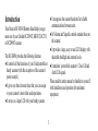
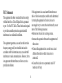
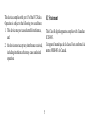
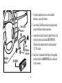
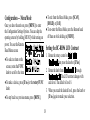
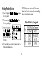
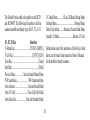
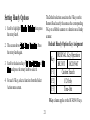
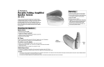
Table of Contents
Introduction...................................................................................................... 3
FCC Statement........................................................................................... 4
IC Statement.............................................................................................. 5
Mounting the BC-RH96.................................................................................. 7
Using the Mounting Bracket...................................................................... 7
Using Hook and Loop Material................................................................. 9
BC-RH96 Connections.................................................................................. 10
Connecting Cables......................................................................................... 11
Remote Head and Scanner Power............................................................ 11
Control Cable........................................................................................... 11
Data Port Cable — Firmware Updates.................................................... 12
Control Configuration Guides...................................................................... 13
The BR330T Key Configuration.............................................................. 14
The BCD396T Key Configuration........................................................... 14
The BCT15 Key Configuration................................................................ 15
The BCD996T Key Configuration........................................................... 15
Operation........................................................................................................ 16
Setting the BC-RH96 Backlight.............................................................. 17
Configuration — Menu Mode.................................................................. 18
Setting the BC-RH96 LCD Contrast....................................................... 18
Setting Mobile Options.................................................................................. 19
Mobile Default Key Assigment............................................................... 19
Setting Handy Options.................................................................................. 21
Default Handy Option Key Assigment.................................................... 21
Setting the Function Mode............................................................................ 22
Setting Hold Timer................................................................................... 22
Setting Auto Release................................................................................ 23
Miscellaneous.................................................................................................. 23
Volume Settings - For Handy Scanner..................................................... 23
Control Limitations.................................................................................. 24
Serial Operation Precautions................................................................... 24
Initialize Memory (Reset)........................................................................ 25
Using the Cable Clamp............................................................................ 25
Specifications.................................................................................................. 26
One Year Limited Warranty......................................................................... 26
© 2007 Uniden America Corporation, Fort Worth, TX 76155 All Rights Reserved
● It recognizes the scanner baud rate for reliable
communications between units.
● Its Volume and Squelch controls emulate those on
the scanner.
● It provides a large, easy to read LCD display with
adjustable backligh and contrast levels.
● It emulates your mobile scanner’s Close Call and
Alert LED signals.
Please read the entire manual to familiarize yourself
with installation and operation for maximum
enjoyment.
Introduction
Your Bearcat BC-RH96 Remote Head helps you get
more out of your Uniden BCD396T, BR330T, BCT15,
or BCD996T scanner.
The BC-RH96 provides the following features:
● It controls all the functions of your Uniden mobile or
handy scanner (with the exception of the scanner’s
power control.)
● It gives you three shortcut keys that you can assign
to your scanner’s most often used operations.
● It serves as a large LCD with your handy scanner.
FCC Statement
If this equipment does cause harmful interference to
radio or television reception, which can be determined
by turning the equipment off and on, the user is
encouraged to try to correct the interference by one or
more of the following measures:
● Reorient or relocate the receiving antenna.
● Increase the separation between the equipment and
the receiver.
● Connect the equipment into an outlet on a circuit
different from that to which the receiver is
connected.
● Consult the dealer or an experienced radio/TV
technician for help.
This equipment has been tested and found to comply
with the limits for a Class B digital device, pursuant
to part 15 of the FCC Rules. These limits are designed
to provide reasonable protection against harmful
interference in a residential installation.
This equipment generates, uses and can radiate radio
frequency energy and, if not installed and used in
accordance with the instructions, may cause harmful
interference to radio communications. However, there
is no guarantee that interference will not occur in a
particular installation.
IC Statement
This device complies with part 15 of the FCC Rules.
Operation is subject to the following two conditions:
1. This device may not cause harmful interference,
and
This Class B digital apparatus complies with Canadian
ICES-003.
Cet appareil numérique de la classe B est conforme à la
norme NMB-003 du Canada.
. this device must accept any interference received,
including interference that may cause undesired
operation.
● Remote connection cable, 10 feet in length.
● A correctly polarized vehicle DC adapter to let you
connect the Remote Head to a convenience outlet in
your vehicle that provides 12-13.8 VDC.
● This Owner’s Manual.
● A set of pocket-sized Quick Reference Configuration
cards for convenient setup and usage.
● A Self Adhesive Cable Clamp
Included with your BC-RH96
Your Bearcat Remote Head is supplied with essential
components and accessories to get you operational.
Supplied are:
● The BC-RH96 Remote Head unit.
● A steel mounting bracket with attachment washers factory installed.
● Mounting hardware (screws and washers)
to attach the bracket.
● Threaded knobs to allow mounting the Remote Head quickly to the bracket.
If any of the above items are missing or damaged,
immediately contact your place of purchase or Uniden
Customer Service at (800) 297-1023.
Mounting the BC-RH96
or in front of your dash, armrest console, or other
location. If you drill carelessly, expensive damage can
result. If in doubt, consult your vehicle dealer’s service
department or a qualified professional installer.
The following two mounting methods are suggestions
used by most. Depending upon your individual
situation, you may decide on a different approach.
Important: AVOID AIRBAG DEPLOYMENT
ZONES. Ignoring this installation concern may result
in bodily harm and the inability of the airbag to perform properly.
Be sure to select a mounting location so that when you
route power and remote cables they do not interfere
with any existing cables or other controls.
Check local laws to determine if using a scanner is
legal in your area.
Using the Mounting Bracket
For most vehicles, the supplied bracket will be the
easiest method of mounting.
With the bracket removed from the Remote Head, use
the holes in the bracket as a template to initially mark
the location you plan to use in your vehicle. Be absolutely certain of what might be behind the mounting
surface before making any holes, be it above, or below,
●-
1. Using the supplied screws or other suitable
hardware, secure the bracket.
. Insert the BC-RH96 and insert the bracket knobs
to lock the Remote Head in position.
Under Dash
Bracket
3. Attach the provided Cigarette Lighter Power Cord
to the rear power jack marked DC IN 13.8V.
Then plug the adapter end into a dash mounted
12V DC socket.
Star
Washers
& Screws
Bracket
Knobs
4. Insert the 3-Conductor Mini-Plug of the supplied
ten-foot cable in the REMOTE jack on the back
of the scanner.
BC-RH96
5. Route the Remote Cable through the Slotted Guide
(3) so it lies flat. Route the Power Cord so it does
not interfere with any other wires.
Follow the directions supplied with the hook and loop
material. Locate a suitable spot on the dash, console,
or other area. If you use the Remote Head in another
place such as a radio room, using tape lets you quickly
mount or remove the Head as desired.
Using Hook and Loop Material
The rear of the unit, when all connectors and cables
are properly routed, is flat. This permits using hook
and loop material (not supplied) that has a heavy-duty
peel and stick adhesive on one side. This material is
generally available from electronic supply stores and
hardware stores.
Do not apply the tape to the rear until all cables are
installed and routed correctly.
Do not cover the slotted guide with the tape.
Note: The two slots on the front of the Remote Head
cannot be used for mounting. These slots are cosmetic
features only.
BC-RH96 Connections
Note: Connect the Remote Cable and route it through the cable channel as
shown. Then connect the DC Power Cable and route it through the channel.
1
DC IN 13.8V
REMOTE
2
Always route both cables
through the channel.
3
1
DC Power Input Jack
2
To Remote Cable
Mini-Plug
3
Cable Routing Guides
4
Data Port (for firmware updates)
4
10
Connecting Cables
diameter and wire it with the center positive using at
least 18 gauge wire to an extra fuse block terminal of
your vehicle.
There are three cables that you can connect to the BCRH96.
● The DC power cable
● The Remote Control cable
● The Data Port cable (not supplied with BC-RH96)
The Remote Head cannot turn power to the scanner
off or on. Therefore, consider connecting the power
lead of the scanner to a terminal on your vehicle that is
turned off when you turn off the ignition key.
Remote Head and Scanner Power
To provide power to the Remote Head, insert the barrel
of the cigarette lighter adapter into the jack in the back
of the unit marked DC IN 13.8V. Insert the other end
in a convenient socket on the dash of your vehicle.
To connect a power lead permanently, obtain a barrel
connector 5.5 mm diameter, with a center pin 2 mm
Control Cable
The ten-foot supplied Control Cable has a stereo miniplug on one end and a scanner serial connector on the
other. Insert the mini-plug into the REMOTE jack on
the rear of the Remote Head. Route the cable through
11
the guides to keep the cable correctly positioned. Then,
route the remainder of the cable toward the location of
your target scanner. When doing so, be sure to avoid
sharp metal edges of your vehicle’s body, or other
possible hazards. Be sure the cable does not interfere
with controls, operation of the vehicle, or passenger
safety. Insert the cable’s special connector in the front
port of the BCT15/BCD996T mobile scanner, or the
side port of the BR330T/BCD396T handy scanner.
nect the data transfer cable to this port on the bottom
of the Remote Head. Connect the other end to the DB9
serial port on your PC. This is the only purpose of this
connection.
Important:
For best operation, be sure your scanner always has the
latest firmware. Visit www.uniden.com to verify that
your scanner has the most up-to-date firmware.
Data Port Cable — Firmware Updates
The Remote Head has a data port (see BC-RH96
Connections)so you can update the firmware using the
data transfer cable provided with your scanner. Con12
Control Configuration Guides
Important: If you have more than one scanner, be sure
to turn off power to the BC-RH96 before switching
target scanners.
The BC-RH96 lets you remotely operate the following
scanners:
● BCT15 Mobile Scanner
● BCD996T Mobile Scanner
● BR330T Handy Scanner
● BCD396T Handy Scanner
To assist you to better understand each of these
changes, a set of pocket-sized Quick Reference Cards
are provided. The diagrams on the next pages replicate
the card diagrams.
Even though the scanners have different controls and
functions, when you connect the BC-RH96 to the
scanner, the Remote Head automatically changes the
functionality of its controls to match the operation of
the target scanner.
13
FUNC
BR330T
F1
F2
pri
FUNC
wx
LIGHT
F1=
L/O
F1
F2
pri
wx
F3
F3
MENU
BCD396T
rcl
race
rev car
F2=
MENU
L/O
att
LIGHT
F1=
F3=
The BR330T Key Configuration
rcl
rev
F2=
att
F3=
The BCD396T Key Configuration
14
BCT15
STATE
F1
F2
F3
MENU
BCD996T
F1
PRI WX
F2
SRCH1 SRCH2 SRCH3
FUNC
F3
ATT REV ALERT
MENU
L/O
SRCH4 SRCH5 SRCH6
FUNC
ATT REV
L/O
LIGHT
MUTE
F + LIGHT
F1=
SRCH1 SRCH2 SRCH3
F2=
F1=
F3=
The BCT15 Key Configuration
F2=
F3=
The BCD996T Key Configuration
15
Operation
If you have not connected a target scanner, you see
the screen below. If the BC-RH96 remains on while
you turn on the scanner, this display is automatically
replaced with the scanner’s initial display.
Apply power to your target scanner and set its Baud
Rate to the highest setting. Make sure that the Remote
Control cable is properly connected, and rotate the
VOL control clockwise past OFF until it clicks.
$%4*
The LCD displays the following screens (your version
number may be different than the screen shown here):
$%4*
2TGUU/'07-G[
HQT%QPHKI
5ECPPGT
7PEQPPGEVGF
7PKFGP$GCTECV
$%4*
8GTUKQP
16
When you turn the Remote
Head off, you see the screen
to the right which reminds
you that power is still
applied to the target scanner.
Brightness Auto-Adjust (mobile scanners only)
When you connect a mobile scanner, the Remote Head
automatically adjusts its backlight brightness level to
match the brightness level of the target mobile scanner.
If you change the brightness level on either the Remote
Head or the target scanner, the level changes on
both devices at the same time. (This function is not
available on Handy Scanners.)
2QYGTKPIFQYP
VJGTGOQVGJGCF
FQGUPQVVWTP
QHHVJG5ECPPGT
Setting the BC-RH96 Backlight
To adjust the backlight brightness level on the Remote
Head, repeatedly press the VOL control. The display
cycles through available backlight brightness levels,
including off. Stop when you reach the desired level.
Note: If the Remote Head is connected to a BCT15 scanner, press F + VOL control to change the
backlight brightness level.
17
Configuration — Menu Mode
● To exit from the Menu Mode, press [SCAN],
[HOLD], or [L/O].
● To re-enter the Menu Mode, turn the Remote head
off then on while holding in [MENU].
Once you have the units on, press [MENU] to enter
the Configuration Settings Options. You can skip the
opening screens by holding [MENU] while turning on
power. You see the Remote
4GOQVG*GCF/GPW
Head Menu screen.
● To select an item on the
screen, rotate the FUNC
knob to scroll to the item.
Setting the BC-RH96 LCD Contrast
5GV.%&%QPVTCUV
/QDKNG1RVKQP
*CPF[1RVKQP
1. Rotate the rotary control to Set LCD
Contrast then press the knob or [E/Yes].
. Rotate the knob from Contrast 1 through
Contrast 15. The LCD contrast changes with
each level. The default is level 8.
3. When you reach the desired level, press the knob or
[E/Yes] again to make your selection.
● To make a choice, press [E/Yes] or the rotary FUNC
knob.
● To step back to a previous menu, press [MENU].
18
Setting Mobile Options
The Default selection associates the F Keys on the
Remote Head exactly the same as the corresponding F
Key on the target mobile scanner.
1. Scroll to highlight Mobile Option, then press
the rotary knob.
. The screen shows Set Key Assign. Press
the rotary knob again.
Mobile Default Key Emulation
Mobile Default Key Assigment
3. Scroll to the desired
key (F1 Key, F2
Key, or F3 Key) and
press the rotary knob
to select it.
ORIGINAL Key Operation
BCD996T
BCT15
[F1]
[PRI]
[POL/DOT]
[F]
[WX]
[HP/BT]
[F3]
[GPS]
[GPS]
5GNGEV#EVKQP
&GHCWNV-G[
(/GPW-G[
(.1-G[
Key
4. For each F Key, you can select a function from the
Select Action menu screen.
19
The Default Option table only applies to the BCT15
and BCD996T. The following list applies to all four
scanners (mobile and handy type) for F1, F2, or F3.
CC Band Menu.............Close Call Band Setting Menu
Settings Menu........................................ Settings Menu
Brdcst Scrn Menu..........Broadcast Screen Band Menu
Search L/O Menu................................Review L/O List
F1, F2, F3 Key
Function
F+Menu Key....................................[FUNC]+[MENU]
F+L/O Key............................................[FUNC]+[L/O]
Scan Key............................................................. [Scan]
Hold Key.............................................................[Hold]
Service Menu................... Service Search Range Menu
WX Scan Menu............................WX Operation Menu
Goto Custom...............................Custom Search Mode
Goto CC Only........................... Close Call Only Mode
Goto Tone-Out....................... Tone Out Standby Mode
Details about each of the operations of the F keys listed
above can be found in the respective Owner’s Manual
for the mobile or handy scanners.
20
Setting Handy Options
The Default selection associates the F Keys on the
Remote Head exactly the same as the corresponding
F Key on a Mobile scanner or a function on a Handy
scanner.
1. Scroll to highlight Handy Option, then press
the rotary knob.
Handy Default Key Emulation
Default Handy Option Key Assigment
. The screen shows Set Key Assign . Press
the rotary knob again.
ORIGINAL Key Operation
BR330T
BCD396T
[F1]
Custom Search
[F]
CC Only
[F3]
Tone-Out
Key
3. Scroll to the desired key (F1 Key, F2 Key, or F3
Key) and press the rotary knob to select it.
4. For each F Key, select a function from the Select
Action menu screen.
F Key column applies to the BC-RH96 F keys.
21
The five settings are:
Off:
Function mode is continuously enabled only
while pressing the Control or SQ knob.
Setting the Function Mode
If you scroll to the Handy Option menu, you can
highlight Set Func Mode.
Select this to choose between Set Hold Timer
and Set Auto Release.
Setting Hold Timer
When you select this option, you can scroll through
and select from five settings. The setting determines
how long the knob acting as the FUNC control is
enabled each time you press it if you do nothing else.
3 sec:
Function mode is enabled for 3 seconds after
releasing the Control or SQ knob.
5 sec:
Function mode is enabled for 5 seconds after
releasing the Control or SQ knob.
10 sec: Function mode is enabled for 10 seconds after
releasing the Control or SQ knob.
Infinite:Function mode is enabled until the Control or
SQ knob is pressed again (default).
22
Setting Auto Release
Miscellaneous
Choose this option to set the Function Auto Release to
On or Off.
Volume Settings - For Handy Scanner
While it is possible to configure the BC-RH96 rotary
FUNC control as your VOL control, we suggest not
doing so. The VOL control still functions as a volume
control. If the FUNC control is configured as volume,
it is possible to have a situation that a very slight
movement of the VOL control results in a sudden and
loud increase in your audio. It is best to configure the
VOL control as volume in all cases.
Turning the Auto-Release on lets you press any key to
exit the Function mode.
Turning the Auto-Release off (the default setting)
means you can only press the Function key to exit
Function mode. No other key has any effect.
23
Control Limitations
Serial Operation Precautions
There are some operations that cannot be performed
using the BC-RH96.
The BCT15 and the BCD996T have a 9-pin serial
connection in the back designed for use with serial
operations in addition to the special serial jack on the
front.
Other than connecting a GPS, the front and the back
cannot be used or connected at the same time when the
BC-RH96 is in use.
For example, if you connect a 9-pin serial cable to
your PC to use the UASD programming software,
disconnect the BC-RH96 front cable first.
Operation
Power control
Wired and On-Air Clone
Upside Down Display
Backlight Scanner Control
Key Lock Operation
No Close Call & Alert LED
Scanner Type
All
All
Mobile
Handy
Handy
Handy
24
Initialize Memory (Reset)
Using the Cable Clamp
A self-adhesive clamp/
guide is provided to
assist you to safely
route the Remote Cable
to your target scanner.
With the unit off, press and hold the following keys
Clean the planned
and turn on power at the same time: [2], [9] and
location, peel the base
[HOLD].You see the reset screen below.
covering, and firmly
If you turn off power
press it on the scanner.
during reset, the process
Then route the Remote Cable through the guide. This
starts again when you next #NN/GOQT[%NGCT helps assure that the remote Cable will not come out
turn on the unit.
2NGCUG9CKV
of the special connector on either a Mobile of Handy
scanner.
To reset the BC-RH96 to factory default settings,
follow the sequence below. Note that once done, there
is no undo and all programmed keys are reset.
25
Specifications
Size (inches)
7.2 W x 1.9 D x 2.2 H
(without knobs)
Weight (Remote
Head only)
0.7 pounds
Input Voltage
13.8 Vdc (11.0 - 16.6 Vdc)
Current Drain
(nominal)
In standby: 2 mA
In use: 106 mA (backlight high)
Operating
Temperature
-20° to +60° C
(-4° to +140° F)
One Year Limited Warranty
Important: Evidence of original purchase is required for warranty
service. WARRANTOR: UNIDEN AMERICA CORPORATION
(“Uniden”) ELEMENTS OF WARRANTY: Uniden warrants, for one
year, to the original retail owner, this Uniden Product to be free from
defects in materials and craftsmanship with only the limitations or
exclusions set out below.
WARRANTY DURATION: This warranty to the original user
shall terminate and be of no further effect 12 months after the
date of original retail sale. The warranty is invalid if the Product
is (A) damaged or not maintained as reasonable or necessary,
(B) modified, altered, or used as part of any conversion kits,
subassemblies, or any configurations not sold by Uniden, (C)
improperly installed, (D) serviced or repaired by someone other
than an authorized Uniden service center for a defect or malfunction
covered by this warranty, (E) used in any conjunction with
26
equipment or parts or as part of any system not manufactured by
Uniden, or (F) installed or programmed by anyone other than as
detailed by the owner’s manual for this product.
STATEMENT OF REMEDY: In the event that the product does not
conform to this warranty at any time while this warranty is in effect,
warrantor will either, at its option, repair or replace the defective
unit and return it to you without charge for parts, service, or any
other cost (except shipping and handling) incurred by warrantor
or its representatives in connection with the performance of this
warranty. Warrantor, at its option, may replace the unit with a
new or refurbished unit. THE LIMITED WARRANTY SET FORTH
ABOVE IS THE SOLE AND ENTIRE WARRANTY PERTAINING
TO THE PRODUCT AND IS IN LIEU OF AND EXCLUDES ALL
OTHER WARRANTIES OF ANY NATURE WHATSOEVER,
WHETHER EXPRESS, IMPLIED OR ARISING BY OPERATION
OF LAW, INCLUDING, BUT NOT LIMITED TO ANY IMPLIED
WARRANTIES OF MERCHANTABILITY OR FITNESS FOR A
PARTICULAR PURPOSE. THIS WARRANTY DOES NOT COVER
OR PROVIDE FOR THE REIMBURSEMENT OR PAYMENT OF
INCIDENTAL OR CONSEQUENTIAL DAMAGES. Some states do
not allow this exclusion or limitation of incidental or consequential
damages so the above limitation or exclusion may not apply to you.
LEGAL REMEDIES: This warranty gives you specific legal rights, and
you may also have other rights which vary from state to state. This
warranty is void outside the United States of America and Canada.
PROCEDURE FOR OBTAINING PERFORMANCE OF WARRANTY:
If, after following the instructions in the owner’s manual you are certain
that the Product is defective, pack the Product carefully (preferably
in its original packaging). The Product should include all parts and
accessories originally packaged with the Product. Include evidence
of original purchase and a note describing the defect that has caused
you to return it. The Product should be shipped freight prepaid, by
traceable means, to warrantor at:
Uniden America Service
4700 Amon Carter Blvd.
Fort Worth, TX 76155
27