1
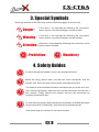
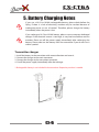
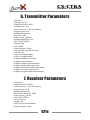
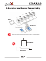
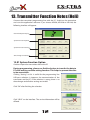
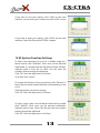
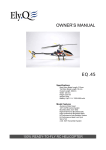
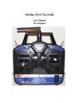
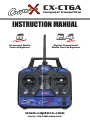
CX-CT6A
Computer Transmitter
INSTRUCTION MANUAL
6 channel Radio
Control System
Digital Propotional
Radio Control System
www.copterx.com
Copyright © 2008 KY MODEL Company Limited.
CX-CT6A
Computer Transmitter
MENU
Table of content . . . . . . . . . . . . . . . . . . . . . . . . . . . . . . . . . . . . . . . . . . . . . . . . . . . . . . . . . . . . . . . . . . . . . . . . .
1
1. Introduction . . . . . . . . . . . . . . . . . . . . . . . . . . . . . . . . . . . . . . . . . . . . . . . . . . . . . . . . . . . . . . . . . . . . . . . . . . . . . 2
2. Services . . . . . . . . . . . . . . . . . . . . . . . . . . . . . . . . . . . . . . . . . . . . . . . . . . . . . . . . . . . . . . . . . . . . . . . . . . . . . . . . . 2
3. Special Symbols . . . . . . . . . . . . . . . . . . . . . . . . . . . . . . . . . . . . . . . . . . . . . . . . . . . . . . . . . . . . . . . . . . . . . . . . 3
4. Safety Guides . . . . . . . . . . . . . . . . . . . . . . . . . . . . . . . . . . . . . . . . . . . . . . . . . . . . . . . . . . . . . . . . . . . . . . . . . . . 3
5. Battery Charging . . . . . . . . . . . . . . . . . . . . . . . . . . . . . . . . . . . . . . . . . . . . . . . . . . . . . . . . . . . . . . . . . . . . . . . . 4
6. Transmitter Parameters . . . . . . . . . . . . . . . . . . . . . . . . . . . . . . . . . . . . . . . . . . . . . . . . . . . . . . . . . . . . . . . .5
7. Receiver Parameters . . . . . . . . . . . . . . . . . . . . . . . . . . . . . . . . . . . . . . . . . . . . . . . . . . . . . . . . . . . . . . . . . . . 5
8. Respective Part of the Transmitter . . . . . . . . . . . . . . . . . . . . . . . . . . . . . . . . . . . . . . . . . . . . . . . . . . . . 6
9. Receiver and Server Connectivity . . . . . . . . . . . . . . . . . . . . . . . . . . . . . . . . . . . . . . . . . . . . . . . . . . . . . 7
10. 2.4G Operation Notes . . . . . . . . . . . . . . . . . . . . . . . . . . . . . . . . . . . . . . . . . . . . . . . . . . . . . . . . . . . . . . . . . . 8
10.01 Matching . . . . . . . . . . . . . . . . . . . . . . . . . . . . . . . . . . . . . . . . . . . . . . . . . . . . . . . . . . . . . . . . . . . . . . . . . 8
10.02 Boot . . . . . . . . . . . . . . . . . . . . . . . . . . . . . . . . . . . . . . . . . . . . . . . . . . . . . . . . . . . . . . . . . . . . . . . . . . . . . . 9
10.03 Shutdown . . . . . . . . . . . . . . . . . . . . . . . . . . . . . . . . . . . . . . . . . . . . . . . . . . . . . . . . . . . . . . . . . . . . . . . . 9
11. Computer Hardware Connection Steps . . . . . . . . . . . . . . . . . . . . . . . . . . . . . . . . . . . . . . . . . . . . . . 10
12. Computer Software Installation . . . . . . . . . . . . . . . . . . . . . . . . . . . . . . . . . . . . . . . . . . . . . . . . . . . . . 11
13. Transmitter Function Notes (Heli) . . . . . . . . . . . . . . . . . . . . . . . . . . . . . . . . . . . . . . . . . . . . . . . . . . . 12
13.01 System Function Option . . . . . . . . . . . . . . . . . . . . . . . . . . . . . . . . . . . . . . . . . . . . . . . . . . . . . . . . 12
13.02 System Function Setting . . . . . . . . . . . . . . . . . . . . . . . . . . . . . . . . . . . . . . . . . . . . . . . . . . . . . . . 13
13.03 Switches and Potentionmeter Settings . . . . . . . . . . . . . . . . . . . . . . . . . . . . . . . . . . . . . . . 15
14. Content . . . . . . . . . . . . . . . . . . . . . . . . . . . . . . . . . . . . . . . . . . . . . . . . . . . . . . . . . . . . . . . . . . . . . . . . . . . . . . . . 16
01
CX-CT6A
Computer Transmitter
1. Introduction
Thank you for choosing 2.4G radio remote control digital products. If this is your first
time to use this type of products, please read this manual carefully and strictly follow
the instruction. You could refer to the manual if you have any problems during the
operation. Please keep the manual well because you may have to use it again.
2. Services
If you have any problems during the operation process, please refer to the manual.
If the problem still exists, you may contact our dealers for more information. You may
also email us at [email protected].
02
CX-CT6A
Computer Transmitter
3. Special Symbols
Please pay attention to the following symbols when they appear on the manual.
Danger :
If the item is not operated by following the instructions,
serious injuries, even mortal danger, may be resulted.
Warning :
If the item is not operated by following the instructions,
serious injuries, even mortal danger, may be resulted.
the item is not operated by following the instructions, minor
Attention : Ifinjuries
may be resulted.
Prohibition
Mandatory
4. Safety Guides
Do not fly during bad weather such as rain, thunder amd wind.
Before the flying, please make sure that the servo corresponds with the
elevator stick. If they are inconsistent, please make adjustment first.
You need to set the throttle trim down and centre the rest of the trims first,
then connect the battery. After that, turn on the transmitter and wait for a
few seconds. Finally, connect the receiver and test the connection by
fingering the throttle stick.
To shut down the power, please disconnect the battery to disable the power
for the receiver first. Afterwards, shut down the transmitter power.
If the above steps are reversed, it may cause accident.
03
CX-CT6A
Computer Transmitter
5. Battery Charging Notes
If you use a Ni-Cd or Ni-MH rechargeable battery, please check before the
flying. If there is a lack of electricity, accident may be resulted because of
inadequate power or out of control. Therefore, please charge the battery
immediately when the power is low.
If you recharge a Ni-Cd or Ni-MH battery, please use our company dedicated
charger. If the electrical current is too large, it may lead to overheat and fire
accident. Please cut off the power supply immediately after recharging the
battery. Please take out the battery from the transmitter if you do not use it
within a period.
Transmitter charger
1. Install the battery in the transmitter with correct direction and cover it.
2. Connect the charger to the main connector.
3. Connect the charger to the transmitter connector.
4. Cut off the power supply immediately after the recharge.
* Rechargeable battery is not included in the transmitter. Respective purchase is needed.
04
CX-CT6A
Computer Transmitter
6. Transmitter Parameters
*Channels: 6
*Charger port: Yes
*Frequency band: 2.4GHz
*Simulator port: PS-2
*Power resource: 1.5V*8 “AA” Battery
*Program type: GFSK
*Modulation type: FM
*RF power: 19db
*Static current: <250mA
*Voltage display type: LED
*Size: 189*97*218mm
*Weight: 575g
*Color: Black
*Antenna length: 26mm
*Heli-140/ Heli-120/ Heli-90/ Acro
*Sub Trim: Yes
*Thro Cuv: Programmable
*Pith Cuv: Programmable
*Support multiple user model
*Support trim movement
*Support rudder angle overturned
*Support rudder angle adjustment
*Support both hand software adjustment
*Support swashplate adjustment
*Support programmable channel output
7. Receiver Parameters
*Channel: 6
*Frequency band: 2.4GHz
*Power resource: 1.5V*4 “AA” Battery
*Program type: GFSK
*Modulation type:FM
*RF Receiver sensitivity: -76db
*Static current: < 85mA
*Size: 45*23*13.5mm
*25*16.8*6.5mm
*Weight: 12g
*Color: Gray semi-transparent
*Antenna length: 26mm
05
CX-CT6A
Computer Transmitter
8. Respective Part of the Transmitter
Antenna
Handle
HOV. Pit
Pit Trim
Switch B
Switch A
Elevator Trim
Throttle Trim
Direction Elevator
Aileron Throttle Stick
Rudder Trim
Alieron Trim
Matching (yards) Keys
Power Indicator Light
Power Switch
Front
Simulant
Connector
Battery Box
Battery
Cover
Back
06
Charger Port
Side
CX-CT6A
Computer Transmitter
9. Receiver and Server Connectivity
Ch1
Ch2
Ch3
Ch4
Ch5
Ch6
Battery
Main Receiver
Receiver Module
When you install the receiver, please make sure that it is shown as below:
Receiver Module
Main Receiver
07
CX-CT6A
Computer Transmitter
10. 2.4G Operation Notes
This is a 2.4G item with automatic address code. Digital transmission mode is used so
outside interference can be prevented.
10.01 Matching (code)
If you are going to match the receiver with other transmitter, please follow the
following steps:
1. Install the battery in the 2.4G transmitter and shut it down.
2. Insert the matching lines to the channel Bat port of the receiver. (Figure 1)
3. Connect the receiver battery to any one of the channel ports. If the two LEDs are
flashing at the same time, this means the receiver is successfully matched.
4. Press and hold the button on the transmitter, then switch on the power supply.
5. Check the LED on the receiver. If the LED does not flash, it means it is successfully
matched. (This process takes about 10 seconds.)
6. Release the match button on the transmitter. Take out the match line.
7. Install the servo and then do the test.
8. If the test is failed, repeat the above steps.
9. If the test is successful, insert the power supply port into BAT and make the match
completed. (The above steps are only suitable on CopterX 2.4G products.)
Match Line
Figure 1
08
CX-CT6A
Computer Transmitter
10.02 Boot
1. Connect every part.
2. Switch on the power supply.
3. Connect the power supply.
4. Receive LED light solid.
5. Ready for use.
Boot
Tx power ON
Rx power ON
10.03 Shut down
1. Cut off the receiver power supply.
2. Cut off the transmitter power supply.
Shut down
Tx power OFF
Rx power OFF
09
CX-CT6A
Computer Transmitter
11. Computer Hardware
Connection Steps
A programming line is included in this transmitter. You may use it to set up the
program as you like.
1. Install the battery to the transmitter and switch on the power.
2. Plug in the programming line to the transmitter port.
3. Plug in the other head of the programming line to PC.
4. Launch the software program T6CONFIG.EXE.
5. Click the setting buttons and select programming line port.
6. Click “GetUser” button and import the transmitter data to PC.
7. Apply programmable settings on the existing parameters.
10
CX-CT6A
Computer Transmitter
12. Computer Software Installation
With new computer programmable model design, all functions of transmitter can be
set up through computer.
12.01 PC Software Download
You can download from our website: www.copterx.com
12.02 PC Software Installation
1. Install driver software: PL-2303 Driver Installer.exe
2. Install application software: t6config.exe
3. Restart computer
4. Installation completed
12.03 PC Software Application
1. Install the battery to the transmitter and switch on the power.
2. Connect the transmitter, programming line and the PC.
3. Double-click the application icon and the following screen will be shown:
Application Interface
11
CX-CT6A
Computer Transmitter
13. Transmitter Function Notes (Heli)
Connect the transmitter programming line with the PC. Switch on the transmitter
and start the application software. If you choose HELI90, HELI120 or HELI140, the
following interface will appear:
Channel Output Display
System Function Option
System Function Setting
Switch Program Setting
13.01 System Function Option
GetUser: Import the transmitter data to the PC
During programming, please use GetUser button to transfer the data to
PC after making sure the setting function. This helps to prevent the data
to be overwritten.
Clicking “Setting” as this is useful for the programming line
USB port selection. It improves the communication of the
transmitter and the PC. If the selection is wrong, there is no
data changes and all other settings are invalid.
Click “OK” after finishing the selection.
Clcik “HELP” on the interface. The service information will be
offered.
12
CX-CT6A
Computer Transmitter
If you want to save your settings, click “SAVE” on the main
interface. You can then give it a name and click “SAVE” to save.
If you want to open your settings, click “OPEN” on the main
interface. Select the file and click “OPEN” to open.
13.02 System Function Settings
To adjust the movement of servo to a suitable angle for a
better control, click “EndPoint”. Each servo can be adjusted
individually. It is divided into left half part and right half part.
Adjusted value is from 0% to 100%. You can enter the
numbers directly through the keyboard.
Click “OK” when the adjustment is finished.
To restore, click “Cancel”.
To change the direction of servo movement, click “Reverse”. It
keeps the transmitter control direction corresponding to the
servo.
Click the channel you want to change.
Click “OK” when the adjustment is finished.
To adjust single space servo for better control of the model,
click “SubTrim”. Each servo can be adjusted individually.
Adjusted value is from -120 to 120. You can enter the numbers
directly through the keyboard.
Click “OK” when the adjustment is finished.
13
CX-CT6A
Computer Transmitter
To use double ratio control of CH1/CH2/CH4 channel, click
“DR”. It gives you the best control of the model. It is also a great
help for beginners.
CH1/CH2/CH4 channels can be adjusted individually. Adjusted
value is from 0% to 100%. You may enter the numbers directly
from the keyboard. This function will only be effective when
the “DR” button is switched on.
Click “OK” when the adjustment is finished.
To adjust the control mode according to one’s own habit, click
“Stick”. There are four different modes for selection.
Click “OK” when the adjustment is finished.
To adjust engine throttle curve to make it more suitable for the
model, have a better performance and gain better control of
the model, click “Thro Curv”. There are two parts: Normal State
(NOR) and Stunt State (IDEL). Each curve is made up of five
points and each point can be set up individually. Adjusted
value is from 0% to 100%. You may enter the numbers directly
from the keyboard.
Click “OK” when the adjustment is finished.
To adjust the helicopter PIT, click “Pith Curv”. By this function,
you can get a better control of the model. There are two parts:
Normal State (NOR) and Stunt State (IDEL). Each curve is made
up of five points and each point can be set up individually.
Adjusted value is from 0% to 100%. You may enter the
numbers directly from the keyboard.
Click “OK” when the adjustment is finished.
To select model, click “Type”. There are four models in this
system for selection: ACRO, HELI-90, HELI-120 and HELI-140.
Click “OK” when the adjustment is finished.
14
CX-CT6A
Computer Transmitter
To adjust swashplate of CCPM function helicopter for a better
control, click “Swash Afr”. CH1/CH2/CH4 channels can be
adjusted individually. Adjusted value is from 0% to 100%. You
may enter the numbers directly from the keyboard.
Click “OK” when the adjustment is finished.
To use the programmable mixed control function, click
“MIX.”. This system offers three individual mixed control
function (MIX1/MIX2/MIX3).
Source: Mixed Control Source Selection
Des: Destination Selection
Up Rate: Upper Part’s Mixed Control Ratio (-100% - 100%)
Down Rate: Lower Part’s Mixed Control Ratio (-100% - 100%)
Switch: Activation Ways (OFF, ON, SWA, SWB)
Click “OK” when the adjustment is finished.
13.03 Switch and Potentionmeters Settings
To select setting and function of Switch A or Switch B, click
“Switch A” or “Switch B”. You can choose the followings: NULL,
DR, Throcut or NOR/ID.
Click “OK” when the adjustment is finished.
To select setting and function of both potentiometers, click
“VR(A)” or “VR(B)”. You can choose the followings: NULL or
Pith Adjust.
Click “OK” when the adjustment is finished.
15
CX-CT6A
Computer Transmitter
14. Content
NO:
Model
Quantity
Remarks
1
6-Channel 2.4G
Transmitter (CX-CT6A)
1
2
6-Channel 2.4G
Receiver
(CX-CR6B)
1
3
Match (code) Line
1
4
Programming Line
1
Optional
5
PC Software, CD
1
Optional
6
Charger
1
Optional
7
9g Servo
1
Optional
16
www.copterx.com
Copyright © 2008 KY MODEL Company Limited.