1
Cedar 8880AG
Enterprise Dual-Radio
Access Point/Bridge
User Guide
Release 2.0
March 2008
Cedar 880AG Dual-Radio AP/Bridge
Copyright
Copyright © 2008 Intelicis Corporation. All rights reserved.
This product and documentation are protected by copyright. No part of this product or
document may be reproduced, transmitted, transcribed and stored in a retrieval system in
any form or by any means without prior written authorization of Intelicis.
Third Party Copyright Acknowledgements
Please refer to the license.pdf on the CD distributed with the Cedar8880AG Enterprise
Dual-Radio Access Point for complete third party copyright acknowledgements.
United States 802.11a 5250 Mhz ~ 5350 MHz Usage Note:
Due to US DFS requirement, the 802.11a radio frequency usage from 5250 Mhz to 5350
MHz is temporarily disabled for US model. This band will be enabled in the future
through firmware upgrade after the product has finished and passed DFS test.
FCC Compliance
This equipment has been tested and found to be in compliance with the limits for FCC
Part 15, Class B digital device. These limits are designed to provide reasonable protection
against harmful interference when the equipment is operated in a commercial
environment. This equipment generates, uses and can radiate radio frequency energy and,
if not installed and used in accordance with instruction manual, may cause harmful
interference with radio communications. Operation of this equipment in a residential area
is likely to cause harmful interference in which case the user will be required to correct
the interference at his own expense.
The users are prohibited from making any change or modification to this product, any
modification to this product shall void the user’s authority to operate under FCC Part 15
Subpart A Section 15.21 regulations.
“This device complies with Part 15 of the FCC Rules. Operation is subject to the
following two conditions: (1) This device may not cause harmful interference and, (2)
this device must accept any interference received, including interference that may cause
undesired operation.
Caution
Reader should be positioned so that personnel in the area for prolonged periods may
safely remain at least 20 cm in an uncontrolled environment from the reader’s surface.
Observe FCC OET Bulletin 56 “Hazards of radio frequency and electromagnetic fields”
and Bulletin 65 “Human exposure to radio frequency electromagnetic fields.”
Frequency Stability Statement
A carefully chosen AT-cut crystal resonator that offers tight frequency tolerance and
stability over operating temperature is used in this device so that frequency stability of
this device is ensured to be within +/- 15 ppm that an emission is maintained within the
2
Cedar 880AG Dual-Radio AP/Bridge
band of operation under all conditions of normal operation as specified in this users guide.
3
Cedar 880AG Dual-Radio AP/Bridge
1
2
3
4
5
6
Introduction................................................................................................................... 8
1.1 Wireless Network................................................................................................ 8
1.2 Wireless LAN Bridge ......................................................................................... 9
1.3 Wireless Mesh Network.................................................................................... 10
1.4 Access Point Deployment ................................................................................. 11
1.5 Application Deployment ................................................................................... 12
Installation................................................................................................................... 13
2.1 Package Contents .............................................................................................. 13
2.2 Physical Description ......................................................................................... 13
2.2.1 Top Panel .............................................................................................. 13
2.2.2 Rear Panel ............................................................................................. 14
2.2.3 LED Description ................................................................................... 14
2.3 Install the Unit................................................................................................... 15
2.3.1 Indoor AP Mounting Options ............................................................... 15
2.3.2 Industrial Edition AP Mounting Options.............................................. 15
2.3.3 Supplying Power to the Unit................................................................. 16
2.4 Connecting Cedar 880AG (Indoor AP only) .................................................... 16
Initial Configuration.................................................................................................... 17
3.1 Scan Tool .......................................................................................................... 17
3.2 Default Setting .................................................................................................. 19
3.3 Web Management Interface.............................................................................. 20
3.3.1 Menu ..................................................................................................... 21
3.3.2 Tool Bar ................................................................................................ 21
System......................................................................................................................... 24
4.1 System Setting .................................................................................................. 24
4.2 Change Password .............................................................................................. 25
4.3 Upgrade............................................................................................................. 26
4.4 System Configuration ....................................................................................... 27
Network....................................................................................................................... 29
5.1 Overview........................................................................................................... 29
5.1.1 VLAN ................................................................................................... 29
5.1.2 DHCP.................................................................................................... 30
5.2 Web Interface.................................................................................................... 30
5.2.1 Network Setting .................................................................................... 30
5.2.2 VLAN ................................................................................................... 32
5.2.3 DHCP.................................................................................................... 34
5.3 Examples........................................................................................................... 35
5.3.1 Configure Static IP Address.................................................................. 35
5.3.2 Configure Management VLAN ID ....................................................... 35
Security ....................................................................................................................... 37
6.1 Overview........................................................................................................... 37
6.1.1 802.1x Authentication........................................................................... 37
6.1.2 MAC Authentication............................................................................. 38
6.2 Web Interface.................................................................................................... 39
6.2.1 RADIUS Profile.................................................................................... 39
6.2.2 802.1x Profile........................................................................................ 40
4
Cedar 880AG Dual-Radio AP/Bridge
6.2.3 MAC Profile.......................................................................................... 41
6.2.4 Filter...................................................................................................... 43
6.3 Examples........................................................................................................... 44
6.3.1 802.1x Authentication........................................................................... 44
6.3.2 MAC Authentication............................................................................. 45
7 Wireless....................................................................................................................... 46
7.1 Overview........................................................................................................... 46
7.1.1 WLAN................................................................................................... 46
7.1.2 Bridge Link ........................................................................................... 46
7.2 Web Interface.................................................................................................... 47
7.2.1 Wireless Setting .................................................................................... 47
7.2.2 WLAN................................................................................................... 48
7.2.3 Radio ..................................................................................................... 52
7.2.4 Bridge Link ........................................................................................... 58
7.2.5 Mesh...................................................................................................... 59
7.3 Examples........................................................................................................... 60
7.3.1 WLAN with WPA and 802.1x Authentication ..................................... 60
7.3.2 WLAN with WEP and MAC Authentication ....................................... 61
7.3.3 Bridge Link ........................................................................................... 62
7.3.4 Bridge Link with Multiple VLANs....................................................... 63
8 Management................................................................................................................ 64
8.1 Management Setting ......................................................................................... 64
8.2 SNMP................................................................................................................ 64
8.3 Serial Over IP.................................................................................................... 65
9 Log .............................................................................................................................. 67
10 Monitor ....................................................................................................................... 68
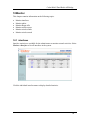
10.1 Interfaces....................................................................................................... 68
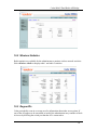
10.2 Wireless Statistics ......................................................................................... 69
10.3 Rogue APs .................................................................................................... 69
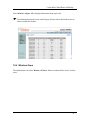
10.4 Wireless Users .............................................................................................. 70
10.5 Wireless Link ................................................................................................ 71
10.6 Wireless Mesh............................................................................................... 73
11 Command Line Interface ............................................................................................ 75
11.1 Base Commands............................................................................................ 75
11.1.1 enable .................................................................................................... 75
11.1.2 disable ................................................................................................... 75
11.1.3 config save ............................................................................................ 75
11.1.4 quit ........................................................................................................ 76
11.1.5 exit......................................................................................................... 76
11.1.6 reboot .................................................................................................... 76
11.1.7 reset ....................................................................................................... 77
11.1.8 up arrow ................................................................................................ 77
11.1.9 down arrow ........................................................................................... 77
11.1.10 debug................................................................................................. 78
11.1.11 undebug............................................................................................. 78
11.1.12 help.................................................................................................... 78
5
Cedar 880AG Dual-Radio AP/Bridge
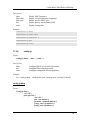
11.2
System Commands........................................................................................ 79
11.2.1 show system .......................................................................................... 79
11.2.2 config system ........................................................................................ 79
11.2.3 show sntp .............................................................................................. 80
11.2.4 config sntp............................................................................................. 80
11.2.5 upgrade.................................................................................................. 81
11.3 Network Commands ..................................................................................... 81
11.3.1 show interface ....................................................................................... 81
11.3.2 config interface ..................................................................................... 82
11.3.3 show vlan .............................................................................................. 82
11.3.4 config vlan ............................................................................................ 83
11.3.5 show ip .................................................................................................. 83
11.3.6 config ip ................................................................................................ 84
11.4 Security Commands ...................................................................................... 86
11.4.1 show auth .............................................................................................. 86
11.4.2 config auth ............................................................................................ 87
11.4.3 show filter ............................................................................................. 90
11.4.4 config filter............................................................................................ 90
11.5 Wireless Commands ..................................................................................... 91
11.5.1 show wireless ........................................................................................ 91
11.5.2 config wireless ...................................................................................... 92
11.5.3 show wlan ............................................................................................. 92
11.5.4 config wlan............................................................................................ 93
11.5.5 show radio............................................................................................. 94
11.5.6 config radio ........................................................................................... 95
11.5.7 show brglnk........................................................................................... 96
11.5.8 config brglnk......................................................................................... 97
11.6 Management Commands .............................................................................. 97
11.6.1 show telnet ............................................................................................ 97
11.6.2 config telnet .......................................................................................... 98
11.6.3 show ssh ................................................................................................ 98
11.6.4 config ssh .............................................................................................. 98
11.6.5 show web .............................................................................................. 99
11.6.6 config web............................................................................................. 99
11.6.7 show snmp ............................................................................................ 99
11.6.8 config snmp......................................................................................... 100
11.6.9 show syslog......................................................................................... 100
11.6.10 config syslog ................................................................................... 101
11.7 Miscellaneous Commands .......................................................................... 101
11.7.1 ping ..................................................................................................... 101
11.7.2 traceroute............................................................................................. 101
11.7.3 show arp .............................................................................................. 102
11.7.4 show memory...................................................................................... 102
11.8 Examples..................................................................................................... 102
11.8.1 System Commands.............................................................................. 102
11.8.2 Network Commands ........................................................................... 103
6
Cedar 880AG Dual-Radio AP/Bridge
11.8.3 802.1x Authentication......................................................................... 104
11.8.4 MAC Authentication........................................................................... 104
11.8.5 WLAN with WPA and 802.1x Authentication ................................... 105
11.8.6 WLAN with WEP and MAC Authentication ..................................... 105
11.8.7 Bridge Link ......................................................................................... 106
11.8.8 Bridge Link with Multiple VLANs..................................................... 106
Appendix I - Recovery Procedure................................................................................... 108
7
Cedar 880AG Dual-Radio AP/Bridge
Introduction
This manual contains information on configuring and managing the Intelicis Enterprise
Dual-Radio Access Point – Cedar880 product family. It is organized into the following
chapters:
•
•
•
•
•
•
•
•
•
•
•
Introduction: Overview of the wireless network and access point deployment
Installation: Description of the Cedar880 hardware
Initial Configuration: Description of Cedar880 initial configuration and the
management interfaces
System: Instructions for changing system parameters
Network: Instructions for changing network parameters
Security: Instructions for configuring RADIUS and authentication profiles
Wireless Network: Instructions for configuring and monitoring wireless network
Management: Instructions for changing management interface settings
Log: Description of the log file
Monitor: Description of how to monitor the system
Command Line Interface: Description of Command Line Interface (CLI) syntax
1.1
Wireless Network
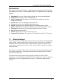
A wireless network is a flexible data communications system that extends the capability
of the existing wired network to provide connectivity for wireless devices. Unlike the
traditional wired network which relies on physical cables and wires to transmit and
receive data, a wireless network relies on radio frequency (RF) technology to transmit
and receive data.
A Wireless Access Point (AP) is a device that connects wireless communication devices.
It is usually connected to a wired network on one end, and relays data to the wireless
network on the other end.
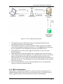
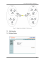
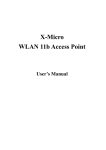
The advent of the wireless network opens up the possibility of what a network
infrastructure can be. Without the restriction of wires, the network can move with users
and change as fast as the organization does. Figure 1.1 illustrates a sample wireless
network.
8
Cedar 880AG Dual-Radio AP/Bridge
Figure 1.1 Wireless Networks
1.2
Wireless LAN Bridge
Cedar Wireless Access Point provides the capability of being configured as a regular
Access Point, a Wireless LAN Bridge or both. A Wireless LAN Bridge wirelessly
connects two ore more Ethernet LANs together. It is a very practical, easy and in most
cases inexpensive way to connect Ethernet LANs or extend the range of existing WLANs.
As illustrated in Figure 1.2 and 1.3, the access point can operate in point-to-point or
point-to-multipoint bridge topology.
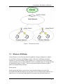
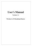
Point-to-point
Point-to-point link allows you to use two access points to bridge two Local Area
Networks from different locations. Access point A serves as a base bridge while Access
point B serves as a non-base bridge. Both access points relay data between the two
9
Cedar 880AG Dual-Radio AP/Bridge
networks. This is an ideal topology for connecting main office with warehouse, or
between office buildings.
Figure 1.2 Point-to-Point Bridge
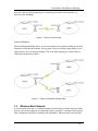
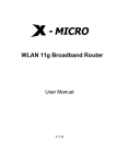
Point-to-Multipoint
Point-to-Multipoint Bridge allows you to use multiple access points to bridge Local Area
Networks from different locations. Access point A serves as a base bridge while Access
point B and C serve as non-base bridges. This is an ideal topology for central office to
collect data from remote offices.
Figure 1.3 Point-to-Multipoint Bridge Mode
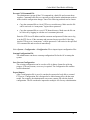
1.3
Wireless Mesh Network
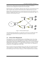
A wireless mesh network is a communications network made up of radio nodes in which
there are at least two pathways of communication to each node. A mesh network requires
little configuration and offers reliability and redundancy. When one node can no longer
10
Cedar 880AG Dual-Radio AP/Bridge
operate, the rest of the network can still communicate. It allows for continuous
connections and reconfiguration around broken or blocked paths.
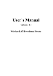
Mesh networks are self-configuring. When the mesh nodes power up, the nodes hear each
other’s broadcast and a network is automatically forms. Mesh networks are also selfhealing. When a node breaks downs or a connections goes bad, the nodes re-discover an
alternative routing path. Network connectivity is thus preserved automatically. Figure 1.4
illustrates a Wireless Mesh Network.
Figure 1.4 Wireless Mesh Network
Cedar 880 dual-radio design allows one radio focus on Wi-Fi access and the other radio
to perform mesh related tasks; thus significantly improves mesh network system
performance.
1.4
Access Point Deployment
The deployment of access point depends greatly on the building structure, the existing
wiring and the type of service to be deployed. For example, RF signals transmit much
easier through a wood-frame building than through a concrete one. For newly constructed
buildings where Ethernet cable CAT 5 is pre-installed, wiring is not a concern. For older
construction, where re-cabling is cost prohibitive, a solution which is less dependent on
wiring such as LAN Bridge may be more viable.
The access point coverage areas should overlap to ensure there are no gaps and roaming
clients always have a connection available. In addition, the number of active wireless
users and the type of service they are using (e.g. VoIP) are important factors to consider.
11
Cedar 880AG Dual-Radio AP/Bridge
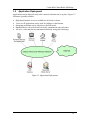
1.5
Application Deployment
Applications can be deployed easily after a network infrastructure is in place. Figure 1.5
illustrates a possible scenario:
•
•
•
•
•
High Speed Internet Access is available for all wireless clients.
Voice over IP applications can be used for calling over the Internet.
Streaming media data can be offered over the IP network.
Handheld devices for mobile staff can easily communicate with each other.
All voice, video and data are transmitted seamlessly using QoS technology.
Figure 1.5 Application Deployments
12
Cedar 880AG Dual-Radio AP/Bridge
2 Installation
This chapter provides instructions on how to install Cedar 880AG.
2.1
Package Contents
Before installation, please inspect the package contents first and report any missing or
damaged items to your sales representative. This package should contain the following:
Cedar 880AG Indoor AP
• Cedar 880AG Dual-Radio Access Point
• Antenna (2)
• Wall Mount Bracket with Mounting Accessories
• Mounting rubber foot (for desktop installation) (4)
• Power Adaptor
• CAT5 Ethernet Cable (RJ45 to RJ45)
• Cedar 880AG Product Resource CD
Cedar 880AG Industrial Edition
•
•
•
•
•
•
•
Cedar 880AG Dual-Radio Access Point
Antenna (2)
Mounting Bracket with Mounting Accessories
CAT5 Ethernet Cable (RJ45 to RJ45)
Waterproof Ethernet Connector
Waterproof Antenna Connector cap
Cedar 880AG Product Resource CD
2.2
Physical Description
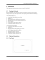
2.2.1 Top Panel
13
Cedar 880AG Dual-Radio AP/Bridge
Figure 2.1 Cedar 880AG Top Panel
•
Power LED
This Power LED is constantly ON when power is applied.
•
Ethernet Link/Activity LED
This LED is ON when Ethernet establishes link; flashing when there is Ethernet
activity.
•
802.11a Wireless LED
This LED is slow flashing when 802.11a wireless is ready for client to associate; fast
flashing when there is traffic on 802.11a wireless.
•
802.11g Wireless LED
This LED is slow flashing when 802.11g wireless is ready for client to associate;
fast flashing when there is traffic on 802.11g wireless.
2.2.2 Rear Panel
•
DC Power Jack (Indoor AP only)
The DC power jack provides the connection to the external 5V DC 2A power supply.
•
Reset Button (Indoor AP only)
The Cedar 880AG rear panel contains one reset button which will reset the unit to the
manufacturer’s default configuration. Press and hold the button down for at least 5
seconds and the unit will automatically reboot and reset to the manufacturer’s default
configuration.
•
RJ45 Connector
The RJ45 connector provides the connection switch or gateway through a CAT 5
cable. This connector also provides the connection to PoE power source.
•
DB9 Connector (Indoor AP only)
This DB9 connector provides the connection to the PC serial port for local
management. A straight RS232 cable is needed (not included in the package).
•
Antenna Connectors
Two reverse polarity TNC jack connectors are provided for connecting to antennas.
The antennas must have a reverse polarity TNC plug connector to be used with Cedar
880AG.
2.2.3 LED Description
14
Cedar 880AG Dual-Radio AP/Bridge
LED
Color
Green, solid
Off
Blue, solid
Flashing
Orange, slow
flashing
Fast flashing
Off
Orange, slow
flashing
Fast flashing
Off
2.3
Indication
The unit power is on.
The unit power is off.
The Ethernet port has successful link.
The Ethernet port is linked and has activity
The 802.11a wireless is ready for client to associate.
There is activity on 802.11a wireless
The 802.11a wireless is not ready.
The 802.11g wireless is ready for client to associate.
There is activity on 802.11g wireless
The 802.11g wireless is not ready.
Install the Unit
2.3.1 Indoor AP Mounting Options
•
•
The Cedar 880AG is designed with two installation options:On desktop or shelf
Wall mount
Mounting Cedar 880AG on desktop or shelf:
• Adhere the 4 mounting rubber feet to the bottom of the unit.
• Place the unit on a secure, flat surface.
Mounting Cedar 880AG on wall:
• At desired wall location, position nails to match the wall mount holes on the bottom
of the unit.
• Secure unit firmly on the nails.
2.3.2 Industrial Edition AP Mounting Options
The Cedar 880AG Industrial Edition is designed with two installation options:
• Wall mount
• Pole mount
Mounting Cedar 880AG Industrial Edition on wall:
• At desired wall location, secure mounting bracket firmly on the wall with nails.
• Match the unit’s 4 copper posts with the bracket holes
• Slide the unit down to secure it onto the bracket
Mounting Cedar 880AG on pole:
• Attach the mounting bracket to the pole with a flexible band (not included)
• Secure the unit firmly to the mounting bracket
15
Cedar 880AG Dual-Radio AP/Bridge
2.3.3 Supplying Power to the Unit
The Indoor Cedar 880AG is equipped with a universal 100-240 VAC, 50/60 Hz power
supply. To power the unit, connect the included power adaptor to the wall outlet and plug
the DC output connector into the power jack on the rear panel of Cedar 880AG.
Cedar 880AG also supports the 802.3af PoE standard. If your switch or gateway has the
capability to supply PoE to remote devices, simply connect the Ethernet cable from your
switch or gateway to the RJ45 connector on the rear panel of Cedar 880AG. This will
automatically supply power to the unit.
2.4
Connecting Cedar 880AG (Indoor AP only)
To establish a connection to Cedar’s console interface, you will need to:
• Connect a regular straight serial cable to the console port located on the rear panel of
the unit.
• Connect the other end of the serial cable to a terminal or PC.
After the unit is turned on, the LEDs on the top panel will follow the pattern described
below:
•
•
•
The Power LED goes on.
The Ethernet LED will be ON if the Ethernet port is connected to a switch or gateway
and a valid link is established.
After 30 seconds, the 802.11a and 802.11g LEDs will be flashing.
16
Cedar 880AG Dual-Radio AP/Bridge
3 Initial Configuration
This chapter contains the following information:
• Discover AP’s IP address using Scan Tool
• Cedar’s default settings
• Web Management Interface
• Command Line Interface
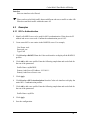
3.1
Scan Tool
Cedar 880AG by default acquires its IP address and subnet mask from the DHCP server.
The administrator can use the Scan Tool to find out the AP’s IP address.
Scan Tool is a utility that is included in the AP CD-ROM. It scans the network and
displays all the available Cedar Access Points. Scan Tool provides the following
functions:
z
z
z
z
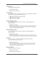
Discover Cedar AP’s IP address, MAC address and firmware version.
Change AP’s IP address.
Upgrade AP’s firmware
Switch on/off AP’s telnet, SNMP and web interface.
Please follow the steps described below to use the Scan Tool:
1.
Insert the installation CD into your CD-ROM drive to install the Scan Tool software.
Follow the on-screen instructions to install Scan Tool on your computer.
2.
Scan Tool requires Java 1.4 or newer version installed on your computer. You can
choose to install Scan Tool along or with the Java software.
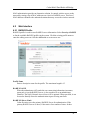
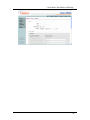
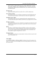
3.
Double click the Scan Tool icon on the desktop to launch the Scan Tool software.
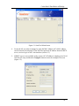
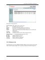
Scan Tool scans the local area network and displays all the Cedar Access Points that
it discovers (Figure 3.1).
17
Cedar 880AG Dual-Radio AP/Bridge
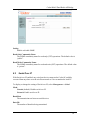
Figure 3.1 Scan Tool Main Screen
4.
Locate the AP you want to manage by using the MAC address (AP’s MAC address
can be found at its back panel). If the AP has acquired an IP address from the DHCP
server, use it to log in to AP’s web interface (section 3.3).
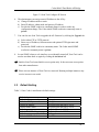
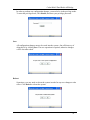
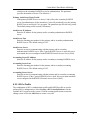
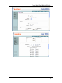
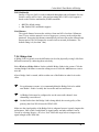
5.
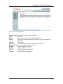
If DHCP server is not available in the system, AP’s IP address is displayed as 0.0.0.0.
Click the AP entry and then the Configure button to enter the configure IP screen
(Figure 3.2).
18
Cedar 880AG Dual-Radio AP/Bridge
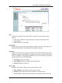
Figure 3.2 Scan Tool Configure IP Screen
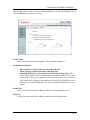
6.
The administrator can assign a static IP address to the AP by :
a) Change IP address mode to static
b) Enter IP address, subnet mask and gateway IP address.
c) Provide the SNMP read/write community name in order to make any
configuration change. The Cedar initial SNMP read/write community name is
private.
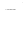
7.
You can also use Scan Tool to upgrade the AP firmware by clicking the Upgrade tab:
a) Select either FTP or TFTP protocol.
b) Enter server IP address, firmware name and optional FTP login name and
password.
c) Provide the SNMP read/write community name. The Cedar initial SNMP
read/write community name is private.
8.
In case SNMP, telnet or web interface are accidentally turned off, Scan Tool can be
used to turn them back on again by clicking the Advanced tab.
) Intelicis Scan Tool scans Intelicis access points only. It does not scan access points
from other manufactures.
) Please run one instance of Scan Tool on a network. Running multiple instances may
receive incorrect scan result.
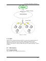
3.2
Default Setting
Table 3.1 lists Cedar’s manufacturer default settings:
Default login name
Default login password
Default enable password
Default IP address
Default subnet mask
Default gateway
Default DNS IP address
Default management VLAN ID
Default SSID for Radio 1
admin
changeitnow
changeitnow
Acquired from the DHCP server.
Acquired from the DHCP server.
Acquired from the DHCP server.
Acquired from the DHCP server
Untagged
Intelicis-a
19
Cedar 880AG Dual-Radio AP/Bridge
Default SSID for Radio 2
Intelicis-g
Table 3.1 Cedar Manufacturer Default Setting
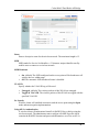
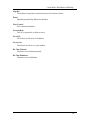
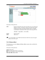
3.3
Web Management Interface
The Cedar Web Management Interface is accessible from any web browser on the
network. Enter the Cedar IP address and port 8080 in the browser address line to activate
the Cedar Web Interface.
You will be prompted for username and password. Enter the default username “admin”
and password “changeitnow”.
After the initial login, the home page is displayed. The administrator now has easy access
to configuring system parameters as well as managing any AP activities.
20
Cedar 880AG Dual-Radio AP/Bridge
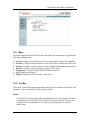
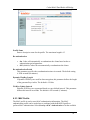
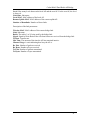
3.3.1 Menu
The menu displayed on the left side of the screen allows the administrator to perform the
following configurations:
•
•
•
•
•
•
•
System: Configure system parameters such as system name, password and upgrade
Network: Configure network parameters such as IP address, default route and VLAN
Security: Configure security parameters such as RADIUS and authentication profiles
Wireless: Configure wireless parameters such as SSID, radios
Management: Configure Telnet, SSH and SNMP parameters
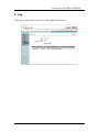
Log: Display system log file
Monitor: Display statistics and usage of the system
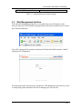
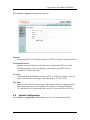
3.3.2 Tool Bar
The tool bar located in the upper right-hand corner provides a shortcut to frequently used
operations. Here is a summary of each of their functions.
Enable
Cedar 880 has two operating modes: normal and privilege. The normal mode allows
the administrator to view most, but not all of the system parameters. The privilege
mode allows the administrator to view all of the system parameters as well as
modify them.
21
Cedar 880AG Dual-Radio AP/Bridge
In order to perform any configuration changes, you need to be in the privilege mode.
To enter the privilege mode, click Enable, and enter your privilege password.
Save
All configuration changes must to be saved into the system. One efficient way of
doing this is by clicking Save. The save operation is required; otherwise changes
will be lost after reboot.
Reboot
Sometimes, you may need to reboot the system in order for any new changes to take
effect. Click Reboot to reboot the system.
22
Cedar 880AG Dual-Radio AP/Bridge
Logout
Click Logout to log out of the system.
Help
Click Help to receive on-line help information.
23
Cedar 880AG Dual-Radio AP/Bridge
4 System
This chapter contains information on the following topics:
•
•
•
•
•
Change system setting
Change password and privilege password
Upgrade
Execute CLI command file
Import/Export configuration file
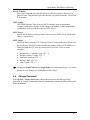
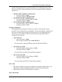
4.1
System Setting
Select System >Setting to change system parameters.
System Name
The System Name is a descriptive string (maximum length of 20) that describes the
system. The default value is <none>.
Login Name
The administrator uses the combination of Login Name and Login Password to log
in to Cedar. After log in, the administrator can view most of the system parameters.
In order to view all of the system parameters and perform any changes, the
administrator needs to enter the privilege mode.
The Login Name may have a maximum length of 31. The default value is “admin”.
24
Cedar 880AG Dual-Radio AP/Bridge
Session Timeout
The Cedar Command Line Interface times out after the session is inactive for a
period of time. This parameter specifies the time out period in minutes. The default
is 10 minutes.
SNTP Setting
This Simple Network Time Protocol (SNTP) setting is used to synchronize
computer clocks on the Internet. If the setting is on (default), Cedar automatically
synchronizes its clock with the reference SNTP Server.
SNTP Server
Specify the IP address or the host name of the reference SNTP Server. The default
value is “time.nist.gov”.
SNTP Offset
The SNTP Server uses the UTC (Universal Time, Coordinated) as the reference for
the current time. The SNTP offset specifies the number of hours to be added to or
subtracted from the UTC time for conversion to local time. Here are some
examples:
•
•
•
•
•
San Francisco, California, USA: UTC - 8
Toronto, Ontario, Canada: UTC - 5
Stockholm, Sweden: UTC + 1
Beijing, China: UTC + 8
Tokyo, Japan: UTC + 9
) Changes to System Name and/or Login Name are saved automatically. You do not
need to save the changes by clicking Save in the tool bar.
4.2
Change Password
Select System > Change Password to change the login password and/or privilege
password. It is highly recommended that the administrator change the default values after
initial installation.
25
Cedar 880AG Dual-Radio AP/Bridge
Login Password
The administrator uses the combination of Login Name and Login Password to log
in to Cedar. After log in, the administrator can view most of the system parameters.
In order to view all of the system parameters and perform any changes, the
administrator needs to enter the privilege mode.
The manufacture default value for Login Password is “changeitnow”.
Privilege Password
The Privilege Password is used by the administrator to enter the privilege mode.
The manufacture default value is “changeitnow”.
) Changes to Login Password and/or Privilege Password are saved automatically.
You do not need to save the changes by clicking Save in the tool bar.
4.3
Upgrade
Intelicis offers free firmware upgrades for bug fixes and patches. Please visit the Intelicis
web site at www.intelicis.com for the latest upgrade. Choose one of the following
methods to download the upgrades.
•
Copy the new firmware to a local FTP server root directory. Make sure the file can be
retrieved via “anonymous” login with no password.
•
Copy the new firmware to a user’s FTP home directory. Make sure the file can be
retrieved by logging in with the user’s username/password.
26
Cedar 880AG Dual-Radio AP/Bridge
Select System > Upgrade to upgrade the firmware.
Protocol
Choose either FTP (File Transfer Protocol) or TFTP (Trivial File Transfer Protocol).
Username/Password
Enter the username and password Cedar uses to log into the FTP server. If the
username and password are not specified, Cedar logs in to the FTP server as
“anonymous” with no password.
Server IP
The Server IP is the IP address of the local FTP or TFTP server where Cedar can
retrieve the firmware. An example of the Server IP is 192.168.15.184.
File Name
Enter the Cedar 880AG firmware name. The firmware name is composed of three
parts: model name-date-version number. For example, cedar880ag-093020051.1.0.88a.bin refers to Cedar model 880 version 1.1.0.88 created on 09/30/2005.
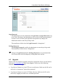
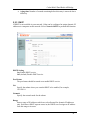
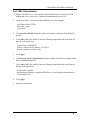
4.4
System Configuration
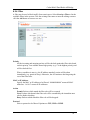
Select System > Configuration>CLI Script to execute CLI command batch files.
27
Cedar 880AG Dual-Radio AP/Bridge
Execute CLI Command File
The administrator can put all the CLI commands in a batch file and execute them
together. Command batch files are especially useful when the administrator needs to
make sizeable configuration changes. One of the following methods can be chosen:
•
Copy the command file to a local FTP server root directory. Make sure the file
can be retrieved via “anonymous” login with no password.
•
Copy the command file to a user’s FTP home directory. Make sure the file can
be retrieved by logging in with the user’s username/password.
Enter the FTP Server IP address and the username and password Cedar uses to log
in to the FTP Server. If the username and password are not specified, Cedar logs
into the FTP server as “anonymous” with no password. Cedar retrieves the specified
CLI command file and executes it immediately.
Select System > Configuration > Configuration File to import/export configuration files.
Startup Configuration File
The administrator can choose a startup configuration file for the AP to startup the
system.
Save Current Configuration
The existing configuration can be saved to a file in binary format for archiving
purpose. If for any reasons, a recovery is required. The configuration file contains
useful information.
Export/Import
After a configuration file is saved, it can then be exported to local disk or external
FTP server. Configuration file is designed to be shared among APs with the same
model. For example, the administration can create a master file with the desired
configuration. The file can then be imported to multiple APs for easy administration.
28
Cedar 880AG Dual-Radio AP/Bridge
5 Network
This chapter contains information on the following topics:
•
•
•
Change network settings
Configure VLAN
Configure DHCP Server
5.1
Overview
5.1.1 VLAN
Virtual LAN (VLAN) logically groups users by their functionality instead of physical
location. VLAN uses software to configure logical topologies on top of the physical
network infrastructure. Users grouped into one VLAN may be located on different floors
or in different buildings. However, all users on one VLAN can communicate with each
other as if they were all on the same physical LAN.
The same concept extends to a wireless network. Wireless clients can be grouped into
wireless sub-networks. A client can access the network by connecting to an AP which
supports its assigned VLAN (see Figure 5.1).
VLANs provide many benefits:
•
VLANs increase performance by limiting broadcast traffic for both wired and
wireless networks.
•
VLANs improve manageability by providing an easy, flexible way to modify logical
groups in changing environments. When a computer is physically moved to another
location, it can stay on the same VLAN without any hardware reconfiguration.
•
VLANs increase security options. Broadcast traffic is only broadcast within the
VLAN. This allows the network administrator to segment users requiring access to
sensitive information into VLANs separate from the rest of the community.
29
Cedar 880AG Dual-Radio AP/Bridge
Figure 5.1 VLANs
5.1.2 DHCP
Dynamic Host Configuration Protocol (DHCP) is a protocol for assigning dynamic IP
addresses to computers on a network. Dynamic addressing simplifies network
administration because the software keeps track of IP addresses. This means a new
computer can be added to a network without the hassle of manually assigning it a unique
IP address.
5.2
Web Interface
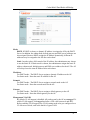
5.2.1 Network Setting
Select Network > IP to change network parameters.
30
Cedar 880AG Dual-Radio AP/Bridge
Mode:
DHCP: If DHCP is chosen, a dynamic IP address is assigned to AP by the DHCP
Server. In addition, the subnet mask, default gateway and DNS server addresses are
also assigned. Because DHCP assigns the IP address dynamically, different IP
addresses may be assigned to the AP after each reboot.
Static: In order to have full control of the IP address, the administrator may choose
to use the Static IP. If Static mode is chosen, the administrator assigns the static IP
address, subnet mask, default gateway and DNS server address for the AP. The AP
will always have the same IP address after each reboot.
IP address
For DHCP mode: The DHCP Server assigns a dynamic IP address to the AP.
For Static mode: Enter the static IP address for the AP.
Netmask
For DHCP mode: The DHCP Server assigns a network mask to the AP.
For Static mode: Enter the network mask for the AP.
Gateway
For DHCP mode: The DHCP Server assigns a default gateway to the AP.
For Static mode: Enter the default gateway for the AP.
Management VLAN ID
By default, VLAN support is disabled. All packets sent by the AP are untagged. To
enable VLAN support, click tagged and enter a VID value between 0 and 4095.
Before enabling VLAN support, the VLAN setting needs to be pre-configured on a
VLAN-aware switch, such as the Intelicis Cypress 1024.
31
Cedar 880AG Dual-Radio AP/Bridge
Primary or Secondary DNS
Optionally enter the primary or secondary Domain Name Server (DNS) IP address.
DNS translates domain names into IP addresses. Using DNS, network users are
allowed to use more descriptive names such as www.example.com rather than
198.105.232.4.
5.2.2 VLAN
Select Network->VLAN to display the Virtual LANs in the system.
By default, VLAN support is disabled in Cedar. In this case, a single lan with the VLAN
ID untagged is displayed.
After the administrator enables VLAN support, additional VLANs are created by the
system. The generated VLAN name has the following format:
vlan<vlan id>
Some examples would be vlan88 and vlan99.
Click the VLAN name to display detailed VLAN information.
32
Cedar 880AG Dual-Radio AP/Bridge
STP
The 802.1d Spanning Tree Protocol (STP) is used to prevent interfaces from
looping.
• On: STP is enabled. If a loop is detected, one of the connections will be
disconnected.
• Off: (default) STP is disabled.
Aging Time
Specify how long an inactive MAC address remains in the MAC table before it is
removed from the table. The default is 300 seconds (5 minutes).
Interfaces
Display a list of interfaces associated with this VLAN. The system initially comes
with three interfaces: eth0 (Ethernet), wlan0 (wireless radio 1) and wlan1 (wireless
radio 2). Enabling VLAN support automatically creates new interfaces. The status
of each interface is one of the following:
•
•
•
Learning: Interface is learning.
Forwarding: Interface is actively forwarding packets.
Blocked: Interface is blocked.
MAC Table
Displays a list of MAC addresses associated with this VLAN.
•
•
•
MAC Address: MAC address of the client’s machine
Interface: The interface the client’s machine is associated with
Local: Whether or not the client’s machine is associated with the AP locally
33
Cedar 880AG Dual-Radio AP/Bridge
•
Aging time: Number of seconds remaining before this entry is removed due to
inactivity
5.2.3 DHCP
If DHCP is not available in your network, Cedar can be configured to assign dynamic IP
addresses to computers on the network. Select Network>DHCP to perform this function.
DHCP Setting
On: Enable DHCP service.
Off: (default) Disable DHCP service.
Pool Status
The pool status should be turned on to enable DHCP service.
Net
Specify the subnet where you want the DHCP to be enabled, for example,
192.168.1.0.
Netmask
Specify the network mask for the subnet.
Range
Enter a range of IP addresses which are to be allocated for dynamic IP addresses
only. Each time a DHCP request comes in; the DHCP server assigns an IP address
from this range to its users.
34
Cedar 880AG Dual-Radio AP/Bridge
Gateway
Enter the default gateway IP address which the DHCP server will assign to its users.
DNS
Enter the DNS IP address which the DHCP server will assign to its users.
WINS
Enter the Windows Internet Name Server IP address which the DHCP server will
assign to its Windows users.
Lease Time
Enter how long the assigned IP address is valid for. The default is 1800 seconds (30
minutes).
5.3
Examples
5.3.1 Configure Static IP Address
1
Consult your ISP or IT department to acquire a static IP address, network mask,
default gateway and DNS for your AP.
2
Click Network->IP from the Cedar web interface to modify the network settings.
3
Select Static as the network mode. The three parameters of IP, Network Mask and
Gateway become enabled.
4
Enter the IP, Network Mask and Gateway parameters.
5
Optionally enter the DNS parameters.
6
Click Apply.
7
The address change takes effect immediately. You will need to re-login using the new
IP address to continue with the rest of the configuration.
8
Save the configuration.
5.3.2 Configure Management VLAN ID
1.
Consult your IT department to acquire the VLAN ID setting. Make sure the device
(e.g. switch) that the AP connects to will support VLAN. The VLAN ID needs to be
pre-configured there.
35
Cedar 880AG Dual-Radio AP/Bridge
2.
Click Network->IP from Cedar web interface to modify the network settings.
3.
Select Tagged, and enter the VLAN ID.
4.
The VLAN ID change takes effect immediately. You will need to change the port
which the AP is using to a trunk port.
5.
Save the configuration.
36
Cedar 880AG Dual-Radio AP/Bridge
6 Security
This chapter contains information on the following topics:
•
•
•
•
Configure RADIUS profile
Configure 802.1x authentication
Configure MAC authentication
Configure Filter to block certain traffic
6.1
Overview
6.1.1 802.1x Authentication
Wireless Networks provide enormous flexibility, but they can also create potential
security problems in the network. Extensible Authentication Protocol (EAP) is an
authentication method that addresses the security issues in the wireless network. It is part
of the 802.1x WLAN standards defined by IEEE.
The IEEE 802.1x specification uses three important terms. The user or client who wants
to be authenticated is called a supplicant. The actual server doing the authentication,
typically a RADIUS server, is called the authentication server. And the device in between,
such as a wireless access point, is called the authenticator. One of the key points of
802.1x is that the authenticator can be small and simple - all of the processing is done by
the supplicant and the authentication server. This makes 802.1x ideal for wireless access
points, which are typically small and have limited memory and processing power.
Figure 6.1 illustrates a simple 802.1x authentication sequence.
37
Cedar 880AG Dual-Radio AP/Bridge
Figure 6.1 802.1x authentication sequence
1.
2.
3.
4.
5.
The supplicant sends an authentication request containing identification and
connection information to the authenticator.
The authenticator performs an initial negotiation with the supplicant to establish
connection information (username, password, etc). The authenticator then forwards
the user information in an authentication request to the RADIUS Server.
The RADIUS Server looks up the supplicant information in a local or remote
RADIUS database.
If the information is found, the RADIUS server responds with a success message,
which is then passed onto the supplicant. The authenticator now allows access to the
network with possible restrictions based on attributes that came back from the
authentication server. For example, the authenticator might switch the supplicant to a
particular virtual LAN. If the information is not found, the RADIUS server responds
with a reject message.
Based on the information it receives from the RADIUS server, the authenticator
accepts or refuses the connection request.
6.1.2 MAC Authentication
Although 802.1x authentication addresses security issue for the wireless network, its
implementation may not be practical for every wireless devices (e.g. PDA) because it
requires supplicant software to be installed on all wireless client machines.
38
Cedar 880AG Dual-Radio AP/Bridge
MAC authentication provides an alternative solution. It controls wireless access to the
network by storing a list of MAC addresses on a local or RADIUS server. This list of
MAC addresses identifies the authorized stations that may access the wireless network.
6.2
Web Interface
6.2.1 RADIUS Profile
RADIUS profile is used to store RADIUS server information. Select Security->RADIUS
to list the available RADIUS profiles in the system. Click the existing profile name to
enter the editing screen or click the Add button to create a new one.
Profile Name
Enter a descriptive name for the profile. The maximum length is 15.
RADIUS NAS IP
When the authenticator (AP) sends the user connection information (username,
password, etc) to the RADIUS server, it also sends its IP as an authenticator
identifier. The NAS (Network Access Server) IP is optional. When specified, it can
be used to identify where the authentication request is being sent from.
RADIUS Failover Limit
Cedar first tries to use the primary RADIUS Server for authentication. If the
primary RADIUS server is down, Cedar retries for a number of times. It then
39
Cedar 880AG Dual-Radio AP/Bridge
switches to the secondary RADIUS server for authentication. The parameter
specifies the number of retries. The default is 4.
Primary Auth Server Retry Period
If the primary RADIUS server is down, Cedar will use the secondary RADIUS
server for authentication. In the meantime, Cedar will periodically retry the primary
RADIUS server and check if it is up again. The parameter specifies the retry period.
The default setting is 600 seconds (10 minutes).
Auth Server IP Address
Enter the IP address for the primary and/or secondary authentication RADIUS
server.
Auth Server Port
Enter the listening port number for the primary and/or secondary authentication
RADIUS server. The default setting is 1812.
Auth Server Secret
Enter the secret for communicating with the primary and/or secondary
authentication RADIUS server. If the Cypress RADIUS server is used, this secret
must match the secret configured in the RADIUS Network Access Server (NAS).
Accounting Server IP Address
Enter the IP address for the primary and/or secondary accounting RADIUS server.
Accounting Server Port
Enter the listening port number for the primary and/or secondary accounting
RADIUS server. The default setting is 1813.
Accounting Server Secret
Enter the secret for communicating with the primary and/or secondary accounting
RADIUS server. If the Cypress RADIUS server is used, this secret must match the
secret configured in the RADIUS Network Access Server (NAS).
6.2.2 802.1x Profile
The combination of 802.1x authentication profile and RADIUS profile are used to
perform 802.1x authentication. Select Security->802.1x Authentication to list the
available 802.1x profiles in the system. Click the existing profile name to enter the
editing screen or click the Add button to create a new one.
40
Cedar 880AG Dual-Radio AP/Bridge
Profile Name
Enter a descriptive name for the profile. The maximum length is 15.
Re-authentication
•
•
On: Cedar will automatically re-authenticate the clients based on the reauthentication period parameter.
Off: (default) Cedar will not automatically re-authenticate the clients.
Re-authentication Period
This parameter specifies the re-authentication timer in seconds. The default setting
is 3600 seconds (60 minutes).
Dynamic WepKey Length
If dynamic WEP keys are used for data encryption, this parameter defines the length
of the generated keys in bits. The default is 128 bits.
WebKey Update Interval
Dynamic WEP keys are regenerated based on a pre-defined interval. This parameter
defines this interval in seconds. The default is 300 seconds (5 minutes).
6.2.3 MAC Profile
The MAC profile is used to store MAC authentication information. The MAC
authentication profile can be used alone or combined with the RADIUS profile to
perform MAC authentication. Select Security->MAC Authentication to list the available
41
Cedar 880AG Dual-Radio AP/Bridge
MAC profiles in the system. Click the existing profile name to enter the editing screen or
click the Add button to create a new one.
Profile Name
Enter a descriptive name for the profile. The maximum length is 15.
Authentication Method
•
•
•
Reject all users except for the ones on the Permit List.
Allow all users except for the ones on the Deny List.
Consult RADIUS Server if not found on the Permit or Deny Lists: The
client’s MAC address is first checked against the Permit and Deny Lists. If it is
on the Permit List, access is granted. If it is on the Deny List, access is denied.
If the client’s MAC address is on neither one of the lists, the RADIUS server is
checked. If it is on the RADIUS server, access is granted, otherwise, access is
denied.
Permit List
A local list of the entire MAC addresses which are to be permitted access.
Deny List
A local list of the entire MAC addresses which are to be denied access.
42
Cedar 880AG Dual-Radio AP/Bridge
6.2.4 Filter
A filter may be used to block traffic from certain users. Select Security->Filter to list the
available filters in the system. Click the existing filter name to enter the editing screen or
click the Add button to create a new one.
Priority
All the incoming and outgoing packets will be checked against the filter rules based
on their priority. Low number means high priority (e.g. 1 is the highest priority) and
will be checked first.
When a condition is met (e.g. the IP address matched), action will be taken
immediately (e.g. permit or deny). Otherwise, the AP continues checking using the
rest of the filter rules.
MAC or IP Address
Specify the MAC or IP address to be filtered. “000000000000” means all MAC
addresses. “0.0.0.0” means all IP addresses.
Action
Permit: Packets which match the filter rule will be accepted.
Next: Packets which match the filter rule will be examined by the immediate next
rule for further checking.
Deny: Packets which match the filter rule will be dropped.
Protocol
Select a protocol to be filtered. Options are TCP, UDP or ICMP.
43
Cedar 880AG Dual-Radio AP/Bridge
Interface
Select an interface to be filtered.
) Filter can be used to block traffic between different sub-nets or traffic to other APs.
Filter does not block traffic within the same AP.
6.3
Examples
6.3.1 802.1x Authentication
1
Identify a RADIUS server to be used for 802.1x authentication. Write down its IP
address and server secret code. Confirm the authentication port is 1812.
2
Create some 802.1x user entries in the RADIUS server. For example,
User Name: test1
Password: xxx
Type: EAP
3
Click Security->RADIUS from the Cedar web interface to display all the RAIDUS
profiles.
4
Click Add to add a new profile. Enter the following sample data and use default for
the rest of the parameters.
Profile Name: myRADIUS
Primary Auth Server IP Address: 192.168.1.1
Primary Auth Server Secret: xxxx
5
Click Apply.
6
Click Security->802.1x Authentication from the Cedar web interface to display the
entire 802.1 x authentication profiles.
7
Click Add to add a new profile. Enter the following sample data and use default for
the rest of the parameters.
Profile Name: my8021x
8
Click Apply.
9
Save the configuration.
44
Cedar 880AG Dual-Radio AP/Bridge
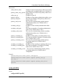
6.3.2 MAC Authentication
1
Identify a RADIUS server to be used for MAC authentication. Write down its IP
address and server secret code. Confirm the authentication port is 1812.
2
Create some MAC user entries in the RADIUS server. For example,
User Name: 000cf157b3bc
Password: <none>
Type: MAC
3
Click Security->RADIUS from the Cedar web interface to display all the RADIUS
profiles.
4
Click Add to add a new profile. Enter the following sample data and use default for
the rest of the parameters.
Profile Name: myRADIUS
Primary Auth Server IP Address: 192.168.1.1
Primary Auth Server Secret: xxxx
5
Click Apply.
6
Click Security->MAC Authentication from the Cedar web interface to display all the
MAC authentication profiles.
7
Click Add to add a new profile. Enter the following sample data and use default for
the rest of the parameters.
Profile Name: myMAC
Authentication Method: Consult RADIUS Server if not found on the permitted or
rejected MAC lists.
8
Click Apply.
9
Save the configuration.
45
Cedar 880AG Dual-Radio AP/Bridge
7 Wireless
This chapter contains information on the following topics:
•
•
•
•
•
Configure Wireless Setting
Configure WLAN
Configure Radio 1 and 2
Configure Bridge Link
Configure Mesh
7.1
Overview
7.1.1 WLAN
Similar to the Virtual LAN concept, WLAN is a way to logically group wireless users
into sub-networks. Each WLAN may implement a different security mechanism and has a
different level of access to the network. The administrator can selectively enable a list of
WLANs on the AP. A wireless user is allowed to access the wireless network by
connecting to an AP which supports his assigned WLAN.
A RADIUS server can be used to enforce WLAN access control. When a wireless user
connects to the AP using a WLAN, he may or may not be authorized to use that WLAN.
During the authentication phase, the RADIUS server not only authenticates the user but
also returns user attributes (e.g. the user’s VLAN ID) to the authenticator (AP). The AP
can subsequently determine whether to allow the user access to the wireless network.
7.1.2 Bridge Link
Bridge Link is a cost effective way to connect Ethernet LANs from difference location
using wireless devices. As described in Chapter 1, bridge link can work in a point-topoint or point-to-multipoint topology. You can use either topology to support:
z Single VLAN network: untagged packets are sent across the wireless bridge link.
z Multiple VLANs network: tagged packets are sent across the wireless bridge link.
Figure 7.1 illustrates a point-to-point bridge link topology supporting multiple VLANs
network.
46
Cedar 880AG Dual-Radio AP/Bridge
Figure 7.1 Bridge Link in Multiple VLANs Network
7.2
Web Interface
7.2.1 Wireless Setting
47
Cedar 880AG Dual-Radio AP/Bridge
Wireless Setting
On: (default) Enable the wireless service.
Off: Disable the wireless service.
Wireless Status
Display the status of the wireless service.
Country Code
Display the AP’s country code. The country code is set during the manufacture
stage and can not be modified by the users.
80211d World Mode
If world mode is turned on, the AP broadcasts its local settings, such as the country
code. The default setting is off.
EAP Relay
If EAP relay is turned on, the AP does not perform any EAP related authentication.
Instead, the AP relays the requests to a wireless switch and relies on the switch to
perform this function. The default setting is off.
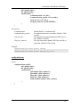
7.2.2 WLAN
WLANs logically group users by their functionality. Each group may have a different
access privilege, security level and encryption method. Select Wireless->WLAN to list
the available WLANs in the system. Click the existing WLAN name to enter the editing
screen or click the Add button to create a new one.
After a WLAN is created, add it to either one of the Radios to take effect. The system
comes with the following two default WLANs:
•
•
Intelicis-a: used by Radio 1
Intelicis-b: used by Radio 2
48
Cedar 880AG Dual-Radio AP/Bridge
49
Cedar 880AG Dual-Radio AP/Bridge
Name
Enter a descriptive name for the wireless network. The maximum length is 12.
SSID
SSID stands for Service Set Identifier, a 32 character unique identifier used by
mobile users to connect to a wireless network.
SSID Broadcast
•
•
On: (default) The SSID configured on the access point will be broadcast to all
wireless devices within range.
Off: The automatic SSID broadcast feature is disabled.
VLAN ID
Specify whether the VLAN ID tag will be used.
•
•
Untagged: (default) The wireless packets of this WLAN are untagged.
Tagged & VLAN ID: The wireless packets of this WLAN are tagged with the
specified VLAN ID.
No Security
Wireless clients will establish association with the access point using the Open
mode and no encryption implementation.
Using 802.1x Authentication
A wireless client will authenticate himself via RADIUS Server before using the
wireless network. The administrator must configure a RADIUS profile which
contains the RADIUS location and password information, as well as an 802.1x
50
Cedar 880AG Dual-Radio AP/Bridge
profile which contains 802.1x specific information. The administrator may select
one, two or all three of the association mode and encryption method combinations
listed below:
•
•
•
Dynamic WEP with 802.1x authentication
o association mode is Open
o encryption method is Dynamic WEP
WPA/TKIP with 802.1x authentication
o association mode is Wi-Fi Alliance’s WPA
o encryption method is TKIP
WPA2/AES with 802.1x authentication
o association mode is Wi-Fi Alliance’s WPA2
o encryption method is AES
Using Key/Passphrase
The authentication mechanism used between wireless clients and the wireless
network is a pre-configured key or passphrase. The key or passphrase configured on
the client’s machine must match those stored on the AP. The administrator may
choose one, two or all three of the association mode and encryption method
combinations listed below:
•
Static WEP key
o association mode is Open
o data encryption method used is Static WEP key
You must choose a default WEP Key index and fill in the WEP key.
•
WPA/TKIP with PSK
o association mode is Wi-Fi Alliance’s WPA
o encryption method is TKIP.
You must fill in the WPA Pre-Shared-Key Passphrase.
•
WPA2/AES with PSK
o association mode is Wi-Fi Alliance’s WPA2
o encryption method is AES
You must fill in the WPA2 Pre-Shared-Key Passphase.
MAC Auth
•
•
On: wireless clients are required to authenticate using their MAC address. You
must choose a MAC authentication profile to be used for authentication.
Off: (default) No MAC authentication is performed.
MAC Auth Profile
51
Cedar 880AG Dual-Radio AP/Bridge
Specify the MAC authentication profile to be used for authentication. You must
have already configured a MAC authentication profile in the system. If the MAC
authentication method requires the RADIUS Server, you will also need to specify
the RADIUS profile.
RADIUS Profile
Specify the RADIUS profile to be used for 802.1x or MAC authentication.
Forced Unicast Tx Rate
This parameter allows you to configure a transmission rate (in 100 kbps) that will
be used for all unicast frames. The rate must be one of the AP’s supported rates.
Maximum Unicast Tx Rate
This parameter allows you to set a maximum limit on the transmission rate to be
used. By default, this option is disabled, which allows any supported rate to be used.
Min Rate to Associate
This parameter allows you to set a minimum rate required for association. If a client
station does not support any rates equal to or greater than this rate, the association
will be rejected.
DTIM
The Delivery Traffic Indication Message (DTIM) is used by the AP to indicates
which client station, currently sleeping in low-power mode, have data buffered on
the access point waiting for pick-up. DTIM should be left at 2, the default value.
This parameter supports a range between 1 and 255.
Maximum Stations
This parameter specifies the maximum number of stations which can associate with
the AP. The default is 256.
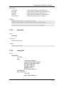
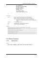
7.2.3 Radio
Select Wireless->Radio 1 or Wireless->Radio 2 to display radio specific parameters for
radio 1 or 2. Except for WLAN and Bridge Link, most of the parameters can be left with
their default values.
52
Cedar 880AG Dual-Radio AP/Bridge
53
Cedar 880AG Dual-Radio AP/Bridge
RF
Enable or disable the radio.
•
•
On: the default setting
Off: disables the radio
Frequency
Select one of the communication modes between wireless clients and the Access
Point. Radio 1 operates in frequency a or super-ag. Radio 2 operates in frequency
b, g, bg or super-ag.
•
•
•
•
•
a: The default setting for Radio 1.
b: The radio supports 802.11b standard only.
g: The radio supports 802.11g standard only.
bg: The default setting for Radio 2. Choose bg if you want to support both
802.11b and 802.11g devices.
super-ag: Enabling Super AG provides better performance by increasing radio
throughput.
Channel
Select a channel for the AP. If auto is selected, the AP automatically chooses a
relatively unused channel. The administrator can specify a list of “preferred”
channels using Auto Channel List that you wish the AP to scan first. Channels not
in the Auto Channel List will not be chosen by the AP.
If the administrator wants to manually set the channel, he needs to ensure that
nearby devices do not use the same channel.
If bridge link is configured, all bridge links need to communicate on the same
channel.
54
Cedar 880AG Dual-Radio AP/Bridge
•
•
•
•
•
Auto: the default setting. It allows the AP to select a free or relatively unused
communication channel. Channels in the Auto Channel List are preferred
channels and will be scanned first.
1-14: used for frequencies b, g, and bg
36, 40, 44, 48, 52, 56, 60, 64, 100, 104, 108, 112, 116, 120, 124, 149, 153, 157,
161, 165: used for frequency a
40, 48, 56, 153, 161: used for frequency super-ag (radio 1)
6: used for frequency super-ag (radio 2)
) The channel regulation varies for every country. AP only allows you to set the
channel that is legal in your country.
Transmit Power
Under certain circumstances, you may want to reduce the transmit power. An
example would be when two radios are transmitting and receiving on nearby
channels. To prevent one radio from interfering with the other, you may want to
reduce its power.
•
•
Auto: the default setting
1-20 dbm
Mode
Select one of the operating modes for AP. The AP can operate as a regular AP, a
Bridge or both.
AP: The AP operates as a regular access point.
BRGLNK: The AP operates as a Bridge.
AP, BRGLNK: The AP operates as both AP and Bridge.
Role
In a point-to-point or point-to-multipoint bridge link environment, one of the
bridges has to be the base bridge. The rest of the bridges which associate with the
base bridge become non-base bridges.
Base: The AP operates as a base bridge.
Non-Base: The AP associates with the base bridge.
Repeater
A repeater is not connected to a wired LAN. When an AP is configured as a
repeater, its Ethernet port does not function. It has to reply on other Bridge or AP to
forward packets.
On: Enable repeater mode.
Off: The default setting.
WLAN
55
Cedar 880AG Dual-Radio AP/Bridge
•
•
Add a WLAN to this Radio from the available WLAN list.
Delete a WLAN from this Radio.
Bridge Link
•
•
Add a Bridge Link to this Radio from the available Bridge Link list.
Delete a Bridge Link from this Radio.
Auto Channel List
Auto Channel List is a list of preferred channels that the administrator wishes the
AP to scan first when channel is set to “Auto”.
•
•
1-14: used for frequencies b, g, and bg
36, 40, 44, 48, 52, 56, 60, 64, 149, 153, 157, 161, 165: used for frequency a
Tx Rates
Select a frequency allows the AP to automatically set the default basic and
supported rates. The user can then further fine tune the rates.
•
•
•
•
6, 9, 12, 18, 24, 36, 48, 54: for frequency a
1, 2, 5.5 or 11: for frequency b
6, 9, 12, 18, 24, 36, 48, 54: for frequency g
1, 2, 5.5, 6, 9, 11, 12, 18, 24, 36, 48 or 54: for frequency bg
Beacon
Beacon frames are transmitted by an AP at regular intervals to announce the
existence of the wireless network. This parameter has a range of 20 to 1000 ms. The
default setting is to send a beacon once every 100 ms.
Preamble
The preamble is used to allow stations to synchronize with the access point signal.
•
•
Long: The long preamble uses the legacy 802.11 1 and 2 Mbps DSSS header.
Short: The short preamble is provided to improve the efficiency of the
network’s throughput.
Fragmentation Threshold
The fragmentation threshold limits the size of packets transmitted on the network. If
a packet exceeds the threshold, packet will be fragmented and sent as multiple
frames. The range is 256 to 2346. The default setting is 2346.
RTS Threshold
RTS/CTS (Request to Send/Clear to Send) are used to control station access to the
AP. A station initiates the process by sending a RTS. The AP receives the RTS and
responds with a CTS. The station must receive a CTS frame before sending data.
The range is 0 to 2347. When set to 2347 (the default setting), RTS is disabled.
56
Cedar 880AG Dual-Radio AP/Bridge
CTS Protection
See description in RTS threshold.
•
•
On: The default setting.
Off: Disable CTS protection.
Antenna Setting
Antenna diversity improves performance of the AP by automatically selecting the
best antenna for signal reception and transmission.
•
•
•
Diversity: (default) Enable antenna diversity.
Ant1: Always uses antenna 1.
Ant2: Always uses antenna 2.
Channel Utilization to Drop
This load balancing feature attempts to maintain a useable throughput for a
particular channel.
•
•
Off: The default setting.
On: Specify the parameter in percentage. If the air time related load is greater
than the given threshold, disassociate a station. Stations that are sleeping in
power-save mode are disassociated first.
Channel Utilization to Deny
This load balancing feature attempts to maintain a useable throughput for a
particular channel.
•
•
Off: The default setting.
On: Specify the parameter in percentage. If the air time related load is greater
than the given threshold, new stations are not allowed to associate with the AP.
Intra BSS
For security reasons, sometimes the administrator may need to disable
communication between wireless clients.
•
•
On: The default setting.
Off: The AP blocks communication between wireless clients. Data traffic is
allowed between the AP and its wireless clients and wired devices on the
network, but not among wireless clients.
Rogue AP Detection
Enable/disable rogue AP detection.
•
•
Off: The default setting.
On: Enable rogue AP detection.
57
Cedar 880AG Dual-Radio AP/Bridge
WiFi Multimedia
Quality of Service (QoS) is used to enhanced throughput and performance for time
sensitive traffic such as voice, video and streaming data. Cedar’s QoS support is
based on the Wireless multimedia (WMM) standards.
•
•
Off: The default setting.
On: Enable WiFi multimedia support.
Link Distance
The typical distance between the wireless clients and AP is less than 1 kilometer
(km). If your wireless network covers a bigger area, you may need to adjust this
parameter. Increasing link distance automatically increases the packet acknowledge
timeout period. This will impact the overall wireless network performance. The
default setting is 0 (less than 1 km).
7.2.4 Bridge Link
A Bridge Link can greatly ease the difficulties involved in physically wiring LANs from
different locations by connecting them wirelessly.
Select Wireless->Bridge Link to list the available Bridge Links in the system. Click the
existing Bridge Link name to enter the editing screen or click the Add button to create a
new one.
After a Bridge Link is created, add it to either one of the Radios in order for it to take
effect.
)
)
)
For performance reasons, it is recommended that the Bridge Link to be added
onto Radio 1. Radio 1 usually has less traffic and less interference.
All Bridge Links must be configured to use the same radio channel. Auto
channeling is not allowed.
On the Radio where the Bridge Link is being added, the security policy of the
primary (the first) WLAN must be WPA2/AES.
Make sure the signal quality of the Bridge Link is adequate because it greatly impacts the
performance. Once a link is established, its signal quality and other statistics can be
viewed by selecting Monitor->Wireless Link. Follow the steps below to improve the
signal strength of the WDS link:
58
Cedar 880AG Dual-Radio AP/Bridge
•
•
•
•
The two APs should be placed such that there are minimal objects between them.
Any steel or wood objects absorb RF energy. You should also consider radio
interference from devices such as microwave ovens or other APs.
Scan the channel activities to select a channel that is least busy.
Adjust the power level setting when the distance of the two APs changes; the
further the distance, the higher the power.
Adjust the link distance parameter as you see fit.
Name
Enter a descriptive name for the Bridge Link. The maximum length is 7.
Link SSID
Enter the SSID to be used between the base and non-base bridges. Each bride link
should have its own SSID configured.
Security Key
Enter the security key used between the base and non-base bridges. The security
key should be 8 to 63 characters long.
7.2.5 Mesh
In a mesh network, access points self configure and maintain their connectivity with
adjacent access points via reliable, high-speed wireless links. When selecting an adjacent
AP, factors such as signal strength and location are calculated to determine the most
efficient path.
Select Wireless->Mesh to display mesh network setting.
59
Cedar 880AG Dual-Radio AP/Bridge
)
All changes are required to save configuration and reboot to take effect.
Setting
On: Enable the mesh function.
Off: (default) Disable the mesh function.
Radio
Choose a radio to perform the mesh function.
Role
In a mesh network, at least one access point has to be the root. The rest of the APs
maintain wireless links with the root AP or other non-root AP.
Root: The root AP usually has the direct connection with the corporate network.
Non-Root: The non-root AP maintains wireless links with the root AP or other nonroot AP.
Channel
The root AP selects its own channel. The non-root AP uses whatever channel that is
chosen by the root AP.
Minimum Link SNR
When a non-root AP selects an adjacent AP to establish wireless link, the signal
strength is one of the major factor. Any adjacent AP with link quality below
Minimum Link SNR will not be used to establish mesh link.
7.3
Examples
7.3.1 WLAN with WPA and 802.1x Authentication
You should already have a RADIUS profile and an 802.1x authentication profile
configured in the system.
1
Click Wireless->WLAN from the Cedar web interface to display all the WLANs.
2
Click Add to add a new profile. Enter the following sample data and use defaults for
the remainder of the parameters.
Name: myWLAN
SSID: myWLAN
3
Select Using 802.1x Authentication for security policy. The parameters in this subsection become enabled.
60
Cedar 880AG Dual-Radio AP/Bridge
4
Click WPA/TKIP with 802.1x Authentication, and select an 802.1x Auth Profile
from the list box.
5
Select a RADIUS Profile from the list box.
6
Click Apply.
7
Click Wireless->Radio 2 from the Cedar web interface to display radio 2 parameters.
8
Click myWLAN from the available WLAN list box and add it to the selected WLAN
list box.
9
Click Apply.
10 Save the configuration.
7.3.2 WLAN with WEP and MAC Authentication
You should already have a RADIUS profile and an MAC authentication profile
configured in the system.
1
Click Wireless->WLAN from the Cedar web interface to display all the WLANs.
2
Click Add to add a new profile. Enter the following sample data and use defaults for
the remainder of the parameters.
Name: myWLAN
SSID: myWLAN
3
Select Using Key/Passphrase for security policy. The parameters in this sub-section
become enabled.
4
Click Static WEP Key, and enter a 5-, 13- or 16-character WEP key in the WEP Key
0 field. Make sure to use the same WEP key when configuring the wireless client
software.
5
Turn MAC authentication on and select an MAC Auth Profile from the list box.
6
Select a RADIUS Profile from the list box.
7
Click Apply.
8
Click Wireless->Radio 2 from the Cedar web interface to display radio 2 parameters.
61
Cedar 880AG Dual-Radio AP/Bridge
9
Click myWLAN from the available WLAN list box and add it to the selected WLAN
list box.
10 Click Apply.
11 Save the configuration.
7.3.3 Bridge Link
1
Click Wireless->Bridge Link from the Cedar web interface to display all the Bridge
Links.
2
Click Add to add a new Bridge Link. Enter the following sample data and use default
for the remainder of the parameters.
Name: myLink
3
Enter Link SSID (the remote Bridge should use the same SSID).
4
Enter a security key which is 8 to 63 characters long (the remote Bridge should
configure with the same security key).
5
Click Apply.
6
Click Wireless->Radio 1 from the Cedar web interface to display radio 1 parameters.
7
Change channel to a fixed channel (the remote Bridge should use the same channel).
8
Make sure the first WLAN on radio 1 uses WPA2/AES for security.
9
Select brglnk or ap,brglnk for mode.
10 Select base for role (the remote Bridge should use non-base role).
11 Click myLink from the available Bridge Link list box and add it to the selected
Bridge Link list box.
12 Click Apply.
13 Save the configuration.
62
Cedar 880AG Dual-Radio AP/Bridge
7.3.4 Bridge Link with Multiple VLANs
1
Follow instructions in Chapter 5.3.2 to configure management VLAN ID.
2
Follow instructions in Chapter 7.3.1 or 7.3.2 to create a WLAN. Assign a VLAN ID
to the WLAN. When the WLAN is added to Radio 1 or 2, the system automatically
creates VLAN for you. Select Network->VLAN to display all the Virtual LANs in the
system
3
Follow instructions in Chapter 7.3.3 to create a bridge link. Add the WLAN created
previously to the Radio where the bridge link is being added. This step makes bridge
link work as a VLAN trunk port for the VLAN.
63
Cedar 880AG Dual-Radio AP/Bridge
8 Management
8.1
Management Setting
The Cedar Command Line Interface is available through a serial console port, telnet or
SSH. The Cedar Web Interface is accessible from any web browser on the network. The
administrator can modify the telnet, SSH or Web interface setting by selecting
Management from the menu.
8.2
SNMP
In addition to the command line interface and web interface, the Cedar access point can
be managed through SNMP (Simple Network Management Protocol). One of the
applications that use SNMP to manage the Cedar AP is the Intelicis Multi-Service
Wireless Switch, Cypress 1024.
To display or change the setting of SNMP, select Management -> SNMP.
64
Cedar 880AG Dual-Radio AP/Bridge
Setting
Enable or disable SNMP.
Read Only Community Name
The SNMP community name for read only (GET) operations. The default value is
“public”.
Read/Write Community Name
The SNMP community name for read and write (SET) operations. The default value
is “private”.
8.3
Serial Over IP
With Serial over IP enabled, any serial port device connected to Cedar AP could be
accessed from anywhere over the wireless network as if it was attached to local PC.
To display or change the setting of Serial over IP, select Management -> Serial.
Mode
Console (default): Disable serial over IP.
Network: Enable serial over IP.
Baud Rate
The transmission rate between serial devices.
Data Bit
The number of data bits being transmitted.
65
Cedar 880AG Dual-Radio AP/Bridge
Stop Bit
The number of stop bits to mark the last part of a character frame.
Parity
Optional parity bit that follows the data bits.
Flow Control
Flow control mechanism.
Network Role
The AP is operated as a client or server.
Server IP
The Serial over IP server’s IP address.
Server Port
The Serial over IP server’s port number.
Rx Char Timeout
Character received timeout period.
Rx Char Delimiters
Character received delimiter.
66
Cedar 880AG Dual-Radio AP/Bridge
9 Log
The Cedar log file can be viewed by selecting Log from the menu.
67
Cedar 880AG Dual-Radio AP/Bridge
10 Monitor
This chapter contains information on the following topics:
•
•
•
•
•
•
Monitor interfaces
Monitor radios
Monitor Rogue APs
Monitor wireless users
Monitor wireless links
Monitor wireless mesh
10.1 Interfaces
Interface statistics are available for the administrator to monitor network activities. Select
Monitor->Interface to list all interfaces in the system.
Click the individual interface name to display detailed statistics.
68
Cedar 880AG Dual-Radio AP/Bridge
10.2 Wireless Statistics
Radio statistics are available for the administrator to monitor wireless network activities.
Select Monitor->Radio to display radio 1 and radio 2 statistics.
10.3 Rogue APs
Cedar periodically scans its coverage area for information about other access points. If
any of the AP appears to be un-trusted or invalid, the administrator may consider to block
its access by blocking the switch port that the AP is connected to.
69
Cedar 880AG Dual-Radio AP/Bridge
Select Monitor->Rogue AP to display information about rogue APs.
) The administrator needs to turn on the Rogue AP detection in the Radio screen in
order to enable this feature.
10.4 Wireless Users
The administrator can select Monitor->Wireless Users to monitor all the active wireless
users.
70
Cedar 880AG Dual-Radio AP/Bridge
Description of the parameters:
Wireless MAC: MAC address of the wireless user.
IP:
IP address of the wireless user.
WLAN:
the WLAN which the wireless user associates to.
Radio:
The radio (1 or 2) being used by the wireless user.
Signal:
Signal to Noise Ratio at the AP when frames are received from the
wireless user.
Tx Rate:
Transmission rate.
Idle Time:
The amount of the time the AP has remained inactive.
Channel Usage:
A ratio indicating how busy the AP is.
Rx Pkts:
Number of packets received.
Rx Bytes:
Number of bytes received.
Tx Pkts:
Number of packets transmitted.
Tx Bytes:
Number of bytes transmitted.
10.5 Wireless Link
The administrator can select Monitor->Wireless Link to monitor all the remote bridge
links. Detailed signal strength can be viewed by clicking the individual bridge link.
71
Cedar 880AG Dual-Radio AP/Bridge
Description of the parameters:
Wireless MAC: MAC address of the remote bridge link.
Link:
link name.
Radio:
The radio (1 or 2) being used by the bridge link.
Signal:
Signal to Noise Ratio at the AP when frames are received from the
bridge link.
Tx Rate:
Transfer rate.
Idle Time:
The amount of the time the AP has remained inactive.
Channel Usage: A ratio indicating how busy the AP is.
Rx Pkts:
Number of packets received.
Rx Bytes:
Number of bytes received.
Tx Pkts:
Number of packets transmitted.
Tx Bytes:
Number of bytes transmitted.
72
Cedar 880AG Dual-Radio AP/Bridge
Description of the parameters:
SNR:
Signal-to-Noise Ratio at the AP when frames are received from the
bridge link. SNR is calculated according to the following formula;
the higher this number, the better the signal quality. It is highly
recommended to maintain the SNR in green color (larger than 36).
SNR (dB) = Signal (dBm) – Noise (dBm)
Signal:
Noise:
Signal strength.
Noise level.
) It is recommended to check SNR from both ends of the link to ensure the signal
quality of the link is good.
10.6 Wireless Mesh
The administrator can select Monitor->Wireless Mesh to monitor links established for
the mesh network.
Description of the parameters:
Status: Mesh status.
Radio: The radio where Mesh is operated on.
Role: AP is operated as a root or non-root node.
Min Link SNR: Minimal SNR
73
Cedar 880AG Dual-Radio AP/Bridge
Level: How many levels between the local AP and the root AP. For the root AP, the level
is always 0.
Link State: link status.
Local MAC: MAC address of the local AP.
Remote Uplink MAC: MAC address of the remote uplink AP.
Number of Downlinks: Number of down links.
Description of the link parameters:
Wireless MAC: MAC address of the remote bridge link.
Link: link name.
Radio: The radio (1 or 2) being used by the bridge link.
Signal: Signal to Noise Ratio at the AP when frames are received from the bridge link.
Tx Rate: Transfer rate.
Idle Time: The amount of the time the AP has remained inactive.
Channel Usage: A ratio indicating how busy the AP is.
Rx Pkts: Number of packets received.
Rx Bytes: Number of bytes received.
Tx Pkts: Number of packets transmitted.
Tx Bytes: Number of bytes transmitted.
74
Cedar 880AG Dual-Radio AP/Bridge
11 Command Line Interface
The Command Line Interface is available through a serial console port, telnet or SSH. To
establish a telnet or SSH connection, enter one of the following commands.
telnet 192.168.1.188
ssh 192.168.1.188
11.1 Base Commands
11.1.1
enable
Syntax:
enable
Description
This command allows the user to enter the privileged mode to do advanced
configuration.
Example:
Cedar# enable
11.1.2
disable
Syntax:
disable
Description:
This command allows the user to leave the privileged mode and return back to basic
mode.
Example:
Cedar# disable
11.1.3
config save
Syntax:
config save
75
Cedar 880AG Dual-Radio AP/Bridge
Description:
Save the whole system configuration into non-volatile memory.
Example:
Cedar# config save
11.1.4
quit
Syntax:
quit
Description:
This command allows the user to quit from current CLI session. This command is
equivalent to “exit”.
Example:
Cedar# quit
11.1.5
exit
Syntax:
exit
Description:
This command allows the user to quit from current CLI session. This command is
equivalent to “quit”.
Example:
Cedar# exit
11.1.6
reboot
Syntax:
reboot
76
Cedar 880AG Dual-Radio AP/Bridge
Description:
Reboot the system.
Example:
Cedar# reboot
11.1.7
reset
Syntax:
reset
Description:
Reset the current system configuration to manufacturer default and reboot the system.
Example:
Cedar# reset
11.1.8
up arrow
Syntax:
↑
Description:
Display the previous typed command from the command history table.
Example:
Cedar# ↑
11.1.9
down arrow
Syntax:
↓
Description:
Display the next typed command from the command history table.
Example:
Cedar# ↓
77
Cedar 880AG Dual-Radio AP/Bridge
11.1.10
debug
Syntax:
debug { <module name> |
<module name> <level 1-5>
}
Description:
This command is used for enabling debug messages. The global debug switch must
be on in order to see the debug messages. The different debug level can be used to
control the amount of debug messages in the specified module.
Example:
Cedar# debug //enable global switch for debug messages
Cedar# debug auth 3
11.1.11
undebug
Syntax:
undebug { <module name> }
Description:
This command is used for disabling debug message. The global debug switch or
specific module debug switch can be turned off by using this command.
Example:
Cedar# undebug
Cedar# undebug auth
11.1.12
help
Syntax:
help or ?
Description:
Display the current available command options.
78
Cedar 880AG Dual-Radio AP/Bridge
Example:
Cedar# help
Cedar# ?
11.2 System Commands
11.2.1
show system
Syntax
show system
Description:
Display system information; including system login name, model, firmware version,
system time and system up time.
Example:
Cedar# show system
11.2.2
config system
Syntax:
config system {
name <string> |
login_name <string> |
password <string> |
enable_password <string> |
session_timeout <# in minute> |
export runtime_cfg <host/file name[/username/password]> |
import runtime_cfg <host/file name[/username/password]>
}
79
Cedar 880AG Dual-Radio AP/Bridge
Description:
Configure system related parameters.
name:
login_name:
password:
enable_password:
sesssion_timeout:
time:
export:
import:
System name
The username for system login.
The password for system login.
The password to enter privilege mode to do advance
configurations or operations
The idle timeout for the CLI session.
System time
The AP configuration can be exported to a file on an FTP
server.
The CLI command file can be imported from an FTP server.
Example:
Cedar# config system name MyAP
Cedar# config system session_timeout 30
Cedar# config system import runtime_cfg 192.168.1.1/cli_batch
11.2.3
show sntp
Syntax
show sntp
Description:
Display SNTP related information, such as SNTP server location and offset.
Example:
Cedar# show sntp
11.2.4
config sntp
Syntax:
config sntp {
<on | off> |
server <ip address | server name> |
offset <# in hour>
}
80
Cedar 880AG Dual-Radio AP/Bridge
Description:
Configure SNTP related parameters.
server:
offset:
SNTP server location.
Offset to the UTC time.
Example:
Cedar# config sntp on
Cedar# config sntp offset -8
11.2.5
upgrade
Syntax:
upgrade {
<ftp | tftp>
server <host> |
file <file name> |
username <username> |
password <password>
}
Description:
Upgrade system firmware. The system uses the provided username and password to
retrieve new firmware from either FTP or TFTP server and then performs the
upgrade. If the username and password are not provided, ‘anonymous’ with no
password are used to retrieve firmware.
Example:
Cedar# upgrade ftp server 10.10.10.123 file firmware09012004.bin
11.3 Network Commands
11.3.1
show interface
Syntax:
show interface { all | <if name>}
81
Cedar 880AG Dual-Radio AP/Bridge
Description:
Display interface information.
all:
Display the information of all interfaces.
Example:
Cedar# show interface lan
Cedar# show interface all
11.3.2
config interface
Syntax:
config interface <if name> {
<on | off> |
ip <0 | 1 | 2 | 3 | 4> {
[addr <ip address>]
[netmask <netmask address>]
[mode <static | dhcp >]
[clear]
}
}
Description:
Configure interface IP addresses and operation mode. Each interface allows up to 5
different IP addresses.
clear:
It is used to reset the IP and netmask to 0.0.0.0.
Example:
Cedar# config interface lan ip 0 addr 192.168.100.1 netmask
255.255.255.0
Cedar# config interface lan ip 0 mode static
11.3.3
show vlan
Syntax:
show vlan { all | <vlan name>}
Description:
Display vlan device information.
82
Cedar 880AG Dual-Radio AP/Bridge
Example:
Cedar# show vlan all
Cedar# show vlan lan
11.3.4
config vlan
Syntax:
config vlan {
mgmt_vid <vlan id #> |
<vlan name> {
aging <# in seconds>] |
stp <on | off>
}
}
Description:
VLAN interface is created automatically by the system when management vid
(mgmt_vid) or WLAN vid is configured to value other than “untagged”.
aging:
stp:
The time interval an inactive MAC address remains in the MAC
table before it is removed.
Enable/Disable 802.1d Spanning Tree Protocol (STP).
Example:
Cedar# config vlan vlan80 stp on
Cedar# config vlan vlan80 aging 500
11.3.5
show ip
Syntax:
show ip {
dhcp |
dhcp table |
dhcp pool <pool id> |
dns |
route
}
83
Cedar 880AG Dual-Radio AP/Bridge
Description:
dhcp:
dhcp table:
dhcp pool:
dns:
route:
Display DHCP summary.
Display client IP addresses assignment.
Display specific DHCP pool.
Display primary and secondary DNS.
Display routing table.
Example:
Cedar# show ip dhcp
Cedar# show ip dhcp table
Cedar# show ip dhcp pool 0
Cedar# show ip dns
Cedar# show ip route
11.3.6
config ip
Syntax:
config ip {dhcp … | dns … | route …}
Description:
dhcp:
dns:
route:
Configure DHCP server related operations.
Configure DNS related operations.
Configure routing table related operations.
Example:
See ‘config ip dhcp’, ‘config ip dns’ and ‘config ip route’ sections for details.
config ip dhcp
Syntax:
Config ip dhcp {
<on | off> |
pool <pool id> {
<on | off> |
[net <net address>]
[netmask <netmask address>]
[range_start <ip address>]
[range_end <ip address>]
84
Cedar 880AG Dual-Radio AP/Bridge
[dns <ip address>]
[wins <ip address>]
[gw <ip address>]
[lease_time <time in seconds>]
}
}
Description:
net:
netmask:
range_start :
range_end:
dns:
wins:
gw:
lease_time:
The network address of the specified DHCP pool.
The network mask address of the specified DHCP
Starting IP address used for pool range control
Ending IP address used for pool range control
Domain Name Server IP address
Windows Internet Name Server IP address
Gateway IP address.
Valid time period for assigned IP from DHCP server
Example:
Cedar# config ip dhcp on
Cedar# config ip dhcp pool 0 off
Cedar# config ip dhcp pool 0 net 10.60.0.0 netmask 255.255.0.0 gw
10.60.1.1
Cedar# config ip dhcp pool on
config ip dns
Syntax:
config ip dns {
primary < ip address> |
secondary <ip address>
}
Description:
Configure the IP address of the primary and secondary DNS servers.
Example:
Cedar# config ip dns primary 206.13.28.12
Cedar# config ip dns secondary 206.13.29.12
85
Cedar 880AG Dual-Radio AP/Bridge
config ip route
Syntax:
config ip route {add | del} {
net <net address>
netmask <netmask address>
[gw <ip address>]
if < if name>
}
Description:
add:
del:
net:
netmask:
gw:
if:
Add a route entry in the routing table.
Delete a route entry in the routing table.
The network address of the specified route will apply.
The network mask address of the specified route will apply.
The gateway IP address of the specified route will apply.
The interface of the specified route will apply.
Example:
Cedar# config ip route add net 10.60.0.0 netmask 255.255.0.0 if lan
Cedar# config ip route add net 0.0.0.0 netmask 0.0.0.0 gw
67.100.23.68 if lan
Cedar# config ip route del net 10.60.0.0 netmask 255.255.0.0
11.4 Security Commands
11.4.1
show auth
Syntax:
show auth profile { all | <profile name> }
Description:
all:
Display all authentication profiles.
<profile name>: Display detailed authentication profile.
Example:
Cedar# show auth profile all
Cedar# show auth profile EAP
86
Cedar 880AG Dual-Radio AP/Bridge
11.4.2
config auth
Syntax:
config auth { 8021x … |
mac … |
radius …
}
Description:
Configure 802.1x, mac or radius authentication profile.
See ‘config auth …’ sections for details.
config auth radius
Syntax:
config auth radius profile {
add <profile name> |
del <profile name> |
<profile name> {
[radius_failover_limit <#>]
[radius_nas_ip <ip address>]
[primary_radius_retry_period <#>]
[primary_auth_ip <ip address>]
[primary_auth_port <#>]
[primary_auth_secret <string>]
[secondary_auth_ip <ip address>]
[secondary_auth_port <#>]
[secondary_auth_secret <string>]
[primary_accounting_ip <ip address>]
[primary_accounting_port <#>]
[primary_accounting_secret <string>]
[secondary_accounting_ip <ip address>]
[secondary_accounting_port <#>]
[secondary_accounting_secret <string>]
}
}
87
Cedar 880AG Dual-Radio AP/Bridge
Description:
radius_failover_limit:
Number of retries for the primary radius server before
switching to the secondary radius server. Default is 4.
primary_radius_retry_period: Retry period in seconds for the primary radius server.
Default is 600.
radius_nas_ip:
IP address of the AP.
primary_auth_ip:
IP address of the primary authentication radius server.
primary_auth_port
The listen port number of the primary radius server.
Default value is 1812
primary_auth_secret
The secret for communicating with the primary
authentication radius server. Default value is
‘changeitnow’
secondary_auth_ip:
IP address of the secondary authentication radius
server.
secondary_auth_port:
The listen port number of secondary authentication
radius server. Default value is 1812.
secondary_auth_secret:
The secret for communicating with the secondary
authentication radius server. Default value is
‘changeitnow’.
primary_accounting_ip:
IP address of the primary accounting radius server.
primary_accounting_port
The listen port number of primary accounting radius
server. Default value is 1812
primary_accounting_secret
The secret for communicating with the primary
accounting radius server. Default value is
‘changeitnow’
secondary_accounting_ip:
IP address of the secondary accounting radius server.
secondary_accounting_port: The listen port number of secondary accounting
radius server. Default value is 1812.
secondary_accounting_secret: The secret for communicating with the primary
accounting radius server. Default value is
‘changeitnow’.
Example:
Cedar# config auth radius profile add Cypress
Cedar# config auth radius profile Cypress primary_auth_ip
192.168.1.1
Cedar# config auth radius profile Cypress primary_auth_secret
mysecret
config auth 8021x
Syntax:
config auth 8021x profile {
88
Cedar 880AG Dual-Radio AP/Bridge
add <profile name> |
del <profile name> |
<profile name> {
[reauthentication <on | off>]
[reauthentication_period <# in seconds>]
[wep_key_len < 64 | 128 >]
[wep_key_interval < 0 | 60-2592000>]
}
}
Description:
reauthentication:
reauthentication_period:
wep_key_len:
Wep_key_interval:
Enable/Disable re-authentication.
Re-authentication timer in seconds. Default is 3600
seconds.
The length of the generated dynamic WEP keys in
bits. Default is 128 bits.
The time interval the dynamic WEP keys will be regenerated. Default is 300 seconds.
Example:
Cedar# config auth 8021x profile add EAP
Cedar# config auth 8021x profile EAP wep_key_len 64
config auth mac
Syntax:
config auth mac profile {
add <profile name> |
del <profile name> |
<profile name> {
[permitadd <MAC address>]
[permitdel <MAC address>]
[denyadd < MAC address>]
[denydel < MAC address>]
[auth_method <permit | deny | radius>]
}
}
89
Cedar 880AG Dual-Radio AP/Bridge
Description:
permitadd:
permitdel:
denyadd:
denydel:
auth_method:
Add an MAC address to the Permit List.
Delete an MAC address from the Permit List.
Add an MAC address to the Deny List.
Delete an MAC address from the Deny List.
Choose from permit, deny or radius.
Example:
Cedar# config auth mac profile add MAC
Cedar# config auth mac profile MAC denyadd 000cf157b3be
Cedar# config auth mac profile MAC auth_method radius
11.4.3
show filter
Syntax:
show filter
Description:
Display all the filters.
Example:
Cedar# show filter
11.4.4
config filter
Syntax:
config filter {
<on | off> |
add {
{ mac | ip }<address> |
[action <deny | permit | next>]
[protocol <tcp | udp | icmp>]
[src_port <port #>]
[dst_port <port #>]
[priority <1-n>]
[if <interface name>] } |
del <filter id> |
entry <filter id > {
<on | off> |
[mac <MAC address>]
90
Cedar 880AG Dual-Radio AP/Bridge
[ip <ip address>]
[protocol <tcp | udp | icmp>]
[src_port <port #>]
[dst_port <port #>]
[priority <1-n>]
[if <interface name>]
[action <deny | permit | next>]
}
}
Description:
action:
priority:
mac:
ip:
‘deny’: packets that match the rules will be dropped.
‘permit’: packets that match the rules will be accepted.
‘next’: packets that match the rules will go to the immediate
next rule to do further matching. It is used for multiple rule
chain.
‘1’ is the highest priority.
‘000000000000’ means all MAC addresses.
‘0.0.0.0’ means all IP addresses.
Example:
Cedar# config filter add mac 001122334455 action deny
Cedar# config filter entry 8 on
Cedar# config filter entry 8 order 1
Cedar# config filter del 8
Cedar# config filter on
11.5 Wireless Commands
11.5.1
show wireless
Syntax:
show wireless { summary | rogue | users | link | link <MAC address>}
91
Cedar 880AG Dual-Radio AP/Bridge
Description:
summary:
rogue:
users:
link:
link <MAC>:
Display wireless summary information.
Display all the rogue APs detected by Cedar.
Display all the active wireless users which are using the AP.
Display all the wireless bridge links.
Display individual wireless bridge link.
Example:
Cedar# show wireless summary
Cedar# show wireless rogue
Cedar# show wireless link
11.5.2
config wireless
Syntax:
config wireless {
<on | off> |
80211d < on | off > |
eap_relay < on | off >
}
Description:
8021ld:
eap_relay:
Enable/Disable 802.1 world mode.
Enable/Disable EAP related authentication in AP.
Example:
Cedar# config wireless on
Cedar# config wireless eap_relay off
11.5.3
show wlan
Syntax:
show wlan { all | <wlan name>}
Description:
all:
<wlan name>:
Display a summary of all the WLANs.
Display detailed WLAN configuration.
92
Cedar 880AG Dual-Radio AP/Bridge
Example:
Cedar# show wlan all
Cedar# show wlan Intelicis-a
11.5.4
config wlan
Syntax:
config wlan {
add <wlan name> |
del <wlan name> |
<wlan name> {
[ssid <string>]
[ssid_broadcast < on | off >]
[vid < untagged | vlan id >]
[tx_rate < auto | # >]
[max_tx_rate < auto | #>
[min_associate_rate < auto | #>]
[dtim <1-255>]
[max_stations < 0-2077>]
[associate < open | wpa | wpa2 | wpa-psk | wpa2-psk |
wpa,wpa2 | wpa-psk,wpa2-psk >]
[encrypt < none | wep | tkip | aes | wep,tkip | wep,aes |
tkip,aes | wep,tkip,aes >]
[wep_key_0 <string that is 5, 13 or 16 characters long>]
[wep_key_1 <string that is 5, 13 or 16 characters long>]
[wep_key_2 <string that is 5, 13 or 16 characters long>]
[wep_key_3 <string that is 5, 13 or 16 characters long>]
[default_wep_key < 0 | 1 | 2 | 3>]
[wpa_psk < string that is 8 to 63 characters long>]
[8021x_auth < on | off >]
[8021x_auth_profile < clear | “profile name” >]
[mac_auth < on | off >]
[mac_auth_profile < clear | “profile name”>]
[radius_profile < clear | “profile name”>]
}
}
93
Cedar 880AG Dual-Radio AP/Bridge
Description:
ssid:
ssid broadcast:
vid:
tx_rate:
max_tx_rate:
min_associate_rate:
dtim:
max_stations:
max_tx_rate:
associate:
encrypt:
wep_key_#:
default_wep_key:
wpa_psk:
8021x_auth:
8021x_auth_profile:
mac_auth:
mac_auth_profile:
radius_profile:
A unique identifier used by mobile users to connect to a
wireless network.
Enable/Disable SSID to be broadcast to all wireless devices.
Enable/Disable VLAN tag to be used.
A transmission rate that will be used for all unicast frames.
Maximum limit on the transmission rate.
Minimum transmission rate required for association.
The Deferred Traffic Indicator Map used with clients that
have power management enabled.
Maximum number of stations that can associate with the AP.
Maximum limit on the transmission rate.
The association type between the client and AP connection.
The encryption mechanism used for the association.
The WEP key used for encryption.
The index to the WEP key.
WPA PSK passphrase.
Enable/Disable 802.1x authentication.
The 802.1x auth profile to be used for authentication.
Enable/Disable MAC authentication.
The MAC auth profile to be used for authentication.
The RADIUS auth profile to be used for authentication.
Example:
Cedar# config wlan add wepkey
Cedar# config wlan wepkey associate open encrypt wep
Cedar# config wlan wepkey default_wep_key 0 wep_key_0 wepke
Cedar# config wlan wepkey mac_auth_profile MAC
Cedar# config wlan wepkey mac_auth on
11.5.5
show radio
Syntax:
show radio { 1 | 2}
Description:
Display radio 1 or radio 2 detailed information.
94
Cedar 880AG Dual-Radio AP/Bridge
Example:
Cedar# show radio 1
11.5.6
config radio
Syntax:
config radio <1 | 2> {
[rf < on | off >]
[freq < a | super-ag > for radio 1,
<b|g|bg|super-ag> for radio 2]
[channel < see below >]
[auto_channel_list < see below >]
[basic_rates < see below >]
[supported_rates < see below>]
[tx_power < auto | 0-20 dbm>]
[mode < ap | brglnk | ap,brglnk>]
[role < base | non-base>]
[repeater < on | off>]
[beacon <20-1000 ms>]
[preamble < long | short>]
[fragm_threshold < 256-2346 >]
[rts_threshold < 0-2347 >]
[cts_protection <on | off>]
[antenna < diversity | 1| 2 >]
[drop_load < off | 0-99 >]
[deny_load < off | 0-99 >]
[intra_bss < on | off>]
[rogue_detection < on | off>]
[wmm < on | off >]
[distance < 0-50 kilometers >]
[wlanadd < wlan name >]
[wlandel < wlan name>]
[brglnkadd < brglnk name>]
[brglnkdel < brglnk name>]
}
Description:
rf:
freq:
channel:
Enable/Disable radio frequency.
Communication mode between wireless clients and the AP.
Channel used between wireless clients and the AP.
auto: AP automatically chooses a relatively unused channel.
freq b,g, bg: 1-14
freq a: 36, 40, 44, 48, 52, 56, 60, 64, 149, 153, 157, 161, 165
freq super-ag, radio 1: 40, 48, 56, 153, 161
95
Cedar 880AG Dual-Radio AP/Bridge
freq super-ag, radio 2: 6
auto_channel_list:
A list of channel numbers for auto-channeling.
default: all the available channels
freq b,g, bg: 1-14
freq a: 36, 40, 44, 48, 52, 56, 60, 64, 149, 153, 157, 161, 165
basic_rates &
Transmission rate used between wireless clients and the AP.
supported_rates: freq a: 6, 9, 12, 18, 24, 36, 48, 54
freq b: 1, 2, 5.5, 11
freq g: 6, 9, 12, 18, 24, 36, 48, 54
freq bg: 1, 2, 5.5, 11, 6, 9, 12, 18, 24, 36, 48, 54
tx_power:
transmit power used between wireless clients and the AP.
mode:
AP only, bridge only or both.
role:
role of the bridge.
repeater:
Enable/disable repeater mode.
beacon:
Beacon transmit frequency.
preamble:
Allow wireless clients to synchronize with the AP.
fragm_threshold: Fragmentation threshold.
rts_threshold:
Request-to-send threshold.
cts_protection: Enable/Disable Clear-to-send protection.
antenna:
Antenna to receive and transmit signals.
drop_load:
If the air time load is greater than the given parameter, disassociate
a station.
deny_load:
If the air time load is greater than the given parameter, new stations
are not allowed.
intra_bss:
Enable/Disable communication between wireless clients within an
AP.
rogue_detection: Enable/Disable rogue AP detections.
mmm:
distance:
wlanadd:
Add a WLAN to this radio.
wlandel:
Remove a WLAN from this radio.
brglnkadd:
Add a bridge link to this radio.
brglnkdel:
Remove a bridge link from this radio.
Example:
Cedar# config radio 2 channel 10
Cedar# config radio 2 wlanadd newWLAN
Cedar# config radio 1 brglnkadd newLink
11.5.7
show brglnk
96
Cedar 880AG Dual-Radio AP/Bridge
Syntax:
show brglnk { all | <brglnk name>}
Description:
all:
Display a summary of all the bridge links.
<brglnk name>: Display detailed bridge link configuration.
Example:
Cedar# show brglnk all
Cedar# show brglnk myLink
11.5.8
config brglnk
Syntax:
config brglnk {
add <brglnk name> |
del <brglnk name> |
<brglnk name> {
[link_ssid < string >]
[security_key <string that is 8 to 63 characters lon>]
}
}
Description:
link_ssid:
security_key:
SSID used between the base and non-base bridges.
The security key used between the base and non-base bridges
Example:
Cedar# config brglnk add newLink
Cedar# config brglnk newLink link_ssid 123 security_key 12345678
11.6 Management Commands
11.6.1
show telnet
Syntax:
show telnet
97
Cedar 880AG Dual-Radio AP/Bridge
Description:
Display TELNET server configuration.
Example:
Cedar# show telnet
11.6.2
config telnet
Syntax:
config telnet {<on | off> | [port <port #>] }
Description:
Configure TELNET server parameters.
port:
Port number which TELNET server will listen to
Example:
Cedar# config telnet port 12000
Cedar# config telnet on
11.6.3
show ssh
Syntax:
show ssh
Description:
Display SSH server configuration.
Example:
Cedar# show ssh
11.6.4
config ssh
Syntax:
config ssh {<on | off> | port <port #> }
98
Cedar 880AG Dual-Radio AP/Bridge
Description:
Configure SSH server parameters.
Example:
Cedar# config ssh port 12000
Cedar# config ssh on
11.6.5
show web
Syntax:
show web
Description:
Display WEB server configuration.
Example:
Cedar# show web
11.6.6
config web
Syntax:
config web {<on | off> | port <port #>}
Description:
Configure WEB server settings.
Example:
Cedar# config web on
Cedar# config web port 80
11.6.7
show snmp
Syntax:
show snmp
99
Cedar 880AG Dual-Radio AP/Bridge
Description:
Display SNMP configuration.
Example:
Cedar# show snmp
11.6.8
config snmp
Syntax:
config snmp {
<on | off> |
community <community name> {
[name <string>]
[write < on | off>]
}
}
Description:
Configure SNMP community settings.
name:
write:
SNMP community name.
Enable or disable write privilege.
Example:
Cedar# config snmp on
Cedar# config snmp community private write on
Cedar# config snmp community public name aaa
Cedar# config snmp community aaa write off
11.6.9
show syslog
Syntax:
show syslog
Description:
Display system logging events.
Example:
Cedar# show syslog
100
Cedar 880AG Dual-Radio AP/Bridge
11.6.10
config syslog
Syntax:
config syslog {<on | off> | clear}
Description:
Configure system log settings.
Example:
Cedar# config syslog on
Cedar# config syslog clear
11.7 Miscellaneous Commands
11.7.1
ping
Syntax:
ping <host>
Description:
A utility to test the network connection between two hosts.
Example:
Cedar# ping 100.100.100.1
11.7.2
traceroute
Syntax:
traceroute <host>
101
Cedar 880AG Dual-Radio AP/Bridge
Description:
A network utility to retrieve network routing path information.
Example:
Cedar# traceroute www.yahoo.com
11.7.3
show arp
Syntax:
show arp
Description:
Display ARP table information.
Example:
Cedar# show arp
11.7.4
show memory
Syntax:
show memory
Description:
Display system memory usage information.
Example:
Cedar# show memory
11.8 Examples
11.8.1
System Commands
Here are some examples of how to execute system commands using the Command Line
Interface.
1.
To change the system’s name:
Cedar# config system name MyCedar
102
Cedar 880AG Dual-Radio AP/Bridge
2.
To change the login password:
Cedar# config system password
Current Password:
New Password:
Re-confirmed:
3.
To change the privilege password:
Cedar# config system enable_password
Current Password:
New Password:
Re-confirmed:
4.
To change the SNTP offset to Pacific Standard Time zone.
Cedar# config sntp offset –8
5.
To upgrade the firmware:
Cedar# upgrade ftp server 192.168.15.184 username admin password xxxx file
cedar880ag-05172005-1.0.0.120a.bin
6.
To execute a CLI command file:
Cedar# import system runtime_cfg 192.168.15.184/batch.cli/admin/xxx
11.8.2
Network Commands
Network parameter changes take effect immediately. You can perform the following CLI
commands via the console.
1.
Configure static IP address, for example 192.168.1.188.
Cedar# config interface lan ip 0 mode static
Cedar# config interface lan ip 0 addr 192.168.1.188 netmask 255.255.255.0
Cedar# show interface lan
2.
Configure default route. For example, direct all unknown traffic to 192.168.1.1. A
default route has both the net and netmask parameters set to 0.0.0.0.
Cedar# config ip route add net 0.0.0.0 netmask 0.0.0.0 gw 192.168.1.1 if lan
Cedar# show ip route
103
Cedar 880AG Dual-Radio AP/Bridge
3.
Configure domain name servers. For example, change the primary DNS to
192.168.1.1
Cedar# config primary dns 192.168.1.1
Cedar# show ip dns
4.
Save the configuration changes.
Cedar# config save
5.
Configure management VLAN ID, for example 4094.
Cedar# config vlan mgmt_vid 4094
Cedar# show vlan all
11.8.3
1.
802.1x Authentication
Create some 802.1x user entries in a Cypress RADIUS server.
Cedar# config radius user_db add test1/test1/eap
Cedar# config radius user_db add test2/test2/eap
2.
Create a RADIUS profile.
Cedar# config auth radius profile add myRADIUS
Cedar# config auth radius profile myRADIUS primary_auth_ip 192.168.1.1
Cedar# config auth radius profile myRADIUS primary_auth_secret xxx
Cedar# show auth profile myRADIUS
3.
Configure an 802.1x authentication profile.
Cedar# config auth 8021x profile add my8021x
Cedar# config auth profile my8021x
4.
Save the configuration changes.
Cedar# config save
11.8.4
1.
MAC Authentication
Create a MAC user entry in a Cypress RADIUS server.
Cedar# config radius user_db add 000cf157b3bc//mac
104
Cedar 880AG Dual-Radio AP/Bridge
2.
Create a RADIUS profile.
Cedar# config auth radius profile add myRADIUS
Cedar# config auth radius profile myRADIUS primary_auth_ip 192.168.1.1
Cedar# config auth radius profile myRADIUS primary_auth_secret xxx
Cedar# show auth profile myRADIUS
3.
Configure a MAC authentication profile.
Cedar# config auth mac profile add myMAC
Cedar# config auth mac profile myMAC auth_method radius
Cedar# show auth profile myMAC
4.
Save the configuration changes.
Cedar# config save
11.8.5
1.
WLAN with WPA and 802.1x Authentication
Create a WLAN.
Cedar# config wlan add myWLAN
Cedar# config wlan myWLAN ssid myWLAN
Cedar# config wlan myWLAN associate wpa encrypt tkip
Cedar# config wlan myWLAN radius_profile myRADIUS
Cedar# config wlan myWLAN 8021x_auth_profile my8021x
Cedar# config wlan myWLAN 8021x_auth on
Cedar# show wlan myWLAN
2.
Add this WLAN to Radio 2.
Cedar# config radio 2 wlanadd myWLAN
Cedar# show radio 2
3.
Save the configuration changes.
Cedar# config save
11.8.6
1.
WLAN with WEP and MAC Authentication
Create a WLAN.
105
Cedar 880AG Dual-Radio AP/Bridge
Cedar# config wlan add myWLAN
Cedar# config wlan myWLAN ssid myWLAN
Cedar# config wlan myWLAN associate open encrypt wep
Cedar# config wlan myWLAN default_wep_key 0 wep_key_0 wepke
Cedar# config wlan myWLAN radius_profile myRADIUS
Cedar# config wlan myWLAN mac_auth_profile myMAC
Cedar# config wlan myWLAN mac_auth on
Cedar# show wlan myWLAN
2.
Add this WLAN to Radio 2.
Cedar# config radio 2 wlanadd myWLAN
Cedar# show radio 2
3.
Save the configuration changes.
Cedar# config save
11.8.7
1.
Bridge Link
Create a Bridge Link.
Cedar# config brglnk add myLink
Cedar# config brglnk myLink link_ssid 123
Cedar# config brglnk myLink security_key 12345678
Cedar# show brglnk myLink
2.
Add this brglnk to Radio 1.
Cedar# config radio 1 channel 36
Cedar# config radio 1 mode brglnk
Cedar# config radio 1 role base
# Change primary wlan on radio 1 to wpa2/aes security
Cedar# config wlan Intelicis-a associate wpa2 encrypt aes
Cedar# config radio 1 brglnkadd myLink
Cedar# show radio 1
3.
Save the configuration changes.
Cedar# config save
11.8.8
Bridge Link with Multiple VLANs
106
Cedar 880AG Dual-Radio AP/Bridge
1.
Configure management VLAN ID, for example 4094.
Cedar# config vlan mgmt_vid 4094
Cedar# show vlan all
1
Create a WLAN with VLAN ID.
Cedar# config wlan add myWLAN
Cedar# config wlan myWLAN ssid myWLAN vid 4094
Cedar# config wlan myWLAN associate wpa encrypt tkip
Cedar# config wlan myWLAN radius_profile myRADIUS
Cedar# config wlan myWLAN 8021x_auth_profile my8021x
Cedar# config wlan myWLAN 8021x_auth on
Cedar# show wlan myWLAN
2
Follow instructions in Chapter 11.8.7 to create bridge link and add it to Radio 1.
3
Add WLAN to Radio 1 and Radio 2 (Radio 1 is for brglnk, Radio 2 is for remote
wireless clients)
Cedar# config radio 1 wlanadd myWLAN
Cedar# show radio 1
Cedar# config radio 2 wlanadd myWLAN
Cedar# show radio 2
4.
Save the configuration changes.
Cedar# config save
107
Cedar 880AG Dual-Radio AP/Bridge
Appendix I - Recovery Procedure
If you are not able to receive the login prompt from Cedar via the console port, your AP
may have been corrupted. Please follow the procedure described below to recover the AP.
1.
Download the firmware burner (FwBurner) and firmware images (FwFlash.img)
from the Intelicis website support.intelicis.com and save them in a TFTP server. Do
not change the names of the images. Configure the IP of the TFTP server to
192.168.1.237.
2.
Power off the dead unit and connect the LAN port of the dead unit with the TFTP
server. Use a standard serial port cable to connect the console port with the TFTP
server. The baud rate for the serial port is 115200.
Ethernet
Dead Unit ------------------ TFTP server (192.168.1.237)
|
|
|
|
+----------------------------+
straight console cable
3.
Power on the dead unit and you will see "Start booting..." message in console. Press
the Control C (^C) key immediately within 1 second. The boot loader will detect the
Control C(^C) key and display the following prompt.
RedBoot>
4.
Download the firmware burner image from TFTP server and run the burner by typing
the following commands.
RedBoot> load FwBurner
If the download is successful, you will see the following message and prompt.
Entry point: 0x800100bc, address range: 0x80010000-0x80051b60
RedBoot>
Note that it is normal to see different loaded address because of the different image size.
5.
Typing "go" will start the burning process of the flash image. After the process has
completed successfully, the unit will reboot automatically.
RedBoot>go
Start booting...
Could not find valid MAC address for enet0. Using default!
108
Cedar 880AG Dual-Radio AP/Bridge
Ethernet eth0: MAC address 00:03:7f:e0:02:bf
IP: 192.168.1.1/255.255.255.0, Gateway: 192.168.1.237
Default server: 192.168.1.237, DNS server IP: 192.168.1.237
RedBoot(tm) bootstrap and debug environment [RAM]
Non-certified release, version v2_0 - built 18:22:58, May 13 2006
Copyright (C) 2000, 2001, 2002, Red Hat, Inc.
Copyright (C) 2005, Devicescape Software, Inc.
RAM: 0x80010000-0x81000000, 0x8006ad50-0x80fe1000 available
FLASH: 0xbe000000 - 0xbe7e0000, 126 blocks of 0x00010000 bytes each.
== Executing boot script in 4.000 seconds - enter ^C to abort
RedBoot> load -r -v -b 0x80100000 FwFlash.img
Raw file loaded 0x80100000-0x8087ffff, assumed entry at 0x80100000
RedBoot> burnflash
** Flash burning process would take a while. Please wait.
** Complete flash image burning successfully.
** System is rebooting...
6.
Now you should be able to gain access to the unit again and upgrade its firmware by
the normal procedure described in Chapter 4.
109