1
SUBMITTAL
Project
BLDG 840
Table Of Contents
Project: BLDG 840
Prepared By:
05/22/2011
07:36AM
(NASA VAFB 840, SD-03, Item: Dimensional Data and Equipment and Performance Data)
A..................................................................................................................................................................................... 3
Unit Report....................................................................................................................................................................................... 4
Certified Drawing .............................................................................................................................................................................. 5
Performance Summary ..................................................................................................................................................................... 6
Guide Specifications ......................................................................................................................................................................... 8
Unit Feature Sheet ......................................................................................................................................................................... 15
Spec Sheet .................................................................................................................................................................................... 16
Packaged Rooftop Builder 1.29
Page 2 of 78
A
Project: BLDG 840
Prepared By:
05/22/2011
07:36AM
A
A
Tag Cover Sheet
Unit Report
Certified Drawing
Performance Report
Guide Specification
Spec Sheet
Unit Feature Sheet
Spec Sheet
Packaged Rooftop Builder 1.29
Page 3 of 78
Unit Report For A
Project: BLDG 840
Prepared By:
05/22/2011
07:36AM
Unit Rep ort
Unit Parameters
Unit Model: ............................... 50PG-M12-AH5--QQ
Unit Size:.............................................. 12 (10 Tons)
Volts-Phase-Hertz:...................................... 208-3-60
Heating Type: .................................................. None
Duct Cfg:Horizontal Supply/Horizontal Return (Field
Convertible - no kit required) .....................................
Heating Capacity:
Dimensions (ft. in.) & Weight (lb.) ***
Unit Length: ........................................... 8' 6.56''
Unit Width: ............................................ 5' 3.18''
Unit Height: ........................................... 4' 4.05''
Base Unit Weight: ...................................... 1199 lb
***
Weights and Dimensions are approximate. Weight does not include roof
curbs, unit packaging, field installed accessories or factory
installed options. Approximate dimensions are provided primarily for
shipping purposes. For exact dimensions and weights, refer to appropriate
product data catalog.
Lines and Filters
Condensate Drain Line Size: ........................... 3/4 in.
Return Air Filter Type: ............................ Throwaway
Return Air Filter Quantity:........................................ 4
Return Air Filter Size: .................................. 20x25x2
Unit Configuration
No Electric Heat
Electro-Mechanical Controls
Low Range Motor/Drive with Vertical SA/RA
E-Coated Cu/Cu Cond and Evap
Standard - No EnergyX
Powered 115 v GFI Convenience Outlet
Non-Fused Disconnect
Warranty Information
5-Year compressor (STD.)
1-Year parts (STD.)
No optional warranties were selected.
NOTE: Please see Warranty Catalog 500-089 for explanation of policies and ordering methods.
Ordering Information
Part Number
50PG-M12-AH5--QQ
Description
Rooftop Unit
Packaged Rooftop Builder 1.29
Quantity
1
Page 4 of 78
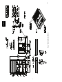
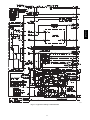
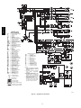
Certified Drawing for A
Project: BLDG 840
Prepared By:
05/22/2011
07:36AM
Certifie d Drawi ng
Packaged Rooftop Builder 1.29
Page 5 of 78
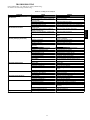
Performance Summary For A
Project: BLDG 840
Prepared By:
05/22/2011
07:36AM
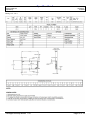
Perfor man ce Su mma ry
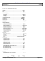
Part Number:50PG-M12-AH5--QQ
ARI EER: ....................................................................................... 12.20
IPLV:................................................................................................ 13.1
Base Unit Weight:............................................................................ 1199
Base Unit Dimensions
Unit Length: ................................................................................ 102.6
Unit Width: ................................................................................... 63.2
Unit Height: .................................................................................. 52.1
lb
in
in
in
Unit Voltage-Phase-Hertz: ......................................................... 208-3-60
Air Discharge:......................................................................... Horizontal
Fan Drive Type: .................................................................................Belt
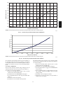
Actual Airflow: ................................................................................. 3300 CFM
Site Altitude: .......................................................................................... 0 ft
Cooling Performance
Condenser Entering Air DB: .......................................................... 95.0
Evaporator Entering Air DB: .......................................................... 80.0
Evaporator Entering Air WB: ......................................................... 67.0
Entering Air Enthalpy: ................................................................. 31.44
Evaporator Leaving Air DB: ........................................................... 56.0
Evaporator Leaving Air WB: .......................................................... 55.2
Evaporator Leaving Air Enthalpy: ................................................ 23.27
Gross Cooling Capacity: ............................................................121.28
Gross Sensible Capacity: ............................................................ 85.42
Compressor Power Input: ............................................................. 8.13
Coil Bypass Factor:..................................................................... 0.080
F
F
F
BTU/lb
F
F
BTU/lb
MBH
MBH
kW
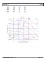
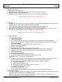
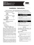
Supply Fan
External Static Pressure:............................................................... 1.60 in wg
Fan RPM: ...................................................................................... 887
Fan Power: ................................................................................... 1.78 BHP
NOTE: ............................................................ Low Range Fan Option
Electrical Data
Compressor #1 RLA: .................................................................... 17.6
Compressor #1 LRA: ..................................................................... 123
Compressor #2 RLA: .................................................................... 17.6
Compressor #2 LRA: ..................................................................... 123
Outdoor Fan Motor Qty: ..................................................................... 2
Outdoor Fan FLA (ea): .................................................................... 1.9
Indoor Fan Motor Type:................................................................. Low
Indoor Fan Motor FLA: .................................................................... 7.5
Power Supply MCA:...................................................................... 55.7
Power Supply MOCP, Fuse or HACR, U.S.A.: .................................. 70
Min. Unit Disconnect FLA: ................................................................ 59
Min. Unit Disconnect LRA: ............................................................. 315
Electrical Convenience Outlet: ...................................................... YES
Voltage Range:....................................................................... 187-253
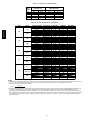
Acoustics
Sound Rating:............................................................................... 80.0 db
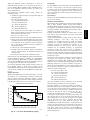
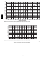
Sound Power Levels, db re 10E-12 Watts
63 Hz
Discharge
86.1
Packaged Rooftop Builder 1.29
Inlet
82.5
Outdoor
90.4
Page 6 of 78
Performance Summary For A
Project: BLDG 840
Prepared By:
05/22/2011
07:36AM
81.6
73.8
64.4
64.1
64.5
64.8
60.4
75.3
65.0
57.1
55.1
53.5
54.9
48.9
83.1
80.9
77.8
75.2
70.0
66.1
57.6
A-Weighted
73.0
64.8
80.0
in .
w g .
)
125 Hz
250 Hz
500 Hz
1000 Hz
2000 Hz
4000 Hz
8000 Hz
F a n
(
.
1
e s s u r
.
9
0
0
R
P
0
0
1
%
R
5
8
0
0
R
P
0
0
0
R
P
1
M
1
0
0
R
P
M
M
P
M
5
.
0
0
B
H
P
P r
1
Cu r v e
0
e
2
0
0
R
P
M
ic
7
.
S
0
6
0
0
R
P
M
5
0
0
R
P
M
4
0
0
R
P
M
3
0
0
R
P
M
C
S t
a t
1
0
.
5
0
.
5
0
0
.
.
7
.
B
5
0
H
3
.
0
0
B
H
P
0
B
P
0
B
H
H
P
P
0
0
1
A ir
B H P
1
0
2
.
1
.
5
0
0
B
H
P
B
H P
=
1 .
S C
-
7 8
S y s
2
f lo w
( C F M
M
a x i m
u m
t e m
C u r v e
Packaged Rooftop Builder 1.29
3
4
-
5
t h o u s a n d s )
R P M
=
1 6 0 0
R P
R a t e d
6
M
P o i
a x i
n t
m
Page 7 of 78
u m
Guide Specification for A
Project: BLDG 840
Prepared By:
05/22/2011
07:36AM
Guide Sp ecificati ons
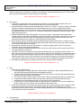
Guide Specifications
Packaged Rooftop Electric Cooling Unit with
Electric Heat Constant Volume Application
with Puron® Refrigerant
HVAC Guide Specifications
Size Range:
2 to 25 Tons, Nominal Cooling
3 to 75 kW Nominal (Electric Heating)
Carrier Model Numbers:
50PG
(NASA VAFB 840, SD-03, Item: Air Conditioning Unit)
Part 1 — General
1.01 SYSTEM DESCRIPTION
Unit is an outdoor rooftop mounted, electrically controlled heating and cooling unit utilizing fully hermetic scroll
compressors with on demand crankcase heaters for cooling duty and electric heat for heating duty. Supply air shall be
discharged downward or horizontally, as shown on contract drawings. Units shall be of ultra-high cooling efficiency
and utilize environmentally sound Puron (R-410A) refrigerant.
1.02 QUALITY ASSURANCE
A. Unit shall well exceed ASHRAE 90.1-2001 Energy Efficiency Standards. All units shall be ENERGY STAR®
qualified. On 03 to 06 sizes — SEER shall be as high as 15.0. On 06 to 16 sizes — EER shall be as high as 12.7
and on sizes 20 to 28 — EER shall be as high as 11.8.
B. Unit shall be rated in accordance with ARI Standards 210 (sizes 03-12) and 360 on all other sizes. All units shall
be designed in accordance with UL Standard 1995. Units shall be rated in accordance with ARI sound standards,
270 or 370.
C. Unit shall be designed to conform to ASHRAE 15.
D. Unit shall be UL and UL, Canada, tested and certified in accordance with ANSI Z21.47 Standards as a total
package.
E. Roof curb shall be designed to conform to NRCA Standards.
F. Insulation and adhesive shall meet NFPA 90A requirements for flame spread and smoke generation.
G. Unit casing shall be capable of withstanding 500-hour salt spray exposure per ASTM B117 (scribed specimen).
H. Unit shall be manufactured in a facility registered to ISO 9001:2000.
I. Each unit shall be subjected to a completely automated run testing on the assembly line.
1.03 DELIVERY, STORAGE, AND HANDLING
Unit shall be stored and handled per manufacturer‟s recommendations.
Part 2 — Products
2.01 EQUIPMENT (STANDARD)
A. General:
The 50PG unit shall be a factory assembled, pretested, single-piece heating and cooling unit. Contained within
the unit enclosure shall be all factory wiring, piping, controls, Puron refrigerant charge (R-410A), and special
Packaged Rooftop Builder 1.29
Page 8 of 78
Guide Specification for A
Project: BLDG 840
Prepared By:
05/22/2011
07:36AM
features required prior to field start-up. Outdoor sound ratings on sizes 03-06 shall be as low as 72 dB, on sizes
08 to 16 as low as 80 dB and on sizes 20 to 28 as low as 82 dB.
(NASA VAFB 840, SD-03, Item: Casing, Paragraph 2.1.1.4)
B. Unit Cabinet:
1. Constructed of galvanized steel, bonderized and coated with a pre-painted baked enamel finish on all
externally exposed surfaces. Internal surfaces shall be of a primer coated finish.
2. All airstream interior surfaces shall be insulated with a minimum 1/2-in. thick, 1 lb density, foilfaced, cleanable,
insulation. Insulation shall be bonded with a thermosetting resin (8 to 12% by weight nominal, phenol
formaldehyde typical), and coated with an acrylic or other material that meets the NFPA 90 flame retardance
requirements and has an „„R‟‟ Value of 3.70. Insulation shall also be encapsulated with panel design or tape
edges ensuring secure fit.
3. Cabinet panels shall be hinged with integrated non-corrosive hinges. Large hinged access panels with
multiple quarter-turn latches and handles are provided, for the filter, compressors, evaporator fan, control box
and heat section areas. Each major external hinged access panel shall be double-wall construction and
permanently attached to the rooftop unit. Panels shall also include tiebacks.
4. Return air filters shall be accessible through a dedicated hinged access panel and be on a slide out track
using standard size filters. Filter shall be standard off the shelve sizes and be the size per cabinet. Capability
for 2 or 4 inch filters shall be on all sizes.
5. Holes shall be provided in the base rails (minimum 16 gage) for rigging shackles and level travel and
movement during overhead rigging operations.
6. Fork lift slots shall be available from three sides of the unit (end and 2 sides) for 03-16 and two sides of the
unit (end and side) for other sizes.
7. Unit shall have a factory-installed internally sloped condensate drain pan, providing a minimum 3/4-in.-14
NPT connection with horizontal drain, to prevent standing water from accumulating. Pan shall be fabricated of
high impact polycarbonate material and shall slide out for cleaning and or maintenance on sizes 03-16. An
alternate vertical drain (3/4-in. NPT) connection is also available on sizes 03-16. Pan shall be fabricated of
epoxy powder coated steel for other sizes. All drain pans conform to ASHRAE 62 self-draining provisions.
8. Unit shall have standard thru-the-bottom power and control wiring connection capability.
(NASA VAFB 840, SD-03, Item: Fans, Paragraph 2.1.1.3)
C. Fans:
1. Indoor blower (evaporator fan):
a. Centrifugal supply air blower shall have rubber-isolated, cartridge type, ball bearings (50PG03-16) or
pillow-block ball bearings (50PG20-28) and adjustable belt drive.
b. Fan wheel shall be made from steel with a corrosion resistant finish. It shall be a dynamically balanced,
double-inlet type with forward-curved blades.
c. The indoor fan system (blower wheels, motors, belts, and both bearings) shall slide out for easy access.
d. Evaporator fan motors shall be continuous operation, open drip-proof. Bearings shall be sealed,
permanently lubricated ball-bearing type for longer life and lower maintenance.
e. On sizes 03 to 16, fan belt shall be located on opposite side of evaporator coil to prevent damage from
broken fan belts. On 20 to 28 sizes a fan belt catch system shall be used.
2. Condenser fans shall be of the direct-driven propeller type, with corrosion-resistant aluminum blades riveted
to corrosion-resistant steel supports. They shall be dynamically balanced and discharge air upwards.
Condenser-fan motors shall be totally enclosed thermally plated and be of a shaft down design to protect from
direct contact from harsh environments.
(NASA VAFB 840, SD-03, Item: Compressors)
D. Compressor(s):
1. Fully hermetic, scroll type with on demand crankcase heaters, internal high-pressure and temperature
Packaged Rooftop Builder 1.29
Page 9 of 78
Guide Specification for A
Project: BLDG 840
Prepared By:
05/22/2011
07:36AM
protection.
(NASA VAFB 840, SD-03, Item: Vibration Isolation, Paragraph 2.2.1)
2. Factory mounted on rubber grommets and internally spring mounted for vibration isolation.
3. Be mounted on dedicated mounting plate to ensure secure design and reduced sound levels.
(NASA VAFB 840, SD-03, Item: Cooling Coil, Paragraph 2.1.1.2)
E. Coils:
1. Standard evaporator and condenser coils shall have aluminum lanced plate fins mechanically bonded to
seamless internally grooved copper tubes with all joints brazed.
2. Dual-circuit models (08-28) shall have face-split type evaporator coil (circuit no. 1 on bottom).
3. Evaporator and condenser coils shall be single slab, single pass design to facilitate easy coil cleaning.
Composite coils or coils that require unit top panels removed shall be unacceptable.
4. Coils shall be leak tested at 170 psig and pressure tested at 1875 psig.
5. Optional Coils:
a. Optional pre-coated aluminum-fin coils shall have a durable epoxy-phenolic coating to provide protection
in mildly corrosive coastal environments. Coating shall be applied to the aluminum fin stock prior to the fin
stamping process to create an inert barrier between the aluminum fin and copper tube. Epoxy-phenolic
barrier shall minimize galvanic action between dissimilar metals.
b. Optional copper-fin coils shall be constructed of copper fins mechanically bonded to copper tubes and
copper tube sheets. Galvanized steel tube sheets shall not be acceptable. A polymer strip shall prevent
coil assembly from contacting the sheet metal coil pan to minimize potential for galvanic corrosion
between coil and pan. All copper construction shall provide protection in moderate coastal environments.
c. Optional E-Coated aluminum-fin coils shall have a flexible epoxy polymer coating uniformly applied to all
coil surface areas without material bridging between fins. Coating process shall ensure complete coil
encapsulation. Color shall be high gloss black with gloss — 60 deg of 65 to 90% per ASTM D523-89.
Uniform dry film thickness from 0.8 to 1.2 mil on all surface areas including fin edges. Superior hardness
characteristics of 2H per ASTM D3363-92A and crosshatch adhesion of 4B-5B per ASTM D3359-93.
Impact resistance shall be up to 160 in./lb (ASTM D2794-93). Humidity and water immersion resistance
shall be up to minimum 1000 and 250 hours respectively (ASTM D2247-92 and ASTM D870-92).
Corrosion durability shall be confirmed through testing to be no less than 1000 hours salt spray per ASTM
B117-90. Coil construction shall be aluminum fins mechanically bonded to copper tubes. E-Coated
aluminum-fin coils shall provide protection in industrial and industrial and coastal combined environments.
d. Optional E-Coated copper-fin coils shall have a flexible epoxy polymer coating uniformly applied to all coil
surface areas without material bridging between fins. Coating process shall ensure complete coil
encapsulation. Color shall be high gloss black with gloss — 60 deg of 65 to 90% per ASTM D523-89.
Uniform dry film thickness from 0.8 to 1.2 mil on all surface areas including fin edges. Superior hardness
characteristics of 2H per ASTM D3363-92A and cross-hatch adhesion of 4B-5B per ASTM D3359-93.
Impact resistance shall be up to 160 in./lb (ASTM D2794-93). Humidity and water immersion resistance
shall be up to minimum 1000 and 250 hours respectively (ASTM D2247-92 and ASTM D870-92).
Corrosion durability shall be confirmed through testing to be no less than 1000 hours salt spray per ASTM
B117-90. Coil construction shall be copper fins mechanically bonded to copper tubes with copper tube
sheets. Galvanized steel tube sheets shall not be acceptable. A polymer strip shall prevent coil assembly
from contacting sheet metal coil pan to maintain coating integrity and minimize corrosion potential
between coil and pan. E-Coated copper-fin coils shall provide protection in severe coastal environments.
F. Heating Section:
1. Heater element open coil resistance wire, nickel-chrome alloy, 0.29 inches inside diameter, strung through
ceramic insulators mounted on metal frame. Coil ends are staked and welded to terminal screw slots.
2. Heater assemblies are provided with integral fusing for protection of internal heater circuits not exceeding 48
amps each.
3. Auto reset thermo limit controls, magnetic heater contactors (24 v coil) and terminal block all mounted in
electric heater control box (minimum 18 ga galvanized steel) attached to end of heater assembly.
Packaged Rooftop Builder 1.29
Page 10 of 78
Guide Specification for A
Project: BLDG 840
Prepared By:
05/22/2011
07:36AM
G. Refrigerant Components:
Each refrigerant circuit shall include:
1. Balanced port thermostatic expansion valve (TXV) with removable power element.
2. Refrigerant filter driers with pressure ports.
3. Refrigerant pressure gage port and connections on suction, discharge, and liquid lines.
(NASA VAFB 840, SD-03, Item: Filters, Paragraph 2.1.1.6)
H. Filter Section:
1. Standard filter section shall consist of factory-installed 2-in. thick disposable fiberglass filters and shall be on a
dedicated slide-out track to easily facilitate access and replacement.
2. Filter section shall use standard size filters and be a common size within cabinet sizes.
3. Optional MERV-8 pleated filters of commercially available sizes shall be available.
4. Standard 2-in. filter rack shall be field convertible to 4-in. by removing a spacer rack on 03-16 sizes. A 4-in.
filter capability shall be available as factory-installed option on the other sizes.
(NASA VAFB 840, SD-03, Item: Controls, Paragraph 2.1.1.5)
I.
J.
Controls and Safeties:
1. Unit ComfortLink™ controls:
a. Scrolling Marquee display.
b. CCN network capable.
c. Unit control with standard suction pressure transducers and condensing temperature thermistors.
d. Shall provide a 5° F temperature difference between cooling and heating set points to meet ASHRAE
90.1 Energy Standard.
e. Shall provide and display a current alarm list and an alarm history list.
f. Automatic compressor redundancy.
g. Service run test capability.
h. Shall accept input from a CO2 sensor (both indoor and outdoor).
i. Configurable alarm light shall be provided which activates when certain types of alarms occur.
j. Compressor minimum run time (3 minutes) and minimum off time (5 minutes) are provided.
k. Service diagnostic mode.
l. Economizer control (optional).
m. Multiple capacity stages (on size 08-28 units only).
n. Unit shall be complete with self-contained low-voltage control circuit.
o. Unit shall have 0° F low ambient cooling operation.
2. Safeties:
a. Unit shall incorporate a solid-state compressor lockout which provides optional reset capability at the
space thermostat, should any of the following safety devices trip and shut off compressor:
1) Compressor lockout protection provided for either internal or external overload.
2) Low-pressure protection.
3) Freeze protection (evaporator coil).
4) High-pressure protection (high pressure switch or internal).
5) Compressor reverse rotation protection.
6) Loss of charge protection.
7) Start assist on single-phase units.
b. Supply-air sensor shall be located in the unit and detect both heating and cooling operation.
Operating Characteristics:
1. Unit shall be capable of starting and running at 125 F ambient outdoor temperature per maximum load criteria
of ARI Standard 210 (sizes 03-12) and 360 (sizes 16-28).
2. Unit with ComfortLink controls will operate in cooling down to an outdoor ambient temperature of 0° F.
Electro-mechanical controls shall operate down to 40 F.
Packaged Rooftop Builder 1.29
Page 11 of 78
Guide Specification for A
Project: BLDG 840
Prepared By:
05/22/2011
07:36AM
3. Unit shall be provided with fan time delay to prevent cold air delivery in heating mode.
K. Electrical Requirements:
All unit power wiring shall enter unit cabinet at a single location — side or bottom.
NOTE: On 208/230 v units using 75-kW heaters, separate wiring is required.
L. Motors:
1. Compressor motors shall be cooled by refrigerant gas passing through motor windings and shall have line
break thermal and current overload protection.
2. Evaporator-fan motor shall have permanently lubricated, sealed bearings and inherent automatic- reset
thermal overload protection or manual reset calibrated circuit breakers. Evaporator motors are designed
specifically for Carrier and do not have conventional horsepower (hp) ratings listed on the motor nameplate.
Motors are designed and qualified in the “air-over” location downstream of the cooling coil and carry a
maximum continuous bhp rating that is the maximum application bhp rating for the motor; no “safety factors”
above that rating may be applied.
3. All evaporator fan motors 5 hp and larger shall meet the minimum efficiency requirements as established by
the Energy Policy Act of 1992 (EPACT), effective October 24, 1997.
4. Totally enclosed condenser-fan motor shall have permanently lubricated, sealed bearings, and inherent
automatic-reset thermal overload protection.
M. Special Features:
Certain features are not applicable when the features designed * are specified. For assistance in amending the
specifications, contact your local Carrier Sales Office.
* 1. Full Perimeter Roof Curbs (Horizontal and Vertical):
a. Formed of 14-gage galvanized steel with wood nailer strip and shall be capable of supporting entire unit
weight. Shall be interlocking design.
b. Permits installing and securing ductwork to curb prior to mounting unit on the curb. Field assembly
required.
c. Shall be available in both 14-in. and 24-in. height.
* 2. Adapter Roof Curb:
Shall be available for fit up on previously installed Carrier DJ, TJ, LJ, TF, HJ, TM roof curbs (sizes 03-14).
* 3. Integrated Economizer:
a. Tilt-out economizer (16-28 slide out) shall be furnished and installed complete with outside-air dampers
and controls.
b. Low-leakage, opposing, gear-driven dampers with UL approved gears.
c. Capable of introducing up to 100% outdoor air for minimum ventilation as well as free cooling.
d. Damper actuator shall be electronic 4 to 20 mA or 2 to 10 vdc fully modulating design.
e. Economizer outdoor hood shall be prepainted and fully assembled on sizes 03-16. Economizer outdoor
hood requires field assembly on other sizes.
f. Economizer shall be available for both field or factory installation.
* 4. Two-Position Motorized Outdoor Air Damper:
a. The damper shall admit up to 50% outdoor air. Spring return damper closes when unit is off.
b. The package shall include a multiple-blade damper and motor.
c. Shall be available as factory-installed option and field-installed accessory.
* 5. Manual Outdoor Air Damper:
a. The damper shall admit up to 33% outdoor air.
b. Shall include hood, damper plate, and screen (sizes 03-16) or cleanable aluminum filter (sizes 20-28).
c. Shall be available as factory-installed option and field-installed accessory.
* 6. Barometric Relief Damper Package:
a. Package shall include damper, seals, hardware, and hoods to relieve excess internal pressure.
b. Integrated barometric relief capabilities on economizer shall be available on sizes 03-16.
c. Damper shall close due to gravity upon unit shutdown.
* 7. Power Exhaust:
a. For 03-16 sizes, package shall include two (2) propeller exhaust fans, 0.25 Hp (03-07)/0.5 Hp (08-16)
208-230 v, 460 v direct-drive motor on each, and damper for units with economizer to control
overpressurization of building. Single-stage control.
b. For 20-28 sizes, package shall include two (2) centrifugal exhaust fans, 1 Hp 208-230, 460 v (factorywired for 460 v) three-speed direct drive motor on each, and damper for units with economizer to control
over-pressurization of building. Two-stage exhaust capability through ComfortLink™ control shall be
Packaged Rooftop Builder 1.29
Page 12 of 78
Guide Specification for A
Project: BLDG 840
Prepared By:
05/22/2011
07:36AM
available.
c. Power exhaust shall fit on both vertical and horizontal configured unit.
d. Power exhaust shall be available for both field or factory installation.
8. Single Enthalpy Sensor:
The enthalpy sensor shall provide economizer control based on outdoor air enthalpy. The economizer control
shall include logic to calculate the wet bulb and dry bulb temperatures of the outdoor air.
9. Differential Enthalpy Sensor:
a. For use with economizer only.
b. Capable of comparing heat content (temperature and humidity) of outdoor air and indoor air and
controlling economizer cut-in point at the most economical level.
10. Convenience Outlet:
a. Optional factory-installed powered convenience outlet shall be internally mounted with an externally
accessible 115-v, 2 plug female receptacle with hinged cover. Shall include 15 amp GFI with independent
fuse protection and service receptacle disconnect. The convenience outlet is powered from the line side
of the disconnect or circuit breaker with a factory-installed step down transformer, therefore it will not be
affected by the position of the disconnect or circuit breaker.
b. Optional factory-installed non-powered convenience outlet shall be internally mounted with an externally
accessible 115-v, 2 plug female receptacles with hinged cover. There is no step-down transformer
installed from the factory.
*11. HACR Circuit Breaker:
Shall be factory-installed, internally mounted, NEC and UL approved. HACR breaker shall provide unit power
shutoff. Shall be accessible from outside the unit and shall provide power off lockout capability.
12. CO2 Sensor:
The duct-mounted or wall-mounted CO2 sensor shall have the ability to monitor CO2 levels and relay
information to the controller. The controller will use CO2 level information to modulate the economizer and
provide demand control ventilation. The sensor shall be available as field or factory-installed.
13. Return Air/Supply Air Smoke Detector:
The smoke detector shall send input to the controller to shut down the unit in case smoke is detected. The
smoke detector shall be factory installed in the return air section or shall be available as a field-installed
accessory.
14. Filter Status:
The filter status switch shall be a pressure switch and will indicate a dirty filter. The switch shall be available
as field or factory-installed.
15. Fan Status:
The fan status switch shall be a pressure switch and will indicate indoor fan operation. The switch shall be
available as field or factory-installed.
*16. MERV-8 Pleated Return Air Filters:
The filters shall be MERV-8 efficient. The filters shall be 2-in., pleated filters.
17. Four-in. Return Air Filter Capability:
a. The unit shall be capable of accepting field-supplied 4-in. filters by removing a spacer rack on 03-16 sizes
standard units.
b. The unit with factory-installed option of 4-in. filter capability (20-28) shall be capable of accepting fieldsupplied 4-in. filters by removal of the factory-supplied 2-in. filters and filter retainer.
*18. Low Range Fan Performance Motor/Drive:
This motor/drive option shall provide low range motor and drive capability to enhance evaporator fan
performance.
*19. Mid-Low Fan Performance Motor/Drive (16-28 sizes):
This motor/drive shall provide low to medium motor and drive capability to enhance evaporator fan
performance.
*20. Mid-High Fan Performance Motor/Drive (20-28 sizes):
This motor/drive option shall provide medium to high motor and drive capability to enhance evaporator fan
performance.
*21. High Fan Performance Motor/Drive:
This motor/drive offering shall provide high range motor and drive capability to enhance evaporator fan
performance.
22. Hail Guard, Condenser Coil Grille:
Packaged Rooftop Builder 1.29
Page 13 of 78
Guide Specification for A
Project: BLDG 840
Prepared By:
05/22/2011
07:36AM
Shall protect the condenser coil from hail, flying debris, and damage by large objects without increasing unit
clearances.
23. Horizontal Kit:
a. Horizontal kit shall contain all the necessary hardware to convert a vertical airflow unit to a horizontal
airflow unit (16-28 sizes).
b. The unit shall also be available as a horizontal airflow unit directly from the factory.
24. Phase Loss Protection (3 phase units only):
Shall provide unit shutdown when an electrical phase loss is detected — automatic reset type.
25. Roof Curb Burglar Bar:
Shall be 1/2-in. diameter rod with 9-in. on center design grid pattern. Shall mount in roof curb openings.
*26. Electronic Programmable Thermostat:
Capable of using deluxe full-featured electronic thermostat.
*27. Thermostats and Subbases:
To provide staged heating and cooling in addition to automatic (or manual) changeover and fan control.
*28. Electric Resistance Heater Package:
a. Fully assembled for installation. The packages are designed in accordance with UL safety standards
1995 and listed by ETL. Heater construction approved by UL 5306.
b. Single point kits available for each heater when required (sizes 03-14).
29. Unit-Mounted, Non-Fused Disconnect Switch:
Switch shall be factory-installed, internally mounted. NEC and UL approved non-fused switch shall provide
unit power shutoff. Switch shall be accessible from outside the unit and shall provide power off lockout
capability.
*30. Humidi-MiZer™ Adaptive Dehumidification System:
a. The Humidi-MiZer dehumidification system shall be factory-installed in the 50PG03-28 rooftop units, and
shall provide greater dehumidification of the occupied space by two modes of dehumidification operations
beside its normal design cooling mode:
1) Subcooling mode further subcools the hot liquid refrigerant leaving the condenser coil when both
temperature and humidity in the space are not satisfied.
2) Hot gas reheat mode shall mix a portion of the hot gas from the discharge of the compressor with the
hot liquid refrigerant leaving the condenser coil to create a two-phase heat transfer in the system,
resulting in a neutral leaving-air temperature when only humidity in the space is not satisfied.
b. The system shall consist of a subcooling/reheat dehumidification coil located downstream of the standard
evaporator coil. This dehumidification coil is a single-row coil on 50PG03-16 units. This dehumidification
coil is a two-row coil on 50PG20-28 units.
c. The system shall include crankcase heater(s) for the scroll compressor(s).
d. The system shall include a low outdoor air temperature switch to lock out both subcooling and hot gas
reheat mode when the outdoor-air temperature is below 40 F.
e. The system shall include a Motormaster® low ambient control to ensure the normal design cooling mode
capable of down to 0° F low ambient operation.
f. The system shall include a low-pressure switch on the suction line to ensure low pressure start-up of hot
gas reheat mode at lower outdoor temperature condition.
g. The system operation may be controlled by a field-installed, wall-mounted humidistat. The
dehumidification circuit will then operate only when needed. Field connections for the humidistat are
made in the low-voltage compartment of the unit control box. The sensor can be set for any level between
55% and 80% relative humidity.
h. The system shall include a thermostatic expansion valve (TXV) to ensure a positive superheat condition.
i. For units with two or three compressors (sizes 08-28), depending on the conditions required to maintain
the space set points, one or all the compressors can operate in subcooling mode, one compressor could
operate in subcooling mode while the other(s) operate in hot gas reheat mode, or one or all the
compressors can operate in hot gas reheat mode.
Packaged Rooftop Builder 1.29
Page 14 of 78
Unit Feature Sheet for A
Project: BLDG 840
Prepared By:
05/22/2011
07:36AM
Unit Fe atu re She et
- 50PG
PACKAGED ROOFTOP ELECTRIC COOLING UNITS
2, 3, 4, 5, 6, 7.5, 8.5, 10, 12.5, 15, 18, 20, 25 TONS
STANDARD FEATURES INCLUDE:
Puron (R-410A) HFC refrigerant
SEER's up to 15.0, EER's up to 12.7, IPLV's up to 13.3
ARI certified outdoor sound levels as low as 72 db
Scroll compressors with crankcase heaters, internal line break overload
and high-pressure protection
Single compressors, single stage cooling on 03 - 07 models
Dual compressors, dual stage cooling on 08 - 28 models
TXV refrigerant metering system on each circuit
High Pressure, Low Pressure/Loss of charge, and Freeze protection.
Solid core liquid line filter drier on each circuit.
Ambient cooling operation from 0 F up to 125 F (DDC controls) and from
40 F up to 125 F (Electro-mechanical controls)
Foil faced insulation throughout entire unit
Pre-painted exterior panels and primer-coated interior panels tested to
500 hours ASTM B117 (scribed specimen)salt spray protection
Internally sloped condensate pan conforms to ASHRAE 62 standards
High performance belt drive indoor fan assemblies
Internally protected, shaft down totally enclosed condenser motors
2 inch filter standard, field convertible to 4 inch capability
24 volt control system with resettable circuit breakers
Models 50PG 03-28 are E NERGY S TAR qualified
MAINTENANCE FEATURES:
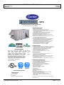
CENTURION SERIES
50PG units are single piece packaged ultra high efficiency
electric cooling with optional electric heat rooftops.
They
provide
industry
leading operating
efficiencies,
ease of
maintenance, ease of installation, and reliability. Units come
pre-wired
and
pre-charged
with
PURON
(R401A)
environmentally friendly refrigerant at the factory. Units are
factory tested in both heating and cooling modes. Units are
rated in accordance with ARI Standard 210 (03-06 sizes) and
360 (07-28 sizes). Tested in accordance with UL Standard
1995 and listed with UL and UL Canada.
Approved and certified by:
Sizes 04-06
Certified to ISO 9001:2000
STANDARD WARRANTY:
5-year electric heater
5-year compressor
1-year parts
Many optional upgrades also available
Packaged Rooftop Builder 1.29
Sizes 07-28
Single slab, single pass evaporator and condenser coils with dual side
access panels facilitate easy cleaning for maintained high efficiencies
Hinged access doors with, quick turn latches and door retainers
Slide out Indoor fan assembly for added service convenience
Dedicated, fully insulated compressor compartment
Slide out condensate pan (03-16 models)
Permanently lubricated evaporator and condenser motors
INSTALLATION FEATURES:
Thru the bottom and side electrical connection capabilities
Weather tight thru the bottom access plate
Single point electrical and gas connections
Return and supply duct fits between 24" on center joist (03-12 models)
Field convertible from vertical to horizontal airflow (03-16 models)
Single piece outdoor air hoods
Full perimeter baserail with built-in rigging adapters and fork truck slots
FACTORY INSTALLED OPTIONS INCLUDE:
ComfortLINK Direct Digital Controls (DDC)
Exclusive Humidi-MiZer adaptive dehumidification system
Exclusive EnergyX Energy Recovery module
Supply and/or return air smoke detectors
Powered or non-powered 115 volt convenience outlet
Non-fused disconnect switch or circuit breaker (HACR)
Dry bulb or enthalpy economizer
Manual outdoor air damper
Two position motorized outdoor damper
Barometric relief damper
Power Exhaust
Condenser coil guard
MERV-8 Pleated filter upgrade
CO2 sensor
Fan status and filter status switches
Side-by-side horizontal ducts (sizes 20-28. Std all other models)
High static indoor fan and drive systems
Phase loss and compressor reverse rotation protection
Corrosion resistant options for evaporator and condenser coils
Electric heaters
For a complete list of options and accessories refer to the Product Data
Catalog for this unit.
Page 15 of 78
Spec Sheet for A
Project: BLDG 840
Prepared By:
05/22/2011
07:36AM
Spec Shee t
Economizer Hood
Packaged Rooftop Builder 1.29
Page 16 of 78
Spec Sheet for A
Project: BLDG 840
Prepared By:
05/22/2011
07:36AM
Economizer Dampers
Packaged Rooftop Builder 1.29
Page 17 of 78
Spec Sheet for A
Project: BLDG 840
Prepared By:
05/22/2011
07:36AM
Heating Coil – HC-3
Packaged Rooftop Builder 1.29
Page 18 of 78
Spec Sheet for A
Project: BLDG 840
Prepared By:
05/22/2011
07:36AM
Unit A
Installation Manuals
(NASA VAFB 840, SD-3, Item: Installation Manual, Paragraph 3.1)
Packaged Rooftop Builder 1.29
Page 19 of 78
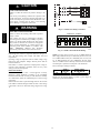
50PG08---16
Single Package Rooftop units
Electric Cooling with PURONR (R---410A) Refrigerant
and Electromechanical Controls
Installation Instructions
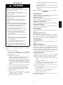
TABLE OF CONTENTS
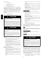
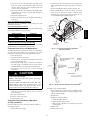
Understand the signal words DANGER, WARNING, and
CAUTION. These words are used with the safety--alert symbol.
DANGER identifies the most serious hazards which will result in
severe personal injury or death. WARNING signifies a hazard
which could result in personal injury or death. CAUTION is used
to identify unsafe practices which may result in minor personal
injury or product and property damage. NOTE is used to
highlight suggestions which will result in enhanced installation,
reliability, or operation.
SAFETY CONSIDERATIONS . . . . . . . . . . . . . . . . . . . . . . . . 1
INSTALLATION . . . . . . . . . . . . . . . . . . . . . . . . . . . . . . . . . . . 2
Step 1 -- Plan for Unit Location . . . . . . . . . . . . . . . . . . . . . 2
Step 2 -- Provide Unit Support . . . . . . . . . . . . . . . . . . . . . . 2
Step 3 -- Rig and Place Unit . . . . . . . . . . . . . . . . . . . . . . . . 2
Step 4 -- Field Fabricate Ductwork . . . . . . . . . . . . . . . . . . 11
!
Step 5 -- Make Unit Duct Connections . . . . . . . . . . . . . . . 11
Step 6 -- Install External Trap for Condensate Drain . . . . . 11
WARNING
Step 7 -- Make Electrical Connections . . . . . . . . . . . . . . . . 12
ELECTRICAL SHOCK HAZARD
Step 8 -- Optional EconoMi$er IV . . . . . . . . . . . . . . . . . . 29
Failure to follow this warning could cause personal
injury or death.
Step 9 -- Install All Accessories . . . . . . . . . . . . . . . . . . . . . 36
Before performing service or maintenance operations
on unit, turn off main power switch to unit and install
lockout tag. Ensure electrical service to rooftop unit
agrees with voltage and amperage listed on the unit
rating plate.
PRE--START--UP . . . . . . . . . . . . . . . . . . . . . . . . . . . . . . . . . . 37
START--UP . . . . . . . . . . . . . . . . . . . . . . . . . . . . . . . . . . . . . . . 37
SERVICE . . . . . . . . . . . . . . . . . . . . . . . . . . . . . . . . . . . . . . . . 47
TROUBLESHOOTING . . . . . . . . . . . . . . . . . . . . . . . . . . . . . 55
UNIT START--UP CHECKLIST . . . . . . . . . . . . . . . . . . . . . . 58
!
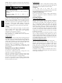
SAFETY CONSIDERATIONS
WARNING
Installation and servicing of air-conditioning equipment can be
hazardous due to system pressure and electrical components.
Only trained and qualified service personnel should install, repair,
or service air-conditioning equipment.
Untrained personnel can perform the basic maintenance functions
of cleaning coils and filters and replacing filters. All other
operations should be performed by trained service personnel.
When working on air-conditioning equipment, observe
precautions in the literature, tags and labels attached to the unit,
and other safety precautions that may apply.
Follow all safety codes. Wear safety glasses and work gloves.
Recognize safety information. This is the safety--alert symbol
UNIT OPERATION AND SAFETY HAZARD
. When you see this symbol on the unit and in instructions or
manuals, be alert to the potential for personal injury.
Failure to follow this warning could result in personal
injury, death and/or property damage.
Failure to follow this warning could cause personal
injury, death and/or equipment damage.
Puron (R--410a) refrigerant systems operate at higher
pressures than standard R--22 systems. Do not use R--22
service equipment or components on Puron refrigerant
equipment.
!
WARNING
FIRE, EXPLOSION HAZARD
1. Improper installation, adjustment, alteration, service,
or maintenance can cause property damage, personal
injury, or loss of life. Refer to the User’s Information
Manual provided with this unit for more details.
2. Do not store or use gasoline or other flammable
vapors and liquids in the vicinity of this or any other
appliance.
1
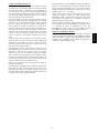
IMPORTANT: Units have high ambient operating limits. If
limits are exceeded, the units will automatically lock the
compressor out of operation. Manual reset will be required to
restart the compressor.
Installation and servicing of air-conditioning equipment can be
hazardous due to system pressure and electrical components.
Only trained and qualified service personnel should install, repair,
or service air-conditioning equipment.
IMPORTANT: The gasketing of the unit to the roof curb is
critical for a watertight seal. Install gasket with the roof curb as
shown in Fig. 1, 2 and 5. Improperly applied gasket can also
result in air leaks and poor unit performance. Do not slide unit to
position on roof curb.
Alternate Unit Support
When a curb cannot be used, install unit on a noncombustible
surface. Support unit with sleepers, using unit curb support area.
If sleepers cannot be used, support long sides of unit with a
minimum of 3 equally spaced 4-in. x 4-in. pads on each side.
INSTALLATION
50PG08---16
Step 1 —Plan for Unit Location
Step 3 —Rig and Place Unit
Select a location the unit and its support system (curb or other)
that provides minimum clearances required for safety, unit
performance and service access below, around and above unit as
specified in unit drawings. Consider also the effect of adjacent
units.
Do not install unit in an indoor location. Do not locate air inlets
near exhaust vents or other sources of contaminated air. Although
unit is weatherproof, guard against water from higher level runoff
and overhangs.
Select a unit mounting system that provides adequate height to
allow installation of condensate trap per requirements. Refer to
Step 6 — Install External Trap for Condensate Drain for
required trap dimensions.
Roof Mount
Check building codes for weight distribution requirements. Unit
operating weight is shown in Tables 1 and 2.
Inspect unit for transportation damage. See Tables 1 and 2 for
physical data. File any claim with transportation agency.
!
WARNING
PROPERTY DAMAGE HAZARD
Failure to follow this warning could result in personal
injury, death and property damage.
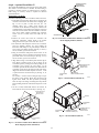
All panels must be in place when rigging and lifting.
Do not drop unit; keep upright. Use wooden top skid or spreader
bars over unit to prevent sling or cable damage. Rollers may be
used to move unit across a roof. Level by using unit rail as a
reference; leveling tolerance is ± 1/16 in. per linear ft in any
direction. Unit rigging weight is shown in Fig. 5.
Rigging holes are provided in the unit base rails as shown in Fig.
5. Refer to rigging instructions on unit. See Fig. 3 and 4 for panel
and filter locations.
After unit is in position, remove top crating and polyethylene sheet.
Step 2 —Provide Unit Support
Roof Curb
Assemble or install accessory roof curb in accordance with
instructions shipped with this accessory. See Fig. 1A and 1B.
Install insulation, cant strips, roofing, and counter flashing as
shown. Ductwork can be installed to roof curb before unit is set
in place. Ductwork must be attached to curb and not to the unit.
Curb must be level. This is necessary to permit unit drain to
function properly. Unit leveling tolerance is ± 1/16 in. per linear ft
in any direction. Refer to Accessory Roof Curb Installation
Instructions for additional information as required. When
accessory roof curb is used, unit may be installed on class A, B,
or C roof covering material. Carrier roof curb accessories are for
flat roofs or slab mounting.
2
3
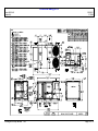
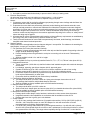
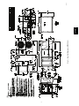
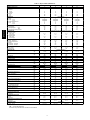
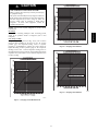
Fig. 1 --- Roof Curb Details (50PG08--14)
50PG08 ---16
C06312
4
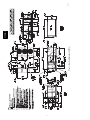
Fig. 2 --- Roof Curb Details (50PG16)
50PG08 ---16
C06306
5
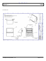
Fig. 3 --- Base Unit Dimensions (50PG08--14)
50PG08 ---16
C06313
6
Fig. 4 --- Base Unit Dimensions (50PG16)
50PG08 ---16
C06314
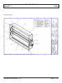
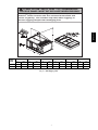
CAUTION - NOTICE TO RIGGERS:
ACCESS PANEL MUST BE IN PLACE WHEN RIGGING.
50PG08---16
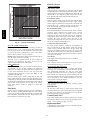
Hook rigging shackles through holes in base rail, as shown in
Detail A. Holes in base rails are centered around the unit
center of gravity. Use wooden top skid, when rigging, to
prevent rigging straps from damaging unit.
UNIT
SIZE
A
B
C
D
E
MAX. WEIGHT
in.
mm
in.
mm
in.
mm
in.
mm
in.
mm
lb
kg
08---14
90.4
2296
36--- 54
914--- 1371
52.4
1331
48.0
1219
26.5
668
1572
713
16
100.4
2550
36--- 54
914--- 1371
52.4
1331
51.0
1245
35.0
889
1895
861
Fig. 5 --- 50PG Rigging Label
7
C06253
50PG08---16
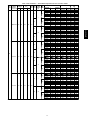
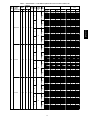
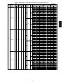
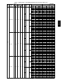
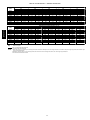
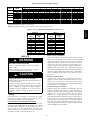
Table 1—Physical Data (50PG08-14)
BASE UNIT 50PG
NOMINAL CAPACITY (Tons)
OPERATING WEIGHT (lb)
Unit*
Economizer
Vertical
Horizontal
Roof Curb
14-in.
24-in.
COMPRESSOR
Quantity
Oil Type
Sys A
Sys B
Number of Refrigerant Circuits
Oil (oz)
Sys A
Sys B
REFRIGERANT TYPE
Expansion Device
Operating Charge (lb)
Sys A
Sys B
Operating Charge Total All Systems (lb)
CONDENSER COIL
Condenser A (Outer)
Rows...Fins/in.
Face Area (sq ft)
Condenser B (Inner)
Rows...Fins/in.
Face Area (sq ft)
CONDENSER FAN
Quantity…Diameter (in.)
Nominal Cfm (Total, all fans)
Motor Hp
Nominal Rpm — High Speed
Nominal Rpm — Low Speed
EVAPORATOR COIL
Rows…Fins/in.
Face Area (sq ft)
EVAPORATOR FAN
Quantity…Size (in.)
Type Drive
Nominal Cfm
Maximum Continuous Bhp
Motor Nominal Rpm
Motor Frame Size
Fan Rpm Range
Motor Bearing Type
Maximum Fan Rpm
Motor Pulley Pitch Diameter Range (in.)
Fan Pulley Pitch Diameter
Nominal Motor Shaft Diameter (in.)
Belt…Pitch Length (in.)
Belt…Type
Pulley Center Line Distance Min. (in.)
Pulley Center Line Distance Max. (in.)
Speed Change per Full Turn of
Movable Pulley Flange (rpm)
Movable Pulley Maximum Full
Turns from Closed Position
Factory Pulley Setting (rpm)
08
09
12
14
7.5
8.5
10
12.5
1098
1105
1199
1310
57
59
57
59
57
59
57
59
180
268
180
268
180
268
180
268
2
Copeland 3MA
Copeland 3MA
2
42
42
TXV
11.8
11.8
23.5
Low
High
Low
High
Low
High
Low
High
Low
High
Low
High
Low
High
Low
High
Low
High
Low
High
Low
High
Low
High
Fan Shaft Diameter at Pulley (in.)
HIGH-PRESSURE SWITCH (psig)
Cutout
Reset (Auto.)
LOW-PRESSURE SWITCH (psig)
Cutout
Reset (Auto.)
FREEZE PROTECTION THERMOSTAT (F)
Cutout
Reset (Auto.)
RETURN-AIR FILTERS
Quantity…Size (in.)
TXV
17.2
17.2
34.4
2…17
17.4
2…17
17.4
3…17
17.4
2...17
17.4
2...17
17.4
2...17
17.4
3...17
17.4
Propeller
2...24
2...24
7204
8341
1/
1/
4
3
1100
1100
900
900
Enhanced Copper Tubes, Aluminum Double-Wavy Fins, Face Split
3…15
4…15
14.9
14.9
Centrifugal Type, Belt Drive
1...15 x 15
1...15 x 15
1...15 x 15
1...15 x 15
Belt
Belt
Belt
Belt
3400
4000
2.40
3.10
3.70
3.70
1725
1725
56Y
56Y
56Y
56Y
568-771
690-893
812-1015
852-1055
Ball
Ball
1600
1600
2.8-3.8
3.4-4.4
4.0-5.0
4.6-5.6
8.5
8.5
8.5
8.5
5/
7/
8
8
7/
7/
8
8
63.3
63.3
65.3
65.3
AX
AX
AX
AX
21.0
21.0
21.0
21.0
23.4
23.4
23.4
23.4
41
41
41
41
5
5
5
5
568
690
812
852
1
1
3…15
14.9
Low
High
2
Copeland 3MA
Copeland 3MA
2
56
56
2…17
17.4
2...24
7204
1/
4
1100
900
Low
High
Low
High
Fully Hermetic Scroll
2
2
Copeland 3MA
Copeland 3MA
Copeland 3MA
Copeland 3MA
2
2
42
66
42
66
R-410A (Puron® Refrigerant)
TXV
TXV
11.3
13.7
11.3
13.7
22.6
27.4
Enhanced Copper Tubes, Aluminum Lanced Fins, Face Split
1...15 x 15
1...15 x 15
Belt
Belt
3000
2.40
3.10
1725
56Y
56Y
568-771
812-1015
Ball
1600
2.8-3.8
4.0-5.0
8.5
8.5
5/
8
7/
8
63.3
65.3
AX
AX
21.0
21.0
23.4
23.4
41
41
5
5
568
812
1
2...24
7300
1/
3
1100
900
4…15
14.9
1...15 x 15
1...15 x 15
Belt
Belt
5000
3.70
5.25
1725
56Y
56Y
690-893
852-1055
Ball
1600
3.4-4.4
4.6-5.6
8.5
8.5
7/
8
7/
8
63.3
65.3
AX
AX
21.0
21.0
23.4
23.4
41
41
5
5
690
852
1
660 ± 10
505 ± 20
660 ± 10
505 ± 20
660 ± 10
505 ± 20
660 ± 10
505 ± 20
40 ± 7
80 ± 7
40 ± 7
80 ± 7
40 ± 7
80 ± 7
40 ± 7
80 ± 7
30 ± 5
45 ± 5
30 ± 5
45 ± 5
30 ± 5
45 ± 5
30 ± 5
45 ± 5
4...20 x 25 x 2
4...20 x 25 x 2
4...20 x 25 x 2
4...20 x 25 x 2
LEGEND
TXV — Thermostatic Expansion
*Aluminum evaporator/aluminum condenser coil fin material
8
Throwaway Type
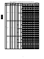
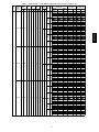
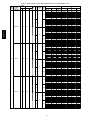
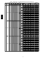
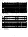
Table 2—Physical Data (50PG16)
Type Drive
Nominal Cfm
Maximum Continuous Bhp
Motor Frame Size
Fan Rpm Range
Motor Bearing Type
Motor Pulley Pitch Diameter Min (in.)
Motor Pulley PItch Diameter Max (in.)
Fan Pulley Pitch Diameter
Nominal Motor Shaft Diameter (in.)
Belt…Pitch Length (in.)
16
15.0
1771
149
64
240
360
Fully Hermetic Scroll
3
Copeland 3MA
Copeland 3MA
Copeland 3MA
3
66
66
66
R--410A (Puron® Refrigerant)
TXV
13.5
15.0
15.0
43.5
18.8
16.7
18.8
54.3
Enhanced Copper Tubes, Aluminum Lanced Fins, Face Split
2…17
26.6
2...17
30.2
Enhanced Copper Tubes, Aluminum Lanced Fins
1...17
22.2
Propeller
3...24
12,500
1/ 3
1100
Enhanced Copper Tubes, Aluminum Double--Wavy Fins, Face Split 3…15
22.2
Centrifugal Type, Belt Drive
1...15 x 15, 1...12 x 12
1...15 x 15, 1...12 x 12
1...15 x 15, 1...12 x 12
Belt
Belt
Belt
6000
3.7
5.25
7.5
56
56
S213T
710--879
872--1066
1066--1260
Ball
4.2
4.2
5.2
5.2
5.2
6.2
10.2
8.5
8.5
7/8
7/8
13/8
49.3
47.8
43.8
Low
Mid--Low
High
Low
Mid--Low
High
Low
Mid--Low
High
Low
Mid--Low
HIgh
Low
Mid--Low
High
Low
Mid--Low
High
Low
Mid--Low
High
Low
Mid--Low
High
Low
Mid--Low
High
Low
Mid--Low
High
9
50PG08---16
BASE UNIT 50PG
NOMINAL CAPACITY (Tons)
OPERATING WEIGHT (lb)
Unit*
Economizer
Humidi--MiZert System
Roof Curb
14--in.
24--in.
COMPRESSOR
Quantity
Oil Type Sys A
Sys B
Sys C
Number of Refrigerant Circuits
Oil (oz) Sys A
Sys B
Sys C
REFRIGERANT TYPE
Expansion Device
Operating Charge (lb) Sys A
Sys B
Sys C
Operating Charge Total All Systems (lb)
Unit with Humidi--MiZer System
Operating Charge (lb) Sys A
Sys B
Sys C
Total All Systems (lb)
CONDENSER COIL
Condenser A (Outer)
Rows...Fins/in.
Face Area (sq ft)
Condenser B (Inner)
Rows...Fins/in.
Face Area (sq ft)
Humidi- MiZer Coil
Rows...Fins/in.
Face Area (sq ft)
CONDENSER FAN
Quantity…Diameter (in.)
Nominal Cfm (Total, all fans)
Motor Hp
Nominal Rpm
EVAPORATOR COIL
Rows…Fins/in.
Face Area (sq ft)
EVAPORATOR FAN
Quantity…Size (in.)
Table 2 — Physical Data (50PG16) (Cont)
EVAPORATOR FAN (Continued)
Belt…Type
Pulley Center Line Distance Min. (in.)
Pulley Center Line Distance Max. (in.)
Speed Change (rpm)
50PG08---16
Movable Turns
Factory Pulley Setting (rpm)
Low
Mid--Low
High
Low
Mid--Low
High
Low
Mid--Low
High
Low
Mid--Low
High
Low
Mid--Low
High
Low
Mid--Low
High
AX
BX
BX
14.2
10.8
8.6
10.8
14.2
12
34
41
41
5
5
5
812
983
1191
13/16
Fan Shaft Diameter at Pulley (in.)
HIGH- PRESSURE SWITCH (psig)
Cutout
Reset (Auto.)
RETURN- AIR FILTERS
Quantity…Size (in.)
660 ± 10
505 ± 20
Throwaway Type
8...20 x 20 x 2
LEGEND
TXV — Thermostatic Expansion
*Aluminum evaporator/aluminum condenser coil fin material
10
!
CAUTION
UNIT DAMAGE HAZARD
Failure to follow this caution may result in equipment
damage.
Do not slide unit to position when it is sitting on the curb.
Curb gasketing material may be damaged and leaks may
result.
Slab Mount (Horizontal Units Only)
Provide a level concrete slab that extends a minimum of 6-in.
beyond unit cabinet. Install a gravel apron in front of
condenser-coil air inlet to prevent grass and foliage from
obstructing airflow.
NOTE: Horizontal units may be installed on a roof curb if
required.
Step 4 —Field Fabricate Ductwork
On vertical units, secure all ducts to roof curb and building
structure. Do not connect ductwork to unit. For horizontal
applications, field-supplied flanges should be attached to
horizontal discharge openings and all ductwork secured to the
flanges. Insulate and weatherproof all external ductwork, joints,
and roof openings with counter flashing and mastic in accordance
with applicable codes.
Ducts passing through an unconditioned space must be
insulated and covered with a vapor barrier.
If a plenum return is used on a vertical unit, the return should be
ducted through the roof deck to comply with applicable fire
codes.
A minimum clearance is not required around ductwork. Cabinet
return-air static pressure (a negative condition) shall not exceed
0.35 in. wg with economizer or 0.45 in. wg without economizer.
Step 5 —Make Unit Duct Connections
Vertical Supply/Return Configuration
Unit is shipped in vertical supply/return configuration. Ductwork
openings are shown in Fig. 1--4. Attach the ductwork to the roof
curb. Do not attach duct directly to the unit.
!
WARNING
Units with electric heat require a 1-in. clearance for the first 24 in.
of ductwork. Outlet grilles must not lie directly below unit
discharge.
NOTE: A 90-degree elbow must be provided in the supply
ductwork to comply with UL (Underwriters’ Laboratories) codes
for use with electric heat.
Horizontal Supply/Return Applications (Sizes 08--14 Only)
Unit can be field-converted from vertical supply/return to
horizontal supply/return. Remove all screws securing horizontal
duct covers to duct panel. Save panels. Apply a bead of RTV
around flange of cover (painted side). Install duct covers in the
vertical duct openings in the basepan with the insulation side up.
Covers will drop into openings and can be secured using
field-supplied self-tapping screws. Ductwork can be attached to
duct flanges provided on unit. When securing ductwork to unit,
do not drill in area below bead or above top edge of duct
opening.
NOTE:
On the 16 size, an accessory is available
(CRHORZON005AA00) to convert from vertical supply/return
to horizontal. Follow instructions provided with kit.
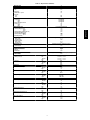
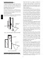
Step 6 —Install External Trap for Condensate
Drain
The unit’s 3/4-in. condensate drain connections are located on the
bottom and side of the unit. If the down drain is used, drill a
minimum of a 5/8-in. diameter hole but not larger than a 3/4-in.
diameter hole through the drain pan. A dimple of 2 mm in
diameter and 1.5 mm deep will be provided in the drain pan to
help locate the drill bit and to start the hole. Do not cut through
the PVC pipe threads. Unit discharge connections do not
determine the use of drain connections; either drain connection
can be used with vertical or horizontal applications. See Fig. 3
and 4 for locations.
When using the standard side drain connection, make sure the
plug (red) in the alternate bottom connection is tight before
installing the unit. (See Fig. 8.)
To use the bottom drain connection for a roof curb installation,
relocate the factory-installed plug (red) from the bottom
connection to the side connection. A 1/2-in. socket extension can
be used to remove the plug. (See Fig. 8.) The piping for the
condensate drain and external trap can be completed after the unit
is in place.
All units must have an external trap for condensate drainage.
Install a trap at least 4-in. deep and protect against freeze-up. If
drain line is installed downstream from the external trap, pitch the
line away from the unit at 1-in. per 10 ft of run. Do not use a pipe
size smaller than the unit connection (3/4-in.). (See Fig. 9 and 10.)
The 50PG units are provided with a removable condensate pan
for ease of cleaning. It is recommended that a union be placed
between the unit and condensate drainage to ease the removal of
the pan during servicing. Adequate clearance should be allowed if
removal of condensate pan is required. Allow 64 in. (08-14) or
93-in. (16) between condensate pan access panel and any
obstruction for complete removal.
ELECTRICAL OPERATION HAZARD
Failure to follow this warning could result in personal
injury or death.
For vertical supply and return units, tools or parts could
drop into ductwork and cause an injury. Install a
90--degree turn in the return ductwork between the unit
and the conditioned space. If a 90--degree elbow cannot
be installed, then a grille of sufficient strength and
density should be installed to prevent objects from
falling into the conditioned space.
11
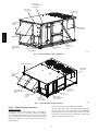
50PG08---16
Installation Onto Curb
The 50PG units are designed to fit on the accessory full perimeter
curb. In either case, correct placement of the unit onto the curb is
critical to operating performance. To aid in correct positioning,
place unit on roof curb to maintain 1/4-in. gap between the inside
of rail and roof curb on long sides and a 1/2-in. gap between the
inside of rail and roof curb on both duct and condenser ends.
Refer to Fig. 1--4, to assure proper duct opening alignment.
NOTE: Make sure the bottom drain condensate connection plug
is tight before installing unit on curb. See Step 6 — Install
External Trap for Condensate Drain.
CONTROL BOX
AND COMPRESSOR
ACCESS DOOR
ELECTRICAL
OPTIONS PANEL
INDOOR MOTOR
ACCESS DOOR
OUTDOOR AIR
SCREEN
(HIDDEN)
50PG08---16
CONDENSER COIL
ACCESS PANEL
ECONOMIZER
HOOD
BAROMETRIC
RELIEF DAMPER
HOOD
FILTER ACCESS
DOOR
BASEPAN CONNECTIONS
ACCESS PANEL
ELECTRIC
HEAT ACCESS
PANEL
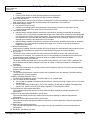
C06315
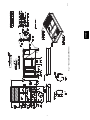
Fig. 6 --- Panel and Filter Locations (50PG08--14)
ECONOMIZER HOODS
CONDENSER
COIL ACCESS
PANEL
OUTDOOR AIR
SCREENS
(HIDDEN)
ELECTRIC
HEAT ACCESS
PANEL
BAROMETRIC
RELIEF DAMPER
HOODS
FILTER
ACCESS DOOR
ELECTRICAL
OPTIONS
PANEL
CONTROL BOX
AND COMPRESSOR
ACCESS DOOR
BASEPAN
CONNECTIONS
ACCESS PANEL
Fig. 7 --- Panel and Filter Locations (50PG16)
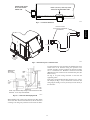
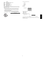
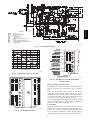
Step 7 —Make Electrical Connections
Field Power Supply
All 208/230-v units are factory wired for 230-v power supply. If
the 208/230-v unit is to be connected to a 208-v power supply,
the transformer must be rewired by moving the black wire with
the 1/4-in. female quick connect from the 230-volt connection and
moving to the 200-volt 1/4-in. male terminal on the primary side
of the transformer.
C06309
Refer to unit label diagram for additional information.
All field wiring must comply with NEC (National Electrical
Code) and local codes. Size wire based on MCA (Minimum
Circuit Amps) on the unit informative plate. Leads are provided
for field wire connections. Use UL (Underwriters’ Laboratories)
approved copper/aluminum connector.
12
INSERT SIDE DRAIN
PLUG FOR DOWN
DRAIN USE.
DRILL 5/8” DIA. (0.625 mm) HOLE
THRU FOR DOWN DRAIN USE.
Fig. 8 --- Condensate Drain Pan
C10321
50PG08---16
OPTIONAL UNIONS
TO ALLOW FOR CONDENSATE
PAN REMOVAL
4" (102mm)
CONDENSATE
PAN ACCESS
PANEL
Fig. 9 --- External Trap for Condensate Drain
C06234
If a fused disconnect is used, determine the minimum size for the
switch based on the disconnect sizing data provided in the
electrical data tables and then coordinate the disconnect housing
size to accommodate the Maximum Overcurrent Protection
(MOCP) device size as marked on the unit informative plate. (See
Tables 3 and 4.)
See Fig. 11 for power wiring connection to unit leads and
equipment ground.
Route power and ground lines through control box end panel or
unit basepan (see Fig. 3 and 4) to connections as shown on unit
wiring diagram and Fig. 8. Factory leads may be wired directly to
the disconnect.
NOTE: Trap should be deep enough to offset maximum unit static
difference. A 4-in. trap is recommended.
Fig. 10 --- Condensate Drain Piping Details
C06235
When installing units, provide safety disconnect per NEC Article
440 or local codes. For non-fused disconnects, size the disconnect
according to the sizing data provided in the electrical data tables.
13
!
CAUTION
C.A1
DISCONNECT
PER NEC
UNIT DAMAGE HAZARD
Failure to follow this caution may result in damage to the
unit.
The correct power phasing is critical to the operation of the
scroll compressors. An incorrect phasing will result in an
alarm and compressor operation lockout. Should this occur,
power phase correction must be made to the incoming
power. Damage to compressor could result.
!
FIELD
FACTOR
POWER
POWER
WIRING
WIRING
11
21
12
22
13
23
EQUIP GND
WARNING
C06237
Fig. 11 --- Field Power Wiring Connections
50PG08---16
ELECTRICAL SHOCK HAZARD
Failure to follow this warning could result in personal
injury or death.
THERMOSTAT ASSEMBLY
REMOVABLE JUMPER
Unit cabinet must have an uninterrupted, unbroken
electrical ground to minimize the possibility of personal
injury if an electrical fault should occur. This ground
may consist of electrical wire connected to unit ground
lug in control compartment, or conduit approved for
electrical ground when installed in accordance with
NEC; ANSI/NFPA (National Fire Protection
Association), latest edition, and local electrical codes.
Field wiring must conform to temperature limitations for type “T”
wire. All field wiring must comply with NEC and local
requirements.
Operating voltage to compressor must be within voltage range
indicated on unit nameplate. Voltages between phases must be
balanced within 2%.
Unit failure as a result of operation on improper line voltage or
excessive phase imbalance constitutes abuse and may cause
damage to electrical components.
Field Control Wiring
Unit can be controlled with a Carrier-approved accessory
thermostat. Install thermostat according to the installation
instructions included with accessory. Locate thermostat assembly
on a solid interior wall in the conditioned space to sense average
temperature.
Route thermostat cable or equivalent single leads of colored wire
from subbase terminals through conduit into unit to low-voltage
connections as shown on unit label wiring diagram and in Fig.
12.
RH
TB1
R
RC
Y1
Y2
W1
W2
G
C
Y1
Y2
W1
W2
G
C
Fig. 12 --- Field Control Thermostat Wiring
L
X
X
C06238
NOTE: For wire runs up to 50 ft, use no. 18 AWG (American
Wire Gauge) insulated wire (35_C minimum). For 50 to 75 ft, use
no. 16 AWG insulated wire (35_C minimum). For over 75 ft, use
no. 14 AWG insulated wire (35_C Minimum). All wire larger
than no. 18 AWG cannot be directly connected at the thermostat
and will require a junction box and splice at the thermostat.
Set heat anticipator settings as follows:
VOLTAGE
All
STAGE 1
(W1) ON
0.2
STAGE 1 AND 2
(W1 AND W2) ON
0.4
Settings may be changed slightly to provide a greater degree of
comfort for a particular installation.
14
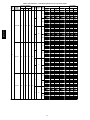
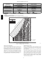
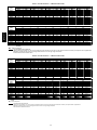
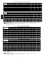
Table 3—Electrical Data — Units Without Optional Powered Convenience Outlet
OFM
FLA
IFM
FLA
POWER
IFM
EXHAUST TYPE
FLA
5.2
Low
—
208/230-3-60
187
253
13.5
88
7.5
High
5.2
Low
1.5
3.0
7.5
High
2.6
Low
—
3.4
High
2.6
Low
08
460-3-60
414
506
6.4
39
0.8
1.2
3.4
High
Low
2.0
—
High
575-3-60
518
632
6.4
30.0
0.8
Low
2.8
3.0
High
ELECTRIC HEAT
POWER SUPPLY
DISCONNECT
SIZE
CRHEATER
PART NO.
FLA
NOMINAL
KW*
MCA
MOCP†
FLA
LRA
—
225A00
226A00
227A00
228A00
229A00
—
225A00
226A00
227A00
228A00
229A00
—
225A00
226A00
227A00
228A00
229A00
—
225A00
226A00
227A00
228A00
229A00
—
232A00
233A00
234A00
235A00
236A00
—
232A00
233A00
234A00
235A00
236A00
—
232A00
233A00
234A00
235A00
236A00
—
232A00
233A00
234A00
235A00
236A00
—
239A00
240A00
241A00
242A00
—
239A00
240A00
241A00
242A00
—
239A00
240A00
241A00
242A00
—
239A00
240A00
241A00
242A00
—
20.0/23.1
30.0/34.6
50.0/57.7
70.0/80.8
80.0/92.4
—
20.0/23.1
30.0/34.6
50.0/57.7
70.0/80.8
80.0/92.4
—
20.0/23.1
30.0/34.6
50.0/57.7
70.0/80.8
80.0/92.4
—
20.0/23.1
30.0/34.6
50.0/57.7
70.0/80.8
80.0/92.4
—
11.5
17.3
28.9
40.4
46.2
—
11.5
17.3
28.9
40.4
46.2
—
11.5
17.3
28.9
40.4
46.2
—
11.5
17.3
28.9
40.4
46.2
—
13.9
23.1
32.3
37.0
—
13.9
23.1
32.3
37.0
—
13.9
23.1
32.3
37.0
—
13.9
23.1
32.3
37.0
—/—
7.5/10.0
11.3/15.0
18.8/25.0
26.3/35.0
30.0/40.0
—/—
7.5/10.0
11.3/15.0
18.8/25.0
26.3/35.0
30.0/40.0
—/—
7.5/10.0
11.3/15.0
18.8/25.0
26.3/35.0
30.0/40.0
—/—
7.5/10.0
11.3/15.0
18.8/25.0
26.3/35.0
30.0/40.0
—
10.0
15.0
25.0
35.0
40.0
—
10.0
15.0
25.0
35.0
40.0
—
10.0
15.0
25.0
35.0
40.0
—
10.0
15.0
25.0
35.0
40.0
—
15.0
25.0
35.0
40.0
—
15.0
25.0
35.0
40.0
—
15.0
25.0
35.0
40.0
—
15.0
25.0
35.0
40.0
38.5/ 38.5
38.5/ 38.5
44.0/ 49.8
69.0/ 78.7
94.1/107.5
106.6/122.0
40.8/ 40.8
40.8/ 40.8
46.9/ 52.7
71.9/ 81.5
96.9/110.4
109.4/124.8
41.5/ 41.5
41.5/ 41.5
47.8/ 53.6
72.8/ 82.4
97.8/111.3
110.3/125.7
43.8/ 43.8
43.8/ 43.8
50.6/ 56.4
75.7/ 85.3
100.7/114.2
113.2/128.6
18.6
18.6
24.9
39.3
53.8
61.0
19.4
19.4
25.9
40.3
54.8
62.0
19.8
19.8
26.4
40.8
55.3
62.5
20.6
20.6
27.4
41.8
56.3
63.5
18.0
20.1
31.4
42.9
48.7
18.8
20.8
32.4
43.9
49.7
18.1
23.6
35.1
46.7
52.4
18.9
24.6
36.1
47.7
53.4
50/ 50
50/ 50
50/ 50
70/ 80
100/110
110/125
50/ 50
50/ 50
50/ 60
80/ 90
100/125
110/125
50/ 50
50/ 50
50/ 60
80/ 90
100/125
125/150
50/ 50
50/ 50
60/ 60
80/ 90
110/125
125/150
25
25
25
40
60
70
25
25
30
45
60
70
25
25
30
45
60
70
25
25
30
45
60
70
20
20
35
45
50
20
25
35
45
50
20
25
40
50
60
25
25
40
50
60
40/ 40
40/ 40
41/ 46
64/ 72
87/ 99
98/112
43/ 43
43/ 43
43/ 48
66/ 75
89/102
101/115
44/ 44
44/ 44
44/ 49
67/ 76
90/102
101/116
46/ 46
46/ 46
47/ 52
70/ 78
93/105
104/118
20
20
23
36
49
56
20
20
24
37
50
57
21
21
24
38
51
57
22
22
25
38
52
58
19
19
29
39
45
20
20
30
40
46
19
22
32
43
48
20
23
33
44
49
212/212
212/212
212/212
212/212
212/212
212/212
238/238
238/238
238/238
238/238
238/238
238/238
216/216
216/216
216/216
216/216
216/216
216/216
242/242
242/242
242/242
242/242
242/242
242/242
96
96
96
96
96
96
109
109
109
109
109
109
99
99
99
99
99
99
112
112
112
112
112
112
84
84
84
84
84
102
102
102
102
102
86
86
86
86
86
98
98
98
98
98
15
50PG08---16
VOLTAGE COMPRESSOR
NOMINAL
RANGE
(EA.)
UNIT
POWER
50PG
SUPPLY
MIN MAX
RLA
LRA
VOLTS-PH-HZ
Table 3 — Electrical Data — Units Without Optional Powered Convenience Outlet (cont)
UNIT
50PG
VOLTAGE COMPRESSOR
NOMINAL
RANGE
(EA.)
POWER
OFM
SUPPLY
FLA
MIN
MAX
RLA
LRA
VOLTS-PH-HZ
IFM
FLA
ELECTRIC HEAT
POWER
EXHAUST IFM
TYPE CRHEATER
NOMINAL
FLA
FLA
PART NO.
KW*
Low
—
High
208/230-3-60
187
253
16.0
91
1.5
5.2
50PG08---16
Low
3.0
High
2.6
Low
—
4.8
High
2.6
Low
09
460-3-60
414
506
7.1
46
0.8
1.2
4.8
High
2.0
Low
—
575-3-60
518
632
5.6
37.0
3.3
High
2.0
Low
0.8
3.0
3.3
High
—
225A00
226A00
227A00
228A00
229A00
—
225A00
226A00
227A00
228A00
229A00
—
225A00
226A00
227A00
228A00
229A00
—
225A00
226A00
227A00
228A00
229A00
—
232A00
233A00
234A00
235A00
236A00
—
232A00
233A00
234A00
235A00
236A00
—
232A00
233A00
234A00
235A00
236A00
—
232A00
233A00
234A00
235A00
236A00
—
239A00
240A00
241A00
242A00
—
239A00
240A00
241A00
242A00
—
239A00
240A00
241A00
242A00
—
239A00
240A00
241A00
242A00
16
—
20.0/23.1
30.0/34.6
50.0/57.7
70.0/80.8
80.0/92.4
—
20.0/23.1
30.0/34.6
50.0/57.7
70.0/80.8
80.0/92.4
—
20.0/23.1
30.0/34.6
50.0/57.7
70.0/80.8
80.0/92.4
—
20.0/23.1
30.0/34.6
50.0/57.7
70.0/80.8
80.0/92.4
—
11.5
17.3
28.9
40.4
46.2
—
11.5
17.3
28.9
40.4
46.2
—
11.5
17.3
28.9
40.4
46.2
—
11.5
17.3
28.9
40.4
46.2
—
13.9
23.1
32.3
37.0
—
13.9
23.1
32.3
37.0
—
13.9
23.1
32.3
37.0
—
13.9
23.1
32.3
37.0
—/—
7.5/10.0
11.3/15.0
18.8/25.0
26.3/35.0
30.0/40.0
—/—
7.5/10.0
11.3/15.0
18.8/25.0
26.3/35.0
30.0/40.0
—/—
7.5/10.0
11.3/15.0
18.8/25.0
26.3/35.0
30.0/40.0
—/—
7.5/10.0
11.3/15.0
18.8/25.0
26.3/35.0
30.0/40.0
—
10.0
15.0
25.0
35.0
40.0
—
10.0
15.0
25.0
35.0
40.0
—
10.0
15.0
25.0
35.0
40.0
—
10.0
15.0
25.0
35.0
40.0
—
15.0
25.0
35.0
40.0
—
15.0
25.0
35.0
40.0
—
15.0
25.0
35.0
40.0
—
15.0
25.0
35.0
40.0
POWER SUPPLY
DISCONNECT
SIZE
MCA
MOCP†
FLA
LRA
44.3/ 44.3
44.3/ 44.3
44.3/ 49.8
69.0/ 78.7
94.1/107.5
106.6/122.0
49.3/ 49.3
49.3/ 49.3
50.3/ 56.1
75.3/ 84.9
100.3/113.8
112.8/128.2
47.3/ 47.3
47.3/ 47.3
47.8/ 53.6
72.8/ 82.4
97.8/111.3
110.3/125.7
52.3/ 52.3
52.3/ 52.3
54.0/ 59.8
79.0/ 88.7
104.1/117.5
116.6/132.0
20.1
20.1
24.9
39.3
53.8
61.0
22.3
22.3
27.7
42.1
56.5
63.7
21.3
21.3
26.4
40.8
55.3
62.5
23.5
23.5
29.2
43.6
58.0
65.2
16.2
20.1
31.4
42.9
48.7
17.5
21.4
33.0
45.1
50.3
19.1
23.6
35.1
46.7
52.4
19.9
24.6
36.1
47.7
53.4
60/ 60
60/ 60
60/ 60
70/ 80
100/110
110/125
60/ 60
60/ 60
60/ 60
80/ 90
110/125
125/150
60/ 60
60/ 60
60/ 60
80/ 90
100/125
125/150
60/ 60
60/ 60
60/ 60
80/ 90
110/125
125/150
25
25
25
40
60
70
25
25
30
45
60
70
25
25
30
45
60
70
30
30
30
45
60
70
20
20
35
45
50
20
25
35
45
50
25
25
40
50
60
25
25
40
50
60
46/ 46
46/ 46
46/ 46
64/ 72
87/ 99
98/112
52/ 52
52/ 52
52/ 52
69/ 78
92/105
104/118
50/ 50
50/ 50
50/ 50
67/ 76
90/102
101/116
55/ 55
55/ 55
55/ 55
73/ 82
96/108
107/121
21
21
23
36
49
56
24
24
25
39
52
59
22
22
24
38
51
57
25
25
27
40
53
60
17
18
29
39
45
19
20
30
41
46
20
22
32
43
48
21
23
33
44
49
218/218
218/218
218/218
218/218
218/218
218/218
261/261
261/261
261/261
261/261
261/261
261/261
222/222
222/222
222/222
222/222
222/222
222/222
265/265
265/265
265/265
265/265
265/265
265/265
110
110
110
110
110
110
132
132
132
132
132
132
113
113
113
113
113
113
134
134
134
134
134
134
98
98
98
98
98
136
136
136
136
136
92
92
92
92
92
104
104
104
104
104
% Voltage Imbalance
= 100 x
max voltage deviation from average voltage
average voltage
Example: Supply voltage is 460-3-60
AB = 224 v
BC = 231 v
AC = 226 v
Average Voltage =
=
=
224 + 231 + 226
3
681
3
227
Determine maximum deviation from average voltage.
(AB) 227 – 224 = 3 v
(BC) 231 – 227 = 4 v
(AC) 227 – 226 = 1 v
Maximum deviation is 4 v.
Determine percent of voltage imbalance.
% Voltage Imbalance
= 100 x
4
227
= 1.76%
This amount of phase imbalance is satisfactory as it is below the maximum allowable 2%.
IMPORTANT: If the supply voltage phase imbalance is more than 2%, contact your local electric
utility company immediately.
17
50PG08---16
LEGEND
FLA
--- Full Load Amps
HACR --- Heating, Air Conditioning and Refrigeration
IFM
--- Indoor (Evaporator) Fan Motor
LRA
--- Locked Rotor Amps
MCA --- Minimum Circuit Amps
MOCP --- Maximum Overcurrent Protection
NEC
--- National Electrical Code
OFM
--- Outdoor (Condenser) Fan Motor
RLA
--- Rated Load Amps
* Heater capacity (kW) is based on heater voltage of 208 v, 230 v, 480 v, or 600 v. If power
distribution voltage to unit varies from rated heater voltage, heater kW will vary accordingly.
{ Fuse or HACR circuit breaker.
NOTES:
1. In compliance with NEC requirements for multimotor and combination load equipment (refer to NEC Articles 430 and 440), the overcurrent protective device for the
unit shall be fuse or HACR breaker. Canadian units may be fuse or circuit breaker.
2. Unbalanced 3-Phase Supply Voltage
Never operate a motor where a phase imbalance in supply voltage is greater than
2%. Use the following formula to determine the percentage of voltage imbalance.
Table 3 — Electrical Data — Units Without Optional Powered Convenience Outlet (cont)
VOLTAGE COMPRESSOR
NOMINAL
RANGE
(EA.)
UNIT
OFM
POWER
50PG
FLA
SUPPLY
MIN MAX
RLA
LRA
VOLTS-PH-HZ
ELECTRIC HEAT
POWER
IFM
IFM
FLA EXHAUST TYPE CRHEATER
NOMINAL
FLA
FLA
PART NO.
KW*
7.5
Low
—
187
253
17.6
123
High
7.5
Low
1.9
50PG08---16
208/230-3-60
10.2
3.0
10.2
High
3.4
Low
—
4.8
High
3.4
Low
12
460-3-60
414
506
7.7
50
1.0
1.2
4.8
High
2.8
Low
—
575-3-60
518
632
6.1
40.0
3.3
High
2.8
Low
0.8
3.0
3.3
High
—
225A00
226A00
227A00
228A00
229A00
230A00
—
225A00
226A00
227A00
228A00
229A00
230A00
—
225A00
226A00
227A00
228A00
229A00
230A00
—
225A00
226A00
227A00
228A00
229A00
230A00
—
232A00
233A00
234A00
235A00
236A00
237A00
—
232A00
233A00
234A00
235A00
236A00
237A00
—
232A00
233A00
234A00
235A00
236A00
237A00
—
232A00
233A00
234A00
235A00
236A00
237A00
—
239A00
240A00
241A00
242A00
243A00
—
239A00
240A00
241A00
242A00
243A00
—
239A00
240A00
241A00
242A00
243A00
—
239A00
240A00
241A00
242A00
243A00
18
—
20.0/ 23.1
30.0/ 34.6
50.0/ 57.7
70.0/ 80.8
80.0/ 92.4
100.1/115.5
—
20.0/ 23.1
30.0/ 34.6
50.0/ 57.7
70.0/ 80.8
80.0/ 92.4
100.1/115.5
—
20.0/ 23.1
30.0/ 34.6
50.0/ 57.7
70.0/ 80.8
80.0/ 92.4
100.1/115.5
—
20.0/ 23.1
30.0/ 34.6
50.0/ 57.7
70.0/ 80.8
80.0/ 92.4
100.1/115.5
—
11.5
17.3
28.9
40.4
46.2
57.7
—
11.5
17.3
28.9
40.4
46.2
57.7
—
11.5
17.3
28.9
40.4
46.2
57.7
—
11.5
17.3
28.9
40.4
46.2
57.7
—
13.9
23.1
32.3
37.0
46.2
—
13.9
23.1
32.3
37.0
46.2
—
13.9
23.1
32.3
37.0
46.2
—
13.9
23.1
32.3
37.0
46.2
—/—
7.5/10.0
11.3/15.0
18.8/25.0
26.3/35.0
30.0/40.0
37.6/50.0
—/—
7.5/10.0
11.3/15.0
18.8/25.0
26.3/35.0
30.0/40.0
37.6/50.0
—/—
7.5/10.0
11.3/15.0
18.8/25.0
26.3/35.0
30.0/40.0
37.6/50.0
—/—
7.5/10.0
11.3/15.0
18.8/25.0
26.3/35.0
30.0/40.0
37.6/50.0
—
10.0
15.0
25.0
35.0
40.0
50.0
—
10.0
15.0
25.0
35.0
40.0
50.0
—
10.0
15.0
25.0
35.0
40.0
50.0
—
10.0
15.0
25.0
35.0
40.0
50.0
—
15.0
25.0
35.0
40.0
50.0
—
15.0
25.0
35.0
40.0
50.0
—
15.0
25.0
35.0
40.0
50.0
—
15.0
25.0
35.0
40.0
50.0
POWER SUPPLY
DISCONNECT
SIZE
MCA
MOCP†
FLA
LRA
51.0/ 51.0
51.0/ 51.0
51.0/ 52.7
71.9/ 81.5
96.9/110.4
109.4/124.8
134.5/124.8
53.7/ 53.7
53.7/ 53.7
53.7/ 56.1
75.3/ 84.9
100.3/113.8
112.8/128.2
137.8/128.2
54.0/ 54.0
54.0/ 54.0
54.0/ 56.4
75.7/ 85.3
100.7/114.2
113.2/128.6
138.2/128.6
56.7/ 56.7
56.7/ 56.7
56.7/ 59.8
79.0/ 88.7
104.1/117.5
116.6/132.0
141.6/132.0
22.7
22.7
25.9
40.3
54.8
62.0
62.0
24.1
24.1
27.7
42.1
56.5
63.7
63.7
23.9
23.9
27.4
41.8
56.3
63.5
63.5
25.3
25.3
29.2
43.6
58.0
65.2
65.2
20.1
20.8
32.4
43.9
49.7
49.7
18.6
21.4
33.0
45.1
50.3
50.3
21.1
24.6
36.1
47.7
53.4
53.4
21.1
24.6
36.1
47.7
53.4
53.4
60/ 60
60/ 60
60/ 60
80/ 90
100/125
110/125
150/150
60/ 60
60/ 60
60/ 60
80/ 90
110/125
125/150
150/150
60/ 60
60/ 60
60/ 60
80/ 90
110/125
125/150
150/150
70/ 70
70/ 70
70/ 70
80/ 90
110/125
125/150
150/150
30
30
30
45
60
70
70
30
30
30
45
60
70
70
30
30
30
45
60
70
70
30
30
30
45
60
70
70
20
25
35
45
50
60
20
25
35
45
50
60
25
25
40
50
60
60
25
25
40
50
60
60
54/ 54
54/ 54
54/ 54
66/ 75
89/102
101/115
124/141
57/ 57
57/ 57
57/ 57
69/ 78
92/105
104/118
127/145
57/ 57
57/ 57
57/ 57
70/ 78
93/105
104/118
127/145
60/ 60
60/ 60
60/ 60
73/ 82
96/108
107/121
130/148
24
24
24
37
50
57
70
26
26
26
39
52
59
72
25
25
25
38
52
58
72
27
27
27
40
53
60
73
21
21
32
42
48
58
20
20
30
41
46
57
23
23
33
44
49
60
23
23
33
44
49
60
314/314
314/314
314/314
314/314
314/314
314/314
314/314
331/331
331/331
331/331
331/331
331/331
331/331
331/331
318/318
318/318
318/318
318/318
318/318
318/318
318/318
335/335
335/335
335/335
335/335
335/335
335/335
335/335
130
130
130
130
130
130
130
139
139
139
139
139
139
139
133
133
133
133
133
133
133
141
141
141
141
141
141
141
124
124
124
124
124
124
142
142
142
142
142
142
110
110
110
110
110
110
110
110
110
110
110
110
Table 3 — Electrical Data — Units Without Optional Powered Convenience Outlet (cont)
VOLTAGE
NOMINAL
RANGE
POWER
SUPPLY
VOLTS-PH-HZ MIN MAX
COMPRESS
OR
OFM
(EA.)
FLA
RLA LRA
IFM
FLA
ELECTRIC HEAT
POWER
IFM
EXHAUST TYPE
FLA
CRHEATER
NOMINAL
FLA
PART NO.
KW*
10.2
Low
—
208/230-3-60
187
253
22.4
149
15.0
High
10.2
Low
1.9
3.0
15.0
High
4.8
Low
—
14
460-3-60
414
506
10.6
75
7.4
High
4.8
Low
1.0
1.2
7.4
High
3.3
Low
—
575-3-60
518
632
10.6
59.0
5.6
High
3.3
Low
0.8
3.0
5.6
High
—
225A00
226A00
227A00
228A00
230A00
231A00
—
225A00
226A00
227A00
228A00
230A00
231A00
—
225A00
226A00
227A00
228A00
230A00
231A00
—
225A00
226A00
227A00
228A00
230A00
231A00
—
232A00
233A00
234A00
235A00
237A00
238A00
—
232A00
233A00
234A00
235A00
237A00
238A00
—
232A00
233A00
234A00
235A00
237A00
238A00
—
232A00
233A00
234A00
235A00
237A00
238A00
—
239A00
240A00
241A00
242A00
243A00
244A00
—
239A00
240A00
241A00
242A00
243A00
244A00
—
239A00
240A00
241A00
242A00
243A00
244A00
—
239A00
240A00
241A00
242A00
243A00
244A00
19
—
20.0/ 23.1
30.0/ 34.6
50.0/ 57.7
70.0/ 80.8
100.1/115.5
120.1/138.6
—
20.0/ 23.1
30.0/ 34.6
50.0/ 57.7
70.0/ 80.8
100.1/115.5
120.1/138.6
—
20.0/ 23.1
30.0/ 34.6
50.0/ 57.7
70.0/ 80.8
100.1/115.5
120.1/138.6
—
20.0/ 23.1
30.0/ 34.6
50.0/ 57.7
70.0/ 80.8
100.1/115.5
120.1/138.6
—
11.5
17.3
28.9
40.4
57.7
69.3
—
11.5
17.3
28.9
40.4
57.7
69.3
—
11.5
17.3
28.9
40.4
57.7
69.3
—
11.5
17.3
28.9
40.4
57.7
69.3
—
13.9
23.1
32.3
37.0
46.2
55.4
—
13.9
23.1
32.3
37.0
46.2
55.4
—
13.9
23.1
32.3
37.0
46.2
55.4
—
13.9
23.1
32.3
37.0
46.2
55.4
—/—
7.5/10.0
11.3/15.0
18.8/25.0
26.3/35.0
37.6/50.0
45.1/60.0
—/—
7.5/10.0
11.3/15.0
18.8/25.0
26.3/35.0
37.6/50.0
45.1/60.0
—/—
7.5/10.0
11.3/15.0
18.8/25.0
26.3/35.0
37.6/50.0
45.1/60.0
—/—
7.5/10.0
11.3/15.0
18.8/25.0
26.3/35.0
37.6/50.0
45.1/60.0
—
10.0
15.0
25.0
35.0
50.0
60.0
—
10.0
15.0
25.0
35.0
50.0
60.0
—
10.0
15.0
25.0
35.0
50.0
60.0
—
10.0
15.0
25.0
35.0
50.0
60.0
—
15.0
25.0
35.0
40.0
50.0
60.0
—
15.0
25.0
35.0
40.0
50.0
60.0
—
15.0
25.0
35.0
40.0
50.0
60.0
—
13.9
23.1
32.3
37.0
46.2
55.4
POWER SUPPLY
DISCONNECT
SIZE
MCA
MOCP†
FLA
LRA
64.5/ 64.5
64.5/ 64.5
64.5/ 64.5
75.3/ 84.9
100.3/113.8
137.8/128.2
162.8/151.3
69.3/ 69.3
69.3/ 69.3
69.3/ 69.3
81.3/ 90.9
106.3/119.8
143.8/134.2
168.8/157.3
67.5/ 67.5
67.5/ 67.5
67.5/ 67.5
79.0/ 88.7
104.1/117.5
141.6/132.0
166.6/155.1
72.3/ 72.3
72.3/ 72.3
72.3/ 72.3
85.0/ 94.7
110.1/123.5
147.6/138.0
172.6/161.1
30.6
30.6
30.6
42.1
56.5
63.7
75.3
33.2
33.2
33.2
45.3
59.8
67.0
78.5
31.8
31.8
31.8
43.6
58.0
65.2
76.8
34.4
34.4
34.4
46.8
61.3
68.5
80.0
28.7
28.7
33.0
45.1
50.3
50.3
59.6
31.0
31.0
35.9
47.4
53.2
53.2
62.4
24.7
24.7
36.1
47.7
53.4
53.4
62.7
27.5
28.1
39.6
51.2
56.9
56.9
66.2
80/ 80
80/ 80
80/ 80
80/ 90
110/125
150/150
175/175
90/ 90
90/ 90
90/ 90
90/100
110/125
150/150
175/175
80/ 80
80/ 80
80/ 80
80/ 90
110/125
150/150
175/175
90/ 90
90/ 90
90/ 90
90/100
125/125
150/150
175/175
40
40
40
45
60
70
90
40
40
40
50
60
80
90
40
40
40
45
60
70
90
45
45
45
50
70
80
90
25
25
35
45
50
60
60
30
30
40
50
60
60
70
30
30
40
50
60
60
70
30
30
40
60
60
60
70
68/ 68
68/ 68
68/ 68
69/ 78
92/105
127/145
150/171
73/ 73
73/ 73
73/ 73
75/ 84
98/110
132/150
155/177
71/ 71
71/ 71
71/ 71
73/ 82
96/108
130/148
153/175
77/ 77
77/ 77
77/ 77
78/ 87
101/114
136/153
159/180
32
32
32
39
52
72
85
35
35
35
42
55
75
88
34
34
34
40
53
73
87
37
37
37
43
56
76
90
30
30
30
41
46
57
68
33
33
33
44
49
60
70
26
26
33
44
49
60
70
29
29
36
47
52
63
74
383/383
383/383
383/383
383/383
383/383
383/383
383/383
391/391
391/391
391/391
391/391
391/391
391/391
391/391
387/387
387/387
387/387
387/387
387/387
387/387
387/387
395/395
395/395
395/395
395/395
395/395
395/395
395/395
190
190
190
190
190
190
190
194
194
194
194
194
194
194
192
192
192
192
192
192
192
197
197
197
197
197
197
197
180
180
180
180
180
180
180
191
191
191
191
191
191
191
138
138
138
138
138
138
138
151
151
151
151
151
151
151
50PG08---16
UNIT
50PG
LEGEND
FLA
--- Full Load Amps
HACR --- Heating, Air Conditioning and Refrigeration
IFM
--- Indoor (Evaporator) Fan Motor
LRA
--- Locked Rotor Amps
MCA --- Minimum Circuit Amps
MOCP --- Maximum Overcurrent Protection
NEC
--- National Electrical Code
OFM
--- Outdoor (Condenser) Fan Motor
RLA
--- Rated Load Amps
* Heater capacity (kW) is based on heater voltage of 208 v, 230 v, 480 v, or 600 v. If power
distribution voltage to unit varies from rated heater voltage, heater kW will vary accordingly.
{ Fuse or HACR circuit breaker.
NOTES:
1. In compliance with NEC requirements for multimotor and combination load equipment (refer to NEC Articles 430 and 440), the overcurrent protective device for the
unit shall be fuse or HACR breaker. Canadian units may be fuse or circuit breaker.
2. Unbalanced 3-Phase Supply Voltage
Never operate a motor where a phase imbalance in supply voltage is greater than
2%. Use the following formula to determine the percentage of voltage imbalance.
50PG08---16
% Voltage Imbalance
= 100 x
max voltage deviation from average voltage
average voltage
Example: Supply voltage is 460-3-60
AB = 224 v
BC = 231 v
AC = 226 v
Average Voltage =
=
=
224 + 231 + 226
3
681
3
227
Determine maximum deviation from average voltage.
(AB) 227 – 224 = 3 v
(BC) 231 – 227 = 4 v
(AC) 227 – 226 = 1 v
Maximum deviation is 4 v.
Determine percent of voltage imbalance.
% Voltage Imbalance
= 100 x
4
227
= 1.76%
This amount of phase imbalance is satisfactory as it is below the maximum allowable 2%.
IMPORTANT: If the supply voltage phase imbalance is more than 2%, contact your local electric
utility company immediately.
20
Table 3 — Electrical Data — Units Without Optional Powered Convenience Outlet (cont)
VOLTAGE
RANGE
MIN
COMPR
NO. 1
MAX RLA LRA
COMPR
NO. 2
RLA LRA
COMPR
NO. 3
POWER
OF
EXHAUST
MFL
RLA LRA A QTY FLA
—
—
IFM
TYPE
IFM
FLA
Low
10.2
ELECTRIC HEAT
CRHEATER
PART NO.
—
255A00
256A00
257A00
—
255A00
256A00
257A00
—
255A00
256A00
257A00
—
255A00
256A00
257A00
—
255A00
256A00
257A00
—
255A00
256A00
257A00
—
258A00
259A00
260A00
—
258A00
259A00
260A00
—
258A00
259A00
260A00
—
258A00
259A00
260A00
—
258A00
259A00
260A00
—
258A00
259A00
260A00
—
261A00
262A00
263A00
—
261A00
262A00
263A00
—
261A00
262A00
263A00
—
261A00
262A00
263A00
—
261A00
262A00
263A00
—
261A00
262A00
263A00
Mid- 15.0
Low
High 19.4
208/230-3-60 187 253 18.1 137 18.1 137 17.6 123 1.9
Low
2
3.0
10.2
Mid- 15.0
Low
High 19.4
—
16
460-3-60
414 506
9.0 62
9.0 62
—
518 633
6.8 50
6.8 50
4.8
MidLow
7.4
High
9.7
Low
4.8
MidLow
7.4
High
9.7
Low
2.8
MidLow
5.6
High
7.8
Low
2.8
MidLow
5.6
High
7.8
7.7 50 1.0
2
575-3-60
—
Low
1.2
—
6.1 40 0.8
2
3.0
21
POWER SUPPLY
DISCONNECT SIZE
FLA
NOMINAL
KW*
MCA
MOCP
FLA
LRA
—
52.1/60.1
104.2/120.3
156.3/180.4
—
52.1/60.1
104.2/120.3
156.3/180.4
—
52.1/ 0.1
104.2/120.3
156.3/180.4
—
52.1/60.1
104.2/120.3
156.3/180.4
—
52.1/ 60.1
104.2/120.3
156.3/180.4
—
52.1/ 60.1
104.2/120.3
156.3/180.4
—
30.1
60.1
90.2
—
30.1
60.1
90.2
—
30.1
60.1
90.2
—
30.1
60.1
90.2
—
30.1
60.1
90.2
—
30.1
60.1
90.2
—
24.1
46.2
72.2
—
24.1
46.2
72.2
—
24.1
46.2
72.2
—
24.1
46.2
72.2
—
24.1
46.2
72.2
—
24.1
46.2
72.2
—/—
18.8/25.0
37.6/50.0
56.3/75.0
—/—
18.8/25.0
37.6/50.0
56.3/75.0
—/—
18.8/25.0
37.6/50.0
56.3/75.0
—/—
18.8/25.0
37.6/50.0
56.3/75.0
—/—
18.8/25.0
37.6/50.0
56.3/75.0
—/—
18.8/25.0
37.6/50.0
56.3/75.0
—/—
25.0
50.0
75.0
—/—
25.0
50.0
75.0
—/—
25.0
50.0
75.0
—/—
25.0
50.0
75.0
—/—
25.0
50.0
75.0
—/—
25.0
50.0
75.0
—/—
25.0
50.0
75.0
—/—
25.0
50.0
75.0
—/—
25.0
50.0
75.0
—/—
25.0
50.0
75.0
—/—
25.0
50.0
75.0
—/—
25.0
50.0
75.0
74.2/74.2
77.9/87.9
143.0/133.0
169.1/193.2
79.0/79.0
83.9/ 93.9
149.0/139.0
175.1/199.2
83.4/83.4
89.4/99.4
154.5/144.5
180.6/204.7
77.2/77.2
81.6/91.7
146.8/136.8
172.8/196.9
82.0/82.0
87.6/97.7
152.8/142.8
178.8/202.9
86.4/86.4
93.1/103.2
158.3/148.3
184.3/208.4
35.8
43.6
66.1
96.2
38.4
46.8
69.4
99.5
40.7
49.7
72.3
102.3
37.0
45.1
67.6
97.7
39.6
48.3
70.9
101.0
41.9
51.2
73.8
103.8
26.6
33.6
49.7
75.7
29.4
37.1
53.2
79.2
31.6
39.8
55.9
81.9
29.6
37.3
53.4
79.4
32.4
40.8
56.9
82.9
34.6
43.6
59.7
85.7
90/ 90
90/ 90
150/150
200/225
90/ 90
90/100
150/175
200/225
100/100
100/100
175/175
200/225
90/ 90
90/100
150/150
200/225
100/100
100/100
175/175
200/225
100/100
100/110
175/175
200/250
40
45
80
100
45
50
80
110
50
50
80
125
45
50
80
100
45
50
80
110
50
60
80
125
30
35
60
80
35
40
60
90
35
40
60
90
35
40
60
90
35
45
60
90
40
45
70
100
80/ 80
80/ 81
132/150
192/219
86/ 86
86/ 86
137/156
197/225
91/91
91/91
142/161
202/230
84/ 84
84/ 84
135/154
195/223
89/ 89
89/ 90
141/159
200/228
94/ 94
94/ 95
146/164
206/233
39
40
75
109
42
43
78
112
44
46
80
115
40
41
76
111
43
44
79
114
46
47
82
116
29
31
56
86
32
34
60
89
34
37
62
92
32
34
60
90
35
38
63
93
38
40
66
95
482/482
482/482
482/482
482/482
491/491
491/491
491/491
491/491
529/529
529/529
529/529
529/529
486/486
486/486
486/486
486/486
495/495
495/495
495/495
495/495
533/533
533/533
533/533
533/533
215
215
215
215
219
219
219
219
238
238
238
238
217
217
217
217
222
222
222
222
241
241
241
241
167
167
167
167
181
181
181
181
196
196
196
196
171
171
171
171
185
185
185
185
200
200
200
200
50PG08---16
UNIT
50PG
NOMINAL
POWER
SUPPLY
(V-PH-HZ)
Table 4—Electrical Data — Units With Optional Powered Convenience Outlet
UNIT
50PG
VOLTAGE COMPRESS
NOMINAL
ELECTRIC HEAT
POWER
RANGE
OR
POWER
OFM IFM EXHAUST IFM
SUPPLY
FLA FLA
TYPE CRHEATER
NOMINAL
FLA
MIN
MAX
RLA
LRA
FLA
VOLTS-PH-HZ
PART NO.
KW*
5.2
Low
—
187
253
13.5
88
High
5.2
Low
1.5
50PG08---16
208/230-3-60
7.5
3.0
7.5
High
2.6
Low
—
3.4
High
2.6
Low
08
460-3-60
414
506
6.4
39
0.8
1.2
3.4
High
Low
2.0
—
High
575-3-60
518
632
6.4
30.0
0.8
Low
2.8
3.0
High
—
225A00
226A00
227A00
228A00
229A00
—
225A00
226A00
227A00
228A00
229A00
—
225A00
226A00
227A00
228A00
229A00
—
225A00
226A00
227A00
228A00
229A00
—
232A00
233A00
234A00
235A00
236A00
—
232A00
233A00
234A00
235A00
236A00
—
232A00
233A00
234A00
235A00
236A00
—
232A00
233A00
234A00
235A00
236A00
—
239A00
240A00
241A00
242A00
—
239A00
240A00
241A00
242A00
—
239A00
240A00
241A00
242A00
—
239A00
240A00
241A00
242A00
22
—
20.0/23.1
30.0/34.6
50.0/57.7
70.0/80.8
80.0/92.4
—
20.0/23.1
30.0/34.6
50.0/57.7
70.0/80.8
80.0/92.4
—
20.0/23.1
30.0/34.6
50.0/57.7
70.0/80.8
80.0/92.4
—
20.0/23.1
30.0/34.6
50.0/57.7
70.0/80.8
80.0/92.4
—
11.5
17.3
28.9
40.4
46.2
—
11.5
17.3
28.9
40.4
46.2
—
11.5
17.3
28.9
40.4
46.2
—
11.5
17.3
28.9
40.4
46.2
—
13.9
23.1
32.3
37.0
—
13.9
23.1
32.3
37.0
—
13.9
23.1
32.3
37.0
—
13.9
23.1
32.3
37.0
—/—
7.5/10.0
11.3/15.0
18.8/25.0
26.3/35.0
30.0/40.0
—/—
7.5/10.0
11.3/15.0
18.8/25.0
26.3/35.0
30.0/40.0
—/—
7.5/10.0
11.3/15.0
18.8/25.0
26.3/35.0
30.0/40.0
—/—
7.5/10.0
11.3/15.0
18.8/25.0
26.3/35.0
30.0/40.0
—
10.0
15.0
25.0
35.0
40.0
—
10.0
15.0
25.0
35.0
40.0
—
10.0
15.0
25.0
35.0
40.0
—
10.0
15.0
25.0
35.0
40.0
—
15.0
25.0
35.0
40.0
—
15.0
25.0
35.0
40.0
—
15.0
25.0
35.0
40.0
—
15.0
25.0
35.0
40.0
POWER SUPPLY
DISCONNECT
SIZE
MCA
MOCP†
FLA
LRA
43.3/ 43.3
43.3/ 43.3
50.0/ 55.2
75.1/ 84.1
100.1/113.0
112.6/127.4
45.6/ 45.6
45.6/ 45.6
52.9/ 58.1
77.9/ 87.0
102.9/115.9
115.4/130.3
46.3/ 46.3
46.3/ 46.3
53.8/ 59.0
78.8/ 87.9
103.8/116.7
116.3/131.2
48.6/ 48.6
48.6/ 48.6
56.7/ 61.9
81.7/ 90.7
106.7/119.6
119.2/134.0
20.8
20.8
27.6
42.1
56.5
63.7
21.6
21.6
28.6
43.1
57.5
64.7
22.0
22.0
29.1
43.6
58.0
65.2
22.8
22.9
30.1
44.6
59.0
66.2
20.1
22.0
33.5
45.1
50.9
20.6
23.0
34.5
46.1
51.9
19.9
25.7
37.3
48.8
54.6
20.7
26.7
38.3
49.8
55.6
50/ 50
50/ 50
60/ 60
80/ 90
110/125
125/150
50/ 50
50/ 50
60/ 60
80/ 90
110/125
125/150
50/ 50
50/ 50
60/ 60
80/ 90
110/125
125/150
60/ 60
60/ 60
60/ 70
90/100
110/125
125/150
25
25
30
45
60
70
25
25
30
45
60
70
25
25
30
45
60
70
25
25
35
45
60
70
20
25
35
50
60
20
25
35
50
60
25
30
40
50
60
25
30
40
50
60
46/ 46
46/ 46
46/ 51
69/ 78
92/104
104/118
49/ 49
49 /49
49/ 54
72/ 81
95/107
106/120
49/ 49
49/ 49
49/ 55
72/ 81
96/108
107/121
52/ 52
52/ 52
52/ 57
75/ 84
98/111
110/124
22
22
25
39
52
59
23
23
26
40
53
60
23
23
27
40
53
60
24
24
28
41
54
61
21
21
31
41
47
22
22
32
42
48
21
24
34
45
50
22
25
35
46
51
217/217
217/217
217/217
217/217
217/217
217/217
243/243
243/243
243/243
243/243
243/243
243/243
221/221
221/221
221/221
221/221
221/221
221/221
247/247
247/247
247/247
247/247
247/247
247/247
98
98
98
98
98
98
111
111
111
111
111
111
101
101
101
101
101
101
114
114
114
114
114
114
86
86
86
86
86
104
104
104
104
104
88
88
88
88
88
100
100
100
100
100
Table 4 — Electrical Data — Units With Optional Powered Convenience Outlet (cont)
VOLTAGE
NOMINAL
COMPRESSOR
ELECTRIC HEAT
POWER
RANGE
POWER
OFM IFM EXHAUST IFM
SUPPLY
FLA FLA
TYPE CRHEATER
NOMINAL
FLA
MIN
MAX
RLA
LRA
FLA
VOLTS-PH-HZ
PART NO.
KW*
5.2
Low
—
208/230-3-60
187
253
16.0
91
10.2
High
5.2
Low
1.5
3.0
10.2
High
2.6
Low
—
4.8
High
2.6
Low
09
460-3-60
414
506
7.1
46
0.8
1.2
4.8
High
2.0
Low
—
575-3-60
518
632
5.6
37.0
3.3
High
2.0
Low
0.8
3.0
3.3
High
—
225A00
226A00
227A00
228A00
229A00
—
225A00
226A00
227A00
228A00
229A00
—
225A00
226A00
227A00
228A00
229A00
—
225A00
226A00
227A00
228A00
229A00
—
232A00
233A00
234A00
235A00
236A00
—
232A00
233A00
234A00
235A00
236A00
—
232A00
233A00
234A00
235A00
236A00
—
232A00
233A00
234A00
235A00
236A00
—
239A00
240A00
241A00
242A00
—
239A00
240A00
241A00
242A00
—
239A00
240A00
241A00
242A00
—
239A00
240A00
241A00
242A00
23
—
20.0/23.1
30.0/34.6
50.0/57.7
70.0/80.8
80.0/92.4
—
20.0/23.1
30.0/34.6
50.0/57.7
70.0/80.8
80.0/92.4
—
20.0/23.1
30.0/34.6
50.0/57.7
70.0/80.8
80.0/92.4
—
20.0/23.1
30.0/34.6
50.0/57.7
70.0/80.8
80.0/92.4
—
11.5
17.3
28.9
40.4
46.2
—
11.5
17.3
28.9
40.4
46.2
—
11.5
17.3
28.9
40.4
46.2
—
11.5
17.3
28.9
40.4
46.2
—
13.9
23.1
32.3
37.0
—
13.9
23.1
32.3
37.0
—
13.9
23.1
32.3
37.0
—
13.9
23.1
32.3
37.0
—/—
7.5/10.0
11.3/15.0
18.8/25.0
26.3/35.0
30.0/40.0
—/—
7.5/10.0
11.3/15.0
18.8/25.0
26.3/35.0
30.0/40.0
—/—
7.5/10.0
11.3/15.0
18.8/25.0
26.3/35.0
30.0/40.0
—/—
7.5/10.0
11.3/15.0
18.8/25.0
26.3/35.0
30.0/40.0
—
10.0
15.0
25.0
35.0
40.0
—
10.0
15.0
25.0
35.0
40.0
—
10.0
15.0
25.0
35.0
40.0
—
10.0
15.0
25.0
35.0
40.0
—
15.0
25.0
35.0
40.0
—
15.0
25.0
35.0
40.0
—
15.0
25.0
35.0
40.0
—
15.0
25.0
35.0
40.0
POWER SUPPLY
DISCONNECT
SIZE
MCA
MOCP†
FLA
LRA
49.1/ 49.1
49.1/ 49.1
50.0/ 55.2
75.1/ 84.1
100.1/113.0
112.6/127.4
54.1/ 54.1
54.1/ 54.1
56.3/ 61.5
81.3/ 90.4
106.3/119.2
118.8/133.7
52.1/ 52.1
52.1/ 52.1
53.8/ 59.0
78.8/ 87.9
103.8/116.7
116.3/131.2
57.1/ 57.1
57.1/ 57.1
60.0/ 65.2
85.1/ 94.1
110.1/123.0
122.6/137.4
22.2
22.2
27.6
42.1
56.5
63.7
24.4
24.4
30.4
44.8
59.2
66.5
23.4
23.4
29.1
43.6
58.0
65.2
25.6
25.6
31.9
46.3
60.7
68.0
17.9
22.0
33.5
45.1
50.9
19.2
23.6
35.2
46.7
52.5
20.9
25.7
37.3
48.8
54.6
21.7
26.7
38.3
49.8
55.6
60/ 60
60/ 60
60/ 60
80/ 90
110/125
125/150
60/ 60
60/ 60
60/ 70
90/100
110/125
125/150
60/ 60
60/ 60
60/ 60
80/ 90
110/125
125/150
70/ 70
70/ 70
70/ 70
90/100
125/125
125/150
25
25
30
45
60
70
30
30
35
45
60
70
30
30
30
45
60
70
30
30
35
50
70
70
20
25
35
50
60
25
25
35
50
60
25
30
40
50
60
25
30
40
50
60
52/ 52
52/ 52
52/ 52
69/ 78
92/104
104/118
58/ 58
58/ 58
58/ 58
75/ 84
98/110
109/123
55/ 55
55/ 55
55/ 55
72/ 81
96/108
107/121
61/ 61
61/ 61
61/ 61
78/ 87
101/114
113/127
24
24
25
39
52
59
26
26
28
41
54
61
25
25
27
40
53
60
27
27
29
43
56
63
19
20
31
41
47
21
22
32
43
48
22
24
34
45
50
23
25
35
46
51
223/223
223/223
223/223
223/223
223/223
223/223
266/266
266/266
266/266
266/266
266/266
266/266
227/227
227/227
227/227
227/227
227/227
227/227
270/270
270/270
270/270
270/270
270/270
270/270
112
112
112
112
112
112
134
134
134
134
134
134
115
115
115
115
115
115
136
136
136
136
136
136
100
100
100
100
100
138
138
138
138
138
94
94
94
94
94
105
105
105
105
105
50PG08---16
UNIT
50PG
LEGEND
FLA
--- Full Load Amps
HACR --- Heating, Air Conditioning and Refrigeration
IFM
--- Indoor (Evaporator) Fan Motor
LRA
--- Locked Rotor Amps
MCA --- Minimum Circuit Amps
MOCP --- Maximum Overcurrent Protection
NEC
--- National Electrical Code
OFM
--- Outdoor (Condenser) Fan Motor
RLA
--- Rated Load Amps
* Heater capacity (kW) is based on heater voltage of 208 v, 230 v, 480 v, or 600 v. If power
distribution voltage to unit varies from rated heater voltage, heater kW will vary accordingly.
{ Fuse or HACR circuit breaker.
NOTES:
1. In compliance with NEC requirements for multimotor and combination load equipment (refer to NEC Articles 430 and 440), the overcurrent protective device for the
unit shall be fuse or HACR breaker. Canadian units may be fuse or circuit breaker.
2. Unbalanced 3-Phase Supply Voltage
Never operate a motor where a phase imbalance in supply voltage is greater than
2%. Use the following formula to determine the percentage of voltage imbalance.
50PG08---16
% Voltage Imbalance
= 100 x
max voltage deviation from average voltage
average voltage
Example: Supply voltage is 460-3-60
AB = 224 v
BC = 231 v
AC = 226 v
Average Voltage =
=
=
224 + 231 + 226
3
681
3
227
Determine maximum deviation from average voltage.
(AB) 227 – 224 = 3 v
(BC) 231 – 227 = 4 v
(AC) 227 – 226 = 1 v
Maximum deviation is 4 v.
Determine percent of voltage imbalance.
% Voltage Imbalance
= 100 x
4
227
= 1.76%
This amount of phase imbalance is satisfactory as it is below the maximum allowable 2%.
IMPORTANT: If the supply voltage phase imbalance is more than 2%, contact your local electric
utility company immediately.
24
Table 4 — Electrical Data — Units With Optional Powered Convenience Outlet (cont)
VOLTAGE
NOMINAL
COMPRESSOR
ELECTRIC HEAT
POWER
RANGE
POWER
OFM IFM EXHAUST IFM
SUPPLY
FLA FLA
TYPE CRHEATER
NOMINAL
FLA
MIN
MAX
RLA
LRA
FLA
VOLTS-PH-HZ
PART NO.
KW*
7.5
Low
—
208/230-3-60
187
253
17.6
123
10.2
High
7.5
Low
1.9
3.0
10.2
High
3.4
Low
—
4.8
High
3.4
Low
12
460-3-60
414
506
7.7
50
1.0
1.2
4.8
High
2.8
Low
—
575-3-60
518
632
6.1
40.0
3.3
High
2.8
Low
0.8
3.0
3.3
High
—
225A00
226A00
227A00
228A00
229A00
230A00
—
225A00
226A00
227A00
228A00
229A00
230A00
—
225A00
226A00
227A00
228A00
229A00
230A00
—
225A00
226A00
227A00
228A00
229A00
230A00
—
232A00
233A00
234A00
235A00
236A00
237A00
—
232A00
233A00
234A00
235A00
236A00
—
232A00
233A00
234A00
235A00
236A00
237A00
—
232A00
233A00
234A00
235A00
236A00
237A00
—
239A00
240A00
241A00
242A00
243A00
—
239A00
240A00
241A00
242A00
243A00
—
239A00
240A00
241A00
242A00
243A00
—
239A00
240A00
241A00
242A00
243A00
25
—
20.0/ 23.1
30.0/ 34.6
50.0/ 57.7
70.0/ 80.8
80.0/ 92.4
100.1/115.5
—
20.0/ 23.1
30.0/ 34.6
50.0/ 57.7
70.0/ 80.8
80.0/ 92.4
100.1/115.5
—
20.0/ 23.1
30.0/ 34.6
50.0/ 57.7
70.0/ 80.8
80.0/ 92.4
100.1/115.5
—
20.0/ 23.1
30.0/ 34.6
50.0/ 57.7
70.0/ 80.8
80.0/ 92.4
100.1/115.5
—
11.5
17.3
28.9
40.4
46.2
57.7
—
11.5
17.3
28.9
40.4
46.2
—
11.5
17.3
28.9
40.4
46.2
57.7
—
11.5
17.3
28.9
40.4
46.2
57.7
—
13.9
23.1
32.3
37.0
46.2
—
13.9
23.1
32.3
37.0
46.2
—
13.9
23.1
32.3
37.0
46.2
—
13.9
23.1
32.3
37.0
46.2
—/—
7.5/10.0
11.3/15.0
18.8/25.0
26.3/35.0
30.0/40.0
37.6/50.0
—/—
7.5/10.0
11.3/15.0
18.8/25.0
26.3/35.0
30.0/40.0
37.6/50.0
—/—
7.5/10.0
11.3/15.0
18.8/25.0
26.3/35.0
30.0/40.0
37.6/50.0
—/—
7.5/10.0
11.3/15.0
18.8/25.0
26.3/35.0
30.0/40.0
37.6/50.0
—
10.0
15.0
25.0
35.0
40.0
50.0
—
10.0
15.0
25.0
35.0
40.0
—
10.0
15.0
25.0
35.0
40.0
50.0
—
10.0
15.0
25.0
35.0
40.0
50.0
—
15.0
25.0
35.0
40.0
50.0
—
15.0
25.0
35.0
40.0
50.0
—
15.0
25.0
35.0
40.0
50.0
—
15.0
25.0
35.0
40.0
50.0
POWER SUPPLY
DISCONNECT
SIZE
MCA
MOCP†
FLA
LRA
55.8/ 55.8
55.8/ 55.8
55.8/ 58.1
77.9/ 87.0
102.9/115.9
115.4/130.3
140.5/130.3
58.5/ 58.5
58.5/ 58.5
58.5/ 61.5
81.3/ 90.4
106.3/119.2
118.8/133.7
143.8/133.7
58.8/ 58.8
58.8/ 58.8
58.8/ 61.9
81.7/ 90.7
106.7/119.6
119.2/134.0
144.2/134.0
61.5/ 61.5
61.5/ 61.5
61.5/ 65.2
85.1/ 94.1
110.1/123.0
122.6/137.4
147.6/137.4
24.9
24.9
28.6
43.1
57.5
64.7
64.7
26.3
26.3
30.4
44.8
59.2
66.5
26.1
26.1
30.1
44.6
59.0
66.2
66.2
27.5
27.5
31.9
46.3
60.7
68.0
68.0
20.1
23.0
34.5
46.1
51.9
51.9
20.4
23.6
35.2
46.7
52.5
52.5
22.8
26.7
38.3
49.8
55.6
55.6
22.8
26.7
38.3
49.8
55.6
55.6
70/ 70
70/ 70
70/ 70
80/ 90
110/125
125/150
150/150
70/ 70
70/ 70
70/ 70
90/100
110/125
125/150
150/150
70/ 70
70/ 70
70/ 70
90/100
110/125
125/150
150/150
70/ 70
70/ 70
70/ 70
90/100
125/125
125/150
150/150
30
30
30
45
60
70
70
30
30
35
45
60
70
30
30
35
45
60
70
70
30
30
35
50
70
70
80
25
25
35
50
60
60
25
25
35
50
60
60
25
30
40
50
60
60
25
30
40
50
60
60
59/ 59
59/ 59
59/ 59
72/ 81
95/107
106/120
129/147
62/ 62
62/ 62
62/ 62
75/ 84
98/110
109/123
132/150
63/ 63
63/ 63
63/ 63
75/ 84
98/111
110/124
133/150
66/ 66
66/ 66
66/ 66
78/ 87
101/114
113/127
136/154
26
26
26
40
53
60
73
28
28
28
41
54
61
28
28
28
41
54
61
74
29
29
29
43
56
63
76
21
21
32
42
48
58
22
22
32
43
48
59
25
25
35
46
51
62
25
25
35
46
51
62
318/318
318/318
318/318
318/318
318/318
318/318
318/318
335/335
335/335
335/335
335/335
335/335
335/335
335/335
322/322
322/322
322/322
322/322
322/322
322/322
322/322
339/339
339/339
339/339
339/339
339/339
339/339
339/339
132
132
132
132
132
132
132
141
141
141
141
141
141
135
135
135
135
135
135
135
143
143
143
143
143
143
143
124
124
124
124
124
124
144
144
144
144
144
144
111
111
111
111
111
111
111
111
111
111
111
111
50PG08---16
UNIT
50PG
Table 4 — Electrical Data — Units With Optional Powered Convenience Outlet (cont)
UNIT
50PG
VOLTAGE
NOMINAL
COMPRESSOR
ELECTRIC HEAT
POWER
RANGE
POWER
OFM IFM EXHAUST IFM
SUPPLY
FLA FLA
TYPE CRHEATER
NOMINAL
FLA
MIN
MAX
RLA
LRA
FLA
VOLTS-PH-HZ
PART NO.
KW*
10.2
Low
—
187
253
22.4
149
High
10.2
Low
1.9
50PG08---16
208/230-3-60
15.0
3.0
15.0
High
4.8
Low
—
14
460-3-60
414
506
10.6
75
7.4
High
4.8
Low
1.0
1.2
7.4
High
3.3
Low
—
575-3-60
518
632
10.6
59.0
5.6
High
3.3
Low
0.8
3.0
5.6
High
—
225A00
226A00
227A00
228A00
230A00
231A00
—
225A00
226A00
227A00
228A00
230A00
231A00
—
225A00
226A00
227A00
228A00
230A00
231A00
—
225A00
226A00
227A00
228A00
230A00
231A00
—
232A00
233A00
234A00
235A00
237A00
238A00
—
232A00
233A00
234A00
235A00
237A00
238A00
—
232A00
233A00
234A00
235A00
237A00
238A00
—
232A00
233A00
234A00
235A00
237A00
238A00
—
239A00
240A00
241A00
242A00
243A00
244A00
—
239A00
240A00
241A00
242A00
243A00
244A00
—
239A00
240A00
241A00
242A00
243A00
244A00
—
239A00
240A00
241A00
242A00
243A00
244A00
26
—
20.0/ 23.1
30.0/ 34.6
50.0/ 57.7
70.0/ 80.8
100.1/115.5
120.1/138.6
—
20.0/ 23.1
30.0/ 34.6
50.0/ 57.7
70.0/ 80.8
100.1/115.5
120.1/138.6
—
20.0/ 23.1
30.0/ 34.6
50.0/ 57.7
70.0/ 80.8
100.1/115.5
120.1/138.6
—
20.0/ 23.1
30.0/ 34.6
50.0/ 57.7
70.0/ 80.8
100.1/115.5
120.1/138.6
—
11.5
17.3
28.9
40.4
57.7
69.3
—
11.5
17.3
28.9
40.4
57.7
69.3
—
11.5
17.3
28.9
40.4
57.7
69.3
—
11.5
17.3
28.9
40.4
57.7
69.3
—
13.9
23.1
32.3
37.0
46.2
55.4
—
13.9
23.1
32.3
37.0
46.2
55.4
—
13.9
23.1
32.3
37.0
46.2
55.4
—
13.9
23.1
32.3
37.0
46.2
55.4
—/—
7.5/10.0
11.3/15.0
18.8/25.0
26.3/35.0
37.6/50.0
45.1/60.0
—/—
7.5/10.0
11.3/15.0
18.8/25.0
26.3/35.0
37.6/50.0
45.1/60.0
—/—
7.5/10.0
11.3/15.0
18.8/25.0
26.3/35.0
37.6/50.0
45.1/60.0
—/—
7.5/10.0
11.3/15.0
18.8/25.0
26.3/35.0
37.6/50.0
45.1/60.0
—
10.0
15.0
25.0
35.0
50.0
60.0
—
10.0
15.0
25.0
35.0
50.0
60.0
—
10.0
15.0
25.0
35.0
50.0
60.0
—
10.0
15.0
25.0
35.0
50.0
60.0
—
15.0
25.0
35.0
40.0
50.0
60.0
—
15.0
25.0
35.0
40.0
50.0
60.0
—
15.0
25.0
35.0
40.0
50.0
60.0
—
15.0
25.0
35.0
40.0
50.0
60.0
POWER SUPPLY
DISCONNECT SIZE
MCA
MOCP†
FLA
LRA
69.3/ 69.3
69.3/ 69.3
69.3/ 69.3
81.3/ 90.4
106.3/119.2
143.8/133.7
168.9/156.8
74.1/ 74.1
74.1/ 74.1
74.1/ 74.1
87.3/ 96.4
112.3/125.2
149.8/139.7
174.9/162.8
72.3/ 72.3
72.3/ 72.3
72.3/ 72.3
85.1/ 94.1
110.1/123.0
147.6/137.4
172.6/160.5
77.1/ 77.1
77.1/ 77.1
77.1/ 77.1
91.1/100.1
116.1/129.0
153.6/143.4
178.6/166.5
32.8
32.8
32.8
44.8
59.2
66.5
78.0
35.4
35.4
35.4
48.1
62.5
69.7
81.3
34.0
34.0
34.0
46.3
60.7
68.0
79.5
36.6
36.6
36.6
49.6
64.0
71.2
82.8
30.4
30.4
35.2
46.7
52.5
52.5
61.7
32.7
32.7
38.0
49.6
55.4
55.4
65.1
26.4
26.7
38.3
49.8
55.6
55.6
64.9
29.2
30.2
41.8
53.3
59.1
59.1
68.4
90/ 90
90/ 90
90/ 90
90/100
110/125
150/150
175/175
90/ 90
90/ 90
90/ 90
90/100
125/150
150/150
175/175
90/ 90
90/ 90
90/ 90
90/100
125/125
150/150
175/175
90/ 90
90/ 90
90/ 90
100/110
125/150
175/150
200/175
40
40
40
45
60
80
90
45
45
45
50
70
80
90
40
40
40
50
70
80
90
45
45
45
50
70
80
90
30
30
35
50
60
60
70
30
30
40
50
60
60
70
30
30
40
50
60
60
70
35
35
45
60
60
60
70
73/ 73
73/ 73
73/ 73
75/ 84
98/110
132/150
155/177
79/ 79
79/ 79
79/ 79
80/ 89
103/116
138/156
161/182
77/ 77
77/ 77
77/ 77
78/ 87
101/114
136/154
159/180
82/ 82
82/ 82
82/ 82
84/ 93
107/119
141/159
164/186
35
35
35
41
54
74
88
38
38
38
44
57
77
91
36
36
36
43
56
76
89
39
39
39
46
59
79
92
32
32
32
43
48
59
70
35
35
35
46
51
62
72
28
28
35
46
51
62
72
31
31
38
49
54
65
76
387/387
387/387
387/387
387/387
387/387
387/387
387/387
396/396
396/396
396/396
396/396
396/396
396/396
396/396
391/391
391/391
391/391
391/391
391/391
391/391
391/391
400/400
400/400
400/400
400/400
400/400
400/400
400/400
192
192
192
192
192
192
192
196
196
196
196
196
196
196
194
194
194
194
194
194
194
199
199
199
199
199
199
199
182
182
182
182
182
182
182
193
193
193
183
193
183
193
139
139
139
139
139
139
139
153
153
153
153
153
153
153
% Voltage Imbalance
= 100 x
max voltage deviation from average voltage
average voltage
Example: Supply voltage is 460-3-60
AB = 224 v
BC = 231 v
AC = 226 v
Average Voltage =
=
=
224 + 231 + 226
3
681
3
227
Determine maximum deviation from average voltage.
(AB) 227 – 224 = 3 v
(BC) 231 – 227 = 4 v
(AC) 227 – 226 = 1 v
Maximum deviation is 4 v.
Determine percent of voltage imbalance.
% Voltage Imbalance
= 100 x
4
227
= 1.76%
This amount of phase imbalance is satisfactory as it is below the maximum allowable 2%.
IMPORTANT: If the supply voltage phase imbalance is more than 2%, contact your local electric
utility company immediately.
27
50PG08---16
LEGEND
FLA
--- Full Load Amps
HACR --- Heating, Air Conditioning and Refrigeration
IFM
--- Indoor (Evaporator) Fan Motor
LRA
--- Locked Rotor Amps
MCA --- Minimum Circuit Amps
MOCP --- Maximum Overcurrent Protection
NEC
--- National Electrical Code
OFM
--- Outdoor (Condenser) Fan Motor
RLA
--- Rated Load Amps
* Heater capacity (kW) is based on heater voltage of 208 v, 230 v, 480 v, or 600 v. If power
distribution voltage to unit varies from rated heater voltage, heater kW will vary accordingly.
{ Fuse or HACR circuit breaker.
NOTES:
1. In compliance with NEC requirements for multimotor and combination load equipment (refer to NEC Articles 430 and 440), the overcurrent protective device for the
unit shall be fuse or HACR breaker. Canadian units may be fuse or circuit breaker.
2. Unbalanced 3-Phase Supply Voltage
Never operate a motor where a phase imbalance in supply voltage is greater than
2%. Use the following formula to determine the percentage of voltage imbalance.
Table 4 — Electrical Data — Units With Optional Powered Convenience Outlet (cont)
UNIT
50PG
NOMINAL
POWER
SUPPLY
(V-PH-HZ)
VOLTAGE
RANGE
COMPR
NO. 1
COMPR
NO. 2
COMPR
NO. 3
OFM
MIN MAX RLA LRA RLA LRA RLA LRA FLA
POWER
EXHAUST
IFM
IFM
Low 10.2
—
—
Mid15.0
Low
High 19.4
208/230-3-60 187 253 18.1 137 18.1 137 17.6 123 1.9
50PG08---16
Low 10.2
2
3.0
Mid15.0
Low
High 19.4
—
16
460-3-60
414 506
9.0
62
9.0
62
7.7
—
518 633
6.8
50
6.8
50
6.1
—
Low
4.8
MidLow
7.4
High
9.7
Low
4.8
Mid-Low
7.4
High
9.7
Low
2.8
MidLow
5.6
High
7.8
Low
2.8
Mid-Low
5.6
High
7.8
50 1.0
2
575-3-60
ELECTRIC HEAT
CRHEATER
QTY FLA TYPE FLA
PART NO.
1.2
—
40 0.8
2
3.0
28
—
255A00
256A00
257A00
—
255A00
256A00
257A00
—
255A00
256A00
257A00
—
255A00
256A00
257A00
—
255A00
256A00
257A00
—
255A00
256A00
257A00
—
258A00
259A00
260A00
—
258A00
259A00
260A00
—
258A00
259A00
260A00
—
258A00
259A00
260A00
—
258A00
259A00
260A00
—
258A00
259A00
260A00
—
261A00
262A00
263A00
—
261A00
262A00
263A00
—
261A00
262A00
263A00
—
261A00
262A00
263A00
—
261A00
262A00
263A00
—
261A00
262A00
263A00
POWER SUPPLY
DISCONNECT
SIZE
FLA
NOMINAL
KW*
MCA
MOCP
FLA
LRA
—
52.1/ 60.1
104.2/120.3
156.3/180.4
—
52.1/ 60.1
104.2/120.3
156.3/180.4
—
52.1/ 60.1
104.2/120.3
156.3/180.4
—
52.1/ 60.1
104.2/120.3
156.3/180.4
—
52.1/ 60.1
104.2/120.3
156.3/180.4
—
52.1/ 60.1
104.2/120.3
156.3/180.4
—
30.1
60.1
90.2
—
30.1
60.1
90.2
—
30.1
60.1
90.2
—
30.1
60.1
90.2
—
30.1
60.1
90.2
—
30.1
60.1
90.2
—
24.1
46.2
72.2
—
24.1
46.2
72.2
—
24.1
46.2
72.2
—
24.1
46.2
72.2
—
24.1
46.2
72.2
—
24.1
46.2
72.2
—/—
18.8/25.0
37.6/50.0
56.3/75.0
—/—
18.8/25.0
37.6/50.0
56.3/75.0
—/—
18.8/25.0
37.6/50.0
56.3/75.0
—/—
18.8/25.0
37.6/50.0
56.3/75.0
—/—
18.8/25.0
37.6/50.0
56.3/75.0
—/—
18.8/25.0
37.6/50.0
56.3/75.0
—/—
25.0
50.0
75.0
—/—
25.0
50.0
75.0
—/—
25.0
50.0
75.0
—/—
25.0
50.0
75.0
—/—
25.0
50.0
75.0
—/—
25.0
50.0
75.0
—/—
25.0
50.0
75.0
—/—
25.0
50.0
75.0
—/—
25.0
50.0
75.0
—/—
25.0
50.0
75.0
—/—
25.0
50.0
75.0
—/—
25.0
50.0
75.0
79.0/ 79.0
83.9/ 93.4
149.1/138.5
175.1/198.6
83.8/ 83.8
89.9/ 99.4
155.1/144.5
181.1/204.6
88.2/ 88.2
95.4/104.9
160.6/150.0
186.6/210.1
82.0/ 82.0
87.7/ 97.1
152.8/142.2
178.9/202.4
86.8/ 86.8
93.7/103.1
158.8/148.2
184.9/208.4
91.2/ 91.2
99.2/108.6
164.3/153.7
190.4/213.9
37.9
46.3
68.9
98.9
40.5
49.6
72.1
102.2
42.8
52.4
75.0
105.1
39.1
47.8
70.4
100.4
41.7
51.1
73.6
103.7
44.0
53.9
76.5
106.6
28.3
35.7
51.9
77.8
31.1
39.2
55.4
81.3
33.3
42.0
58.1
84.1
31.3
39.5
55.6
81.6
34.1
43.0
59.1
85.1
36.3
45.7
61.9
87.8
90/ 90
90/100
150/150
200/225
100/100
100/100
175/175
200/225
100/100
100/110
175/175
200/250
100/100
100/100
175/175
200/225
100/100
100/110
175/175
200/225
100/100
100/110
175/175
200/250
45
50
80
100
45
50
80
110
50
60
80
125
45
50
80
110
50
60
80
125
50
60
80
125
35
40
60
90
35
40
60
90
40
45
60
100
35
40
60
90
40
45
60
90
40
50
70
100
86/ 86
86/ 86
137/156
197/225
91/ 91
91/ 92
143/161
203/230
96/ 96
96/ 97
148/166
208/235
89/ 89
89/ 90
141/159
201/228
95/ 95
95/ 95
146/165
206/234
100/100
100/100
151/170
211/239
41
43
77
112
44
46
80
115
47
48
83
117
42
44
79
113
45
47
82
116
48
50
84
119
31
33
58
88
34
36
62
91
36
39
64
94
34
36
62
92
37
40
65
95
40
42
68
97
487/487
487/487
487/487
487/487
495/495
495/495
495/495
495/495
534/534
534/534
534/534
534/534
491/491
491/491
491/491
491/491
499/499
499/499
499/499
499/499
538/538
538/538
538/538
538/538
217
217
217
217
221
221
221
221
240
240
240
240
220
220
220
220
224
224
224
224
243
243
243
243
169
169
169
169
183
183
183
183
198
198
198
198
173
173
173
173
187
187
187
187
202
202
202
202
Step 8 —Optional EconoMi$er IV
POWER EXHAUST/
BAROMETRIC
RELIEF HOODS
The optional EconoMi$er IV comes from the factory fully wired.
The outdoor air hoods must be installed. No field wiring is
required for standard outdoor dry bulb changeover operation.
Field wiring of accessory sensors is required for different
operational modes.
Install Outdoor Air Hoods
Perform the following procedure to install the outdoor-air hoods:
1. Economizer and barometric relief hoods are located in the
condenser section under the slanted coil for shipping. (See
Fig. 13 and 14.) Size 16 units also have two 1-in.
cleanable filters and a baffle stored between the
economizer hoods. Barometric relief/power exhaust hood
is shipped inside of economizer hood. Remove screws that
secure the wooden rails of the hood assemblies to the unit.
Save screws. Slide complete assembly from condenser
section. On size 16 units, remove the baffle and save
screws.
2. Remove the screws that secure the economizer and
barometric relief/power exhaust hoods to the wooden
railing. Discard or recycle wooden rails. Save screws.
3. The barometric relief damper is secured to the economizer
panel for shipping. Remove the screw holding the
barometric relief damper to the panel. Damper should be
free to swing open during operation. (See Fig. 15 and 16.)
On size 16 units, repeat for second hood.
4. Hang the barometric relief/power exhaust hood on the
mounting flange on the economizer panel. Secure hood to
panel with screws saved from Step 2. (See Fig. 15--17.)
On size 16 units, repeat for second hood.
5. Align hole in flange of economizer panel with left edge of
hood. Hang economizer hood on the top flange of the
economizer panel by rotating hood until top flange of the
economizer hood engages the bent flange on the
economizer panel. Rotate hood until hood is flush with the
economizer panel. Hood will support itself from flange.
Align holes in hood with holes in panel and secure hood
to panel with screws saved from Step 2. (See Fig. 13, 14
and 18.)
Size 16 Only — Loosen screws securing the clip on top of
the flange of each opening. Rotate clip 180 degrees and
tighten screw. Install 1-in. filter provided by inserting
under the clip on the flange and letting filter drop behind
bracket holding barometric relief hoods. Repeat for second
hood.
6. On size 16 units, install baffle between the outdoor air
hoods with the screws saved from Step 1. (See Fig. 16.)
WOODEN RAILS
C06259
Fig. 14 --- Economizer and Barometric Relief/Power Exhaust
Hoods Shipping Positions (50PG16)
ECONOMIZER
HOOD
POWER EXHAUST/
BAROMETRIC
RELIEF HOOD
ECONOMIZER
PANEL
BAROMETRIC
RELIEF DAMPER SCREW
Fig. 15 --- Hood Installation (50PG08--14)
C06260
POWER EXHAUST/
BAROMETRIC
RELIEF HOOD
BAFFLE
ECONOMIZER
HOODS
ECONOMIZER
PANEL
BAROMETRIC RELIEF
DAMPER SCREW (TYP)
POWER EXHAUST/
BAROMETRIC
RELIEF HOODS
Fig. 16 --- Hood Installation (50PG16)
WOODEN RAILS
ECONOMIZER
HOOD
C06290
Fig. 13 --- Economizer and Barometric Relief/Power Exhaust
Hoods Shipping Positions (50PG08--14)
29
C06261
50PG08---16
ECONOMIZER
HOODS
50PG08---16
EconoMi$er IV Standard Sensors
Outdoor Air Temperature (OAT) Sensor
The outdoor air temperature sensor is a 10 to 20 mA device used
to measure the outdoor-air temperature. The outdoor-air
temperature is used to determine when the EconoMi$er IV can be
used for free cooling. The sensor is factory-installed on the
EconoMi$er IV in the outdoor airstream. The operating range of
temperature measurement is 40_ to 100_F.
Mixed Air Temperature (MAT) Sensor
The mixed air temperature sensor is a 3 K thermistor located at
the discharge of the indoor fan. The sensor is mounted through
the side plate of the blower. The sensor is a probe and has blue
leads. This sensor is factory installed. The operating range of
temperature measurement is 0° to 158_F.
Outdoor Air Lockout Sensor
The EconoMi$er IV is equipped with a temperature limit switch
located in the outdoor airstream which is used to lock out the
compressors below a 50_F ambient temperature.
POWER EXHAUST/
BAROMETRIC
RELIEF HOOD
MOUNTING
FLANGE
C06262
Fig. 17 --- Barometric Relief/Power Exhaust Hood Flange
MOUNTING
FLANGE
ECONOMIZER
HOOD
Fig. 18 --- Economizer Flange
C06263
EconoMi$er IV Controller Wiring and Operational Modes
Determine the EconoMi$er IV control mode before installing
sensors and accessories. Different sensors are required for
different control modes, and a number of accessories are
available. Refer to Table 5. The EconoMi$er IV is supplied from
the factory with a mixed air temperature sensor and an outdoor
air temperature sensor. This allows for operation of the
EconoMi$er IV with outdoor air dry bulb changeover control.
Additional accessories can be added to allow for different types of
changeover control and operation of the EconoMi$er IV and unit.
See Fig. 19 for wiring.
Outdoor Dry Bulb Changeover
The standard controller is shipped from the factory configured for
outdoor dry bulb changeover control. The outdoor air and mixed
air temperature sensors are included as standard. For this control
mode, the outdoor temperature is compared to an adjustable set
point selected on the control. If the outdoor-air temperature is
above the set point, the EconoMi$er IV will adjust the outside air
dampers to minimum position. If the outdoor-air temperature is
below the set point, the position of the outside air dampers will be
controlled to provided free cooling using outdoor air. When in
this mode, the LED next to the free cooling set point
potentiometer will be on. The changeover temperature set point is
controlled by the free cooling set point potentiometer located on
the control. The scale on the potentiometer is A, B, C, and D. See
Fig. 20 for the corresponding temperature changeover values.
Differential Dry Bulb Changeover
For differential dry bulb control the standard outdoor dry bulb
sensor is used in conjunction with an additional accessory dry
bulb sensor (part number CRTEMPSN002A00). The accessory
sensor must be mounted in the return airstream. Connect the
return air temperature sensor to the SR terminal (after removing
the 620-ohm resistor) and to the + terminal on the controller. (See
Fig. 21.)
In this mode of operation, the outdoor-air temperature is
compared to the return-air temperature and the lower temperature
airstream is used for cooling. When using this mode of
changeover control, turn the enthalpy setpoint potentiometer fully
clockwise to the D setting. (See Fig. 22.)
Outdoor Enthalpy Changeover
For enthalpy control, accessory enthalpy sensor (part number
HH57AC078) is required. Replace the standard outdoor dry bulb
temperature sensor with the accessory enthalpy sensor in the same
mounting location. When the outdoor air enthalpy rises above the
outdoor enthalpy changeover set point, the outdoor-air damper
moves to its minimum position. The outdoor enthalpy
changeover set point is set with the outdoor enthalpy set point
potentiometer on the EconoMi$er IV controller. The set points
are A, B, C, and D. (See Fig. 23.) The factory-installed 620-ohm
jumper must be in place across terminals SR and + on the
EconoMi$er IV controller. (See Fig. 21.)
Differential Enthalpy Control
For differential enthalpy control, the EconoMi$er IV controller
uses two enthalpy sensors (CRENTDIF004A00), one in the
outside air and one in the return air duct. The EconoMi$er IV
controller compares the outdoor air enthalpy to the return air
enthalpy to determine EconoMi$er IV use. The controller selects
the lower enthalpy air (return or outdoor) for cooling. For
example, when the outdoor air has a lower enthalpy than the
return air, the EconoMi$er IV opens to bring in outdoor air for
free cooling.
Replace the standard outside air dry bulb temperature sensor with
the accessory enthalpy sensor in the same mounting location.
Mount the return air enthalpy sensor in the return air duct. The
return air enthalpy sensor is wired to terminals SR and + on the
EconoMi$er IV controller. (See Fig. 21.) The outdoor
enthalpy changeover set point is set with the outdoor enthalpy set
point potentiometer on the EconoMi$er IV controller. When
using this mode of changeover control, turn the enthalpy set point
potentiometer fully clockwise to the D setting.
30
50PG08---16
ACCY
FIOP
IA
IAQ
OA
OAS
PL
RAS
SAT
TB
LEGEND
Accessory
Factory-Installed Option
Indoor Air
Indoor Air Quality
Outdoor Air
Outdoor Air Temperature Sensor
Plug
Return Air Temperature Sensor
Supply (Mixed) Air Temperature Sensor
Terminal Block
—
—
—
—
—
—
—
—
—
—
Fig. 19 --- EconoMi$er IV Wiring
C06163
19
LED ON
18
D
17
LED ON
LED OFF
16
C
mA
15
14
LED OFF
13
12
LED ON
B
LED OFF
LED ON
A
11
10
LED OFF
9
45
40
50
55
60
65 70 75 80
DEGREES FAHRENHEIT
90
85
95
100
Fig. 20 --- Temperature Changeover Set Points
EXH
N1
N
2V
P
Min
Pos
T1
DCV
2V
AQ
SR+
SR
24 Vac
COM
+
_
Max
10V
1
2
5
DCV
SO+
SO
24
Vac
HOT
C06034
Fig. 22 --- EconoMi$er IV Controller Potentiometer
and LED Locations
Open
T
AQ1
TR1
Set
10V
EXH
P1
TR
C06035
2V
DCV
Set
10V
Free
Cool
B
C
A
D
3
4
EF
EF1
Fig. 21 --- EconoMi$er IV Control
C06038
Indoor Air Quality (IAQ) Senosr Input
The IAQ input can be used for demand control ventilation control
based on the level of CO2 measured in the space or return air
duct.
Mount the optional IAQ sensor according to manufacturer
specifications. The IAQ sensor should be wired to the AQ and
AQ1 terminals of the controller. Adjust the DCV potentiometers
to correspond to the DCV voltage output of the indoor air quality
sensor at the user-determined set point. (See Fig. 24.)
If a separate field-supplied transformer is used to power the IAQ
sensor, the sensor must not be grounded or the EconoMi$er IV
control board will be damaged. (See Fig. 19.)
Power Exhaust
The factory-installed power exhaust will be factory wired and
installed. If an accessory power exhaust is to be installed, see the
accessory power exhaust installation instructions included with
the power exhaust for installation and wiring. The wiring plug on
the power exhaust is connected to wiring harness plug PL1-3,4.
31
Table 5—EconoMi$er IV Sensor Usage
ECONOMI$ER IV WITH OUTDOOR AIR
DRY BULB SENSOR
Accessories Required
None. The outdoor air dry bulb
sensor is factory installed.
CRTEMPSN002A00*
HH57AC078
HH57AC078
and
CRENTDIF004A00*
APPLICATION
Outdoor Air Dry Bulb
Differential Dry Bulb
Single Enthalpy
Differential Enthalpy
CRTEMPSN002A00*
(2) CRTEMPSN002A00*
None. The single enthalpy sensor is
factory installed.
CRENTDIF004A00*
33ZCSENCO2
33ZCSENCO2†
and
33ZCASPCO2**
O
R
33ZCSENCO2
33ZCSENCO2†
and
33ZCASPCO2**
CRCBDIOX005A00††
O
R
CRCBDIOX005A00††
*CRENTDIF004A00 and CRTEMPSN002A00 accessories areused on many different base units. As such, these kits may containparts that will not be needed for
installation.
**33ZCASPCO2 is an accessory aspirator box required for ductmounted applications.
{ 33ZCSENCO2 is an accessory CO2 sensor.
{{ CRCBDIOX005A00 is an accessory that contains both 33ZCSENCO2 and 33ZCASPCO2 accessories.
110
(43)
46
85
90
95 100 105
(29) (32) (35) (38) (41)
44
CONTROL CONTROL POINT
CURVE
APPROX. deg. F (deg. C)
80
(27)
42
AT 50% RH
)
IDI
LA
RE
80
A
40
20
60
(16)
50
22
60
70
24
65
(18)
10
0
90
28
26
EN
UM
EH
TIV
R
PE
U
32
70
(21)
TH
AL
PY
30 BT
75
(24)
34
PO
UN
TY
38
(%
RY
AI
40
R
73 (23)
70 (21)
67 (19)
63 (17)
36 D D
A
B
C
D
16
14
50
(10)
45
(7)
30
18
55
(13) B
12
50PG08---16
CO2 for DCV Control using a
wall-mounted CO2 sensor
CO2 for DCV Control using a
duct-mounted CO2 sensor
ECONOMI$ER IV WITH SINGLE
ENTHALPY SENSOR
Accessories Required
C
20
D
40
(4)
10
35
(2)
B A
D C
35
(2)
40
(4)
45
(7)
50
(10)
55
60
(13) (16)
70
65
(18) (21)
75
(24)
80
85
(27) (29)
90
95
(32) (35)
100
(38)
105 110
(41) (43)
HIGH LIMIT
CURVE
APPROXIMATE DRY BULB TEMPERATURE--degrees F (degrees C)
Fig. 23 --- Enthalpy Changeover Set Points
Exhaust Set Point Adjustment
The exhaust set point will determine when the exhaust fan runs
based on damper position (if accessory power exhaust is
installed). The set point is modified with the Exhaust Fan Set
Point (EXH SET) potentiometer. The set point represents the
damper position above which the exhaust fans will be turned on.
When there is a call for exhaust, the EconoMi$er IV controller
provides a 45 ± 15 second delay before exhaust fan activation to
allow the dampers to open. This delay allows the damper to reach
the appropriate position to avoid unnecessary fan overload.
C06037
Minimum Position Control
There is a minimum damper position potentiometer on the
EconoMi$er IV controller. (See Fig. 22.) The minimum damper
position maintains the minimum airflow into the building during
the occupied period.
When using demand ventilation, the minimum damper position
represents the minimum ventilation position for VOC (volatile
organic compounds) ventilation requirements. The maximum
demand ventilation position is used for fully occupied ventilation.
When demand ventilation control is not being used, the minimum
position potentiometer should be used to set the occupied
ventilation position. The maximum demand ventilation position
should be turned fully clockwise.
32
CO2 SENSOR MAX RANGE SETTING
RANGE CONFIGURATION (ppm)
6000
5000
4000
800 ppm
900 ppm
1000 ppm
1100 ppm
3000
2000
1000
0
2
3
4
5
6
7
8
DAMPER VOLTAGE FOR MAX VENTILATION RATE
Fig. 24 --- CO2 Sensor Maximum Range Settings
C06039
Thermostats
The EconoMi$er IV control works with conventional thermostats
that have a Y1 (cool stage 1), Y2 (cool stage 2), W1 (heat stage
1), W2 (heat stage 2), and G (fan). The EconoMi$er IV control
does not support space temperature sensors. Connections are
made at the thermostat terminal connection board located in the
main control box.
Pressure Drop
See Fig. 25--28 for EconoMi$er IV pressure drop. Evaporator fan
may need to be adjusted.
Demand Control Ventilation
When using the Econo- Mi$er IV for demand control ventilation,
there are some equipment selection criteria which should be
considered. When selecting the heat capacity and cool capacity of
the equipment, the maximum ventilation rate must be evaluated
for design conditions. The maximum damper position must be
calculated to provide the desired fresh air.
Typically the maximum ventilation rate will be about 5 to 10%
more than the typical cfm required per person, using normal
outside air design criteria.
A proportional anticipatory strategy should be taken with the
following conditions: a zone with a large area, varied
occupancy, and equipment that cannot exceed the required
ventilation rate at design conditions. Exceeding the required
ventilation rate means the equipment can condition air at a
maximum ventilation rate that is greater than the required
ventilation rate for maximum occupancy. A proportionalanticipatory strategy will cause the fresh air supplied to
increase as the room CO2 level increases even though the CO2 set
point has not been reached. By the time the CO2 level reaches the
set point, the damper will be at maximum ventilation and should
maintain the set point.
In order to have the CO2 sensor control the economizer damper in
this manner, first determine the damper voltage output for
minimum or base ventilation. Base ventilation is the ventilation
required to remove contaminants during unoccupied periods. The
following equation may be used to determine the percent of
outside air entering the building for a given damper position. For
best results there should be at least a 10 degree difference in
outside and return-air temperatures.
(TO x OA) + (TR x RA) = TM
TO = Outdoor-Air Temperature
OA = Percent of Outdoor Air
TR = Return-Air Temperature
RA = Percent of Return Air
TM = Mixed-Air Temperature
Once base ventilation has been determined, set the minimum
damper position potentiometer to the correct position.
The same equation can be used to determine the occupied or
maximum ventilation rate to the building. For example, an output
of 3.6 volts to the actuator provides a base ventilation rate of 5%
and an output of 6.7 volts provides the maximum ventilation rate
of 20% (or base plus 15 cfm per person). Use Fig. 24 to
determine the maximum setting of the CO2 sensor. For example,
a 1100 ppm set point relates to a 15 cfm per person design. Use
the 1100 ppm curve on Fig. 24 to find the point when the CO2
sensor output will be 6.7 volts. Line up the point on the graph
with the left side of the chart to determine that the range
configuration for the CO2 sensor should be 1800 ppm. The
EconoMi$er IV controller will output the 6.7 volts from the CO2
sensor to the actuator when the CO2 concentration in the space is
at 1100 ppm. The DCV set point may be left at 2 volts since the
CO2 sensor voltage will be ignored by the EconoMi$er IV
controller until it rises above the 3.6 volt setting of the minimum
position potentiometer.
33
50PG08---16
Adjust the minimum position potentiometer to allow the
minimum amount of outdoor air, as required by local codes, to
enter the building. Make minimum position adjustments with at
least 10_F temperature difference between the outdoor and
return-air temperatures.
To determine the minimum position setting, perform the
following procedure:
1. Calculate the appropriate mixed air temperature using the
following formula:
(TO x OA) + (TR x RA) = TM
TO = Outdoor-Air Temperature
OA = Percent of Outdoor Air
TR = Return-Air Temperature
RA = Percent of Return Air
TM = Mixed-Air Temperature
As an example, if local codes require 10% outdoor air
during occupied conditions, outdoor-air temperature is 60_
F, and return-air temperature is 75_F.
(60 x .10) + (75 x .90) = 73.5_F
2. Disconnect the mixed air sensor from terminals T and T1.
3. Ensure that the factory-installed jumper is in place across
terminals P and P1. If remote damper positioning is being
used, make sure that the terminals are wired according to
Fig. 14 and that the minimum position potentiometer is
turned fully clockwise.
4. Connect 24 vac across terminals TR and TR1.
5. Carefully adjust the minimum position potentiometer
until the measured mixed air temperature matches the
calculated value.
6. Reconnect the mixed air sensor to terminals T and T1.
Remote control of the EconoMi$er IV damper is desirable when
requiring additional temporary ventilation. If a field-supplied
remote potentiometer (Honeywell part number S963B1128) is
wired to the EconoMi$er IV controller, the minimum position of
the damper can be controlled from a remote location.
To control the minimum damper position remotely, remove the
factory-installed jumper on the P and P1 terminals on the
EconoMi$er IV controller. Wire the field-supplied potentiometer
to the P and P1 terminals on the EconoMi$er IV controller. (See
Fig. 21.)
Damper Movement
When the EconoMi$er IV board receives initial power, it can take
the damper up to 21/2 minutes before it begins to position itself.
After the initial positioning, subsequent changes to damper
position will take up to 30 seconds to initiate. Damper movement
from full open to full closed (or vice versa) takes 21/2 minutes.
0.24
0.22
0 .20
0.16
0.14
0.12
0 .10
0.08
0.06
0.04
0.02
0
0
500
1000
1500
2000
2500
3000
3500
4000
4500
5000
5500
6000
6500
7000
CFM (Cubic Feet Per Minute)
NOTE: Economizer damper pressure drop is with outdoor air damper totally closed and return air damper fully open.
C06248
Fig. 25 --- Pressure Drop for Vertical Economizer (50PG08--14)
0.10
0.09
0.08
Static Pressure (in. wg)
50PG08---16
Static Pressure (in. wg)
0.18
0.07
0.06
0.05
0.04
0.03
0.02
0.01
0.00
0
500
1000
1500
2000
2500
3000
3500
4000
4500
5000
5500
6000
6500
7000
7500
8000
CFM (Cubic Feet Per Minute)
NOTE: Economizer damper pressure drop is with outdoor air damper totally closed and return air damper fully open.
Fig. 26 --- Pressure Drop for Vertical Economizer (50PG16)
34
C06249
0 .90
0 .80
Static Pressure (in. wg)
0 .70
0 .60
0 .50
0 .40
0 .30
50PG08---16
0 .20
0 .10
0.00
0
500
1000
1500
2000
2500
3000
3500
4000
4500
5000
5500
6000
6500
7000
CFM (Cubic Feet Per Minute)
NOTE: Economizer damper pressure drop is with outdoor air damper totally closed and return air damper fully open.
C06251
Fig. 27 --- Pressure Drop for Horizontal Economizer (50PG08--14)
0.8
Static Pressure (In. wg)
0.7
0.6
0.5
0.4
0.3
0.2
0.1
0
0
1000
2000
3000
4000
5000
6000
7000
8000
CFM (Cubic Feet Per Minute)
NOTE: Economizer damper pressure drop is with outdoor air damper totally closed and return air damper fully open.
Fig. 28 --- Pressure Drop for Horizontal Economizer (50PG16)
Once the fully occupied damper position has been determined, set
the maximum damper demand control ventilation potentiometer
to this position. Do not set to the maximum position as this can
result in over-ventilation to the space and potential high humidity
levels.
CO2 Sensor Configuration
The CO2 sensor has preset standard voltage settings that can be
selected anytime after the sensor is powered up. (See Table 6.)
Use setting 1 or 2 for Carrier equipment.
1. Press Clear and Mode buttons. Hold at least 5 seconds
until the sensor enters the Edit mode.
2. Press Mode twice. The STDSET Menu will appear.
3. Use the Up/Down button to select the preset number. (See
Table 6.)
4. Press Enter to lock in the selection.
5. Press Mode to exit and resume normal operation.
C06181
The custom settings of the CO2 sensor can be changed anytime
after the sensor is energized. Follow the steps below to change the
non-standard settings:
1. Press Clear and Mode buttons. Hold at least 5 seconds
until the sensor enters the Edit mode.
2. Press Mode twice. The STDSET Menu will appear.
3. Use the Up/Down button to toggle to the NONSTD menu
and press Enter.
4. Use the Up/Down button to toggle through each of the
nine variables, starting with Altitude, until the desired
setting is reached.
5. Press Mode to move through the variables.
6. Press Enter to lock in the selection, then press Mode to
continue to the next variable.
35
50PG08---16
Dehumidification of Fresh Air with DCV (Demand
Controlled Ventilation) Control
Information from ASHRAE (American Society of Heating,
Refrigeration, and Air Conditioning Engineers) indicates that the
largest humidity load on any zone is the fresh air introduced. For
some applications, a device such as a 62AQ energy recovery unit
is added to reduce the moisture content of the fresh air being
brought into the building when the enthalpy is high. In most
cases, the normal heating and cooling processes are more than
adequate to remove the humidity loads for most commercial
applications.
This makes the control of the of the dehumidification device
simple when using the enthalpy or differential enthalpy sensor.
The enthalpy sensor or differential enthalpy sensor is installed on
the equipment to determine economizer operation. The high
enthalpy signal from the enthalpy sensor or differential enthalpy
sensor can be used to turn on the outdoor air moisture removal
device any time fresh air is required for the space.
The energy recovery device should be sized for maximum latent
and sensible conditioning at maximum ventilation on a design
day. A calculation for leaving-air temperature on a low ambient,
low ventilation day should also be done to determine the
mixed-air temperature of the return and pre-conditioned outside
air. The design should produce an air temperature somewhat near
room conditions to prevent reheat of the air mixture. The energy
recovery device should be interlocked with the heat to turn off the
device when in the heat mode.
Step 9 —Install All Accessories
After all of the factory-installed options have been adjusted,
install all field- installed accessories. Refer to the accessory
installation instructions included with each accessory. Consult the
Carrier Price Pages or RTU (rooftop unit) Building software for
accessory package numbers for particular applications. For
applications with high outdoor air requirements, it is
recommended that the outdoor filter accessory be used to
eliminate water entrainment during rainfall.
Table 6—CO2 Sensor Standard Settings
SETTING
1
2
3
EQUIPMENT
Interface w/Standard
Building Control System
4
5
6
Economizer
7
OUTPUT
VENTILATION
RATE
(cfm/Person)
Proportional
Any
Proportional
Any
Exponential
Any
Proportional
15
Proportional
20
Exponential
15
Exponential
20
8
Health & Safety
Proportional
—
9
Parking/Air Intakes/
Loading Docks
Proportional
—
ANALOG
OUTPUT
0-10V
4-20 mA
2-10V
7-20 mA
0-10V
4-20 mA
0-10V
4-20 mA
0-10V
4-20 mA
0-10V
4-20 mA
0-10V
4-20 mA
0-10V
4-20 mA
0-10V
4-20 mA
36
CO2
CONTROL RANGE
(ppm)
OPTIONAL
RELAY SETPOINT
(ppm)
RELAY
HYSTERESIS
(ppm)
0-2000
1000
50
0-2000
1000
50
0-2000
1100
50
0-1100
1100
50
0- 900
900
50
0-1100
1100
50
0- 900
900
50
0-9999
5000
500
0-2000
700
50
!
WARNING
ELECTRICAL OPERATION HAZARD
Failure to observe the following warnings could result
in personal injury and/or death:
1. Follow recognized safety practices and wear
protective goggles when checking or service
refrierant system.
2. Do not operate compressor or provide any electric
power to unit unless compressor terminal cover is in
place and secured.
c. Make sure that condensate drain trap is filled with water
to ensure proper drainage.
d. Make sure that all tools and miscellaneous loose parts
have been removed.
e. Make sure that the start-up checklist has been performed
and filled out.
NOTE: Ensure wiring does not contact any refrigerant tubing.
START-UP
Unit Preparation
Make sure that unit has been installed in accordance with these
installation instructions and applicable codes.
Return--Air Filters
3. Do not remove compressor terminal cover until all
electrical sources are disconnected and properly
tagged.
Make sure correct filters are installed in unit (see Tables 1A and
1B). Do not operate unit without return-air filters.
4. Relieve all pressure from system before touching or
disturbing anything inside terminal box if refrigerant
leak is suspected around compressor terminals. Use
accepted methods to recover refrigerant.
Outdoor-air inlet screens must be in place before operating unit.
5. Never attempt to repair soldered connection while
refrigerant system is under pressure.
6. Do not use torch to remove any component. System
contains oil and refrigerant under pressure. To
remove a component, wear protective goggles and
proceed as follows:
a. Shut off electrical power to unit and install lockout
tag.
b. Relieve all pressure from system using both high
and low--pressure ports. Use accepted methods to
recover refrigerant.
c. Cut component connection tubing with tubing
cutter and remove component from unit.
d. Carefully unsweat remaining tubing stubs when
necessary. Oil can ignite when exposed to torch
flame.
Proceed as follows to inspect and prepare the unit for initial
start-up:
1. Remove all access panels.
2. Read and follow instructions on all WARNING,
CAUTION, and INFORMATION labels attached to or
shipped with unit.
3. Make the following inspections:
a. Inspect for shipping and handling damages such as
broken lines, loose parts, or disconnected wires.
b. Inspect for oil at all refrigerant tubing connections and on
unit base. Detecting oil generally indicates a refrigerant
leak. Leak-test all refrigerant tubing connections using
electronic leak detector, halide torch, or liquid-soap
solution.
c. Inspect all field-wiring and factory-wiring connections.
Be sure that connections are completed and tight.
d. Inspect coil fins. If damaged during shipping and
handling, carefully straighten fins with a fin comb.
4. Verify the following:
a. Make sure that condenser-fan blades are correctly
positioned in fan orifice. Refer to Condenser-Fan
Adjustment section for more details.
b. Make sure that air filters are in place.
Outdoor--Air Inlet Screens
Compressor Mounting
Compressors are internally spring mounted. Do not loosen or
remove compressor holddown bolts.
Internal Wiring
Check all electrical connections in unit control boxes; tighten as
required.
Refrigerant Service Ports
Each independent refrigerant system has a total of 4
Schrader-type service gage ports per circuit. One port is located
on the suction line, one on the compressor discharge line, and 2
on the liquid line on both sides of the filter drier. Be sure that caps
on the ports are tight.
Crankcase Heaters
Crankcase heaters are energized if compressor B1 is not
operating.
High Flow Refrigerant
Three high flow refrigerant valves are located on the compressor
hot gas tube, suction tube, and the liquid line leaving the
condenser. Large black plastic caps distinguish these valves with
o-rings located inside the caps. These valves can not be accessed
for service in the field. Ensure the plastic caps are in place and
tight or the possibility of refrigerant leakage could occur.
Compressor Rotation
On 3-phase units, it is important to be certain the scroll
compressor is rotating in the proper direction. To determine
whether or not compressor is rotating in the proper direction:
1. Connect service gages to suction and discharge pressure
fittings.
2. Energize the compressor.
3. The suction pressure should drop and the discharge
pressure should rise, as is normal on any start-up.
If the suction pressure does not drop and the discharge pressure
does not rise to normal levels:
1. Note that the evaporator fan is probably also rotating in
the wrong direction.
2. Turn off power to the unit and install lockout tag.
3. Reverse any two of the unit power leads.
4. Turn on power to the unit.
The suction and discharge pressure levels should now move to
their normal start-up levels.
37
50PG08---16
PRE-START-UP
NOTE: When the compressor is rotating in the wrong direction,
the unit makes an elevated level of noise and does not provide
heating or cooling.
!
CAUTION
UNIT DAMAGE HAZARD
Failure to follow this caution may result in damage to
equipment.
Compressor damage will occur if rotation is not
immediately corrected.
50PG08---16
Evaporator Fan
Fan belt and variable pitch pulleys are factory-installed. See
Tables 7--16 for fan performance data. Be sure that fans rotate in
the proper direction. See Table 17 for air quantity limits. See
Table 18 for evaporator fan motor specifications. See Table 19 for
fan rpm at various motor pulley settings. To alter fan
performance, see Evaporator Fan Performance Adjustment
section. See Table 20 for accessory electric heat static pressure.
Cooling
To start unit, turn on main power supply. Set system selector
switch at COOL position and fan switch at AUTO position.
Adjust thermostat to a setting below room temperature.
Compressor starts on closure of contactor.
Check unit charge. Refer to Refrigerant Charge section.
Reset thermostat at a position above room temperature.
Compressor will shut off.
To Shut Off Unit
Set system selector switch at OFF position. Resetting thermostat
at a position above room temperature shuts unit off temporarily
until space temperature exceeds thermostat setting. Units are
equipped with Cycle-LOC™ protection device. Unit shuts down
on any safety trip and remains off; an indicator light on the
thermostat comes on. Check reason for safety trip.
Compressor restart is accomplished by manual reset at the
thermostat by turning the selector switch to OFF position and
then ON position.
Heating If Accessory Heater is Installed)
To start unit, turn on main power supply.
Set thermostat at HEAT position and a setting above room
temperature, and set fan at AUTO position.
First stage of thermostat energizes the first-stage electric heater
elements; second stage energizes second-stage electric heater
elements. Check heating effects at air supply grille(s).
If accessory electric heaters do not energize, reset limit switch
(located on evaporator-fan scroll) by pressing button located
between terminals on the switch.
To Shut Off Unit
Set system selector switch at OFF position. Resetting heating
selector lever below room temperature temporarily shuts unit off
until space temperature falls below thermostat setting.
Safety Relief
A soft solder joint in the suction line at the
loss-of-charge/low-pressure switch fitting provides pressure relief
under abnormal temperature and pressure conditions.
Ventilation (Continuous Fan)
Set fan and system selector switches at ON and OFF positions,
respectively. Evaporator fan operates continuously to provide
constant air circulation.
Operating Sequence
Cooling, Units With Economizer
When the thermostat calls for one stage of cooling, Y1 and G are
energized. The indoor-fan contactor (IFC) and compressor
contactor(s) (C.A1 and C.B1 on three compressor units or C.A1
only on two-compressor units), and outdoor fan contactors
(OFC1 and OFC2 when outdoor temperature is above LTS [low
temperature switch] setting) are energized and the indoor-fan
motor, compressor(s) (A1 and B1 on three-compressor units or
A1 only on two-compressor units), and outdoor fans controlled
by OFC1 are started. If the outdoor temperature is above the
setting of the low temperature switch, the outdoor fans controlled
by OFC2 are also started.
If more cooling is required, the thermostat will call for a second
stage of cooling, energizing Y2. This will allow relay CR1 to
energize, which in turn energizes the compressor contactor (C.C1
on three compressor units or C.B1 on two-compressor units). The
second stage compressor (C1 on three-compressor units or B1 on
two-compressor units) is then started.
Heating, Units Without Economizer
NOTE: The 50PG08-16 units have 2 stages of electric heat.
When the thermostat calls for one stage of heating, W1 is
energized. The thermostat must be configured such that the
blower output (G) is energized when there is a W1 call for
heating. The indoor fan contactor (IFC) and first-stage electric
heat contactor(s) are energized and the indoor-fan motor, and first
stage electric heater are started.
If additional heating is required, the thermostat will call for a
second-stage of heating, energizing W2. This will energize the
second stage of electric heat.
38
On the initial power to the EconoMi$er IV control, it will take the
damper up to 21/2 minutes before it begins to position itself. Any
change in damper position will take up to 30 seconds to initiate.
Damper movement from full closed to full open (or vice versa)
will take between 11/2 to 21/2 minutes.
If free cooling can be used as determined from the appropriate
changeover command (switch, dry bulb, enthalpy curve,
differential dry bulb, or differential enthalpy), then the control
will modulate the dampers open to maintain the mixed air
temperature set point at 50 to 55_F.
If there is a further demand for cooling (cooling second stage —
Y2 is energized), then the control will bring on compressor stage
1 to maintain the mixed air temperature set point. The
EconoMi$er IV damper will be open at maximum position.
EconoMi$er IV operation is limited to a single compressor.
Heating, Units With Economi$er IV
When the room temperature calls for heat, the heating controls are
energized as described in the Heating, Units Without Economizer
section. The IFM is energized and the EconoMi$er IV damper
modulates to the minimum position. When the thermostat is
satisfied, the damper modulates closed.
39
50PG08---16
Cooling, Units With Economi$er IV
When free cooling is not available, the compressors will be
controlled by the zone thermostat. When free cooling is available,
the outdoor-air damper is modulated by the EconoMi$er IV
control to provide a 50 to 55_F mixed-air temperature into the
zone. As the mixed-air temperature fluctuates above 55_ or below
50_F, the dampers will be modulated (open or close) to bring the
mixed-air temperature back within control.
If the load is high and Y2 is energized, then the first stage of
mechanical cooling will be used to supplement the free cooling
provided by the economizer. If mechanical cooling is utilized
with free cooling, the outdoor-air damper will maintain its
current position at the time the compressor is started. If the
increase in cooling capacity causes the mixed-air temperature to
drop below 45_F, then the outdoor-air damper position will be
decreased to the minimum position. If the mixed air temperature
continues to fall, the outdoor-air damper will close. Control
returns to normal once the mixed-air temperature rises above
48_F.
If optional power exhaust is installed, as the outdoor-air damper
opens and closes, the power exhaust fans will be energized and
deenergized if the position goes above or below the power
exhaust set point. When the exhaust fan is required to be on, the
LED on the control will be energized.
If field-installed accessory CO2 sensors are connected to the
EconoMi$er IV control, a demand controlled ventilation strategy
will begin to operate. As the CO2 level in the zone increases
above the CO2 set point, the minimum position of the damper
will be increased proportionally from the minimum damper
position to the maximum demand ventilation damper position. As
the CO2 level decreases because of the increase in fresh air, the
outdoor-air damper will be proportionally closed.
If there is no G signal then the control will drive the damper to
the fully closed position.
The control is also equipped with an occupied/unoccupied input.
If the input is closed, then the damper will be driven to the
minimum position when G is energized. If the input is open then
the damper will remain in the fully closed position unless there is
a demand for free cooling of DCV ventilation.
Table 7—Fan Performance — 50PG08 Vertical Units
AIRFLOW
(Cfm)
2250
2400
2550
2700
2850
3000
3150
3300
3450
3600
3750
50PG08---16
Airflow
(Cfm)
2250
2400
2550
2700
2850
3000
3150
3300
3450
3600
3750
Rpm
439
455
471
488
505
522
539
557
575
593
611
Rpm
780
785
791
798
806
815
824
834
845
856
868
0.2
1.2
Bhp
0.32
0.37
0.43
0.49
0.56
0.63
0.71
0.80
0.90
1.00
1.12
Bhp
0.92
1.00
1.08
1.17
1.26
1.36
1.47
1.59
1.71
1.85
1.99
Rpm
519
532
546
560
574
589
605
620
636
653
669
Rpm
836
840
845
851
857
865
873
882
891
902
912
0.4
1.4
Available External Static Pressure (in. wg)
0.6
Bhp
Rpm
Bhp
Rpm
0.43
592
0.54
659
0.48
602
0.60
667
0.55
613
0.67
676
0.61
625
0.74
686
0.69
638
0.82
697
0.77
651
0.91
708
0.86
664
1.00
720
0.95
679
1.10
733
1.06
693
1.21
746
1.17
708
1.33
760
1.29
723
1.46
774
Available External Static Pressure (in. wg)
1.6
Bhp
Rpm
Bhp
Rpm
1.06
889
1.21
940
1.14
892
1.29
942
1.23
896
1.38
945
1.32
901
1.48
949
1.42
906
1.58
954
1.52
913
1.69
959
1.64
920
1.81
965
1.76
928
1.94
972
1.89
936
2.07
980
2.03
946
2.21
988
2.17
955
2.36
997
0.8
1.8
Bhp
0.66
0.73
0.80
0.88
0.96
1.05
1.15
1.26
1.37
1.50
1.63
Bhp
1.35
1.44
1.54
1.64
1.75
1.86
1.99
2.12
2.26
2.40
2.56
Rpm
721
728
735
743
753
763
773
785
797
809
822
Rpm
989
990
993
996
999
1004
1009
1015
1022
1030
1038
1.0
2.0
Bhp
0.79
0.86
0.94
1.02
1.11
1.21
1.31
1.42
1.54
1.67
1.81
Bhp
1.51
1.60
1.70
1.81
1.92
2.04
2.17
2.30
2.45
2.60
2.76
LEGEND
Bhp --- Brake Horsepower
High Range Motor/Drive Required
NOTES: 1. Motor drive range is 568 to 771 rpm for low range motor/drive and 812 to 1015 rpm for high range motor/drive. All other rpms require a field---supplied drive.
2. Maximum continuous bhp is 2.40 for low range motor/drive and 3.10 for high range motor/drive.
3. See General Fan Performance Notes.
Table 8—Fan Performance — 50PG09 Vertical Units
Airflow
(Cfm)
2550
2700
2850
3000
3150
3300
3450
3600
3750
3900
4050
4200
Airflow
(Cfm)
2550
2700
2850
3000
3150
3300
3450
3600
3750
3900
4050
4200
Rpm
471
488
505
522
539
557
575
593
611
630
648
667
Rpm
791
798
806
815
824
834
845
856
868
880
893
906
0.2
1.2
Bhp
0.43
0.49
0.56
0.63
0.71
0.80
0.90
1.00
1.12
1.24
1.37
1.51
Bhp
1.08
1.17
1.26
1.36
1.47
1.59
1.71
1.85
1.99
2.14
2.30
2.47
Rpm
546
560
574
589
605
620
636
653
669
686
703
721
Rpm
845
851
857
865
873
882
891
902
912
924
936
948
0.4
1.4
Available External Static Pressure (in. wg)
0.6
Bhp
Rpm
Bhp
Rpm
0.55
613
0.67
676
0.61
625
0.74
686
0.69
638
0.82
697
0.77
651
0.91
708
0.86
664
1.00
720
0.95
679
1.10
733
1.06
693
1.21
746
1.17
708
1.33
760
1.29
723
1.46
774
1.41
739
1.59
788
1.55
754
1.73
803
1.70
771
1.89
818
Available External Static Pressure (in. wg)
1.6
Bhp
Rpm
Bhp
Rpm
1.23
896
1.38
945
1.32
901
1.48
949
1.42
906
1.58
954
1.52
913
1.69
959
1.64
920
1.81
965
1.76
928
1.94
972
1.89
936
2.07
980
2.03
946
2.21
988
2.17
955
2.36
997
2.33
966
2.52
1007
2.49
977
2.70
1017
2.67
988
2.88
1028
0.8
1.8
Bhp
0.80
0.88
0.96
1.05
1.15
1.26
1.37
1.50
1.63
1.77
1.92
2.08
Bhp
1.54
1.64
1.75
1.86
1.99
2.12
2.26
2.40
2.56
2.72
2.90
3.09
Rpm
735
743
753
763
773
785
797
809
822
835
849
863
Rpm
993
996
999
1004
1009
1015
1022
1030
1038
1047
1056
1066
LEGEND
Bhp --- Brake Horsepower
High Range Motor/Drive Required
NOTES: 1. Motor drive range is 568 to 771 rpm for low range motor/drive and 812 to 1015 rpm for high range motor/drive. All other rpms require a field--- supplied drive.
2. Maximum continuous bhp is 2.40 for low range motor/drive and 3.70 for high range motor/drive.
3. See General Fan Performance Notes.
40
1.0
2.0
Bhp
0.94
1.02
1.11
1.21
1.31
1.42
1.54
1.67
1.81
1.95
2.11
2.27
Bhp
1.70
1.81
1.92
2.04
2.17
2.30
2.45
2.60
2.76
2.93
3.11
3.30
Table 9—Fan Performance — 50PG012 Vertical Units
3000
3200
3400
3600
3800
4000
4200
4400
4600
4800
Rpm
533
557
581
606
631
656
682
707
733
759
5000
785
Airflow
(Cfm)
3000
3200
3400
3600
3800
4000
4200
4400
4600
4800
5000
Rpm
822
836
850
866
882
899
917
936
955
975
995
0.2
1.2
Bhp
0.65
0.77
0.90
1.04
1.20
1.37
1.56
1.77
1.99
2.24
Rpm
599
620
642
665
687
711
734
758
782
806
2.50
831
Bhp
1.39
1.54
1.70
1.88
2.08
2.29
2.52
2.77
3.04
3.33
3.63
Rpm
872
884
897
911
926
942
959
976
994
1013
—
0.4
Available External Static Pressure (in. wg)
0.6
Bhp
Rpm
Bhp
Rpm
0.79
660
0.93
717
0.91
679
1.06
734
1.05
699
1.21
751
1.20
719
1.36
770
1.37
740
1.54
789
1.55
761
1.73
809
1.75
783
1.94
830
1.96
806
2.16
851
2.20
828
2.41
872
2.45
851
2.67
894
2.73
1.4
875
2.95
0.8
916
Available External Static Pressure (in. wg)
1.6
Bhp
Rpm
Bhp
Rpm
1.55
920
1.72
966
1.71
930
1.88
975
1.88
942
2.06
985
2.06
955
2.25
997
2.27
968
2.46
1010
2.49
983
2.69
1023
2.72
999
2.93
1038
2.98
1015
3.19
1054
3.26
1033
3.48
1070
3.55
—
—
—
—
—
—
—
Bhp
1.08
1.21
1.37
1.53
1.71
1.91
2.13
2.36
2.62
2.89
3.18
1.8
Bhp
1.89
2.06
2.24
2.44
2.66
2.89
3.14
3.41
3.70
—
—
Rpm
771
786
802
819
837
855
874
894
914
935
956
Rpm
1011
1019
1028
1038
1050
1063
1076
1091
—
—
—
1.0
2.0
Bhp
1.23
1.37
1.53
1.71
1.89
2.10
2.32
2.57
2.83
3.11
3.41
Bhp
2.07
2.24
2.43
2.64
2.86
3.10
3.36
3.63
—
—
—
LEGEND
Bhp --- Brake Horsepower
High Range Motor/Drive Required
NOTES: 1. Motor drive range is 690 to 893 rpm for low range motor/drive and 852 to 1055 rpm for high range motor/drive. All other rpms require a field--- supplied drive.
2. Maximum continuous bhp is 3.10 for low range motor/drive and 3.70 for high range motor/drive.
3. See General Fan Performance Notes.
Table 10—Fan Performance — 50PG014 Vertical Units
Airflow
(Cfm)
3750
3950
4150
4350
4550
4750
4950
5150
5350
Rpm
625
650
675
701
727
753
779
805
831
5550
5750
5950
6150
6250
858
884
911
938
951
Airflow
(Cfm)
3750
3950
4150
4350
4550
4750
4950
5150
5350
5550
5750
5950
6150
6250
Rpm
878
895
913
931
950
970
990
1010
1031
1053
1074
—
—
—
0.2
1.2
Bhp
1.15
1.32
1.51
1.71
1.93
2.17
2.43
2.71
3.01
Rpm
682
705
728
752
776
800
825
850
875
3.34
3.68
4.05
4.45
4.66
900
925
951
976
989
Bhp
2.03
2.24
2.46
2.71
2.97
3.25
3.56
3.88
4.23
4.59
4.99
—
—
—
Rpm
922
938
954
972
990
1008
1028
1047
1067
1088
1109
—
—
—
0.4
1.4
Available External Static Pressure (in. wg)
0.6
Bhp
Rpm
Bhp
Rpm
1.32
735
1.49
785
1.50
756
1.68
804
1.70
778
1.88
825
1.91
800
2.11
846
2.14
823
2.34
867
2.39
846
2.60
889
2.66
869
2.88
911
2.95
892
3.18
933
3.26
916
3.50
956
3.59
940
3.84
979
3.95
965
4.21
1002
4.33
989
4.60
1026
4.73
1014
5.01
—
4.94
1026
5.23
—
Available External Static Pressure (in. wg)
1.6
Rpm
Bhp
Rpm
965
2.41
1006
979
2.63
1020
995
2.87
1034
1011
3.13
1050
1028
3.40
1066
1046
3.70
1082
1064
4.02
1100
1083
4.36
1118
1102
4.72
1136
1122
5.10
—
—
—
—
—
—
—
—
—
—
—
—
—
Bhp
2.22
2.43
2.66
2.91
3.18
3.47
3.79
4.12
4.47
4.85
5.25
—
—
—
0.8
1.8
Bhp
1.67
1.86
2.07
2.30
2.55
2.82
3.10
3.41
3.74
4.09
4.47
4.86
—
—
Rpm
832
851
870
889
909
930
951
972
994
1016
1039
1062
—
—
Bhp
2.60
2.83
3.08
3.34
3.63
3.93
4.25
4.60
4.97
—
—
—
—
—
Rpm
1047
1059
1073
1087
1102
1118
1135
1152
1170
—
—
—
—
—
LEGEND
Bhp --- Brake Horsepower
High Range Motor/Drive Required
NOTES: 1. Motor drive range is 690 to 893 rpm for low range motor/drive and 852 to 1055 rpm for high range motor/drive. All other rpms require a field--- supplied drive.
2. Maximum continuous bhp is 3.70 for low range motor/drive and 5.25 for high range motor/drive.
3. See General Fan Performance Notes.
41
1.0
2.0
Bhp
1.85
2.05
2.27
2.50
2.76
3.03
3.33
3.64
3.98
4.34
4.73
5.13
—
—
Bhp
2.80
3.04
3.29
3.56
3.85
4.16
4.49
4.85
5.22
—
—
—
—
—
50PG08---16
Airflow
(Cfm)
Table 11—Fan Performance — 50PG016 Vertical Units
Airflow
(Cfm)
4500
4800
5100
5400
5700
6000
6300
6600
6900
7200
7500
50PG08---16
Airflow
(Cfm)
Rpm
540
560
581
602
623
645
667
689
712
735
758
4500
4800
5100
5400
5700
6000
6300
6600
6900
7200
Rpm
898
916
935
953
972
992
1011
1030
1050
1069
7500
1089
Bhp
0.2
1.2
Bhp
0.71
0.82
0.94
1.08
1.24
1.42
1.62
1.84
2.09
2.36
2.66
Rpm
640
660
680
699
719
739
760
780
800
821
842
Bhp
2.32
2.53
2.76
3.00
3.25
3.51
3.78
4.07
4.37
4.68
Rpm
949
967
985
1003
1022
1040
1059
1079
1098
1117
5.02
1137
0.4
1.4
Available External Static Pressure (in. wg)
0.6
Bhp
Rpm
Bhp
Rpm
1.03
718
1.36
784
1.15
737
1.50
803
1.29
757
1.66
823
1.43
776
1.83
842
1.59
796
2.01
862
1.77
816
2.20
881
1.96
836
2.40
901
2.17
856
2.63
921
2.40
876
2.86
940
2.65
896
3.12
960
2.93
916
3.39
980
Available External Static Pressure (in. wg)
1.6
Bhp
Rpm
Bhp
Rpm
2.63
998
2.95
1043
2.87
1014
3.21
1060
3.12
1032
3.48
1076
3.38
1050
3.76
1094
3.65
1068
4.05
1112
3.94
1086
4.36
1130
4.23
1105
4.68
1148
4.55
1124
5.02
1167
4.87
1143
5.37
1186
5.21
1162
5.73
1205
5.56
1182
6.11
1224
0.8
1.8
Bhp
1.68
1.85
2.03
2.22
2.42
2.64
2.86
3.10
3.36
3.63
3.92
Rpm
844
862
881
900
919
939
958
978
998
1017
1037
Bhp
3.27
3.55
3.84
4.14
4.46
4.79
5.13
5.49
5.86
6.25
Rpm
1087
1103
1119
1136
1153
1171
1189
1208
1226
1245
6.65
1264
1.0
2.0
Bhp
2.00
2.19
2.40
2.61
2.84
3.08
3.33
3.59
3.87
4.16
4.47
Bhp
3.59
3.89
4.20
4.52
4.86
5.21
5.58
5.96
6.35
6.76
7.19
LEGEND
—
Brake Horsepower
Mid--- Low Range Motor/Drive Required
High Range Motor/Drive Required
NOTES: 1. Motor drive range is 710 to 879 rpm for low range motor/drive and 872 to 1066 rpm for mid--- low range motor/drive, and 1066 to 1260 rpm for high range motor/drive. All other rpms
require a field-supplied drive.
2. Maximum continuous bhp is 3.70 for low range motor/drive and 5.25 for mid--- low range motor/drive, and 7.50 for high range motor/drive.
3. See General Fan Performance Notes.
42
Table 12—Fan Performance — 50PG08 Horizontal Units
2250
2400
2550
2700
2850
3000
3150
3300
3450
3600
3750
Airflow
(Cfm)
2250
2400
2550
2700
2850
3000
3150
3300
3450
3600
3750
Rpm
381
395
408
422
437
451
466
481
496
512
527
Rpm
743
746
750
755
760
767
774
781
790
799
808
0.2
1.2
Bhp
0.26
0.30
0.34
0.39
0.45
0.51
0.57
0.64
0.72
0.80
0.89
Bhp
0.84
0.90
0.97
1.05
1.13
1.22
1.31
1.41
1.52
1.63
1.75
Rpm
469
480
491
503
515
527
540
553
566
579
593
Rpm
801
803
805
809
813
818
824
831
838
846
854
0.4
1.4
Available External Static Pressure (in. wg)
0.6
Bhp
Rpm
Bhp
Rpm
0.36
546
0.47
616
0.41
555
0.52
623
0.46
564
0.58
630
0.51
573
0.64
638
0.58
583
0.71
646
0.64
594
0.78
655
0.72
605
0.86
665
0.79
617
0.94
675
0.88
628
1.03
686
0.97
640
1.13
696
1.07
653
1.24
708
Available External Static Pressure (in. wg)
1.6
Bhp
Rpm
Bhp
Rpm
0.97
856
1.11
908
1.04
857
1.19
908
1.12
858
1.27
909
1.20
861
1.35
911
1.28
864
1.44
913
1.37
868
1.54
916
1.47
873
1.64
920
1.58
879
1.75
925
1.69
885
1.86
930
1.81
892
1.99
936
1.93
899
2.12
943
0.8
1.8
Bhp
0.58
0.64
0.70
0.77
0.84
0.92
1.00
1.09
1.19
1.29
1.41
Rpm
682
686
691
698
705
712
721
730
739
749
759
Bhp
1.26
1.34
1.42
1.51
1.60
1.70
1.81
1.92
2.04
2.17
2.31
Rpm
958
957
958
958
960
962
966
969
974
979
985
1.0
2.0
Bhp
0.71
0.77
0.83
0.91
0.98
1.07
1.15
1.25
1.35
1.46
1.58
Bhp
1.41
1.49
1.58
1.67
1.77
1.88
1.99
2.11
2.23
2.36
2.50
LEGEND
Bhp --- Brake Horsepower
High Range Motor/Drive Required
NOTES: 1. Motor drive range is 568 to 771 rpm for low range motor/drive and 812 to 1015 rpm for high range motor/drive. All other rpms require a field--- supplied drive.
2. Maximum continuous bhp is 2.40 for low range motor/drive and 3.10 for high range motor/drive.
3. See General Fan Performance Notes.
Table 13—Fan Performance — 50PG09 Horizontal Units
Airflow
(Cfm)
2550
2700
2850
3000
3150
3300
3450
3600
3750
3900
4050
4200
Airflow
(Cfm)
2550
2700
2850
3000
3150
3300
3450
3600
3750
3900
4050
4200
Rpm
408
422
437
451
466
481
496
512
527
543
559
575
Rpm
750
755
760
767
774
781
790
799
808
817
827
838
0.2
1.2
Bhp
0.34
0.39
0.45
0.51
0.57
0.64
0.72
0.80
0.89
0.99
1.09
1.20
Bhp
0.97
1.05
1.13
1.22
1.31
1.41
1.52
1.63
1.75
1.88
2.02
2.16
Rpm
491
503
515
527
540
553
566
579
593
607
621
635
Rpm
805
809
813
818
824
831
838
846
854
863
872
882
0.4
1.4
Available External Static Pressure (in. wg)
0.6
Rpm
Bhp
Rpm
564
0.58
630
573
0.64
638
583
0.71
646
594
0.78
655
605
0.86
665
617
0.94
675
628
1.03
686
640
1.13
696
653
1.24
708
665
1.35
719
678
1.47
731
691
1.59
743
Bhp
0.46
0.51
0.58
0.64
0.72
0.79
0.88
0.97
1.07
1.17
1.28
1.40
Available External Static Pressure (in. wg)
1.6
Bhp
Rpm
Bhp
Rpm
1.12
858
1.27
909
1.20
861
1.35
911
1.28
864
1.44
913
1.37
868
1.54
916
1.47
873
1.64
920
1.58
879
1.75
925
1.69
885
1.86
930
1.81
892
1.99
936
1.93
899
2.12
943
2.07
907
2.26
950
2.21
916
2.40
958
2.36
925
2.56
966
0.8
1.8
Bhp
0.70
0.77
0.84
0.92
1.00
1.09
1.19
1.29
1.41
1.52
1.65
1.78
Bhp
1.42
1.51
1.60
1.70
1.81
1.92
2.04
2.17
2.31
2.45
2.60
2.76
Rpm
691
698
705
712
721
730
739
749
759
770
780
792
Rpm
958
958
960
962
966
969
974
979
985
991
998
1006
LEGEND
Bhp --- Brake Horsepower
High Range Motor/Drive Required
NOTES: 1. Motor drive range is 568 to 771 rpm for low range motor/drive and 812 to 1015 rpm for high range motor/drive. All other rpms require a field--- supplied drive.
2. Maximum continuous bhp is 2.40 for low range motor/drive and 3.70 for high range motor/drive.
3. See General Fan Performance Notes.
43
1.0
2.0
Bhp
0.83
0.91
0.98
1.07
1.15
1.25
1.35
1.46
1.58
1.70
1.83
1.97
Bhp
1.58
1.67
1.77
1.88
1.99
2.11
2.23
2.36
2.50
2.65
2.80
2.97
50PG08---16
Airflow
(Cfm)
Table 14—Fan Performance — 50PG012 Horizontal Units
Airflow
(Cfm)
3000
3200
3400
3600
3800
4000
4200
4400
4600
4800
5000
50PG08---16
Airflow
(Cfm)
Rpm
464
484
505
526
548
569
591
613
635
657
680
0.2
1.2
Bhp
0.53
0.62
0.72
0.84
0.96
1.10
1.25
1.42
1.60
1.80
2.01
Rpm
538
556
574
593
611
631
650
670
690
710
731
Rpm
826
835
845
856
868
880
893
907
1.4
Available External Static Pressure (in. wg)
0.6
Bhp
Rpm
Bhp
Rpm
0.66
604
0.80
664
0.77
619
0.91
678
0.88
636
1.03
692
1.00
652
1.17
708
1.14
670
1.31
723
1.29
687
1.47
739
1.45
705
1.64
756
1.63
723
1.83
773
1.82
742
2.03
790
2.02
761
2.24
808
2.24
780
2.48
826
Available External Static Pressure (in. wg)
1.6
Bhp
Rpm
Bhp
Rpm
1.40
876
1.56
923
1.53
883
1.70
929
1.68
892
1.86
937
1.84
901
2.03
945
2.02
912
2.21
955
2.21
923
2.40
965
2.41
936
2.61
976
2.63
949
2.84
988
0.8
1.8
Bhp
0.94
1.06
1.19
1.33
1.48
1.65
1.83
2.03
2.24
2.46
2.70
Rpm
721
733
746
759
774
789
804
820
836
853
870
Bhp
1.73
1.88
2.04
2.21
2.40
2.60
2.81
3.05
Rpm
969
974
981
988
996
1006
1016
1.0
2.0
Bhp
1.09
1.21
1.35
1.50
1.66
1.83
2.02
2.23
2.44
2.68
2.93
3000
3200
3400
3600
3800
4000
4200
4400
Rpm
775
785
796
809
822
835
850
865
1027
3.26
4600
880
2.65
922
2.86
962
3.08
1001
3.29
1039
3.51
4800
896
2.89
937
3.11
976
3.33
1014
3.56
—
—
5000
912
LEGEND
3.15
952
3.38
991
3.61
—
—
—
—
Bhp
Bhp
1.24
1.37
1.51
1.67
1.84
2.02
2.21
2.43
0.4
—
Brake Horsepower
High Range Motor/Drive Required
NOTES: 1. Motor drive range is 690 to 893 rpm for low range motor/drive and 852 to 1055 rpm for high range motor/drive. All other rpms require a field-supplied drive.
2. Maximum continuous bhp is 3.10 for low range motor/drive and 3.70 for high range motor/drive.
3. See General Fan Performance Notes.
Table 15—Fan Performance — 50PG014 Horizontal Units
AIRFLOW
(Cfm)
Rpm
542
564
586
608
630
652
674
697
719
742
765
788
811
822
3750
3950
4150
4350
4550
4750
4950
5150
5350
5550
5750
5950
6150
6250
AIRFLOW
(Cfm)
Rpm
818
832
846
861
876
892
908
924
941
958
975
993
1011
1020
3750
3950
4150
4350
4550
4750
4950
5150
5350
5550
5750
5950
6150
6250
Bhp
0.2
1.2
Bhp
0.93
1.07
1.22
1.38
1.55
1.75
1.95
2.18
2.42
2.67
2.95
3.24
3.56
3.72
Bhp
1.79
1.97
2.16
2.37
2.59
2.83
3.09
3.36
3.65
3.96
4.28
4.63
4.99
5.18
Rpm
607
626
645
665
685
705
726
747
767
789
810
831
853
864
AVAILABLE EXTERNAL STATIC PRESSURE (in. wg)
0.4
0.6
0.8
Bhp
Rpm
Bhp
Rpm
1.10
665
1.27
719
1.25
683
1.43
735
1.41
701
1.60
752
1.58
719
1.78
769
1.77
737
1.98
786
1.97
756
2.19
804
2.19
775
2.42
822
2.42
794
2.66
840
2.67
814
2.92
858
2.94
834
3.20
877
3.22
854
3.49
896
3.53
874
3.81
915
3.85
894
4.14
935
4.02
905
4.32
944
Bhp
1.44
1.61
1.78
1.98
2.18
2.40
2.64
2.89
3.16
3.45
3.76
4.08
4.43
4.61
Rpm
770
785
800
816
832
849
866
883
901
918
936
955
973
983
Rpm
865
877
890
904
918
933
948
964
980
996
1013
1030
—
—
AVAILABLE EXTERNAL STATIC PRESSURE (in. wg)
1.4
1.6
1.8
Bhp
Rpm
Bhp
Rpm
1.97
909
2.16
952
2.16
920
2.35
963
2.36
932
2.56
974
2.57
945
2.78
985
2.80
959
3.02
998
3.05
973
3.27
1011
3.31
987
3.54
1025
3.59
1002
3.83
1039
3.89
1017
4.13
1054
4.21
1033
4.46
1069
4.54
1049
4.80
1084
4.89
1065
5.16
—
—
—
—
—
—
—
—
—
Bhp
2.35
2.55
2.76
2.99
3.23
3.49
3.77
4.06
4.38
4.71
5.06
—
—
—
Rpm
994
1003
1014
1024
1036
1049
1061
1075
1089
1103
—
—
—
—
1.0
2.0
LEGEND
—
Brake Horsepower
High Range Motor/Drive Required
NOTES: 1. Motor drive range is 690 to 893 rpm for low range motor/drive and 852 to 1055 rpm for high range motor/drive. All other rpms require a field-supplied drive.
2. Maximum continuous bhp is 3.70 for low range motor/drive and 5.25 for high range motor/drive.
3. See General Fan Performance Notes.
44
Bhp
1.62
1.79
1.97
2.17
2.39
2.62
2.86
3.13
3.41
3.70
4.02
4.36
4.71
4.89
Bhp
2.54
2.75
2.97
3.20
3.45
3.72
4.00
4.30
4.62
4.96
—
—
—
—
Bhp
1.90
2.06
2.22
2.40
2.59
2.80
3.02
Table 16—Fan Performance — 50PG016 Horizontal Units
4500
4800
5100
5400
5700
6000
6300
6600
Rpm
592
619
647
675
704
733
762
792
6900
7200
7500
822
852
882
Airflow
(Cfm)
4500
4800
5100
5400
5700
6000
6300
6600
6900
7200
7500
Bhp
Rpm
884
907
931
955
980
1005
1030
1056
1082
1108
1134
LEGEND
0.2
1.2
Bhp
0.87
1.01
1.17
1.34
1.54
1.75
1.99
2.25
Rpm
670
696
723
750
776
804
831
858
2.53
2.84
3.17
886
914
942
Bhp
2.25
2.49
2.74
3.02
3.32
3.64
3.98
4.34
4.72
5.13
5.56
Rpm
929
951
973
997
1021
1045
1070
1095
1121
1147
1173
0.4
Available External Static Pressure (in. wg)
0.6
Bhp
Rpm
Bhp
Rpm
1.16
732
1.43
787
1.32
758
1.62
812
1.50
784
1.82
838
1.70
810
2.04
863
1.91
837
2.27
889
2.14
863
2.53
915
2.40
890
2.80
941
2.67
917
3.10
968
2.97
3.29
3.63
1.4
944
971
998
3.42
3.76
4.12
0.8
994
1021
1048
Available External Static Pressure (in. wg)
1.6
Bhp
Rpm
Bhp
Rpm
2.52
972
2.80
1014
2.78
992
3.07
1033
3.05
1014
3.36
1053
3.35
1036
3.67
1075
3.66
1060
4.00
1097
4.00
1084
4.36
1120
4.35
1108
4.73
1144
4.74
1133
5.13
1168
5.14
1158
5.56
1193
5.57
1183
6.00
1218
6.02
1209
6.48
1244
Bhp
1.70
1.91
2.13
2.37
2.63
2.91
3.20
3.52
3.86
4.22
4.61
1.8
Bhp
3.09
3.37
3.68
4.00
4.35
4.72
5.11
5.53
5.97
6.44
6.93
Rpm
837
861
886
911
936
962
988
1014
1040
1066
1093
Rpm
1054
1072
1091
1112
1133
1156
1179
1203
1227
1252
1277
1.0
2.0
Bhp
1.97
2.20
2.44
2.70
2.97
3.27
3.59
3.93
4.29
4.68
5.09
Bhp
3.38
3.68
3.99
4.33
4.70
5.08
5.49
5.93
6.39
6.87
7.38
—
Brake Horsepower
Mid--- Low Range Motor/Drive Required
High Range Motor Required
NOTES: 1. Motor drive range is 710 to 879 rpm for low range motor/drive and 872 to 1066 rpm for mid--- low range motor/drive, and 1066 to 1260 rpm for high range motor/drive. All other rpms
require a field-supplied drive.
2. Maximum continuous bhp is 3.70 for low range motor/drive and 5.25 for mid--- low range motor/drive, and 7.50 for high range motor/drive.
3. See General Fan Performance Notes.
GENERAL NOTES FOR FAN PERFORMANCE DATA TABLES
1. Values include losses for filters, unit casing, and wet coils.
3. Use of a field-supplied motor may affect wire size. Contact
See unit Product Data for accessory/FIOP static pressure
the local Carrier representative for details.
information.
4. Interpolation is permissible. Do not extrapolate. (Belt
2. Extensive motor and electrical testing on these units
drive units only).
ensures that the full range of the motor can be utilized with
confidence. Using the fan motors up to the bhp ratings
shown will not result in nuisance tripping or premature
motor failure. Unit warranty will not be affected. See Table
18 (Evaporator-Fan Motor Specifications) for additional
information.
45
50PG08---16
Airflow
(Cfm)
Table 17—Operation Air Quantity Limits
UNIT
50PG
08
09
12
14
16
HEATING (cfm)
ELECTRIC HEAT
Min
Max
2250
3750
2550
4250
3000
5000
3750
6250
4500
7500
COOLING (cfm)
Min
2250
2550
3000
3750
4500
Max
3750
4250
5000
6250
7500
Table 18—Evaporator Fan Motor Specifications
50PG
DRIVE
50PG08---16
Low
08
High
Low
09
High
Low
12
High
Low
14
High
Low
16
Mid-Low
High
VOLTAGE/PHASE
208/3ph
230/3ph
460/3ph
575/3ph
208/3ph
230/3ph
460/3ph
575/3ph
208/3ph
230/3ph
460/3ph
575/3ph
208/3ph
230/3ph
460/3ph
575/3ph
208/3ph
230/3ph
460/3ph
575/3ph
208/3ph
230/3ph
460/3ph
575/3ph
208/3ph
230/3ph
460/3ph
575/3ph
208/3ph
230/3ph
460/3ph
575/3ph
208/3ph
230/3ph
460/3ph
575/3ph
208/3ph
230/3ph
460/3ph
575/3ph
208/3ph
230/3ph
460/3ph
575/3ph
MOTOR P/N
HD56FE652
HD56FE652
HD56FE652
HD56FE575
HD58FE653
HD58FE653
HD58FE653
HD58FE576
HD56FE652
HD56FE652
HD56FE652
HD56FE575
HD60FE655
HD60FE655
HD60FE655
HD58FE575
HD58FE653
HD58FE653
HD58FE653
HD58FE576
HD60FE655
HD60FE655
HD60FE655
HD58FE575
HD60FE655
HD60FE655
HD60FE655
HD58FE575
HD60FK650
HD60FK650
HD60FK650
HD60FE575
HD60FE655
HD60FE655
HD60FE655
HD58FE576
HD60FK650
HD60FK650
HD60FK650
HD60FE575
HD62FL650
HD62FL650
HD62FL650
HD62FL575
EFFICIENCY
0.80
0.80
0.80
0.80
0.84
0.84
0.84
0.84
0.80
0.80
0.80
0.80
0.83
0.83
0.83
0.83
0.84
0.84
0.84
0.84
0.83
0.83
0.83
0.83
0.83
0.83
0.83
0.83
0.81
0.81
0.81
0.81
0.83
0.83
0.83
0.83
0.81
0.81
0.81
0.81
0.89
0.89
0.89
0.81
MAX BHP
2.4
2.4
2.4
2.4
3.1
3.1
3.1
3.1
2.4
2.4
2.4
2.4
3.7
3.7
3.7
3.7
3.1
3.1
3.1
3.1
3.7
3.7
3.7
3.7
3.7
3.7
3.7
3.7
5.25
5.25
5.25
5.25
3.7
3.7
3.7
3.7
5.25
5.25
5.25
5.25
7.5
7.5
7.5
7.5
MAX AMPS
6.4
6.4
3.2
2.4
8.8
8.8
4.4
3.9
6.4
6.4
3.2
2.4
11.0
11.0
5.5
4.2
8.8
8.8
4.4
3.9
11.0
11.0
5.5
4.2
11.0
11.0
5.5
4.2
14.8
14.8
7.4
5.9
11.0
11.0
5.5
4.2
14.8
14.8
7.4
5.9
19.4
19.4
9.7
7.8
NOTES:
1. Extensive motor and electrical testing ensures that the motors can be utilized with confidence up to the maximum applied bhp, watts, and amps. Using the fan
motor up to the maximum ratings shown will not result in nuisance tripping or premature motor failure. Unit warranty will not be affected.
2. Convert bhp to watts using the following formula:
watts=
bhp (746)
motor efficiency
3. The EPACT (Energy Policy Act of 1992) regulates energy requirements for specific types of indoor fan motors. Motors regulated by EPACT include any general purpose, T-frame (three-digit, 143 and larger), single-speed, foot mounted, polyphase, squirrel cage induction motors of NEMA (National Electrical
Manufacturers Association) design A and B, manufactured for use in the United States. Ranging from 1 to 200 Hp, these continuous-duty motors operate on
230 and 460 volt, 60 Hz power. If a motor does not fit into these specifications, the motor does not have to be replaced by an EPACT-compliant energy-efficient
motor. Variable-speed motors are exempt from EPACT compliance requirements. Therefore, the indoor fan motors for Carrier 50PG units are exempt from
these requirements.
46
Guide Specification for AC-1:3
Project: Interior Renovation B8317 IDRC
Prepared By:
03/15/2011
09:54AM
Unit A
Operation and Maintenance Manuals
(NASA VAFB 840, SD-10, Item: Operation and Maintenance Manuals, Paragraph 3.2)
Packaged Rooftop Builder 1.29
Page 66 of 78
Table 19—Fan Rpm at Motor Pulley Settings*
UNIT
50PG
08
09
12
14
16
DRIVE
Low
High
Low
High
Low
High
Low
High
Low
Mid-Low
High
0
771
1015
771
1015
893
1055
893
1055
879
1066
1260
1/
2
751
994
751
994
873
1035
873
1035
863
1047
1240
1
731
974
731
974
852
1015
852
1015
846
1027
1221
11/2
710
954
710
954
832
994
832
994
829
1008
1202
MOTOR PULLEY TURNS OPEN
2
21/2
3
690
670
649
934
913
893
690
670
649
934
913
893
812
791
771
974
954
934
812
791
771
974
954
934
812
795
778
988
969
950
1182
1163
1144
31/2
629
873
629
873
751
913
751
913
761
930
1124
4
609
852
609
852
731
893
731
893
744
911
1105
41/2
589
832
589
832
710
873
710
873
727
892
1085
5
568
812
568
812
690
852
690
852
710
872
1066
*Approximate fan rpm shown, based on 1725 rpm motor.
NOTE: Factory pulley speed setting is at 5 turns open for sizes 08-14 and 2 turns open for size 16.
50PG08-14
PRESSURE
AIRFLOW
DROP (in.
(Cfm)
wg)
2250
0.03
2650
0.05
3050
0.06
3450
0.08
3850
0.10
4250
0.12
4650
0.14
5050
0.17
5450
0.20
5850
0.23
6250
0.26
SERVICE
!
WARNING
ELECTRICAL SHOCK HAZARD
Failure to follow this warning could cause personal
injury or death.
Before performing service or maintenance operations
on unit, turn off main power switch to unit.
!
CAUTION
UNIT OPERATION AND SAFETY HAZARD
Failure to follow this caution may result in personal injury
or equipment damage.
Puron® (R--410A) refrigerant systems operate at higher
pressures than standard R--22 systems. Do not use R--22
service equipment or components on Puron refrigerant
equipment. If service equipment is not rated for Puron
refrigerant, equipment damage or personal injury may
result.
Cleaning
Inspect unit interior at beginning of each heating and cooling
season and as operating conditions require. Remove unit top
panel and/or side panels for access to unit interior.
Coil Maintenance and Cleaning Recommendation
Routine cleaning of coil surfaces is essential to maintain proper
operation of the unit. Elimination of contamination and removal
of harmful residues will greatly increase the life of the coil and
extend the life of the unit. The following maintenance and
cleaning procedures are recommended as part of the routine
maintenance activities to extend the life of the coil.
50PG16
PRESSURE
AIRFLOW
DROP (in.
(Cfm)
wg)
4500
0.02
4800
0.02
5100
0.03
5400
0.03
5700
0.04
6000
0.04
6300
0.05
6600
0.06
6900
0.07
7200
0.07
7500
0.08
Remove Surface Loaded Fibers
Surface loaded fibers or dirt should be removed with a vacuum
cleaner. If a vacuum cleaner is not available, a soft non-metallic
bristle brush may be used. In either case, the tool should be
applied in the direction of the fins. Coil surfaces can be easily
damaged (fin edges can be easily bent over and damage to the
coating of a protected coil) if the tool is applied across the fins.
NOTE: Use of a water stream, such as a garden hose, against a
surface loaded coil will drive the fibers and dirt into the coil. This
will make cleaning efforts more difficult. Surface loaded fibers
must be completely removed prior to using low velocity clean
water rinse.
Periodic Clean Water Rinse
A periodic clean water rinse is very beneficial for coils that are
applied in coastal or industrial environments. However, it is very
important that the water rinse is made with very low velocity
water stream to avoid damaging the fin edges. Monthly cleaning
as described below is recommended.
Routine Cleaning of Coil Surfaces
Monthly cleaning with Totaline® environmentally sound coil
cleaner is essential to extend the life of coils. This cleaner is
available from Carrier Replacement parts division as part number
P902-0301 for a one gallon container, and part number
P902-0305 for a 5 gallon container. It is recommended that all
coils, including standard aluminum, pre-coated, copper/copper or
E-coated coils be cleaned with the Totaline environmentally
sound coil cleaner as described below. Coil cleaning should be
part of the unit’s regularly scheduled maintenance procedures to
ensure long life of the coil. Failure to clean the coils may result in
reduced durability in the environment.
47
50PG08---16
Table 20—Accessory/FIOP Electric Heat Static Pressure (in. wg)
Avoid the use of:
S
S
S
S
coil brighteners
S
S
21/2 gallon garden sprayer
acid cleaning prior to painting
high pressure washers
50PG08---16
poor quality water for cleaning
Totaline environmentally sound coil cleaner is non-flammable,
hypoallergenic, nonbacterial, and a USDA accepted
biodegradable agent that will not harm the coil or surrounding
components such as electrical wiring, painted metal surfaces, or
insulation. Use of non-recommended coil cleaners is strongly
discouraged since coil and unit durability could be affected.
Totaline® Environmentally Sound Coil Cleaner Application
Equipment
water rinse with low velocity spray nozzle
!
CAUTION
UNIT DAMAGE HAZARD
Failure to follow this caution may result in equipment
damage.
Harsh chemicals, household bleach or acid or basic cleaners
should not be used to clean outdoor or indoor coils of any
kind. These cleaners can be very difficult to rinse out of the
coil and can accelerate corrosion at the fin/tube interface
where dissimilar materials are in contact. If there is dirt
below the surface of the coil, use the Totaline
environmentally sound coil cleaner as described above.
!
CAUTION
UNIT DAMAGE HAZARD
Failure to follow this caution may result in reduced unit
performance.
High velocity water from a pressure washer, garden hose, or
compressed air should never be used to clean a coil. The
force of the water or air jet will bend the fin edges and
increase airside pressure drop. Reduced unit performance or
nuisance unit shutdown may occur.
Totaline Environmentally Sound Coil Cleaner Application
Instructions
1. Proper eye protection such as safety glasses is
recommended during mixing and application.
2. Remove all surface loaded fibers and dirt with a vacuum
cleaner as described above.
3. Thoroughly wet finned surfaces with clean water and a
low velocity garden hose, being careful not to bend fins.
4. Mix Totaline environmentally sound coil cleaner in a
21/2 gallon garden sprayer according to the instructions
included with the cleaner. The optimum solution
temperature is 100_F.
NOTE: Do NOT USE water in excess of 130_F, as the
enzymatic activity will be destroyed.
5. Thoroughly apply Totaline environmentally sound coil
cleaner solution to all coil surfaces including finned area,
tube sheets and coil headers.
6. Hold garden sprayer nozzle close to finned areas and
apply cleaner with a vertical, up-and-down motion. Avoid
spraying in horizontal pattern to minimize potential for fin
damage.
7. Ensure cleaner thoroughly penetrates deep into finned
areas.
8. Interior and exterior finned areas must be thoroughly
cleaned.
9. Finned surfaces should remain wet with cleaning solution
for 10 minutes.
10. Ensure surfaces are not allowed to dry before rinsing.
Reapplying cleaner as needed to ensure 10-minute
saturation is achieved.
11. Thoroughly rinse all surfaces with low velocity clean
water using downward rinsing motion of water spray
nozzle. Protect fins from damage from the spray nozzle.
Condensate Drain Pan
Check and clean each year at the start of the cooling season.
To clean the condensate pan:
1. Disconnect condensate drain system from side or bottom
drain connection.
2. Remove and clean trap.
3. Remove 4 screws securing condensate pan access cover to
unit. Save screws and panel.
4. Slide condensate pan out from unit and clean. Pan is made
of non-corrosive plastic. Use a mild cleaner to remove
heavy deposits of dirt and grime.
5. Replace pan in unit.
6. Replace condensate pan access cover with 4 screws saved
from Step 3.
7. Re-attach and prime condensate trap.
8. Connect condensate drainage system.
NOTE: During winter in low (subfreezing) temperature regions,
add antifreeze solutions to the drain. Protect against contact with
children, pets and animals.
Filters
Clean or replace at start of each heating and cooling season, or
more often if operating conditions require. Refer to Table 1 and 2
for type and size.
Outdoor--Air Inlet Screens
Clean screens with steam or hot water and a mild detergent.
Lubrication
Compressors
Each compressor is charged with the correct amount of oil at the
factory.
!
CAUTION
UNIT OPERATION AND SAFETY HAZARD
Failure to follow this caution may result in personal injury
and equipment damage.
The compressor is in a Puron® refrigerant system and uses
a polyolester (POE) oil. This oil is extremely hygroscopic,
meaning it absorbs water readily. POE oils can absorb 15
times as much water as other oils designed for HCFC and
CFC refrigerants. Avoid exposure of the oil to the
atmosphere.
Polyolester (POE) compressor lubricants are known to cause long
term damage to some synthetic roofing materials. Exposure, even
if immediately cleaned up, may cause roofing materials to
become brittle (leading to cracking) within a year. When
performing any service which may risk exposure of compressor
oil to the roof, take appropriate precautions to protect roofing.
Procedures which risk oil leakage include compressor
replacement, repairing refrigerant leaks, and replacing refrigerant
components. To prepare rooftop:
1. Cover extended roof work area with an impermeable
plastic dropcloth or tarp. Make sure a 10 x 10 ft area
around the work area is covered.
48
MANUFACTURER
Texaco
Mobil
Sunoco
Texaco
2. Loosen nuts on the 4 carriage bolts in the mounting base.
Using adjusting bolts and plate, slide motor and remove
belt.
3. Loosen movable-pulley flange setscrew. (See Fig. 30.)
4. Screw movable flange toward fixed flange to increase
speed and away from fixed flange to decrease speed.
Increasing fan speed increases load on motor. Do not
exceed maximum speed specified in Table 19.
MOUNTING
BASE
SCREW
(HIDDEN)
LUBRICANT
Regal AFB-2*
Mobilplex EP No. 1
Prestige 42
Multifak 2
MOTOR
PULLEY
*Preferred lubricant because it contains rust and oxidation inhibitors.
Condenser and Evaporator--Fan Motor Bearings
The condenser-fan and evaporator-fan motors have permanently
sealed bearings, so no field lubrication is necessary.
SLIDE-OUT
FAN DECK
FAN
PULLEY
SCREW
Fig. 29 --- Evaporator--Fan Motor Adjustment
(Sizes 08--14 Shown)
Evaporator Fan Service and Replacement
The 50PG units feature a slide-out fan deck for easy servicing of
the indoor-fan motor, pulleys, belt, and bearings. To service
components in this section, perform the following procedure:
1. Turn off unit power.
2. Open the fan section access door.
3. Remove two no. 10 screws at front of slide-out fan deck.
Save screws. (See Fig. 29.)
4. Disconnect the electrical wires connected to the slide-out
fan deck (supply air thermistor and fan status switch if
installed). Wires may be damaged if not disconnected.
5. Fan deck can now be slid out to access serviceable
components.
!
FAN DECK STOP
MOTOR
50PG08---16
2. Cover area in front of the unit service panel with a terry
cloth shop towel to absorb lubricant spills and prevent
run-offs. Towel will also protect dropcloth from tears
caused by tools or components.
3. Place terry cloth shop towel inside the unit directly under
components to be serviced to prevent spills through the
bottom of the unit.
4. Perform the required service.
5. Remove and dispose of any oil contaminated material per
local codes.
Indoor Fan Shaft Bearings (Sizes 08--14)
The indoor fan has permanently sealed bearings. No field
lubrication is necessary.
Indoor Fan Shaft Bearings (Size 16)
Lubricate bearings at least every 6 months with suitable bearing
grease. Typical lubricants are given below:
C06177
CAUTION
UNIT DAMAGE HAZARD
Failure to follow this caution may result in unit damage
and/or personal injury.
DO NOT SLIDE FAN DECK OUT PAST THE FAN
DECK STOP. If further access is required, the fan deck
must be supported. Make sure plugs and wiring are not
pinched between fan housing and unit sheet metal post.
6. To replace fan deck to operating position, slide fan deck
back into the unit. Secure with the two no. 10 screws
removed in Step 3.
7. Re-attach electrical wires.
8. Close fan section access door.
9. Restore power to unit.
Evaporator Fan Performance Adjustment
(See Fig. 29 and 30.)
Fan motor pulleys are factory set for speed shown in Table 19.
To change fan speeds:
1. Shut off unit power supply.
C06041
Fig. 30 --- Evaporator--Fan Alignment and Adjustment
See Table 17 for air quantity limits.
5. Set movable flange at nearest keyway of pulley hub and
tighten setscrew. (See Table 19 for speed change for each
full turn of pulley flange.)
6. Replace belts.
7. Realign fan and motor pulleys:
a. Loosen fan pulley setscrews.
b. Slide fan pulley along fan shaft.
c. Make angular alignment by loosening motor from
mounting plate.
8. Tighten belts.
9. Restore power to unit.
49
Economizer Operation During Power Failure
To adjust belt tension:
1. Turn off unit power.
2. Slide out fan deck to service position as shown in
Evaporator Fan Service and Replacement section above.
3. Loosen motor mounting plate bolts.
4. Move motor mounting plate to adjust to proper belt
tension. Motor adjuster bolts may be used to tighten belts.
(See Fig. 29.) Do not overtighten belt.
5. Check for proper belt alignment. Adjust if necessary.
6. Tighten motor mounting plate bolts to lock motor in
proper position.
7. Return fan deck back into operating position.
8. Restore power to unit.
Dampers have a spring return. In event of power failure, dampers
will return to fully closed position until power is restored. Do not
manually operate damper motor.
Condenser-Fan Adjustment
(See Fig. 31.)
Evacuation
Proper evacuation of the system will remove noncondensables
and ensure a tight, dry system before charging. Evacuate from
both high and low side ports. Never use the system compressor as
a vacuum pump. Refrigerant tubes and indoor coil should be
evacuated to 500 microns. Always break a vacuum with dry
nitrogen. The two possible methods are the deep vacuum method
and the triple evacuation method.
5000
4500
4000
LEAK IN
SYSTEM
3500
1. Shut off unit power supply.
2. Remove condenser-fan assembly (grille, motor, motor
cover, and fan) and loosen fan hub setscrews.
3. Adjust fan height as shown in Fig. 31.
4. Tighten setscrews and replace condenser-fan assembly.
5. Turn on power to unit.
MICRONS
50PG08---16
Evaporator Fan Belt Tension Adjustment
3000
2500
2000
VACUUM TIGHT
TOO WET
1500
1000
TIGHT
DRY SYSTEM
500
Verify Sensor Performance
Using an ohmmeter and a thermometer, compare measured
temperature to the resistance shown in Table 21.
0
1
2
3
4
5
6
Fig. 32 --- Deep Vacuum Graph
Fig. 31 --- Condenser--Fan Adjustment
Table 21—Sensor Temperature/Resistance Values
TEMPERATURE (F)
–58
–40
–22
–4
14
32
50
68
77
86
104
122
140
158
176
185
194
212
230
248
257
266
284
302
RESISTANCE (ohms)
200,250
100,680
53,010
29,091
16,590
9,795
5,970
3,747
3,000
2,416
1,597
1,080
746
525
376
321
274
203
153
116
102
89
70
55
C06180
7
MINUTES
C06264
Deep Vacuum Method
The deep vacuum method requires a vacuum pump capable of
pulling a minimum vacuum of 500 microns and a vacuum gage
capable of accurately measuring this vacuum depth. The deep
vacuum method is the most positive way of assuring a system is
free of air and liquid water. (See Fig. 32.)
Triple Evacuation Method
The triple evacuation method should only be used when vacuum
pump is capable of pumping down to 28 in. of mercury and
system does not contain any liquid water. Proceed as follows:
1. Pump system down to 28 in. of mercury and allow pump
to continue operating for an additional 15 minutes.
2. Close service valves and shut off vacuum pump.
3. Connect a nitrogen cylinder and regulator to system and
open until system pressure is 2 psig.
4. Close service valve and allow system to stand for 1 hr.
During this time, dry nitrogen will be able to diffuse
throughout the system, absorbing moisture.
5. Repeat this procedure. System will then contain minimal
amounts of contaminants and water vapor.
Refrigerant Charge
Amount of refrigerant charge is listed on unit nameplate. Refer to
Carrier GTAC II; Module 5; Charging, Recovery, Recycling, and
Reclamation section for charging methods and procedures. Unit
panels must be in place when unit is operating during charging
procedure.
Puron® (R-410A) refrigerant cylinders contain a dip tube which
allows liquid refrigerant to flow from the cylinder in an upright
position. Charge units with cylinder in the upright position and a
commercial type metering device in the manifold hose.
50
CAUTION
!
R 410A REFRIGERANT
ALL O UTDO O R FANS M UST BE RUNNING
160
UNIT OPERATION AND SAFETY HAZARD
Failure to follow this caution may result in personal injury
or equipment damage.
140
NOTE: Do not use recycled refrigerant as it may contain
contaminants.
No Charge
Use standard evacuating techniques. After evacuating system,
weigh in the specified amount of refrigerant (refer to unit
nameplate).
Low Charge Cooling
Using cooling charging chart (see Fig. 33-36), add or remove
refrigerant until conditions of the chart are met. An accurate
pressure gage and temperature-sensing device is required.
Charging is accomplished by ensuring the proper amount of
liquid subcooling. Connect pressure gauge to the compressor
discharge service valve. Connect temperature sensing device to
the liquid line between the condenser and the TXV (thermostatic
expansion valve) and insulate it so that ambient temperature does
not affect reading.
120
Add Char ge if Above the Cur ve
100
80
Re m ove Ch ar ge if Be low t he Cu r ve
60
50PG08---16
Outdoor Coil Leaving Temp erature, [Degrees F]
This system uses Puron® (R--410A) refrigerant which has
higher pressures than standard R--22 and other refrigerants.
No other refrigerant may be used. Gauge set, hoses, and
recovery system must be designed to handle Puron
refrigerant.
If unsure about equipment, consult the
equipment manufacturer.
40
20
100
150
200
250
300
350
400
450
500
550
600
C o mp re ss o r D isc h a rg e P re ss u re , [ p sig ]
C06266
Fig. 34 --- Charging Chart 50PG12
R410A REFRI GERANT
A LL OUTDOOR FANS M UST BE R UNNING
160
140
R 410A REFRIGERANT
ALL O UTDO O R FANS M UST BE RUNNING
160
Outdoor Coil L eaving Temp erature, [Degrees F]
120
Outdoor Coil Leaving Temp erature, [Degrees F]
140
120
Add Char ge if Above the Cur ve
100
80
Add Char ge if Above the Cur ve
100
80
Re m ove Ch ar ge if Be low t he Cu r ve
60
40
Rem ove Ch ar ge if Below t he Cu r ve
60
20
100
40
150
200
250
300
350
400
450
500
550
600
C o mp re ss o r D isc h a rg e P re ss u re , [ p sig ]
20
100
150
200
250
300
350
400
450
500
550
Fig. 35 --- Charging Chart 50PG14
600
C o mp re ss o r D isc h a rg e P re ss u re , [ p sig ]
Fig. 33 --- Charging Chart 50PG08 and 09
C06265
51
C06267
Protective Devices
15 TON CHARGING CHART - R410A REFRIGERANT
ALL OUTDOOR MUST BE RUNNING
160
50PG08---16
Outdoor Coil Leaving Temp erature, [Degrees F]
140
120
Add Charge if Above the Cur ve
100
80
Remove Ch arge if Be low t he Cu r ve
60
40
20
150
200
250
300
350
400
450
500
550
600
C o mp re ss o r D isc h a rg e P re ss u re , [ p sig ]
Fig. 36 --- Charging Chart 50PG16
C06268
To Use the Cooling Charging Chart
Use the above temperature and pressure readings, and find the
intersection point on the cooling charging chart. If intersection
point on chart is above line, add refrigerant. If intersection point
on chart is below line, carefully recover some of the charge.
Recheck suction pressure as charge is adjusted.
NOTE: Indoor-air cfm must be within normal operating range of
unit. All outdoor fans must be operating.
The TXV is set to maintain between 10 and 15 degrees of
superheat at the compressors. The valves are factory set and
cannot be adjusted. Do not use an R-22 TXV.
Puron® Refrigerant
Puron refrigerant operates at 50 to 70 percent higher pressures
than R-22. Be sure that servicing equipment and replacement
components are designed to operate with Puron refrigerant. Do
not mix with components that have been used with other
refrigerants. Puron refrigerant, as with other HFCs, is only
compatible with POE oils.
Recovery cylinder service pressure rating must be 400 psig.
Puron systems should be charged with liquid refrigerant. Use a
commercial-type metering device in the manifold hose. Manifold
sets should be 750 psig high-side and 200 psig low-side with 520
psig low-side retard. Use hoses with 750 psig service pressure
rating. Leak detectors should be designed to detect HFC
refrigerant.
Filter Drier
Replace whenever refrigerant system is exposed to atmosphere.
Only use factory specified liquid-line filter driers with working
pressures no less than 650 psig. Do not install a suction-line filter
drier in liquid line. A liquid-line filter drier designed for use with
Puron refrigerant is required on every unit.
Compressor Rotation
High Pressure Switch
If the high-pressure switch opens, the compressor will shut down
and the compressor lockout (CLO) device will energize to block
further compressor operation. The high-pressure switch will reset
automatically as the refrigerant pressure drops below its reset
level. The CLO will remain energized until manually reset.
Low--Pressure Switch
If the low-pressure switch opens, the compressor will shut down
and the compressor lockout (CLO) device will energize to block
further compressor operation. The low-pressure switch will reset
automatically as the refrigerant pressure rises above its reset
level. The CLO will remain energized until manually reset.
Freeze Protection Switch
This switch is installed on each evaporator coil section to provide
protection against continued unit operation with a frosted
evaporator surface. If the freeze protection switch opens, the
compressor on this circuit will shut down and the compressor
lockout (CLO) device will energize to block further compressor
operation. The freeze protection switch will reset as the
evaporator tube temperature rises above its reset level. The CLO
will remain energized until manually reset.
Compressor Lockout (CLO) Device
The CLO prevents automatic recycling of the compressor as
safety controls reset. If the high-pressure switch, low-pressure
switch or freeze protection switch opens, the CLO device will
energize to block further compressor operation. To reset the CLO
(after all safety switches have reset), either open the thermostat to
remove the cooling demand signal (and then re-close) or cycle the
control power in the unit.
Overcurrent
Each compressor has internal line break motor protection.
Overtemperature
Each compressor has an internal protector to protect it against
excessively high discharge gas temperatures.
Evaporator Fan Motor Protection
Indoor fan motors less than 5 hp are equipped with internal
overcurrent and overtemperature protection. Protection devices
reset automatically. Disconnect and lock out power when
servicing motor. Indoor fan motors 5 hp and larger are equipped
with a manual reset, calibrated trip, magnetic circuit breaker and
overcurrent protection. Do not bypass connections or increase the
size of the breaker to correct trouble. Determine the cause and
correct it before resetting the breaker.
Condenser--Fan Motor Protection
Each condenser-fan motor is internally protected against
overtemperature.
Relief Devices
All units have relief devices to protect against damage from
excessive pressures (i.e., fire). These devices protect the high and
low side and are located at the suction line service port. Protect
joint during brazing operations near joint.
Control Circuit, 24--V
Each control circuit is protected against overcurrent by a 3.2 amp
circuit breaker. Breaker can be reset. If it trips, determine cause of
trouble before resetting. (See Fig. 37 and 38.)
Replacement Parts
A complete list of replacement parts may be obtained from any
Carrier distributor upon request.
52
50PG08---16
Fig. 37 --- Typical Low Voltage Control Schematic
53
C06317
50PG08---16
LEGEND FOR
FIG. 37 AND 38
AHA
—
AL
—
---A
—
---B
—
C
—
CAP
—
CB
—
CC
—
CCH
—
CCHR —
CCHS —
CLO
—
COMP —
CT BRK —
ECB
—
ECON —
FIOP
—
FPT
—
FS
—
FU
—
GND
—
GV
—
HACR —
HPS
HS
I
IAE
IAQ
IDM
IFC
IFCB
IFM
IGC
LOR
LPS
LS
LSM
OAE
OAS
OFC
OFM
OL
PEC
PEM
PL
QT
RAS
RS
SAT
TB
TC
TH
TRAN
W/AT
—
—
—
—
—
—
—
—
—
—
—
—
—
—
—
—
—
—
—
—
—
—
—
—
—
—
—
—
—
—
—
Adjustable Heat Anticipator
Ambient Lockout
Circuit A
Circuit B
Compressor Contactor
Capacitor
Compressor Circuit Breaker
Cooling Compensator
Crankcase Heater
Crankcase Heater Relay
Crankcase Heater Solenoid
Compressor Lockout
Compressor
Circuit Breaker
Economizer Control Board
Economizer
Factory-Installed Option
Freeze Protect Thermostat
Flame Sensor
Fuse
Ground
Gas Valve
Heating, Air Conditioning,
and Refrigeration
High-Pressure Switch
Hall Effect Sensor
Ignitor
Indoor Air Enthalpy
Indoor Air Quality
Induced-Draft Motor
Indoor-Fan Contactor
Indoor Fan Circuit Breaker
Indoor-Fan Motor
Integrated Gas Controller
Lockout Relay
Low-Pressure Switch
Limit Switch
Mechanical Limit Switch
Outdoor-Air Enthalpy
Outdoor-Air Sensor
Outdoor-Fan Contactor
Outdoor-Fan Motor
Overload Relay
Power Exhaust Contactor
Power Exhaust Motor
Plug
Quadruple Terminal
Return Air Sensor
Rollout Switch
Supply-Air Temperature
Terminal Block
Thermostat-Cooling
Thermostat-Heating
Transformer
With Auxiliary Trip
Terminal (Marked)
Terminal (Unmarked)
Terminal Block
Factory Wiring
Field Control Wiring
BM
C
CM
CS
G
IFO
L1
R
RT
SS
W
W1
W2
X
Y1
Y2
THERMOSTAT/IGC MARKINGS
—
Blower Motor
—
Common
—
Combustion Motor
—
Centrifugal Switch
—
Fan
—
Indoor Fan On
—
Line 1
—
Thermostat Power
—
Power Supply
—
Speed Sensor
—
Thermostat Heat
—
1st Stage of Heating
—
2nd Stage of Heating
—
Alarm Output
—
1st Stage of Cooling
—
2nd Stage of Cooling
NOTES:
1. If any of the original wire furnished
must be replaced, it must be
replaced with Type 90° C or its
equivalent.
2. Three-phase motors are protected
under
primary
single-phasing
conditions.
3. Use copper conductors only.
4. RED jumper wire must be added
between R and W1 for space temperature mode and temporarily
during Service-Test mode when the
heaters need to operate.
5. TRAN1 and 2 are wired for 230-v on
208/230-v units. If unit is to be run
with 208-v power supply, disconnect BLK wire from 230-v terminal
and connect to 200-v terminal.
Field Power Wiring
Accessory or Optional Wiring
To Indicate Common Potential
Only. Not to Represent Wiring.
Fig. 38 --- Typical Power Schematic
54
C06271
TROUBLESHOOTING
Unit Troubleshooting -- See Table 22 for cooling troubleshooting.
See Table 23 for unit heating troubleshooting.
Table 22—Cooling Service Analysis
Compressor Will Not Start
But Condenser Fan Runs.
Compressor Cycles (Other Than
Normally Satisfying Thermostat).
Compressor Operates Continuously.
Excessive Head Pressure.
Head Pressure Too Low.
Excessive Suction Pressure.
Suction Pressure Too Low.
Evaporator Fan Will Not Shut Off.
CAUSE
Power failure.
Fuse blown or circuit breaker tripped.
Defective thermostat, contactor, transformer,
or control relay.
Insufficient line voltage.
Incorrect or faulty wiring.
Thermostat setting too high.
Faulty wiring or loose connections in compressor circuit.
Compressor motor burned out, seized, or
internal overload open.
Defective run/start capacitor, overload, start
relay.
One leg of 3-phase power dead.
Refrigerant overcharge or undercharge.
Defective compressor.
Insufficient line voltage.
Blocked condenser.
Defective run/start capacitor, overload, or
start relay.
Defective thermostat.
Faulty condenser-fan motor or capacitor.
Restriction in refrigerant system.
Dirty air filter.
Unit undersized for load.
Thermostat set too low.
Low refrigerant charge.
Leaking valves in compressor.
Air in system.
Condenser coil dirty or restricted.
Dirty air filter.
Dirty condenser coil.
Refrigerant overcharged.
Air in system.
Condenser air restricted or air short-cycling.
Low refrigerant charge.
Compressor valves leaking.
Restriction in liquid tube.
High heat load.
Compressor valves leaking.
Refrigerant overcharged.
Dirty air filter.
Low refrigerant charge.
Metering device or low side restricted.
Insufficient evaporator airflow.
Temperature too low in conditioned area.
Outdoor ambient below 25_F.
Time off delay not finished.
55
REMEDY
Call power company.
Replace fuse or reset circuit breaker.
Replace component.
Determine cause and correct.
Check wiring diagram and rewire correctly.
Lower thermostat setting below room temperature.
Check wiring and repair or replace.
Determine cause. Replace compressor.
Determine cause and replace.
Replace fuse or reset circuit breaker. Determine
cause.
Recover refrigerant, evacuate system, and recharge to nameplate.
Replace and determine cause.
Determine cause and correct.
Determine cause and correct.
Determine cause and replace.
Replace thermostat.
Replace.
Locate restriction and remove.
Replace filter.
Decrease load or increase unit size.
Reset thermostat.
Locate leak, repair, and recharge.
Replace compressor.
Recover refrigerant, evacuate system, and recharge.
Clean coil or remove restriction.
Replace filter.
Clean coil.
Recover excess refrigerant.
Recover refrigerant, evacuate system, and recharge.
Determine cause and correct.
Check for leaks, repair, and recharge.
Replace compressor.
Remove restriction.
Check for source and eliminate.
Replace compressor.
Recover excess refrigerant.
Replace filter.
Check for leaks, repair, and recharge.
Remove source of restriction.
Increase air quantity. Check filter and replace if
necessary.
Reset thermostat.
Install low-ambient kit.
Wait for 30-second off delay.
50PG08---16
PROBLEM
Compressor and Condenser Fan
Will Not Start.
Table 23—Heating Service Analysis
PROBLEM
50PG08---16
No Heat.
CAUSE
REMEDY
Power failure.
Call power company.
Fuse blown or circuit breaker tripped.
CB1, CB2, CB3.
Replace fuse or reset circuit breaker.
Thermostat not calling for heating.
Check thermostat.
No 24 vac at primary contactor.
Check transformer and circuit breaker.
No power (high voltage) to L2 of
primary contactor.
Check safety switches, one shot backup,
and auto limit.
Bad electrical elements.
With power off, remove high voltage wires and
check resistance of heater. Replace if open.
EconoMi$er IV Troubleshooting
Economi$er IV Preparation
This procedure is used to prepare the EconoMi$er IV for
troubleshooting. No troubleshooting or testing is done by
performing the following procedure.
NOTE: This procedure requires a 9-v battery, 1.2 kilo-ohm
resistor, and a 5.6 kilo-ohm resistor which are not supplied with
the EconoMi$er IV.
IMPORTANT: Be sure to record the positions of all
potentiometers before starting troubleshooting.
1. Disconnect power at TR and TR1. All LEDs should be
off. Exhaust fan contacts should be open.
2. Disconnect device at P and P1.
3. Jumper P to P1.
4. Disconnect wires at T and T1. Place 5.6 kilo-ohm resistor
across T and T1.
5. Jumper TR to 1.
6. Jumper TR to N.
7. If connected, remove sensor from terminals SO and +.
Connect 1.2 kilo-ohm 4074EJM checkout resistor across
terminals SO and +.
8. Put 620-ohm resistor across terminals SR and +.
9. Set minimum position, DCV set point, and exhaust
potentiometers fully CCW (counterclockwise).
10. Set DCV maximum position potentiometer fully CW
(clockwise).
11. Set enthalpy potentiometer to D.
12. Apply power (24 vac) to terminals TR and TR1.
Differential Enthalpy
To check differential enthalpy:
1. Make sure EconoMi$er IV preparation procedure has been
performed.
2. Place 620-ohm resistor across SO and +.
3. Place 1.2 kilo-ohm resistor across SR and +. The Free
Cool LED should be lit.
4. Remove 620-ohm resistor across SO and +. The Free Cool
LED should turn off.
5. Return EconoMi$er IV settings and wiring to normal
after completing troubleshooting.
Single Enthalpy
To check single enthalpy:
1. Make sure EconoMi$er IV preparation procedure has been
performed.
2. Set the enthalpy potentiometer to A (fully CCW). The
Free Cool LED should be lit.
3. Set the enthalpy potentiometer to D (fully CW). The Free
Cool LED should turn off.
4. Return EconoMi$er IV settings and wiring to normal
after completing troubleshooting.
DCV (Demand Control Ventilation) and Power Exhaust
To check DCV and Power Exhaust:
1. Make sure EconoMi$er IV preparation procedure has been
performed.
2. Ensure terminals AQ and AQ1 are open. The LED for
both DCV and Exhaust should be off. The actuator should
be fully closed.
3. Connect a 9V battery to AQ (positive node) and AQ1
(negative node). The LED for both DCV and Exhaust
should turn on. The actuator should drive to between 90
and 95% open.
4. Turn the Exhaust potentiometer CW until the Exhaust
LED turns off. The LED should turn off when the
potentiometer is approximately 90%. The actuator should
remain in position.
5. Turn the DCV set point potentiometer CW until the DCV
LED turns off. The DCV LED should turn off when the
potentiometer is approximately 9 v. The actuator should
drive fully closed.
6. Turn the DCV and Exhaust potentiometers CCW until the
Exhaust LED turns on. The exhaust contacts will close 30
to 120 seconds after the Exhaust LED turns on.
7. Return EconoMi$er IV settings and wiring to normal
after completing troubleshooting.
DCV Minimum and Maximum Position
To check the DCV minimum and maximum position:
1. Make sure EconoMi$er IV preparation procedure has been
performed.
2. Connect a 9-v battery to AQ (positive node) and AQ1
(negative node). The DCV LED should turn on. The
actuator should drive to between 90 and 95% open.
3. Turn the DCV Maximum Position potentiometer to
midpoint. The actuator should drive to between 20 and
80% open.
4. Turn the DCV Maximum Position potentiometer to fully
CCW. The actuator should drive fully closed.
5. Turn the Minimum Position potentiometer to midpoint.
The actuator should drive to between 20 and 80% open.
6. Turn the Minimum Position Potentiometer fully CW. The
actuator should drive fully open.
7. Remove the jumper from TR and N. The actuator should
drive fully closed.
8. Return EconoMi$er IV settings and wiring to normal
after completing troubleshooting.
56
Phase Loss Protection
The phase loss protection option will monitor the three-phase
electrical system to provide phase reversal and phase loss
protection.
Phase Reversal Protection
If the control senses an incorrect phase relationship, the relay
(K1) will be de-energized (opening its contact). If the phase
relationship is correct, the relay will be energized. The control has
a self-bypass function after a pre-set time. If the control
determines that the three phases stay in a correct relationship for
10 consecutive minutes, the relay will stay energized regardless of
the phase sequence of three inputs as long as 24-vac control
voltage is applied. This self-bypass function will be reset if all
three phases are restored in a phase loss event.
Phase Loss Protection
If the reverse rotation board senses any one of the three phase
inputs has no AC voltage, the relay will be deenergized (opening
its contact). This protection is always active as long as 24-vac
control voltage is applied, and is not affected by the self bypass
function of the phase sequence monitoring function. However, in
the event of phase loss, the relay will be re-energized only if all
three phases are restored and the three phases are in the correct
sequence.
A red LED is provided to indicate the function of the board. See
the table below.
LED STATUS
On Continuously
Blinking
Off
57
FUNCTION
Relay contact closed (normal operation).
Relay contact open (phase loss or phase
reversal has occurred) — No power will
be supplied to the control system.
24 vac control power not present (off).
50PG08---16
Mixed Air Input
To check mixed air input:
1. Make sure EconoMi$er IV preparation procedure has been
performed.
2. Set the Enthalpy potentiometer to A. The Free Cool LED
turns on. The actuator should drive to between 20 and
80% open.
3. Remove the 5.6 kilo-ohm resistor and jumper T to T1. The
actuator should drive fully open.
4. Remove the jumper across T and T1. The actuator should
drive fully closed.
5. Return EconoMi$er IV settings and wiring to normal
after completing troubleshooting.
Economi$er IV Troubleshooting Completion
This procedure is used to return the EconoMi$er IV to operation.
No troubleshooting or testing is done by performing the
following procedure.
1. Disconnect power at TR and TR1.
2. Set enthalpy potentiometer to previous setting.
3. Set DCV maximum position potentiometer to previous
setting.
4. Set minimum position, DCV set point, and exhaust
potentiometers to previous settings.
5. Remove 620-ohm resistor from terminals SR and +.
6. Remove 1.2 kilo-ohm checkout resistor from terminals SO
and +. If used, reconnect sensor from terminals SO and +.
7. Remove jumper from TR to N.
8. Remove jumper from TR to 1.
9. Remove 5.6 kilo-ohm resistor from T and T1. Reconnect
wires at T and T1.
10. Remove jumper from P to P1. Reconnect device at P and
P1.
11. Apply power (24 vac) to terminals TR and TR1.
UNIT START-UP CHECKLIST
MODEL NO.:
SERIAL NO.:
DATE:
TECHNICIAN:
50PG08---16
I. PRE-START-UP:
j
VERIFY THAT ALL PACKING MATERIALS HAVE BEEN REMOVED FROM UNIT
j
VERIFY INSTALLATION OF OUTDOOR AIR HOOD
j
VERIFY THAT CONDENSATE CONNECTION IS INSTALLED PER INSTRUCTIONS
j
VERIFY THAT ALL ELECTRICAL CONNECTIONS AND TERMINALS ARE TIGHT
j
CHECK THAT INDOOR-AIR FILTERS ARE CLEAN AND IN PLACE
j
CHECK THAT OUTDOOR AIR INLET SCREENS ARE IN PLACE
j
VERIFY THAT UNIT IS LEVEL
j
CHECK FAN WHEEL AND PROPELLER FOR LOCATION IN HOUSING/ORIFICE, AND VERIFY SETSCREW
IS TIGHT
j
VERIFY THAT FAN SHEAVES ARE ALIGNED AND BELTS ARE PROPERLY TENSIONED
j
VERIFY THAT SCROLL COMPRESSORS ARE ROTATING IN THE CORRECT DIRECTION
j
VERIFY INSTALLATION OF THERMOSTAT
j
VERIFY THAT CRANKCASE HEATERS HAVE BEEN ENERGIZED FOR AT LEAST 24 HOURS
II. START-UP
ELECTRICAL
SUPPLY VOLTAGE
L1-L2
COMPRESSOR AMPS — COMPRESSOR A1
— COMPRESSOR B1
— COMPRESSOR C1 (16)
L2-L3
L3-L1
L1
L2
L3
L1
L2
L3
L1
L2
L3
ELECTRIC HEAT AMPS (IF EQUIPPED)
L1
L2
L3
SUPPLY FAN AMPS
L1
L2
L3
TEMPERATURES
OUTDOOR-AIR TEMPERATURE
F DB (Dry Bulb)
RETURN-AIR TEMPERATURE
F DB
COOLING SUPPLY AIR
F
ELECTRIC HEAT SUPPLY AIR
F
F WB (Wet Bulb)
PRESSURES
REFRIGERANT SUCTION
CIRCUIT A
PSIG
CIRCUIT B
PSIG
CIRCUIT C (16)
PSIG
REFRIGERANT DISCHARGE CIRCUIT A
PSIG
CIRCUIT B
PSIG
CIRCUIT C (16)
PSIG
j
VERIFY REFRIGERANT CHARGE USING CHARGING CHARTS
GENERAL
j ECONOMIZER MINIMUM VENT AND CHANGEOVER SETTINGS TO JOB REQUIREMENTS
Copyright 2010 Carrier Corp. S 7310 W. Morris St. S Indianapolis, IN 46231
Printed in U.S.A.
Edition Date: 03/10
Manufacturer reserves the right to change, at any time, specifications and designs without notice and without obligations.
58
Catalog No: 50PG ---39SI
Replaces: 50PG--- 19SI