1
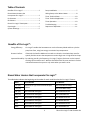
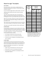
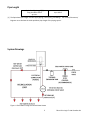
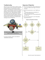
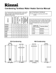
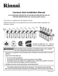
Rinnai Circ-Logic™ With Grundfos GTK15 Kit Description Rinnai Circ-Logic™ offers homeowners enhanced convenience and energy efficiency in home hot water recirculation systems with a dedicated return line. CircLogic™ controls the on/off sequence and operational cycles of the recirculation pump through the programming of the tankless water heater's control board. This feature is standard on Rinnai's Ultra and Luxury Series units. Circ-Logic™ has been designed to provide homeowners with the ability to customize their recirculation systems based on such key variables as length of recirculation loop, piping insulation, and the homeowner's comfort and efficiency preferences. The GTK15 kit, manufactured by Grundfos, allows the user to enjoy further energy savings through the use of a timer. For specific information on warranty with circulation, please visit http://www.rinnai.us/warranty 100000284 Rev D 1 Rinnai Circ-Logic™ with Grundfos Kit Table of Contents Benefits of Circ-Logic™ ...................................... 2 Pump Installation ............................................... 7 Rinnai Water Heaters that Incorporate Circ-Logic™ ..................................... 2 Wiring Pump to the Water Heater ..................... 8 Kit Contents ....................................................... 3 Timer Technical Application .............................10 Disclaimers ......................................................... 3 Timer Operation ...............................................10 Rinnai Circ-Logic™ Description .......................... 4 Troubleshooting ...............................................11 Pipe Length ........................................................ 5 Sequence of Operation ....................................11 Timer Technical Data........................................10 System Drawings................................................ 5 Benefits of Circ-Logic™: Energy Efficiency: Circ-Logic™ enables the homeowner to use the Economy Mode and thus cycle the pump less often, using less energy to maintain loop temperature. Greater Comfort: If desired, the Comfort Mode can be used to re-heat the circulation loop more frequently and thus ensure the temperature remains high, even in high-heat loss loops. Improved Durability: By reducing overall cycle frequency, Circ-Logic™ helps to limit wear on the internal workings of the tankless unit. With the Grundfos GTK15 kit, wear and tear is further minimized because the system is only active when you want it to be. Rinnai Water Heaters that Incorporate Circ-Logic™ The table below indicates the beginning serial number for each model that has the Circ-Logic™ feature. Model Serial Number Part Number RL75i (VC) Units with an "(A)" on the end of the part number. REU-VC2528FFUD-US(A) RL94i (VC) DB.CA-016788 and higher REU-VC2837FFUD-US RL94e (VC) DC.BA-013335 and higher REU-VC2837WD-US RU98i DB.BA-006175 and higher REU-KB3237FFUD-US RU98e DB.BA-006213 and higher REU-KB3237WD-US RU80i DB.BA-006201 and higher REU-KB2530FFUD-US RU80e DB.BA-006195 and higher REU-KB2530WD-US RL75e (VC) 2 REU-VC2528WD-US(A) Rinnai Circ-Logic™ with Grundfos Kit Kit Contents The GTK15 Kit contains the following: • Grundfos 15-55 pump with timer and internal check valve • 6' electrical cord • 6' BX conduit pre-wired to pump • (5) wire nuts • Flange kit • Rinnai Circ-Logic™ Manual Disclaimers: • Pump must be installed in accordance with Rinnai installation instructions when Circ-Logic™ is used. • This document is intended to be used as a guide only and not as a replacement for a professionally engineered project. The contractor/engineer must determine the necessary components for and configuration of the particular system being installed. This guide does not imply compliance with local or national building codes. It is the engineer’s or contractor’s responsibility to ensure the installation is in accordance with all local building codes. The water heater and the plumbing system should be installed in accordance with local codes and with Rinnai installation manual. 3 Rinnai Circ-Logic™ with Grundfos Kit Rinnai Circ-Logic™ Description How It Works DIP switches (SW2 - white switches, #4, #8) should be set correctly for recirculation and mode. The Rinnai water heater should be turned on. Pump recirculation begins when the water heater is turned on. The Rinnai inlet and outlet thermistors measure the water temperature. The water heater produces hot water at the temperature setting. If the inlet thermistor detects abnormal temperature then diagnostic code 51 is generated and the pump will turn off. When the return water temperature reaches approximately 15° F (8.3°C) below the temperature setting, the water heater and pump will turn off. The cycle will start at the approximate time interval in the table. The cycle stops based on the temperature thermistor readings. The Logic has two modes of operation: Comfort and Economy. Economy Mode Economy Mode uses longer time intervals (about twice as long as Comfort Mode) and can be used for two purposes: to reduce the energy consumption required to keep the loop warm and/or to maintain temperature in a loop that is well insulated. Economy Mode operates as follows: Less energy consumed due to fewer pump cycles Pump cycles on every 31 to 79 minutes (see table) The time intervals are based on the assumption that the loop is insulated. Rinnai Temperature Setting °F Typical Pump ON Intervals* (minutes) Economy Mode Comfort Mode 140 31 15 135 31 15 130 31 15 125 31 15 120 31 15 115 35 18 110 42 21 108 45 22 106 49 24 104 54 27 102 60 30 100 68 34 98 79 39 * The pump will cycle on at these calculated intervals which are based on the temperature setting, insulation, and estimated heat loss in the system. The values for your installation may vary. Comfort Mode Comfort Mode has shorter time intervals and can be used to either ensure the loop is always kept hot or to cope with a loop that has a high degree of heat loss due to lack of insulation, or pipes that run through a concrete slab, etc. Comfort Mode operates as follows: Higher energy consumption due to more pump cycles Pump cycles on every 15 to 39 minutes (see table) The time intervals are based on the assumption that the loop IS NOT insulated. 4 Rinnai Circ-Logic™ with Grundfos Kit Pipe Length Equivalent Pipe Length [1] using Grundfos GTK15 Up to 200 ft @ 120° F [1] The Equivalent Pipe Length includes supply piping, return piping, and fittings. The Installer/Contractor/ Engineer must calculate the total equivalent pipe length of the piping system. System Drawings Figure 1: Recirculation using One Rinnai Water Heater 5 Rinnai Circ-Logic™ with Grundfos Kit GTK15 PUMP Circulating Unit Non-Circulating Unit Figure 2: Recirculation using Two Rinnai Water Heaters 6 Rinnai Circ-Logic™ with Grundfos Kit Pump Installation A licensed professional must install the GTK15 kit. It is recommended that isolation valves be installed on each side of the pump. If possible, do not install elbows, branch tees, and similar fittings just before or after the pump. Provide support to the pump or adjacent plumbing to reduce thermal and mechanical stress on the pump. The installer should have skills such as connecting gas lines, water lines, valves, and electricity knowledge of applicable national, state, and local codes Installation If you lack these skills, contact a licensed professional. 1. Thoroughly clean and flush the system prior to pump installation. The pump supplied with your GTK15 kit is meant for indoor installations only. It is designed to circulate 2. Do not install the pump at the lowest point of the water from 36°F to 150°F up to a maximum pressure of system where dirt and sediment naturally collect. 145 PSI. 3. Install an air vent at the high point(s) of the system The proper operating voltage and other electrical to remove accumulated air. information can be found on the nameplate attached 4. Ensure that water does not enter the terminal box to the top of the motor. during the installation process. Position of terminal box: 5. Install the pump as shown on the system drawings; Proper installation of the pump will have the terminal the suction side of the pump should be flooded box located to one side of the pump or the other, with with water. the conduit entry down. See Figure 3A. 6. DO NOT START THE PUMP UNTIL THE SYSTEM HAS BEEN FILLED AND CHECKED FOR LEAKS OR OTHER POSSIBLE COMPONENT FAILURES. The arrows on the side or bottom of the pump housing indicate direction of flow through the pump. GRUNDFOS circulators can be installed in both vertical and horizontal lines. The pump must be installed with the motor shaft positioned horizontally. Under no circumstances should the pump be installed with the shaft vertical or where the shaft falls below the horizontal plane. See Figure 3B. 7 Rinnai Circ-Logic™ with Grundfos Kit Wiring the Pump to the Water Heater WARNING Installation 1. Turn off the electrical power supply by unplugging the power cord or by turning off the electricity at the circuit breaker. Install the Rinnai water heater according to the Rinnai Installation and Operation Manual. The water heater must be electrically grounded in accordance with local codes and ordinances or, in the absence of local codes, in accordance with the National Electrical Code, ANSI/NFPA No. 70. 2. Install the GTK15 pump according to the System Drawings and Pump Installation instructions. 3. Re-route the water heater power cord or wiring from the smaller access hole to the larger access hole as shown in Figure 4: Bottom of Water Heater. Indoor water heaters are equipped with a threeprong (grounding) plug for your protection against shock hazard and should be plugged directly into a properly grounded three-prong receptacle. Do not cut or remove the grounding terminal from this plug. 4. Route the line cord (power cord) for the GTK15 through this larger access hole. 5. On VC series models, use a knockout or step drill bit to enlarge the smaller hole to 3/4 inch diameter. On KB series models the hole is already the correct size. Attach the conduit from the GTK15 to the smaller access hole using the connector supplied. To protect yourself from harm, before installation: • • • Turn off the electrical power supply by unplugging the power cord or by turning off the electricity at the circuit breaker. (The temperature controller does not control the electrical power.) Turn off the gas at the manual gas valve, usually located immediately below the water heater. 6. Splice the brown, gray, and green wires from the Grundfos unit to the line cord (black, white, green) according to the wiring table. These splices should be located inside the water heater cabinet. Refer to Figure 5: Electrical Diagram. Turn off the incoming water supply. This can be done by turning off the water supply to the building. 7. The wire harness for the recirculation pump is bundled with the wire harness from the PC board. The connector has a black and white wire with the label “Cut wire to connect to pump”. To connect to the pump, cut the connector and splice the wires according to the wiring table and Figure 5. Follow Electrical Code and pump manufacturers recommendations. The Rinnai water heater has the ability to control a recirculation pump. Two modes are available, Economy and Comfort, which recirculate the water in the plumbing system to provide hot water more quickly when a tap is opened. 8. Adjust the dip switch in the water heater by moving the 4th switch in the white set of switches (SW2) to ON. For Economy Mode, set the 8th switch in the white set of switches (SW2) to OFF (default). For Comfort Mode, set the 8th switch in the white set of switches (SW2) to ON. Recirculation mode is for residential installations only. Recirculation mode cannot be used with the Bath Fill controller (BC-100V), or with an air handler. Settings for SW2 (bank of white switches) The maximum Rinnai temperature setting while in recirculation mode is 140°F (60°C). 8 Switch 4 Switch 8 Economy Mode ON OFF Comfort Mode ON ON Rinnai Circ-Logic™ with Grundfos Kit 9. Connect power to the water heater and the GTK15 line cord. 10. Set the timer switch to the actual time by turning the programming ring in the direction of the arrow until the timing arrow points to the actual time on the ring. 11. Set the manual switch to “ON”. Figure 5: Electrical Diagram 12. Press the Power button on the controller. The pump and water heater will turn on to raise the recirculation loop temperature. 13. Refer to the Timer Operation section for additional information on programming the timers. Figure 4: Bottom of water heater FRONT OF WATER HEATER POWER CORDS FOR WATER HEATER AND GTK15 CABLE ACCESS HOLES CONDUIT TO GTK15 Wiring Table Description GTK15 (Timer) Supplied Line Cord +115VAC Brown (Br) Black (Bk) Neutral Gray (Gy) White (W) Ground Green (Gn) Green (Gn) GTK15 (Pump) Rinnai Circ-Logic™ +115VAC (Circ-Logic™) Red (R) Black (Bk) Neutral (Circ-Logic™) Blue (Bl) White (W) WARNING RISK OF ELECTRIC SHOCK The Grundfos GTK15 Pump has two power sources. Disconnect all supply connections before servicing. One is directly from the electrical outlet for the timer and the other is through the water heater for the pump. 9 Rinnai Circ-Logic™ with Grundfos Kit Figure 6B Timer Technical Data ON-Tabs pushed away from center TIMER CONTROL Supply Voltage: 115-120 VAC, 60 hertz Ambient Temperature: -4°F to 175°F OFF-Tabs pushed towards center Shortest Switching Interval: 15 minute increment Switch Modes: “Timer”, “ON” Override, “OFF” Override Protection: Clear plastic cover for dust and moisture protection of the clock face. Timer Speed: Default is High and should be remain at High for Circ-Logic™ 1. Set the timer switch to the actual time by turning the programming ring in the direction of the arrow until the timing arrow points to the actual time on the ring. Timer Technical Application The timer control is designed to turn the circulator on and off at preset times, allowing the user to select operation of the circulator during high use periods of the day. 2. Set the required “ON”/”OFF” times on the programming ring by pushing the programming tabs either away from or toward the center of the ring. Tabs pushed away from the center indicate the circulator is switched ”ON” while tabs pushed toward the center indicate the circulator is switched “OFF”. (See Figure 6B) The pump will only circulate water when both the timer and the Circ-Logic™ output are activated. Timer Operation Setting and operating the timer control and starting the pump: 3. Set the manual switch to the “TIMER” position. The circulator will now start/stop according to the settings of the programming tabs. NOTE: Before the circulator is started, the system must 4. For continuous operation, set the manual switch to be filled with liquid and vented. the “ON” position. To switch the circulator off, set Programming Ring the manual switch to the “OFF” position. The Figure 6A “ON”/”OFF” modes may be used without affecting the function of either the programming ring or the timer switch. Note that the circulator is controlled by both the Timer and the Circ-Logic™ output. Please see the “Sequence of Operation” section for more details. Manual Switch 5. In case of power outage the timer will not keep Timing Arrow time. After power has been restored, the correct time of day must be reset by rotating the programming ring in the direction of the arrow until the timing arrow points to the actual time on the ring. Programming Tabs 10 Rinnai Circ-Logic™ with Grundfos Kit Troubleshooting Sequence of Operation When the pump is first started, the shaft may rotate slowly until water has fully penetrated the bearings. If the pump does not run, the shaft can be rotated manually. To accomplish this, switch off the electrical supply, and close the isolation valves on each side of the pump. Remove the large screw in the middle of the nameplate. Insert a small flat blade screwdriver into the end of the shaft, and gently turn until the shaft moves freely (see Figure 8). Replace and tighten the plug. Open the isolation valves and wait 2 to 3 minutes for the system pressure to equalize before starting the pump. (See Figure 8) A. When the manual switch of the Grundfos timer is in the “ON “ position, the Cir-Logic™ will control the pump. B. When the manual switch is in the “TIMER” position: - if the timer output relay is activated the CirLogic™ will control the pump. - if the timer output relay is deactivated the pump will remain off. C. When the manual switch is in the “OFF position the pump will not run. Sequence of Operations Flowchart Figure 8 NOTE The isolation valves are to be field supplied. This image is just for illustration purposes only. For technical assistance, please contact Rinnai at 1-866-RINNAI1 (746-6241). 11 Rinnai Circ-Logic™ with Grundfos Kit L-UP-TL-R04 100000284 Rev D 12 Rinnai Circ-Logic™ with Grundfos Kit