1
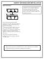
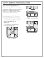
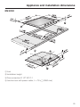
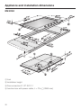
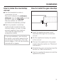
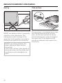
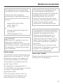
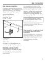
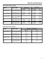
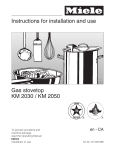
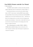
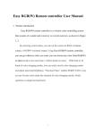
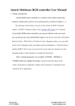
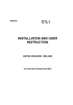
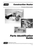
Installation Instructions
KM2030
en-CA
IMPORTANT: SAVE FOR THE LOCAL ELECTRICAL INSPECTOR'S USE
To prevent accidents and machine damage read these instructions before installation or use.
Installation, repair and maintenance work should be performed by a
Miele authorized service technician in accordance with national and
local safety regulations and the provided installation instructions.
SAFETY NOTICES FOR INSTALLATION
To avoid damage to the appliance, it
should not be installed until the
upper cabinet and exhaust hood
have already been mounted.
~ This appliance is not connected to
an exhaust vent. It must be installed
and connected to the power supply in
compliance with the applicable
installation requirements.
~ The room will need to be at least 20
m3 in volume, with at least one door or
window opening to the outside.
~ The countertop veneers must be
affixed with heat-resistant glue
(100 °C), so that they do not become
deformed or detached.
The wall strips must be heat-resistant
as well.
~ Installation and assembly of this
appliance in non-stationary locations
(for example, aboard ships) should be
performed only by specialized
companies/technicians, to ensure that
the requirements for safe use are met.
~ Because there is the risk of
flameover, a gas cooktop should
NEVER be installed next to a
deep-fryer. A minimum distance of 12"
(300 mm) must be maintained between
these appliances. Other appliances
may be build in directly next to the gas
cooktop.
26
~ Storage cabinets above the cooktop
present a fire hazard.
~ This gas cooktop is not authorized
for installation atop
refigerators/freezers, dishwashers, or
washers/dryers.
~ Check to be sure that the gas line
and power cord will not come into
contact with any hot spots after
installation. Hot spots can cause heat
damage to the gas line and power
cord.
~ The power cord and a flexible gas
line must be arranged in such a way
that they will not come into contact with
moveable parts in the cabinetry (e.g., a
drawer) or be subject to any
mechanical strain.
~ Be sure to carefully observe the
clearance distances listed on the
following pages.
~ Never use caulking unless it is
explicitly called for in the instructions.
The sealing tape for the appliance
provides an adequate seal with the
countertop (see the section on "General
installation notices").
SAFETY NOTICES FOR INSTALLATION
Upper clearance
If there are various appliances with
different recommended clearance
distances beneath the exhaust
hood, e. g., a gas stovetop and an
electric cooktop, always choose the
greatest distance.
For an exhaust hood above the
appliance, the safe clearance distance
indicated by the hood manufacturer
must be maintained.
If there are no specifications from the
hood manufacturer or if flammable
materials (e. g., a hanging cabinet) are
installed above the appliance, the
clearance distance must be at least 30"
(760 mm).
The maximum depth of cabinets
installed above the cooktop must be
13" (330 mm).
Miele appliances can be installed flush or proud. Discuss your installation
requirements with you architect, designer and installer.
27
SAFETY NOTICES FOR INSTALLATION
When installing a gas stovetop, the
cabinetry or walls to ONE side and to
the rear of the appliance can be as tall
as you wish. However, on the other side
there must not be any appliance or
furniture that is taller than the installed
gas stovetop (see illustrations).
You must ensure that the following
minimum safety clearances are kept:
– 4" (100 mm) to the right or left of the
countertop cut-out to the next closest
piece of furniture (e.g., tall
cupboard).
2”
Highly recommended
– 2" (50 mm) from the countertop
cut-out to the rear wall.
Not recommended
Not permitted
28
Appliance and installation dimensions
KM 2030
a front
b Installation height
c Gas connection R 1/2" ISO 7-1
d Junction box with power cable, L = 78 3/4" (2000 mm)
29
Appliance and installation dimensions
KM 2050
a front
b Installation height
c Gas connection R 1/2" ISO 7-1
d Junction box with power cable, L = 78 3/4" (2000 mm)
30
Installation
How to make the countertop
cut-out
How to install the gas stovetop
^ Use the template to make a
countertop cut-out.
Be sure to observe the minimum
distance from the rear wall and from
the left or right to a side wall.
See the section on "SAFETY
NOTICES FOR INSTALLATION".
^ Seal any wooden countertop
surfaces with a special varnish,
silicone rubber, or resin, to help
prevent swelling from moisture.
The materials used must be
temepature-stable.
If, during installation, you find that
the frame is not tightly sealed to the
countertop at the corners, then the
corner edges, ß R4, can be carefully
trimmed with a jigsaw.
^ Feed the appliance power cord
downward through the countertop
cut-out.
^ Set the appliance loosely into place
in the cut-out.
^ Connect the appliance to the power
supply (see the section on "Electrical
connection").
^ Establish the gas connection (see the
section on "Gas connection").
^ Use the supplied brackets to hold the
appliance in place.
31
General installation information
Sealing
Tiled surfaces
NEVER use sealing unless it is explicitly
called for in the instructions. The
sealing strip under the edge of the
upper part of the appliance provides a
sufficient seal against the countertop.
The grouting a and shaded area under
the cooktop frame must be flat and
even, so that the frame will lie evenly
and the sealing strip under the edge of
the upper part of the appliance can
provide an adequate seal against the
countertop.
NEVER use sealing between the
upper appliance frame and the
countertop!
It will hinder access to the appliance
during servicing, and the frame and
countertop can be damaged as a
result.
32
Electrical connection
This appliance must be grounded
according to local or national codes.
All electrical work should be
performed by a qualified electrician
in accordance with local codes and
with the:
-
National Electrical Code
ANSI / NFPA 70
for the USA
or
- Canadian Electrical Code Part I
for Canada
(CSA Standard C 22.1)
,WARNING
Disconnect the appliance from the
main power supply before
installation or service. To reduce the
risk of electric shock, make sure that
the appliance is properly grounded
after installation.
This appliance is equipped with a
three-prong grounding plug to
prevent shock hazards. It should be
plugged directly into a properly
grounded outlet. Do not cut or
remove the grounding prong from
the plug. If the plug does not fit the
outlet, have the proper outlet
installed by a licensed electrician.
To guarantee the electrical safety of
this appliance, continuity must exist
between the appliance and an
effective grounding system. It is
imperative that this basic safety
requirement be met. If there is any
doubt, have the electrical system of
the house checked by a qualified
electrician.
The manufacturer cannot be held
responsible for damages caused by
the lack, or inadequacy, of an
effective grounding system.
Power supply
The automatic ignition requires that the
appliance be connected to a 120 VAC,
60 Hz power supply. The supply line
should be protected by a 15 A fuse.
Note to the installer
Please leave these instructions with the
consumer or the appliance.
Actual power consumption (during
ignition only) is 25 W.
This appliance is equipped with a
78 3/4" (2000 mm) long power cord that
is ready for connection to the
appropriate outlet.
Place the power outlet so that it is
accessible after the appliance has
been installed in the countertop.
33
Gas connection
Installation and service must be
performed by a qualified installer,
service agency or the gas supplier.
The gas connection must be made
in accordance with local codes or, in
the absence of local codes, with
This appliance must be installed
with its own shut off valve and the
included gas pressure regulator.
Both the valve and the regulator
must be easily accessible to the
consumer to turn on or shut off the
gas supply after the appliance is
installed.
-
This appliance and its individual
shut off valve must be disconnected
from the gas supply during any
pressure testing performed in
excess of ½ psi (3.5 kPa), or
isolated from the gas line by closing
its individual manual shut off valve at
test pressures equal to or less than
½ psi (3.5 kPa).
Any pipe connections must be made
using a thread sealant approved for
gas connections. Failure to correctly
install these items could lead to a
gas leak and subsequent explosion.
Leak testing of the appliance shall
be conducted according to the
manufacturer's instructions.
34
the National Fuel Gas Code,
ANSI Z 223.1/NFPA 54
for the USA
or
- the current Can/CGA B 149.1
and .2 Installation Codes for gas
burning appliances for Canada.
Make sure that the maximum gas
supply pressure before the gas
pressure regulator is never more than
½ psi for both natural gas or LP gas.
The minimum supply pressure to get
the required gas input is
4" w.c. for natural gas:
10" w.c. for LP gas.
Gas connection
Gas pressure regulator
A pressure regulator that is convertible
from natural to LP gas (Propane) or vice
versa is included with the appliance.
The included regulator corresponds
with the gas type of the appliance.
Verify before installing.
The adjusted pressure is:
natural gas - 4" w.c.
LP gas - 10" w.c.
For convenience, an AGA or CGA
approved flexible stainless steel gas
hose (accordion type) may be used
between the gas connection and the
regulator. This will allow the appliance
to be lifted out of the countertop for
cleaning or servicing. Make sure that
any drawers, cabinet doors, etc., do not
rub on this gas hose.
Do not use any regulator unless it
has been supplied by Miele. Doing
so may cause a gas leak.
If there is any doubt concerning
installation contact the Miele Technical
Service Department.
After connecting the appliance check
all fittings for gas leaks e.g. with
soapy water.
a Appliance
b ½" NPT
When installed properly, the flame will
be steady and quiet. It will also have a
sharp, blue inner core that will vary in
length proportional to the burner size.
Flame adjustment will not be
necessary.
c Regulator
As shown in the above diagram, the
included regulator must be used when
connecting the Miele appliance to your
gas supply. This item has been
customized by Miele to meet all
applicable safety requirements. Make
sure the regulator is easily accessible
for adjustment after the appliance has
been installed.
35
Gas connection
The appliance should have been
ordered for connection to either natural
gas or LP gas (propane).
If the appliance is not configured for the
proper type of gas connection please
contact your Miele Dealer.
If the appliance is to be connected to a
type of gas other than it was originally
configured for, both the regulator and
burners must be converted. A
conversion kit is available as an
optional accessory from the Miele
Technical Service Department.
36
Burner performance
Rated load at high setting
Burner
Type of gas
KM 2030
KM 2050
BTU/hr
kW
BTU/hr
kW
Small burner
Natural gas (NG)
Liquid gas (LP)
3500
3500
1,00
1,00
3500
3500
1,00
1,00
Regular burner
Natural gas (NG)
Liquid gas (LP)
6200
5800
1,80
1,70
6200
5800
1,80
1,70
Power burner
Natural gas (NG)
Liquid gas (LP)
-
-
8900
8900
2,60
2,60
Wok
Natural gas (NG)
Liquid gas (LP)
12000
11000
3,50
3,20
12000
11000
3,50
3,20
Total
Natural gas (NG)
Liquid gas (LP)
27900
26100
8,10
7,60
36800
35000
10,70
10,20
Rated load at low setting
Burner
Type of gas
KM 2030 / KM 2050
BTU/h
kW
Small burner
Natural gas (NG)
Liquid gas (LP)
850
850
0,25
0,25
Regular burner
Natural gas (NG)
Liquid gas (LP)
1200
1200
0,35
0,35
Power burner
Natural gas (NG)
Liquid gas (LP)
1700
2000
0,50
0,60
Wok
Natural gas (NG)
Liquid gas (LP)
3700
3700
1,10
1,10
37
How to switch to a different gas type
,Switchover to a different gas type should only be performed by a duly
authorized gas company technician.
Save the nozzles removed from the appliance for future use.
Nozzle table
If you switch to a different type of gas, the large and small burner nozzles will
need to be changed.
Main nozzle Ø
Low setting nozzle Ø
0,90
1,13
1,45
1,63
0,42
0,52
0,60
1,30 (1A)
0,58
0,72
0,90
0,98
0,27
0,32
0,40
0,60
Natural gas (NG)
Small burner
Regular burner
Power burrner
Wok
Liquid gas (LP)
Small burner
Regular burner
Power burrner
Wok
The nozzle listings are for a 1/100mm bore diameter.
38
How to switch to a different gas type
How to change a nozzle
Small, normal, and power burners
Unplug the appliance from the
electrical supply.
How to change the main nozzle
^ Remove the burner cover b, the
burner ring a (wok) and the burner
head c.
^ Use a socket wrench (M7) to
unscrew the main nozzle h.
^ Insert the proper nozzles (see Nozzle
table) and tighten them down.
Wok burner
39
How to switch to a different gas type
How to change the small nozzles
(all burners)
To change the small nozzles, you will
first need to remove the upper part of
the appliance.
a
^ Unscrew the mounting screws on the
burner.
^ Pull the control knob up and off.
^ Take off the upper part of the
appliance.
^ Remove the ignition switch a.
^ Use a small screwdriver to unscrew
the small nozzle b from the gas tap.
^ Use needle-nosed pliers to pull the
nozzle out.
^ Insert the proper nozzles (see Nozzle
table) and tighten them down.
40
b
How to switch to a different gas type
After switching over
^ Use the reverse order to re-assemble
the burner parts.
^ Before putting the upper part of the
appliance back in place, light each
burner with matches to test the seal
on all the gas flow parts.
^ After testing, set aside the loose
burner parts.
^ Put the upper part of the appliance
back in place.
^ Screw down the lower part of the
burner, then put the loose burner
parts back into place, making sure to
follow the right order.
^ Put the control knob back on.
^ Finally, check the flame behaviour of
each burner.
The flame must not go out in the low
setting, even if the control knob is
quickly turned from "high" to "low".
At the high setting, the flame needs to
burn with a clearly visible core.
^ In the nozzle pack, find the
appropriate sticker for the new gas
type and stick it over top of the
previous sticker.
41
Alteration rights reserved / 4908
For the most updated manual see the Miele web site.
M.-Nr. 07 520 080 / 00