1
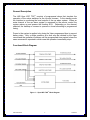
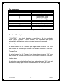
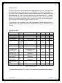
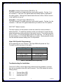
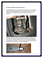
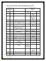
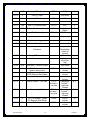
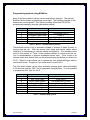
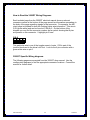
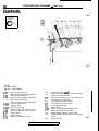
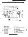
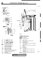
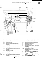
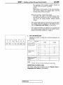
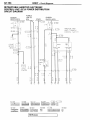
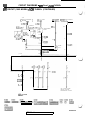
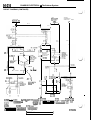
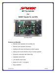
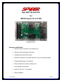
Viper WIFI Top Controller
For
3000GT Spyder SL and VR4
Actual Size Shown
Features and Benefits
•
Remote control operation of convertible roof
•
Remote control operation of tonneau
•
Interfaces with Viper 590x series
•
Pause and continue or reverse direction of top or tonneau operation
•
Programmable open / close timers
•
Relay Isolated from other car electronics
•
Low standby current drain
•
Small 2.6 x 4.25 x 1.12 footprint
•
Easy installation
JNS Engineering
1
3/18/2013
Table of Contents
General Description ....................................................................................... 3
Functional Block Diagram .............................................................................. 3
Pin Assignment .............................................................................................. 4
Functional Description ................................................................................... 4
Specifications................................................................................................. 5
PCB Layout................................................................................................... 6
Installation Instructions .................................................................................. 7
Wiring Color Codes (WIFI TOP™ Harness) .................................................... 7
Wiring the Harness ........................................................................................ 8
Viper 5904 Specific Programming ................................................................. 9
Troubleshooting the Installation ..................................................................... 9
Remote Top Testing .................................................................................... 10
Remote Start Neutral Safety Switch ............................................................ 11
Remote Start Neutral Safety Circuit ............................................................. 11
Installing the Magnetic Switch and Magnet .................................................. 12
Installing the Viper 5904 / Python 594 / Clifford 590.4x Alarm ..................... 13
Viper 5904/ Python 594 / Clifford 590.4X Wiring for 3000GT ...................... 15
Wiring Color Codes (Viper 5904/ Python 594/ Clifford 590.4X Alarm) ......... 18
Programming options using BitWriter .......................................................... 19
How to Read the 3000GT Wiring Diagrams ................................................. 20
3000GT Specific Wiring diagrams ............................................................... 20
Table of Tables
Table 1 – Pin Assignment .............................................................................. 4
Table 2 – Specifications ................................................................................. 5
Table 3 – WIFI TOP™ Harness ...................................................................... 7
Table 4 – Viper 5904 Specific Programming.................................................. 9
Table 5 – Viper 5904/ Python 594/ Clifford 590.4X Wiring for 3000GT ........ 17
Table 6 – Menu 3 – Remote Start Parameters ............................................ 19
Table 7 – BitWriter Only Options ................................................................. 19
Table of Figures
Figure 1 – Viper WIFI TOP™ Block Diagram .................................................. 3
Figure 2 – PCB Top Side Artwork .................................................................. 6
Figure 3 – PCB Bottom Side Artwork ............................................................. 6
Figure 4 – Domelight Relay ......................................................................... 17
JNS Engineering
2
3/18/2013
General Description
The JNS Viper WIFI TOP™ consists of programmed relays that simulate the
operation of the rocker switches for the top and tonneau. In the standby mode
the Interface is monitoring the level outputs of the car alarm system. When an
extra channel of the car alarm system is accessed by the remote control the
system wakes up and powers the Hardtop ECU. Depending on the channel
selected, the hardtop or tonneau is opened or closed according to programmed
timing.
Power to the system is applied only during the Viper programmed time to prevent
battery drain. Only a single operation at a time may be initiated by the Viper
remote and the operation continues until the programmed time expires unless the
same command is repeated in which case the operation immediately stops.
Functional Block Diagram
™
Figure 1 – Viper WIFI TOP Block Diagram
JNS Engineering
3
3/18/2013
Pin Assignment
DB25 PIN
1
2
5
6
7
8
10
11
12
13
14
DESCRIPTION
+12V (Battery)
Gnd
Tonneau Open Trigger
Hardtop Close Trigger
Tonneau Close Trigger
Hardtop Open Trigger
Tonneau Open Actuator
Tonneau Close Actuator
Hardtop Open Actuator
Hardtop Close Actuator
+12V (Ign2)
Table 1 – Pin Assignment
Functional Description
***CAUTION*** Care should be taken to stand clear of the top mechanism
during remote activation.
Once activated, the mechanism will operate
automatically until the timers expire or the same command is repeated.
Tonneau Open
An active low level on the Tonneau Open trigger places the car in “ON” mode
and actuates the Tonneau Open function for the duration of the Aux1 Viper timer.
Tonneau Close
An active low level on the Tonneau Close trigger places the car in “ON” mode
and actuates the Tonneau Close function for the duration of the Aux2 Viper timer.
Hardtop Open
An active low level on the Hardtop Open trigger places the car in “ON” mode and
actuates the Hardtop Open function for the duration of the Aux4 Viper timer.
JNS Engineering
4
3/18/2013
Hardtop Close
An active low level on the Hardtop Close trigger places the car in “ON” mode and
actuates the Hardtop Close function for the duration of the Aux3 Viper timer. If
the safety stop is reached during Hardtop closure then the Hardtop will stop
movement and the “ON” mode will remain active until Aux3 times out. A second
press of the Aux3 function will complete the Hardtop closure. If the second press
occurs at the safety stop while Aux 3 is active then Aux3 will terminate and a
third press will immediately complete Hardtop closure.
If the safety stop is removed (see JNS Engineering TopLink manual) then a
single press of the Aux3 function can complete the closure if the timer is long
enough.
Specifications
Parameter
Input voltage
Input current
Trigger voltage
Sink current
Output voltage
Source current
Source current
Tonneau open
time (Aux 1)
Tonneau close
time (Aux 2)
Hardtop open
time (Aux 4)
Hardtop close
time (Aux 3)
System active
time
Pin
1
1
5,6,7,8
5,6,7,8
10,11,
12,13,
14
14
10,11,
12,13
Test conditions
Active trigger
Active
12
Units
V
mA
V
mA
V
Active
Active
20
20
A
A
Programmed using
BitWriter
Programmed using
BitWriter
Programmed using
BitWriter
Programmed using
BitWriter
10
S
10
S
32
S
40
S
1
S
Standby
Min
Typical
12
5
Max
4
5
Table 2 – Specifications
1
System remains active (“ON” mode) for the duration of the selected Aux function
JNS Engineering
5
3/18/2013
PCB Layout
Figure 2 – PCB Top Side Artwork
Figure 3 – PCB Bottom Side Artwork
JNS Engineering
6
3/18/2013
Installation Instructions
WIFI TOP™ Interface Harness
SOURCE
DB 25
Color
PIN
1
R
Description
+12V (Battery)
DESTINATION
Connector
Color
- Pin
C59-6
W
2
B
Gnd
Chassis
B
5
W
Tonneau Open Trigger
White-Violet Wire 1
6
Y
Hardtop Close Trigger
White-Black Wire 1
7
O
Tonneau Close Trigger
Violet-Black Wire 1
8
G
Hardtop Open Trigger
Orange-Black Wire 1
10
L
Tonneau Open Actuator
D48-10
LG-B 2
11
P
Tonneau Close Actuator
D48-9
B-W
12
BR
Hardtop Open Actuator
D48-3
13
GR
Hardtop Close Actuator
D48-11
L-W
14
CL
+12V (Ign2)
D48-4
R
2
GR-R 2
2
™
Table 3 – WIFI TOP Harness
Wiring Color Codes (WIFI TOP™ Harness)
W
B
LG-B
B-W
GR-R
L-W
BR
CL
=
=
=
=
=
=
=
=
White
Black
Light Green with Black stripe
Black with White stripe
Grey with Red stripe
Blue with White stripe
Brown
Clear
R
Y
O
G
L
P
GR
=
=
=
=
=
=
=
Red
Yellow
Orange
Green
Blue
Purple
Grey
1
Wire colors from the Viper 5904 extra channels. These will be different if you
use another car alarm system.
2
Wire colors from the 3S manual. They were different colors in my car.
JNS Engineering
7
3/18/2013
Wiring the Harness
Red Wire: +12V Input (DB25 Pin 1)
Connect this wire to the +12VDC constant source found at the ignition harness
connector C59 pin 6 located under the driver side dash. It is the White wire. Use
a fused connection or tie in after the car alarm system fuse.
Black Wire: Gnd (DB25 Pin 2)
Connect this wire to Chassis ground. Remove the driver’s side center console
cover and use one of the relay mounts to attach a ground lug. Make sure the
ground wire is FIRMLY attached to the bare metal surface. Do NOT ground the
car alarm to the same location.
White Wire: Tonneau Open Trigger (DB25 Pin 5)
Connect this wire to the Viper 5904 H2-13 White-Violet wire which is the Aux 1 (-)
200mA output.
Yellow Wire: Hardtop Close Trigger (DB25 Pin 6)
Connect this wire to the Viper 5904 H2-11 White-Black wire which is the Aux 3 (-)
200mA output.
Orange Wire: Tonneau Close Trigger (DB25 Pin 7)
Connect this wire to the Viper 5904 H2-14 Violet-Black wire which is the Aux 2 (-)
200mA output.
Green Wire: Hardtop Open Trigger (DB25 Pin 8)
Connect this wire to the Viper 5904 H2-15 Orange-Black wire which is the Aux 4
(-) 200mA output.
Blue Wire: Tonneau Open Actuator (DB 25 Pin 10)
The D48 connector is located under the control switch garnish. Find pin 10 on
the connector. It will have 12V applied when the tonneau switch is operated to
the open position. Although the manual states this wire is Light Green / Black I
found it to be Green in my car.
Purple Wire: Tonneau Close Actuator (DB 25 Pin 11)
The D48 connector is located under the control switch garnish. Find pin 9 on the
connector. It will have 12V applied when the tonneau switch is operated to the
close position. Although the manual states this wire is Black / White I found it to
be Black in my car.
Brown Wire: Hardtop Open Actuator (DB 25 Pin 12)
The D48 connector is located under the control switch garnish. Find pin 3 on the
connector. It will have 12V applied when the hardtop switch is operated to the
open position. Although the manual states this wire is Grey / Red I found it to be
Yellow in my car.
JNS Engineering
8
3/18/2013
Grey Wire: Hardtop Close Actuator (DB 25 Pin 13)
The D48 connector is located under the control switch garnish. Find pin 11 on
the connector. It will have 12V applied when the hardtop switch is operated to
the close position. Although the manual states this wire is Blue / White I found it
to be Light Blue in my car.
Clear Wire: +12V Ign2 Output (DB 25 Pin 14)
The D48 connector is located under the control switch garnish. Find pin 4 on the
connector. It will have 12V applied when the key is turned to the “On” position.
WIFI TOP™ Module Location
The best locations for the interface module are under the rocker switches or
behind the ECU. To install the interface module you will need to loosen the trim
piece that holds the rocker switches in the center console. The interface module
at 2.6 x 4.25 x 1.12 is small enough to slip into the open slot. You can zip tie it to
the wire harness or use double-sided tape as you prefer. Simply plug the module
into the Interface harness making sure it is fully seated.
Viper 5904 Specific Programming
No programming per se is required. The Viper 5904 will operate the Top /
Tonneau functions as shown in the table
Viper 5904 Key Fob
“Lock”
“Unlock”
“ƒ” + “Aux”
2x “ƒ” + “Aux”
4x “ƒ” + “Aux”
3x “ƒ” + “Aux”
Function
Lock
Unlock
Tonneau Open
Tonneau Close
Hardtop Open
Hardtop Close
Table 4 – Viper 5904 Specific Programming
Troubleshooting the Installation
There are 5 LEDs to assist diagnosing problems with the installation; however
they are not viewable unless the case is opened. The LEDs indicate the active
timing cycle(s).
D2
D5
D11
=
=
=
JNS Engineering
Tonneau Open LED
Tonneau Close LED
Hardtop Open LED
9
3/18/2013
D14
D20
=
=
Hardtop Close LED
IGN2 LED
There are also Test points for each input trigger and ground. These are labeled
as follows:
TP2
TP3
TP4
TP5
TP1
=
=
=
=
=
Tonneau Open Trigger
Hardtop Close Trigger
Tonneau Close Trigger
Hardtop Open Trigger
Ground
The installation can be tested independently from the car alarm system by
manually triggering the timer circuits. To cause a timing cycle to begin, simply
make a solid electrical connection between the appropriate trigger test point and
the ground test point. The system will respond by lighting the appropriate LED
and driving the top mechanism.
When any of the four TPs is triggered, the IGN2 signal will power the car as
though the ignition switch were in the ON position. All electrical systems (such
as Climate Control and Radio) that were running when the car was last turned off
will resume operating until the triggering function expires.
Remote Top Testing
Note these functions will not work correctly until the timed output modes are
enabled using BitWriter.
Key sequences
• Press “ƒ” and then “Aux”. The tonneau should open.
• Press “ƒ” twice and then “Aux”. The tonneau should close.
• Press “ƒ” four times and then “Aux”. The hardtop should open.
• Press “ƒ” three times and then “Aux”. The hardtop should close. If the
hardtop waits at the safety stop repeat the key sequence one or two more
times.
• Press the “Timer” button twice within 3 seconds. The car should remote
start (if equipped and programmed per this guide). All key sequences
listed above will function under Remote Start as well as battery power
only.
The Remote Top Key Sequences WILL NOT initiate any actions if the car is
running normally after being started by the key.
JNS Engineering
10
3/18/2013
Remote Start Neutral Safety Switch
First a disclaimer. Installing a remote start capability in a manual transmission
car is not safe, probably voids the security system warranty, and is possibly
against the law. The author takes no responsibility for any consequences from
the correct or incorrect use of the following information.
Now with that out of the way the author recognizes that many people might be
installing remote start into their MTX 3000GT without hooking up any safety
devices to prevent accidental start while in gear. This instruction, if followed
correctly, will provide an additional measure of safety for remote starting.
Benefits
• Prevents remote starting with the car in gear
Parts Needed
• Magnetic switch
o Normally open type (continuity when the magnet is close)
o Recessed mount type (cylindrical type allows perpendicular mount)
o AMS-21 or equivalent is suggested (about $7 at this site)
o Go here for a datasheet for the part
• Other stuff
o I used RTV and a tie wrap to secure the magnet and switch
o I used T-Taps to connect to existing stock wiring
Remote Start Neutral Safety Circuit
The Viper 590x has a Neutral Safety (-) input that we can wire directly to the
magnetic switch and no relays or other circuits are needed. There is also no
need to unplug the clutch safety switch as we will be wiring the remote start
controls using Marc Mayer’s elegant method of interrupting the stock wiring in a
specific location. With this method the car operates exactly as stock, requiring
the clutch to be depressed for normal starts, and yet remote starts by bypassing
the wiring in a different way. More about this in the Viper 590x install section.
JNS Engineering
11
3/18/2013
Installing the Magnetic Switch and Magnet
I installed the magnetic switch horizontally under the shift arm. It is positioned so
that the magnet will be perpendicular to the switch when the shifter is in neutral.
When in gear, the magnet will be away from the switch and the switch will be
open circuited. I used clear RTV to hold the switch and allowed it to set
overnight
I found that the magnet needs to be installed very low on the shift arm. I have
Bob Stirling’s 3S short shifter which has a flat side suitable for mounting the
magnet. At first I intended to use only a tie wrap, but the magnet was wiggling
out of position so I secured it with RTV as well. The tie wrap is touching the post
that attaches the shift linkage. I also notched the plastic of the magnet so the tie
wrap would bite into the magnet and keep it from slipping.
JNS Engineering
12
3/18/2013
Installing the Viper 5904 / Python 594 / Clifford 590.4x Alarm
The installation manual that comes with these systems covers everything you
need to know so I will just add some suggestions for where to locate things.
The Brain (main unit). Best location to connect to the ignition harness as well as
the remote start wiring seems to be directly behind the glove box in front of the
A/C unit.
The Antenna, Valet Switch & LED. These are a combined plug in module
designed to mount high on the windshield. Wiring can be routed down the
passenger side A pillar.
The Remote Start Disable Toggle / Optional remote start/turbo timer push button.
These can be mounted anywhere convenient. Personally I’m not a big fan of
drilling holes for switches and prefer repurposing OEM switches which aren’t
used in the spyder such as the headlight pop-up switch (under fog light) or a rear
wiper switch.
The Hood Switch. This one is simply not needed if you follow my wiring guide to
wire into the stock hood switch.
The Shock Sensor. This one is built into the 5901 but is external for the 5904
series. If external it can be mounted to the A/C unit behind the glove box.
Adjustable from remote.
Optional Field Disturbance Sensor 508D. This is a great option for convertibles
and has separately adjustable warning and alarm zones. Under the rear seat in
front of the seat belts was a good location. This device works with both 5901 and
5904 however requires external 12V / Gnd powering for the 5904 application.
Bitwriter ESP port. While many features of the alarm system can be
programmed using the valet button, many others need the hand-held
programmer to access. It also makes programming much easier. If you run an
optional bitwriter cable (8998 standard; 8999 molded) to a place easily accessed
later (I put mine under the gearshift boot) – you can change programming easily.
Magnetic Switch. No need for a relay – connect one lead from magnetic switch
to Neutral Safety (-) input of alarm and other lead to ground. Note these alarms
have a manual transmission mode which doesn’t rely on this input, but requires a
rather convoluted procedure to arm remote start. I used the magnetic neutral
safety switch and programmed the alarm as an automatic transmission for more
convenient operation.
JNS Engineering
13
3/18/2013
Defogger. Defogger can be remotely operated or will run automatically during
remote start if temperature is below 55°F. In this setup, a pulsed output should
be programmed.
Locks. Instructions provide for 1st remote unlock unlocks drivers door only; 2nd
unlock unlocks passenger door – as with stock remote entry. Involves
connecting to the Keyless Entry Control Unit Located near left rear speaker
(behind panel). See note 1 in the wiring instructions for 1st remote unlock
unlocks both doors.
Factory Alarm. While it’s possible to set up the system to arm/disarm the factory
alarm when locking/unlocking the doors remotely, it involves the use of several
relays and diodes and is frankly not worth the effort required.
Clutch Switch. By installing the alarm’s starter wiring as directed, there is no
need to remove, disable or bypass the clutch switch which is also used by the
cruise control. It will continue to function normally when using the key to start the
car.
Starter connection. The alarm features anti-grind relay which prevents the key
from running the starter when the remote start feature is active. This involves
cutting one of the starter wires – the key side is connected to one lead and the
car (starter relay) side is connected to another lead. The recommended place to
make this cut is inconveniently located - connector is in upper right hand corner
of passenger footwell, but by using this location there is no need to bypass the
clutch pedal switch.
The Siren Options are limited due to size. I zip tied mine to the cross bar under
the bumper where the horns are located. It can also go inside the driver’s wheel
well if you remove the fender liner.
Positive Light Flash Output The brain box has a removable cover which covers a
jumper block. Set the jumper to Positive Light Flash Output to be compatible
with the 3000GT parking light circuit polarity.
Wire Lengths Some of the Viper 590x wires are not long enough to reach the
recommended destinations and will have to be extended. If the behind glove box
location is used for the brain the following wires will have to be extended:
H1-5
H2-3
H2-7
H2-8
Parking light output
Defogger (-) 200mA output
Domelight 200mA (-) output
Horn honk (-) output
JNS Engineering
14
3/18/2013
Viper 5904/ Python 594 / Clifford 590.4X Wiring for 3000GT
SOURCE
DESTINATION
5904/594/590.
3000GT
4X
Harne Color
Description
Connector
Location
ss
- Pin
H1-1
R
Battery 12V Source (fused)
C59-6
Left of
column
H1-2
B
Chassis Ground
Use ground
lug. Do not
share with
WIFI
H1-3
BR
Siren (+) Output
Siren
H1-4
W-BR
H1-5
W
H1-6
O
D-1
L
Ground when Armed (also
during remote start if antigrind option used)
Door unlock (-)
D-3
G
Door Lock (-)
H2-1
P-W
IGN2 (-) 200ma output
(not used)
H2-2
B-W
Neutral Safety (-) input
H2-3
L-W
Defogger (-) 200mA output
Magnetic
switch
ETACS unit
H2-4
G-B
OEM disarm (-) 200mA out
(not used)
H2-5
R-W
(not used)
H2-6
G
Aux trunk release (-)
200mA
Door (-) input
H2-7
B-Y
Domelight 200mA (-)
output
H2-8
BR-B
Horn honk (-) output
H2-9
L
H2-10
P
JNS Engineering
Flex Parking Light Relay
87A
Parking light output (10A)
Color
W
R
(not used)
C69-6
Junction
Block
(not used)
G-W
E37-14
(Note 1)
C66-56
Keyless
Entry Unit
ETACS unit
Y-B
C65-12
BR-W
L-R
C65-10
ETACS unit
R-G
C65-9
(use relay)
See figure
4
C57-2
ETACS unit
R-G
L-G
Status (-) 200ma out
Clock Spring
(right of
column)
(not used)
IGN1 (-) 200ma output
(not used)
15
3/18/2013
H2-11
W-B
Aux 3 (-) 200mA output
WIFI-6
WIFI
Y
H2-12
V
Door (+) Input
H2-13
W-V
Aux 1 (-) 200mA output
WIFI-5
WIFI
W
H2-14
V-B
Aux 2 (-) 200mA output
WIFI-7
WIFI
O
H2-15
O-B
Aux 4 (-) 200mA output
WIFI-8
WIFI
G
H2-16
BR
Brake shut down (+) input
C61-3
G
H2-17
GR
Hood Pin Switch (-) input
C65-18
Brake Pedal
Switch
ETACS unit
H2-18
V-Y
Starter (-) 200ma out
(not used)
H2-19
L
Trunk instant trigger (-)
(not used)
H2-20
GR-B
Wait to Start (-) input
(not used)
H2-21
W-L
Remote Start-Turbo Timer
Activation
H2-22
O
Acc (-) 200ma output
Optional
Momentary
switch to
ground
(not used)
H2-23
V-W
Tachometer Input
H2-24
G-W
OEM arm (-) 200mA output
H3-1
P
H3-2
R-W
H3-3
(not used)
L-B
C90-58
ECU (2nd
plug from
top)
(not used)
W
C59-4
H3-4
V
Starter Output – Car Side
C31-2
Cut wire –
car side
H3-5
G
Starter – Key Side
C31-2 –
cut wire –
key side
H3-6
R
C59-6
H3-7
P-W
12V (+) constant – feeds
IG1 Remote Start Relay
IGN2 Output
Left of
column
Left of
column
Left of
column
Passenger
footwell –
right side
firewall
Passenger
footwell –
right side
firewall
Left of
column
Left of
column
B-W
O
IGN1 Output – Also
ignition sense input
12V (+) constant – feeds
IGN2 Remote Start Relay
Accessory Output
JNS Engineering
16
C59-6
C59-3
C59-2
W
L
B-Y
B-Y
W
L-B
3/18/2013
H3-8
P-B
Flex Relay
(not used)
H3-9
R-B
12V (+) constant – Feeds
ACC + Starter RS Relays
C59-6
Left of
column
W
Table 5 – Viper 5904/ Python 594/ Clifford 590.4X Wiring for 3000GT
Note 1: Use C65-3 at the ETACS unit with color BR-L if you want to open all
doors with one press of the unlock button.
Figure 4 – Domelight Relay
JNS Engineering
17
3/18/2013
Wiring Color Codes (Viper 5904/ Python 594/ Clifford 590.4X Alarm)
B
BR
BR-B
BR-L
BR-W
B-W
B-Y
G
GR
GR-B
G-W
L
LB
L-B
L-G
LG-B
LG-W
L-R
L-W
O
P
P-B
P-W
R
R-B
R-G
R-W
V
V-B
V-W
W
W-B
W-BR
W-L
W-V
Y
Y-B
=
=
=
=
=
=
=
=
=
=
=
=
=
=
=
=
=
=
=
=
=
=
=
=
=
=
=
=
=
=
=
=
=
=
=
=
=
JNS Engineering
Black
Brown
Brown with Black stripe
Brown with Blue stripe
Brown with White stripe
Black with White stripe
Black with Yellow Stripe
Green
Grey
Grey with Black stripe
Green with White stripe
Blue
Light Blue
Blue with Black stripe
Blue with Green Stripe
Light Green with Black Stripe
Light Green with White Stripe
Blue with Red Stripe
Blue with White stripe
Orange
Pink
Pink with Black Stripe
Pink with White Stripe
Red
Red with Black Stripe
Red with Green stripe
Red with White stripe
Violet
Violet with Black Stripe
Violet with White Stripe
White
White with Black stripe
White with Brown Stripe
White with Blue Stripe
White with Violet Stripe
Yellow
Yellow with Black Stripe
18
3/18/2013
Programming options using BitWriter
Most of the factory default values can be used without changes. The optional
BitWriter device makes programming very simple. The following changes to the
defaults are recommended. This first list contains values that COULD be
programmed manually using the valet button method:
Menu Item
1
2
5
6
11
Feature
Transmission Mode
Engine Checking Mode
Activation Pulse Count
Turbo Mode
Status 2 output
Option
Automatic (opt 2)
Tachometer (opt 4)
2 (opt 2)
On 1 minute (opt 2)
Pulse Rear Defogger (opt 3)
Table 6 – Menu 3 – Remote Start Parameters
Transmission mode is set to automatic instead of manual to make it easier to
remote start the car. With the remote start wiring and neutral safety switch
installed it is unnecessary to use the manual configuration. The activation pulse
count is the number of “Timer” button presses needed to remote start the car.
Two is recommended to prevent accidental remote start. Turbo mode is an
optional turbo timer feature that can be activated using the button you wired into
H2-21. Status 2 output allows you to operate the rear window defogger while in
remote start mode. Program it if you have wired it up with H2-3.
The Aux timed outputs can be setup manually however timer values will default
to 30 seconds and can ONLY be programmed using BitWriter. It is not possible
to program an Icon Type for Aux 4.
Menu Item
4
5
6
7
8
9
10
Feature
Aux 1 Timed Output
Aux 1 Icon Type
Aux 2 Timed Output
Aux 2 Icon Type
Aux 3 Timed Output
Aux 3 Icon Type
Aux 4 Timed Output
Option
1 to 90 seconds (10 sec)
Trunk (opt 2)
1 to 90 seconds (10 sec)
Trunk (opt 2)
1 to 90 seconds (40 sec)
Sunroof (opt 2)
1 to 90 seconds (32 sec)
Table 7 – BitWriter Only Options
JNS Engineering
19
3/18/2013
How to Read the 3000GT Wiring Diagrams
Each included page from the 3000GT electrical manual shows a relevant
connector number at the bottom of the page as well as information somewhere in
the body of the page regarding signals in that connector. For example, the MFI
circuit page is included to show the Parking Lights wire information. This wire is
G-W (green white) and can be found at C-69 pin 6. On the bottom of the
diagram you can find the connector number and a symbol showing that 8 pins
are present on this connector. I highlight pin 6 here:
C69-6
1
5
2
6
3
7
4
8
This particular wire is one of the tougher ones to locate. C69 is part of the
junction block next to the driver’s left foot. Look for the 8 pin connector with a
green white wire on pin 6.
3000GT Specific Wiring diagrams
The following pages are excerpted from the 3000GT shop manual. Use the
configuration diagrams to find the appropriate connector locations. Consult the
manual for further detail.
JNS Engineering
20
3/18/2013
50
CONFIGURATION DIAGRAMS - Dash Panel
DASH PANEL
Connector
symbol
C
01
thru
45
/
/i .mi
NOTE
*I: 1992 models
*2: Up to 1995 models
c-01
c-02
c-o.3
c-04x
C-06X
c-07x
C-08
c-09
C-l 0
C-l 1
c-12
Body wiring harness (LH)
and front wiring harness combination
Body wiring harness (LH)
and front wiring harness combination
Body wiring harness (LH)
and front wiring harness combination
Door lock power relay 1
Defogger relay
Power window relay
Diode (for seat belt warning circuit)
Diode (for seat belt warning circuit)
Column switch
Column switch
Diode (for theft-alarm circuit)
c-13
c-14
C-l 5
C-l 6
C-l 7
C-l 8
C-l 9
c-20
c-21
c-22
C-23
C-24
I TSB Revision
Accelerator pedal switch*’
Control wiring harness and instrument panel
wiring harness combination
Body wiring harness (LH) and instrument panel
wiring harness combination
Air conditioning control panel
Air conditioning control panel
Air conditioning switch
Blower switch
Heater control panel illumination light
Blend air damper control motor
Mode selection damper control motor
Power transistor (for full-auto air conditioning
circuit)
Blower resistor
\
LJ
51
CONFIGURATION DIAGRAMS - Dash Panel
C-32
c-33
A36F0179
00004255
C-25
C-26
C-27
C-28
c-29
c-30
c-31
C-32
c-33
Air conditioning control unit
<Manual air conditioning>
Air conditioning control unit*2
<Manual air conditioning>
Air-inlet sensor <Full-auto air conditioning>
Air selection damper control motor
Body wiring harness (LH) and control wiring
harness combination
Body wiring harness (LH) and control wiring
harness combination
Body wiring harness (LH) and front wiring
harness combination
Body wiring harness (RH) and front wiring
harness combination
Body wiring harness (RH) and front wiring
harness combination
TSB Revision
c-34
c-35
C-36
c-37
C-38
c-39
c-40
c-41
C-42
c-43
C-44
c-45
Body wiring harness (LH) and body wiring
harness (RH) combination
Foot light (RH)
Body wiring harness (RH) and control wiring
harness combination
Auto-cruise control unit
Blower motor
Blower motor relay (HI)
Air conditioning compressor lock controller
Air-inlet sensor <Manual air conditioning>*2
Air-therm0 sensor
Engine coolant temperature sensor
MFI relay
Over drive and power / economy switch
1
52
CONFIGURATION DIAGRAMS - Dash Panel
JUNCTION BLOCK
<Front side>
C-68 C-69
Junction
/
C-91*5
i
I :Av///
36FOOOl
C-76
<Rear side>
/
:-8!
C-64
1 /
C-63 C-63
C-61 (
<Non <Turbo> C-62
QC-58 C-57 C-60
Turbo> ,
C-80
NOTE
36FOOO3
[-I! 1:: : 1992 Up to models 1993 models
*s: From 1994 models
*4: 1995 models
(5) *5: From 1996 models
C-46
c-47
C-48
c-49
c-50
c-51
C-52
c-53
C-54
c-55
C-56
c-57
C-58
ELC-4 AA control module
ELC-4 A/T control module
ELC-4 AiT control module*’
Air conditioning control unit
<Full-auto conditioning>
Air conditioning control unit
<Full-auto conditioning>
Air conditioning control unit
<Full-auto conditioning>
Engine control module
Engine control module
Engine control module
Left bank heated oxygen sensor (front)
<Non-Turbo except for California>
Theft-alarm starter relay
Clock spring
Key reminder switch
TSB Revision
c-59
C-60
C-61
C-62
C-63
C-64
C-65
C-66
C-67
C-68
C-69
c-70
Ignition switch
Steering wheel angle speed sensor
Stop light switch
Stop light switch
Clutch pedal position switch (for auto-cruise
control circuit)
Clutch pedal position switch (for theft-alarm
circuit)
ETACS unit
ETACS unit
Foot light (LH)
Front wiring harness and junction block
combination
Front wiring harness and junction block
combination
Front wiring harness and junction block
combination
I
CONFIGURATION DIAGRAMS - Dash Panel
c-86*3
-J-----1)!_1/
C-87*3
53
c-88’3
- -b!w
t’ \.
C-89*3
36FO179
00004256
c-71
C-72
c-73
c-74
C-76
c-77
C-78
c-79
C-80
C-81
i
C-82
Adapter wiring harness and junction block
combination
Theft-alarm horn relay
Blower motor relay
Roof wiring harness and junction block
combination
Body wiring harness (LH) and junction block
combination
Body wiring harness (LH) and junction block
combination
Body wiring harness (LH) and junction block
combination
Data link connector*3
Body wiring harness (LH) and junction block
combination
Body wiring harness (LH) and junction block
combination
Body wiring harness (LH) and junction block
combination
TSB Revision
C-83
C-84
C-85
C-86
C-87
C-88
C-89
c-90
c-91
c-92
c-93
c-94
c-95
Body wiring harness (LH) and junction block
combination
Auto-cruise relay
Spare connector (Hand free microphone)
Passenger’s air bag module*3
No connection <Turbo>
Control wiring harness and front wiring harness
combination*3
Body wiring harness (LH) and body wiring
harness (RH) combination*3
Engine control module*3
<Turbo, Non Turbo - Up to 1995 models
for California>
Data link connector <Convertible>*4y*5
Engine control module*5
MFI relay*5
Body wiring harness (RH) and front wiring
harness combination*5
Motor antenna control unit*5
CIRCUIT DIAGRAMS - Power Distribution Circuit
75
3y; 6
IGNITION
SWITCH
(c-59)
2B-Y
I
2B-W
I
V
IGl
pL5
2B-W *2L-B
IOD OR
%ii&!OR
I
I
B-W
J
GENERATOR
RELAY
7
__-_--_-_____-___-_____________
.--_
.ENGINE
CONTROL MODULE
.IGNITION COIL
.IGNITION POWER
TRANSISTOR
.MFI RELAY
TRANSAXLE
ki8%EL
f
,BACK UP LIGHT
.LIGHT AUTOMATIC
SHUT-OFF UNIT
$$~TDIAGNOSIS
.ACTIVE AERO
CONTROL UNIT
$@RC~UISE
MAIN SWITCH
~f$J&CRUISE
~'$@~NATION
.&y&NATION
.ETACS UNIT
.MOTOR ANTENNA
CONTROL UNIT
.SPARE
CONNECTOR
(jiifb%E)
.SPEED SENSOR
$/$TDIAGNOSIS
.TURN SIGNAL
AND HAZARD
FLASHER UNIT
\
I
--
.&EE;qORY
+
'#fiBi;'"
.ETACS UNIT
.REMOTE
CONTROLLED
MIRROR
c
$
+
jjf$ESS CONTROL
i
.AUTO-CRUISE
CONTROL UNIT
.ETACS UNIT
.MOTOR ANTENNA
CONTROL UNIT
.RADIO AND
TAPE PLAYER
.REAR
INTERMITTENT
WIPER RELAY
.WASHER MOTOR
.WIPER MOTOR
.WIPER RELAY
'ABS
POWER RELAY
(UP TO 1993 October)
.AIR CONDITIONING
COMPRESSOR LOCK
CONTROLLER
.AIR CONDITIONING
CONTROL UNIT
'&#R MOTOR
L-l
T
.BLOWER MOTOR
RELAYCHI)
REMARK
THE ABOVE CIRCUIT DIAGRAM SHOWS THE CURRENT FLOW AT THE
IGNITION KEY POSITION "ACC","ON" AND "ST" COMBINED.
BE SURE TRACE THE APPROPRIATE CIRCUIT DEPENDING ON THE
IGNITION KEY POSITION.
HROlMOlBB
TSB Revision
88
ii
I,
CIRCUIT DIAGRAMS - MFI Circuit <NON TURBO>
MFI CIRCUIT (1992 MODEL) <NON TURBO> (CONTINUED)
J/B
MULTI-PURPOSE
IGHT
g;fK;TIC CLUTCH
( FUSE@
>
Ki
w
--I
0.85R-B
1.25R-W
1
WITHOUT
WITH
G-Y
3B-I
iXJ$XJc;?UISE
&J$~~~~UISE
DEDICATED
FUSE
2
IXEGER
1
-I
&I ;:iH
c
d
G-W
OFF - 0~
A(c-62) r
L
0.85G
1
J/B
B-I
G-W
G
(c-52)
s(c-69)
t
R-G 1’9 (c-29)
R-G 24
e(A-36)
G
DIODE
1 E-31
G
(L-0
(c-29)
(L-0
/
L
POWER TRANSISTOR
AIR CONDITIONING
ENGINE COOLANT
TEMPERATURE SWITCH
AIR
~;~~;$~ONING
UNIT
HR05MOOCA
TSB Revision
54-216
CHASSIS ELECTRICAL - Theft-alarm System
CIRCUIT DIAGRAM (CONTINUED)
KEY
i#+#ER
IGNITION
SWITCHCST)
2%-Y
B-Y
0
I
1
B-L
v M/T h
A/T
LIGHT
AUTOMATIC
SHUT-OFF UNIT
77
I
Y-B
M/T ! A/T
i-B
LG-E
;-B ; )
t CLUTCH
I
2B-Y
I
PEDAL
POSITION
N SWITCH
I(c-64)
,
O.05B-Y
A/T i M/T
2B-Y
MFI SYSTEM
MFI SYSTEM
BATTERY
lm
J;B (c-66)yg----- YE
0.85B-R
20B-R
R-B
oF;;;fBil?&&R
ii'k'AL
%
o
^i
B
I@
/I
B-L
,
~
,o~~~
B
16
4 5 E
A
A A A
DATA LINK CONNECTOR
I
(c-65)
0
EiQ(c-02)
0 E-22)
(A-09X)
(A-66)
El
(c-66)
q
OFRONT
(c-31)
0
(c-56)cm
SIDE
HR15M02BA
1 TSB Revision
Anti-lock Braking System (ABS)
343
CIRCUIT DIAGRAMS - Circuit CAWDB
IGNIT
SWITC
09
J/B r
15A
j(c-71)
0.85B-W
G-R
(D-45)
3
I
STOP
LIGHT
SWITCH
(c-61)
0.85B-W
L-R
1
TURN-SIGNAL
LIGHT AND
E%TRD
7
B-W
(F)R-B
3KNG
59
COMBINATION
METER
(D-d4)
0.85G j
.85Gi-'
STOP LIGHT O-85(
14
(F-46)
I
G
.MFI SYSTEM
.W;WiS;UISE
0.85(
93
G-k
0.85G
G-R
/
(F)R-B
G
C
G-Ii
7
(D-16)
-a
Do;R'LIGHT R-E
LUGGAGE
COMPARTMENT
LIGHT
ST01 LIGHT
Fb"NFLE;fNIC
SUSPENSION
G-E
(F-44)
7
/
!9
15
ABS
CONTROL
UNIT
(E-12)
(D-04)
o(c-83)
cm(c-68)(c-71)
~~ fiTimzmmm1
(F-19)
(D-45)
(E-12)
-1 p J~o,~l,2’2d3:214,~5~6~~,~*~91~o~l~2~3~41~5,
2 3 4 5 6 7 B 9 101112131415161716 ‘1
(D-44)
(D-16)
fzEEi!g~~
(F-46)
(F-44)
ml /I:1
f3mEaRjl
HRlSMlOAB
TSB Revision
ENGINE ELECTRICAL - Ignition Svstem
(UP TO 1995 MODELS)
CIRCUIT DIAGRAM
IGNITION SWITCH(IG1)
B-W
1
33-W 70
CHARGING
J/B
WE
DETECTION
0
15A
CONNECTOR
(c-71)5
2B-Y
t
2B-W
\I / 1. c5L-R,,2
(F)1.25L-B;,l
I'
(F>1.25L-Y J,4
(FlPR-W
CAPACITOR
(F)2B-W
(B-15)
,x6
-------r----=
,\
iI -
:
3
,,ll (B-22)
,J3-----,_12
,\ ----- ,\
I\
IGNITION
' ""TL 1-4
IGNITION
COIL 2-5
IGNITION
COIL 3-6
1
i
----- _---2
'1 (8-21)
3
____-----1_____ 5
(F)E (F)W
&i&AND
101;; (C-54)
r-,58 (c-90)
1o
----A ------ 23
I/
A
~~$yqppQ
!I
1. 2513
0
A
k-_""_---- 52~1
B-G 104g2
A
siKz&G
ll(c-52)
A
INPUT SIGNAL
.INTAKE AIR
gE;g;EATURE
'&$AT~~;HER'C
. (CTP) SWITCH
.CAMSHAFT
POSITION SENSOR
.KNOCK SENSOR
.VOLUME AIR
FLOW SENSOR
if;INE CONTROL
2 (A-18)
I
IGNITION TIMING
ADJUSTMENT CONNECTOR
(B-22)FE) CFm) (B-14) Em3 EFZTJ
/$J
$mb @f-@
SPARK"PLUG
.CRANKSHAFT
POSITION SENSOR
*TRANSAXLE
CONTROL MODULE
.ENGINE COOLANT
$~~~~~ATURE
NOTE
:l:TURBO,NON TURBO (CALIFORNIA)
x2:NON TURBO (FEDERAL)
(c-54)
(c-71)
ok4 Oh,
HR03MO 1AA
( TSB Revision
1
231
CIRCUIT DIAGRAMS - Central Door Locking Circuit
FUSIBLE LINKa
DOOR LOCK
SW-al.
2W-B
B8%RL :jfAYl AND2
B
pow% RELAY
BR-W
R-B
IOD OR
STORAGE
CONNECTOR
(A-11X)
(F>R-B
I
I
r-
ETACS UNIT
(c-66) I51
(c-65)
S" Aih"
4
(
- -------74 j7 :4
-
54z4
5Pji
I
+
--G--
f(j-5.
jg Z5
;#R LIGHT
LUGGAGE
COMPARTMENT
LIGHT
$4
1x5
14:4
3 -4
R-G 1oz5
G-Y
L-Y
B
G-Y
J
R-E B-L
3
g;;T;;MINDER
I
8
OFF
,*
VEHICLES
WITHOUT
THEFT-ALARM
(c-58)
1
G-Y
R-G
E
p
G;D
,5R-C
I
0
;,.I3
I
4
I
j
KEYLESS ENTRY
CONTROL UNIT
Is
OFF ‘1
5%
=
(c-65):4
(c-65) It5
(c-66)$4
q
(c-66):5
L/VU,\
SWITCHCLH)
(C-68) Em)
HRllM05BB
TSB Revision
54-117
CHASSIS ELECTRICAL - Horn
<VEHICLES WITH THEFT-ALARM SYSTEM>
I
i
FUS
LIN
.BsE
b
L
5W-B
J/B
I
I
5W-B
l(c-68)
DEDICATED
FUSE
0
10A
R-B
R-B
L ------ -----_.
(C-7E
J
14
R-B
,,l
,\
,5
I\
------___----____
(c-76)
\/
R-E
L-C
ON,;-OFF
"3
G-B
HORN
RELAY
(A-06X)
'4
G-R
R-E
L
-=-FF
DIODE
c-12
R-B
;r;EK
HORN
KF
r
(c-80)
(1
(UP TO 1993 MODELS)(FROM 1994 MODELS)
HROSMlOAA
TSB Revision