1
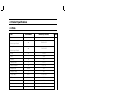
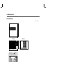
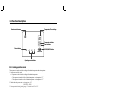
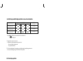
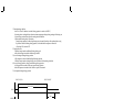
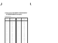
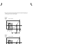
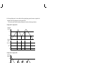
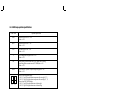
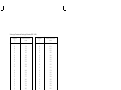
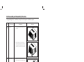
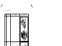
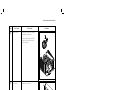
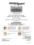
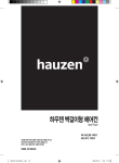
AWH126JE/front
4/7/98 11:44 AM
Page 1
ROOM AIR CONDITIONER
AWH126JE
AWH127JE
SERVICE
AIR CONDITIONER
Manual
CONTENTS
1. Precautions
2. Product Specifications
3. Installation and Operating
Instructions
4. Disassembly and Reassembly
5. Troubleshooting
6. Exploded Views and Parts List
°C
Hour
DEICE
HEAT
COOL
7. Block Diagram
FAN
POWER /
MODE
8. PCB Diagram
9. Wiring Diagram
10. Schematic Diagrams
AWH126JE/front
4/7/98 11:44 AM
Page 2
ELECTRONICS
© Samsung Electronics Co., Ltd. MAR. 1998.
Printed in Korea.
Code No. DB81-10152A
1. Precautions
1. Warning: Prior to repair, disconnect the
power cord from the circuit breaker.
2. Use proper parts: Use only exact
replacement parts. (Also, we recommend
replacing parts rather than repairing them.)
3. Use the proper tools: Use the proper tools
and test equipment, and know how to use
equipment may cause problems laterintermittent contact, for example.
Fig. 1-1 Avoid Dangerous Contact
4. Power Cord: Prior to repair, check the
power cord and replace it if necessary.
5. Avoid using an extension cord, and avoid
tapping into a power cord. This practice
may result in malfunction or fire.
6. After completing repairs and reassembly,
check the insulation resistance, Procedure:
Prior to applying power, measure the
resistance between the power cord and the
ground terminal. The resistance must be
greater than 30 megohms.
Fig. 1-2 No Tapping and No Extension Cords
7. Make sure that the grounds are adequate.
8. Make sure that the installation conditions
are satisfactory. Relocate the unit if
necessary.
9. Keep children away from the unit while it is
being repaired.
10. Be sure to clean the unit and its surrounding
area.
Fig. 1-3 No Kids Nearby!
Fig. 1-4 Clean the Unit
Samsung Electronics
1-1
2. Product Specifications
2-1 Table
Item
Unit of Measure
AWH126/127JE (COOL/HEAT)
Type
-
Window
mm
600 X 394 X 555
mm
715 X 470 X 655
Volt
220 - 240
-
Single
Frequency
Hz
50
Operating Current
A
5.9 / 5.3
Power Consumption
W
1,350 / 1,210
FREON
R-22
g
680
BTU/h
11,500 / 11,500
BTU/h.W
8.5 / 9.5
Net Weight
kg
45
Condenser
Row
2 X 14
Condenser Fan
Type
Propeller Fan
Evaporator
Row
2 X 14
Evaporator Fan
Type
Blower
W
AMAFS100ATEA
Model
48H124JV1E4
-
MRA12030-12008
Dimensions:
(Width X Height X Depth)
Packing Size
(Width X Height X Depth)
Voltage:
Phase
Refrigerant Type
Refrigerant Charge
Cooling Capacity
EER
Fan Motor
Compressor(Rotary)
Overload Protect
Compressor Capacitor
µF/ VAC
30 / 450
Fan Motor Capacitor
µF/ VAC
3.5 / 450
DUAL TYPE
Fan Speed Control
-
Fan speed switch (High & Low)
Thermo Control
-
Thermistor
OFF Timer
hr
24
Samsung Electronics
Remarks
2-1
2-2 Dimensions
2-2-1 Main Unit
595
Unit : mm
Side view
394
Front view
°C
Hour
DEICE
HEAT
COOL
FAN
POWER / MODE
600
2-2-2 Remote Control
Mode selection Buttons
(FAN, HEAT, COOL)
Temperature adjustment buttons
Fan speed adjustment Buttons
(HIGH, LOW)
2-2
Timer setting buttons
ON/OFF Buttons
Air flow swing button
Samsung Electronics
3. Installation and Operating Instructions
3-1 Installation
* When selecting the area for installing the unit, be sure to obtain approval of the customer.
1.
Make sure that you install the unit in an area that
provides good ventilation.
The air conditioner must not be blocked by any
obstacle affecting the air flow near the air inlet and
air outlet.
2.
Make sure that you install the unit in an area which
can endure the weight and vibration of the unit.
3.
Make sure that you install the unit away from heat
or vapor.
4.
Make sure that you install the unit in an area where
the cooled air can be evenly spread in a room.
5.
Make sure that you install the unit in an area away
from TVs, audio units, cordless phones, fluorescent
lighting fixtures and other electrical appliances.
(obtain a clearance of at least one meter)
6.
Make sure that you install the unit in an area which
provides easy drainage for condensed water.
7. Make sure that you install the unit in an area not
exposed to rain or direct sunlight.
(Install a separate sunblind if exposed to direct sunlight.)
8.
Do not install the unit in an area subjected to noise
or vibration amplification which may affect your
neighbor.
(Fix the unit firmly if mounted in a high place.)
Caution:
Do not use the air conditioner in such areas as a greasy area(including machine oil),
saline area(sea side), or sulphuric area(hot spring). When using the air conditioner in these areas,
special maintenance is required. Contact your local dealer or our service center for advice.
Samsung Electronics
3-1
3-2 Function Description
Remote control sensor
Temperature/Timer settings
°C
Hour
Deice indicator
DEICE
HEAT
COOL
Temperature indicator
Timer indicator
POWER/MODE button
FAN
POWER / MODE
Operating mode indicator
3-2-1 Cooling operation mode
The compressor is turned on and off according to the ambient temperature and set temperature.
1. Compressor on and off control
¥ Compressor on and off control according to the ambient temperature.
* The compressor is turned off when "ambient temperature = set temperature -1ûC"
* The compressor is turned on when "ambient temperature = set temperature +1ûC"
2. Default value after power reset → set temperature = 18ûC
FAN SPEED = HIGH
3. Set temperature indicating (setting) range : 1ûC interval from 18ûC to 30ûC.
3-2-2 Heating operation mode
The compressor is turned on and off according to the ambient temperature and set temperature.
1. Compressor on and off control.
¥ Compressor on and off control according to the ambient temperature.
* The compressor is turned off when "ambient temperature = set temperature +1ûC"
* The compressor is turned on when "ambient temperature = set temperature -1ûC"
2. Default value after power reset → set temperature = 24ûC
FAN SPEED = HIGH
3. Set temperature indicating (setting) range : 1ûC interval from 16ûC to 30ûC.
3-2-3 Fan operation mode
1. If "Fan operation mode" signal is received from remocon.
→ the compressor is immediately turned off and only fan motor is operated at set blowing speed.
→ it changes such as "HIGH → LOW → HIGH"( if Fan speed is selected).
2. The initial FAN speed is set to "HIGH".
3. The set temperature can not be indicated and set.
3-2
Samsung Electronics
3-2-4 LED lamp and LED display indication in case of error detection
ERROR OPERATION
COOL
LED LAMP DISPLAY
HEAT
FAN
ROOM THERMISTOR
(OPEN OR SHORT)
INDOOR PIPE THERMISTOR
(OPEN OR SHORT)
OUTDOOR PIPE THERMISTOR
(OPEN OR SHORT)
Lamp
7-SEG
LED DISPLAY
E1 displayed
E5 displayed
E6 displayed
blinking at every second (on for 0.5s and off for 0.5s)
LED lamp off
1. Set operation in case of error occurrence.
¥ Malfunction of each temperature sensor (open, short)
- Error mode display, warning sound.
- The operation status is off.
2. The "outdoor pipe thermistor" error mode carry out checking only during heating operation and
do not carry out checking during "COOLING" and "FAN" operation.
3-2-5 Panel key operation
Key discription
Key name
Power/Mode
Samsung Electronics
Key operational function
1. Operation mode change and POWER OFF(in case of model option heat pump)
* at every ON
- Selected as "OFF –> COOL –> HEAT –> FAN –> OFF". (Default=OFF)
Continuous
operation is not available.
*
Key Type
TACT
3-3
3-2-6 LED lamp operation specifications
LAMP name
COOL
The mode is set to "COOL" –> ON
Others –> OFF
HEAT
The mode is set to "HEAT" –> ON
Others –> OFF
FAN
The mode is set to "FAN" –> ON
Others –> OFF
ûC
The set temperature is displayed or set -> ON
Others –> OFF
HR
During setting of the convenient reserve (OFF TIMER) time -> blinking
After setting of the convenient reserve (OFF TIMER) time -> ON
Others –> OFF
DEICE
(1)
3-4
Operations specifications
(2)
Till the "DEICING" operation is completed during heating opertion -> ON
Others –> OFF
In case of (set) temperature display
-> NO. (1) 7 seg. LED display indicates temperature of the tens digit (ûC, ûF)
-> NO. (2) 7 seg. LED display indicates temperature of the units digit (ûC, ûF)
In case of time (OFF TIMER) display
-> NO. (1) 7 seg. LED display indicates time of the tens digit
-> NO. (2) 7 seg. LED display indicates time of the units digit
Samsung Electronics
3-2-7 Resistor values table of “ROOM THERMISTOR”, “INDOOR PIPE THERMISTOR”
and “OUTDOOR PIPE THERMISTOR” for each temperature
1. Room thermistor (SPEC : 103AT)
Temperature
[˚C]
THERMISTOR RESISTOR
[Kohm]
Temperature
[˚C]
THERMISTOR RESISTOR
[Kohm]
70
69
68
67
66
65
64
63
62
61
60
2.229
2.296
2.365
2.437
2.512
2.589
2.669
2.752
2.838
2.928
3.021
29
28
27
26
25
24
23
22
21
20
8.622
8.944
9.281
9.632
10.000
10.380
10.780
11.200
11.630
12.090
59
58
57
56
55
54
53
52
51
50
3.116
3.216
3.319
3.426
3.537
3.652
3.772
3.897
4.026
4.161
19
18
17
16
15
14
13
12
11
10
12.560
13.060
13.570
14.120
14.680
15.280
15.900
16.550
17.240
17.960
49
48
47
46
45
44
43
42
41
40
4.300
4.444
4.594
4.749
4.912
5.080
5.256
5.439
5.630
5.828
9
8
7
6
5
4
3
2
1
0
18.700
19.480
20.290
21.150
22.050
22.990
23.900
25.030
26.130
27.280
39
38
37
36
35
34
33
32
31
30
6.033
6.246
6.468
6.699
6.941
7.192
7.455
7.729
8.015
8.313
-1
-2
-3
-4
-5
-6
-7
-8
-9
28.470
29.720
31.040
32.430
33.890
35.430
37.050
38.760
40.560
Samsung Electronics
3-5
2. Indoor pipe Thermistor and Outdoor pipe Thermistor (SPEC : 10KD)
3-6
Temperature
[˚C]
THERMISTOR RESISTOR
[Kohm]
Temperature
[˚C]
THERMISTOR RESISTOR
[Kohm]
70
69
68
67
66
65
64
63
62
61
60
1.670
1.729
1.791
1.855
1.922
1.992
2.065
2.141
2.220
2.303
2.390
29
28
27
26
25
24
23
22
21
20
8.354
8.734
9.135
9.556
10.00
10.46
10.94
11.45
11.99
12.55
59
58
57
56
55
54
53
52
51
50
2.480
2.574
2.672
2.775
2.882
2.994
3.111
3.234
3.362
3.496
19
18
17
16
15
14
13
12
11
10
13.15
13.78
14.44
15.14
15.88
16.66
17.48
18.36
19.28
20.25
49
48
47
46
45
44
43
42
41
40
3.635
3.780
3.932
4.091
4.257
4.432
4.614
4.806
5.007
5.217
9
8
7
6
5
4
3
2
1
0
21.28
22.38
23.54
24.76
26.06
27.44
28.90
30.45
32.10
33.85
39
38
37
36
35
34
33
32
31
30
5.438
5.669
5.912
6.167
6.435
6.716
7.012
7.322
7.649
7.993
-1
-2
-3
-4
-5
-6
-7
-8
-9
-10
35.66
37.59
39.64
41.82
44.14
46.60
49.22
52.01
54.98
58.14
Samsung Electronics
3-2-8 About the safety devices
1. High temperature release : If temperature of the indoor pipe thermistor increases over the specified value during heating
operation, following operation is carried out for safety of the equipment.
A condition : temperature of indoor pipe thermistor is below 47ûC
B condition : temperature of indoor pipe thermistor is between 58ûC and 63ûC
C condition : temperature of indoor pipe thermistor is over 63ûC
1) High temperature release operation OFF condition = A condition
-> compressor ON (only in THERMO ON condition)
-> fan motor speed = set fan speed and cool blowing inhibiting operation
2) High temperature release operation ON condition = B condition
-> compressor ON
-> fan motor speed = HIGH operation if it was LOW
= HIGH operation if it was HIGH
3) High temperature release operation ON condition = C condition
-> fan motor speed = set fan speed
-> compressor OFF
2. Low temperature release : If temperature of the indoor pipe thermistor decreases below the specified value during cooling
operation, following operation is carried out for safety of the equipment.
A condition : temperature of indoor pipe thermistor is below -1ûC for more than 6 minutes
B condition : temperature of indoor pipe thermistor is over 5ûC
1) Low temperature release ON condition = A condition
-> compressor OFF
-> fan motor "set fan speed"
2) Low temperature release OFF condition = B condition
-> The compressor is turned on if ON condition is satisfied after comparing the ambient temperature with the set
temperature
-> fan motor "set fan speed"
[Detailed description]
1) If temperature of indoor pipe thermistor is below -1ûC for more than 6 minutes, the fan motor continues to operate at
the set fan speed and the compressor is turned off(Low temperature release operation)
2) If temperature of the indoor pipe thermistor increases over +5ûC during low temperature release operation, normal
operation is recovered
: compressor ON, fan mtor set fan speed -> Low temperature release operation OFF
3) If temperature of indoor pipe thermistor increases over 0ûC during counting 6 minutes below -1ûC, the counter is reset.
Samsung Electronics
3-7
3. Deicing operation : If temperature of the outdoor pipe thermistor decreases below the specified value during heating operation, following operation is carried out for safety of the equipment.
Outdoor pipe
Thermistor
temperature
(A-Condition) : STANDARD
12[ûC]
100min below
-4[ûC]
100min
COUNT
ON
100min 100min
COUNT COUNT
OFF
ON
100min
Outdoor pipe
Thermistor
temperature
12[ûC]
Deicing
operation
ON
5min
Deicing
operation
OFF
Deicing
operation
ON
Deicing
operation
OFF
Deicing
operation
ON
5min
Deicing
operation
OFF
(B-Condition) : STANDARD
30min below
-6[ûC]
30min
30min
30min
COUNT COUNT COUNT
ON
OFF
ON
Outdoor pipe
Thermistor
temperature
12[ûC]
30min
5min
(C-Condition) : STANDARD
10min below
-8[ûC]
10min 10min
10min
COUNT COUNT COUNT
ON
OFF
ON
2min
3-8
Samsung Electronics
1) Deicing detecting condition
¥ If one of A, B and C conditions is satisfied, deicing operation is carried out.(AUBUC)
¥ If counting time is overlapped due to detection reference temperature change during counting of the deicing condition, deicing operation starts when the counting time is finished first.
¥ The maximum counting time is 100 minutes.
- During deicing operation, the left and right swing motor is turned off and stops at the position before swing.
- If operation is turned off during deicing operation, it is finished and the compressor is turned off.
-> Deice lamp ON, fan motor OFF.
2) Display indication.
¥ The deice lamp is turned on additionally during deicing cycle.
¥ Only the deice lamp is turned off when deicing is finished.
3) In case of turning off during deicing operation.
¥ The compressor is turned off after finishing the deicing operation.
¥ The deice lamp is turned on during deicing cycle and is turned off when deicing is finished.
4) In case of changing mode to cooling operation during deicing operation.
¥ Cooling operation is carried out after carrying out deicing operation.
¥ After the compressor is turned off and 1 minutes is passed, it is restarted.
5) Load operation during deicing operation.
ÒDEICEÓ LED OFF
ÒDEICEÓ LED ON
DEICE TIME
CYCLE
1min
COMPRESSOR
OFF
ON
2sec
FAN
MOTOR
ON
OFF
THERMO ON
1sec
COOL BLOWING INHIBITION
4-WAY
VALVE
Samsung Electronics
ON
OFF
SET FAN SPEED
AND COOL
BLOWING
INHIBITION
55sec
3-9
4. Cool blowing inhibiting control : In order to inhibit cool blowing during heating operation, the fan motor is operated when
temperature of the indoor pipe thermistor is above the specified value.
¥ The fan motor speed is controlled according to the temperature of condition of the indoor pipe thermistor.
< Compressor OFF -> Compressor ON >
Indoor pipe
thermistor
32[ûC]
30[ûC]
FAN MOTOR
CONTROL
SET FAN SPEED
LOW FAN
OFF
< Compressor ON -> Compressor OFF >
Indoor pipe
thermistor
32[ûC]
31[ûC]
30[ûC]
FAN MOTOR
CONTROL
LOW FAN
OFF
30sec
1) When the indoor pipe thermistor temperature is increasing
indoor pipe thermistor temperature = below 32ûC --> fan motor OFF
indoor pipe thermistor temperature = over 32ûC --> fan motor speed "set blower speed"
2) When the indoor pipe thermistor temperature is decreasing
indoor pipe thermistor temperature = over 30ûC --> fan motor speed "set blower speed"
indoor pipe thermistor temperature = below 30ûC --> fan motor speed "Low"
3) But if the compressor is operating, the fan motor is not turned off but is operated weakly even if the indoor pipe thermistor temperature decreases.
3-10
Samsung Electronics
< Compressor ON -> Compressor OFF >
indoor pipe thermistor temperature = below 30ûC --> fan motor speed "Low"
indoor pipe thermistor temperature = over 30ûC --> fan motor OFF
30s is passed after compressor is turned off --> fan motor OFF
3-2-9 Compressor delayed operation and 4-way valve delayed operation :
The compressor is turned on after 3 minutes from power resetting or compressor turning off during cooling
or heating operation.
1) The compressor can be turned on after "3 minutes delay" from power resetting or compressor turning off.
2) The 4 way valve is turned off/on after "2 minutes and 55 seconds delay" in the on/off condition.
(during heating operation)
3) The operation is stopped after "2 minutes and 55 seconds delay" in the off condition when the 4 way valve is
turned on.
Samsung Electronics
3-11
4. Disassembly and Reassembly
4-1 Compressor Replacement Flow Chart
Locate cause of defect
Release refrigerant
Disconnect electrical wiring
from compressor
Cut refrigerant lines
from compressor
Plug disconnected lines
Replace compressor
Inspect electrical
wiring for defects,
and terminals for
correct and secure
connections
Solder discharge line
Solder suction line
Use nitrogen gas
Perform soldering function
Problem?
Fill system with nitrogen gas
Y
N
Check for leakage
Y
Leakage?
Corrective action
Check refrigerant oil level
N
Release nitrogen gas?
Low oil level?
Y
N
Evacuate system
Add oil as necessary
Recharge system
Recharge system
Samsung Electronics
4-1
4-2 Checking the oil
Fill the transparent container with 10cc of oil, and then conduct the test.
4-2-1 Oil quality
Refrigerant Cycle
Oil Condition
Color
Odor
Remarks
Normal
Light Yellow
No Odor
Return with the system
Over-heated
Brown
-
Oil Change
Compressor damage
Dark brown
Pungent oil
Oil Change
4-2-2 Replacing and refilling the refrigerant oil
1. Replacing the compressor - Do not fill the system with oil as the compressor is already charged.
2. Replacing the condenser - Refill 50cc.
3. Replacing the evaporator - Refill 50cc.
4. Replacing the refrigerant - Refill 30cc.
5. The high pressure side is filled up with oil after the vacuum is completed.
6. When the refrigerant leaks, it is generally not necessary to refill the oil if the leakage is not severe.
4-2
Samsung Electronics
4-4 Disassembly and Reassembly Procedure
Stop operating the air conditioner, and pull out the power cord before repair.
No.
➀
Part name
Ass'y Grill
Procedures
Remarks
1. Pull the grille air inlet and remove the screw
on the grille
DEICE
°C
HEAT
COOL
Hour
FAN
POWER
/ MODE
2. Hold the lower part of the grill with two
hands while pressing down on both sides of
the lower part of the cabinet, pull it forward
by about 30, and then lift it up for removal.
DEICE
°C
HEAT
Hour
COOL
FAN
POWE
R/
➁
Ass'y Cabinet
MOD
E
1. Remove the screws on both sides of the
cabinet to disconnect the cabinet and frame.
2. Pull the handle on the front side of the
bottom, and remove the unit from the
cabinet.
DEICE
°C
HEAT
COOL
Hour
FAN
POWER
/ MODE
➂
Ass'y Control
1. Remove 6 screws,
and earth wire screw.
2. Remove four lead wire assemblies and the
deice sensor from the condenser.
3. Remove the blade V and arm blade.
4. Take out the control box forward.
DEICE
°C
HEAT
COOL
Hour
FAN
POW
ER
Samsung Electronics
/ MOD
E
4-3
Disassembly and Reassembly
No.
Part name
Procedures
➃
Frame Up
1. Remove 10 screws on the Frame Up.
➄
Case Cond &
Propeller Fan
1. Remove two screws on the bottom side,
and 5 screws on the case cond.
Remarks
2. Remove the nut flange, and remove the
propellr fan
4-4
Samsung Electronics
Disassembly and Reassembly
No.
➅
Part name
Blower & Motor
Procedures
Remarks
1. Remove two screws on the clip motor,
and remove the clip motor.
2. Move the motor & blower toward the
evap, and lift up the motor & blower
from the frame low.
➆
Cond Casing
Samsung Electronics
1. Remove the cond casing
4-5
5. Troubleshooting
Check the basic checkpoints first to determine whether it is machine trouble or a problem in the
operation method. When it is not related to the basic checkpoints, perform checking in accordance
with the procedures of troubleshooting by symptom.
5-1 Basic Checkpoints for Troubleshooting
1) Is the voltage of the power source appropriate ?
(1)It should be within the range of AC 198V ~ 264V.
(2)The air conditioner may not operate properly when the voltage is out of this range.
2) Is the connection with the fan motor, compressor wire, and starting condenser
appropriately made ?
3) The symptoms listed in the table below are not indicative of machine trouble.
Symptom
Cause and check
No operation
• Check whether there is power failure or the power plug is pulled out.
• Check whether the unit is stopped as a result of completion
of the sleep time.
• Pull out the power plug for ten seconds, and then insert it again.
Air flows, but
no cooling
no Heating
• Check whether the Air filter is clogged with dust or is dirty.
• Check whether the desired temperature is too high. Set the desired
temperature to a lower level than the current temperature.(Cooling)
• Check whether it is in "FAN" mode.
• Check whether the desired temperature is too low. Set the desired
temperature to a higher level than the current temperature.(Heating)
• Check whether the unit is deicing.
The remocon does
not operate
• Check whether battery is completely depleted.
• Check whether the battery is properly inserted.
• Check whether the receiving window of the remocon for the assembly
panel PCB is blinded.
• Check whether the remocon is affected by jamming due to a neon sign.
No temperature
setting
• Check whether the unit is in "FAN" mode.
(In "FAN" mode, only the current temperature is displayed, and the
desired temperature is not set.)
¥ Checking and Display of Fault Area
ERROR OPERATION
COOL
LED LAMP
HEAT
ROOM THERMISTOR
(OPEN OR SHORT)
INDOOR PIPE THERMISTOR
(OPEN OR SHORT)
OUTDOOR PIPE THERMISTOR
(OPEN OR SHORT)
* Lamp
FAN
7-SEG
LED DISPLAY
E1 displayed
E5 displayed
E6 displayed
--- blinking at every second (on for 0.5s and off for 0.5s)
--- LED Lamp off
Samsung Electronics
5-1
5-2 Troubleshooting by Symptom
5-2-1 No power
1) Check points
(1) Is the voltage of the power source normal ? (AC 198V ~ AC 264V)
(2) Is the electric wire in good contact ?(CN 71, RY 71)
(3) Is the output voltage of the IC01(KA 7812) normal ?(DC 11.5V ~ DC 12.5V)
(4) Is the output voltage of the IC02(KA 7805) normal ?(DC 4.5V ~ DC 5.5V)
(5) Is the connection of the assembly main PCB, and assembly panel PCB in good contact?(CN11, CN12)
Turn off the power, and then turn it on again five
seconds later.
Dose the buzzer sound, when the power ON?
Y
Normal operation.
N
Check whether the "COOL" LED lamp is on, and the
operation starts when pressing the ON/OFF button of
the remocon.
Y
Normal operation.
N
Is the F01(3.15A) fuse blown?
Y
Replace the fuse.
N
Is the primary voltage of the trans normal?
(AC 198V ~ AC 264V)
N
Check the power cord and electric wire.
Y
Is the secondary voltage of the trans normal?
(AC 13V ~ AC 17V)
N
Check and replace the trans.
Y
Is the rectifying diode(D101~D106) normal?
N
• Check the D101 ~ D106 for cold soldering.
• Replace the diode
Y
Is the voltage of DC 17V ~ DC 23V applied at both
ends of the C102 electrolytic condenser?
Is the voltage of DC 12V applied at both ends of
the C104 electrolytic condenser?
Is the voltage of DC 5V applied at both ends of
the C105 electrolytic condenser?
Y
Are the IC01(KA7812) and IC02(KA7805) normal?
Y
N
N
• Check both ends of the C102 for short
and cold soldering.
• Check the +12V for a short.
• Check the +5V for a short.
• Check and replace the C102, C104,
and C105.
• Check the IC01, and IC02 for cold
soldering and a short.
• Replace the IC01, and IC02.
Replace the assembly main PCB.
5-2
Samsung Electronics
5-2-2 When the assembly panel PCB is not operated
1) Check points
(1) Is the voltage of the power source normal ?(AC 198V ~ AC 264V)
(2) Is the electric wire in good contact ?(CN71, RY71)
(3) Is the connection of the assembly main PCB, and assembly panel PCB in good contact?
(CN11, CN12)
(4) Is the voltage of +12V normal ?(CN 12 No 1 pin and No 12 pin : +12V±0.5V)
(5) Is the voltage of +5V normal ?(CN12 No 2 pin and No 12 pin : +5V±0.5V)
Turn off the power, and then turn it on again
five seconds later.
N
Normal operation
When the LED lamp is
not operated.
Y
Check the micom
(IC02) for a short,
and replace it.
N
Is the voltage of the micom
(IC02) No.47~50 port a square
wave?
Y
Check the micom
(IC02) for a short,
and replace it.
N
Is the voltage of the micom
(IC02) No.56,58~63 port a
square wave?
Y
Check the IC03
for a short, and
replace it.
N
Is the voltage of the
IC03 No. 15~18 a
square wave?
When the TACT switch is
not operated.
N
Normal operation
Y
Is the voltage of the
micom (IC02) No.50port
a square wave?
N
Check the micom
(IC02) for a short,
and replace it.
N
Check the micom
(IC02) for a short,
and replace it.
Y
Is the voltage of the
micom(IC02) No.44port a
square wave?
Y
Replace the assembly
panel PCB.
Y
Check the IC04
for a short, and
replace it.
N
Is the voltage of the
IC04 No. 10~16 a
square value?
Y
Replace the assembly panel PCB
Samsung Electronics
5-3
5-2-3 When the remocon is not operated
1) Check points
(1) Is the voltage of the power source normal ? (AC 198 ~ AC 264V)
(2) Is the electric wire in good contact ? (CN71, RY71)
(3) Is the assembly main PCB in good contact with the assembly panel PCB?(CN11, CN12)
(4) Is the voltage of +12V and +5V of the assembly panel PCB normal?
(CN12 No 1 pin and No 12 pin : +12V, No 2 pin and No 12 pin : +5V)
(5) Is battery voltage of the remocon above DC 2.7V?
Turn off the power, and then turn it on
again five seconds later.
Y
Go to the clause "No power".
Dose the Buzzer Sound, when the power ON?
Y
Check whether the "COOL" LED lamp is on
and th operation starts when pressing the
on/off button of the remocon.
Y
The remocon is normally operated.
N
Is the battery voltage of the remocon above
DC 2.7V?
N
Replace the battery.
Y
N
• Check the X-TAL for cold soldering and a
short.
• Replace relevant components.
N
• Check the micom(ICT1) QT1, and QT2 for
cold soldering and a short.
• Replace relevant components.
Does the X-TAL(RJ455JB) oscillate normally?
Y
Is the collector voltage of the remocon QT1, QT2(C2412)
a square wave?
Y
Is the input voltage of the micom(IC02) No. 26
pin of the assembly main PCB a aquare wave?
N
• Check the R202 and C202 components.
• Check the micom(IC02).
Y
Replace the assembly panel PCB.
5-4
Samsung Electronics
5-2-4 When the compressor is not operated
1) Check points
(1) Is the voltage of the power source normal ? (AC 198V ~ AC 264V)
(2) Is the desired temperature lower than the indoor temperature in the ÒCOOLÓ mode?
(Compressor stopped)
(3) Is the desired temperature higher than the indoor temperature in the ÒHEATÓ mode?
(Compressor stopped)
(4) Is the starting condenser in good contact?
(5) Is the electric wire in good contact ? (CN71, RY71)
(6) Is the output voltage of the IC01(KA7812) and IC02(KA7805) normal ?
Turn off the power, and then turn it on again five
seconds later.
N
Go to the clause "No power".
Dose the Buzzer sound, when the pwer ON?
Y
Check whether the "COOL" LED lamp is on and the
operation starts when pressing the on/off button
of the remocon?
N
• Go to the clause "when he remocon
does not operate".
Y
Check whether the compressor is activated in three
minutes after turning on the power with the "COOL" or
"HEAT" LED lamp being switched on when selecting the
cool mode of the remocon.
Y
Normal operation.
N
Is the IC03(MAIN PCB) output normal?
When the compressor is ON, IC03(MAIN PCB)
No. 14 pin –> Low.
N
• Check the IC03(MAIN PCB) for short and
cold soldering.
• Replace the IC03(MAIN PCB).
N
• Check the relay coil resistance.
(resistance : About 150Ω±20Ω)
• Replace the relay.
Y
Does the relay(RY71) operate normally?
When the compressor is ON, the RY71 should operat.
Y
Is the compressor normal?
Y
N
• Check the operation of the O.L.P,
and replace it if necessary.
• Check the compressor
resistance.(0Ω : short, ∞Ω : open)
Replace the compressor.
Samsung Electronics
5-5
5-2-5 When the air swing motor is not operated
1) Check points
(1) Is the voltage of the power source normal ?(AC198V ~ AC264V)
(2) Is the electric wire in good contact ?(CN71, RY71)
(3) Is the swing motor conector in good contact?(CN71)
(4) Is the terminal connector to the swing motor in good contact?
(5) Is the output voltage of the IC01(KA7812) and IC02(KA7805) normal?
Turn off the power, and then turn it on again five
seconds later.
N
Go to the clause "No power".
Dose the buzzer sound, when the power ON?
Y
Check whether the “COOL” LED lamp is on, and the
operation starts when pressing the ON/OFF button of the
remocon?
N
Go to the clause of “when the remocon
dose not operated”
Y
Does the air-swing motor operate when
pressing the air-swing button of the remote control?
Y
Normal operation.
N
Is the IC03(MAIN PCB) output normal?
When the air-swing motor is on, IC03(MAIN PCB)
No. 12 pin ➝ Low
N
• Check the IC03(MAIN PCB) for a short
and cold soldering.
• Replace the IC03(MAIN PCB).
N
• Check the relay coil resistance.
(Normal: About 400Ω)
• Replace the relay.
N
• Check the air-swing motor resistance.
(0Ω : short, ∞Ω : open)
Y
Does the relay(RY 75) operate normally?
When the air-swing motor is operated, the
RY74 should be operated.
Y
Is the air-swing motor normal?
Y
Replace the air-swing motor.
5-6
Samsung Electronics
5-2-6 When the fan motor does not operated
1) Check points
(1) Is the voltage of the power source normal ?(AC198V ~ AC264V)
(2) Is the electric wire in good contact ?(CN71, RY71)
(3) Is the starting condenser in good contact?
(4) Is the fan motor connector in good contact?(CN73)
(5) Is the output voltage of the IC01(KA7812) and IC02(KA7805) normal ?
Turn off the power, and then turn it on again five
seconds later.
N
Go to the clause "No power".
Dose the buzzer sound, when the power ON?
Y
Check whether the "COOL" LED lamp is on and the
operation starts when pressing the on/off button
of the remocon.
N
• Go to the clause of "when the remocon
does not operated".
N
• Check the IC03(MAIN PCB) for a short
and cold soldering.
• Replace the IC03(MAIN PCB).
N
• Check the relay coil resistance.
(Normal: About 400Ω)
• Replace the relay.
N
• Check the fan motor resistance.
(0Ω : short, ∞Ω : open)
Y
Is the IC03(MAIN PCB) output normal?
When the fan motor is High, IC03(MAIN PCB)
No. 14 pin –> LOW.
When the fan motor is Low, IC03(MAIN PCB)
No. 15 pin –> LOW.
Y
Does the relay(RY 72, 73) operate normally?
When the fan motor is High, RY72 should operate.
When the fan motor is Low, RY73 should operate.
Y
Is the fan motor normal?
Y
Replace the fan motor.
Samsung Electronics
5-7
5-2-7 When the 4-way valve is not operated
1) Check points
(1) Is the voltage of the power source normal ?(AC198V ~ AC264V)
(2) Is the electric wire in good contact ?(CN72)
(3) Is the 4-way valve connector in good contact?(CN72)
(4) Is the output voltage of the IC01(KA7812) and IC02(KA7805) normal?
(5) Is the unit heating cycle?
Turn off the power, and then turn it on again five
seconds later.
N
Go to the clause "No power".
Dose the buzzer sound, when the power ON?
Y
Does the 4-way valve operate when
pressing the HEAT button of the remote control?
Y
• Normal operation
(Operating the "Heat", relay about 3 minutes until the "4-way valve" operates.)
N
• Check the IC03(MAIN PCB) for a short
and cold soldering.
• Replace the IC03(MAIN PCB).
N
• Check the relay coil resistance.
(Normal: About 400Ω)
• Replace the relay.
N
• Check the fan motor resistance.
(0Ω : short, ∞Ω : open)
N
Is the IC03(MAIN PCB) output normal?
When the air-swing motor is on, IC03(MAIN PCB)
No. 13 pin ➝ Low
Y
Does the relay(RY 74) operate normally?
When the air-swing motor is operated, the
RY74 should be operated.
Y
Is the 4-way valve coil normal?
Y
Replace the 4-way valve coil.
5-8
Samsung Electronics
1
27
6-1
2
28
26
13
3
10
12
4
8
9
11
5
15
3
6
2
5
7
4
1
14
6
7
12
8
14
9
16
15
18
13
19
17
10
20
11
24
22
21
25
23
6. Exploded View and Parts List
6-1 Main unit
Samsung Electronics
■ Part List
Q'TY
No.
Code No.
Description
Remarks
Specification
AWH126JE
AWH127JE
1
DB64-10145A
GRILL AIR INLET
HIPS
1
1
2
DB63-30142A
GUARD AIR FILTER
HIPS
1
1
3
DB64-70080A
PANEL FRONT
HIPS
1
1
4
DB66-30169A
BLADE-H
PP
1
1
5
DB96-40176A
ASSY EVAP
AWH126JE
1
1
6
DB90-50133A
ASSY FRAME LOW
AWH120JE
1
1
7
DB67-50073A
BLOWER
ABS+G/F
1
1
8
DB65-10101A
CLIP MOTOR
SECC-P
1
1
9
DB31-10145A
MOTOR
AMAFS110ZTEA
1
1
10
DB67-50072A
FAN PROPELLER
ABS+G/F
1
1
11
DB61-10152A
CASE COND
PP
1
1
12
DB90-50142A
ASSY FRANE UP
AWH120JE
1
1
13
DB96-30283A
ASSY COND
AWH126JE
1
1
14
DB63--10355A
CAP DRAIN
CR
1
1
15
DB90-20198A
ASSY BASE
AWH121JE, 48F
1
1
16
DB27-10030B
ASS’Y SOLENOID COIL
AWH090ZE
1
1
17
DB62-31722A
TUBE CAPILLARY ASS’Y
ID 1,7, L1300
1
1
18
DB96-10591A
ASS’Y TUBE 4-WAY V/V
AWH120JE
1
1
19
DB95-10062X
ASS’Y COMP
48H124JV1E4
1
1
20
DB72-50585A
CLOTHE SOUND
T35
1
1
21
DB60-30028A
NUT WASHER
M8, ZPC
3
3
22
DB73-10004A
GROMMET-ISOLATOR
EPDM
3
3
23
DB63-10165A
COVER TERMINAL
NORYL, BLK
1
1
24
DB60-30018A
NUT-FLANGE
M5, SM20C
1
1
25
DB47-20001Z
OLP-POLYESTER
MRA12030-12008
1
1
26
DB90-10586A
ASS’Y CABINET
AWH120JE
1
1
27
DB63-30145A
GUARD-C/FILTER
PP
-
1
28
DB98-11178D
ASS’Y CONTROL
AWH126JE
1
1
Samsung Electronics
6-2
6-2 Ass’y Control
2
4
3
1
11
8
14
10
7
9
5
15
13
6-3
12
6
Samsung Electronics
■ Part List : ASS’Y CONTROL
Q'TY
No.
Code No.
Description
Remarks
Specification
AWH126JE
AWH127JE
0
DB98-11178D
ASS’Y CONTROL
AWH126JE
1
1
1
DB61-10153A
CASE CONTROL
SECC-P, TO.8
1
1
2
DB66-30170A
BLADE-V
PP
1
1
3
DB66-70024A
LEVER DAMPER
HIPS
1
1
4
DB66-70022A
ARM-BLADE
ABS
1
1
5
2501-001124
C-OIL
3.5/30µF, 450VAC
1
1
6
DB65-10100A
CLIP-CAPACITOR
SEEC-P, TO.8
1
1
7
DB95-20065F
SWING MOTOR
M2LJ49ZU32
1
1
8
DB93-10499A
ASS’Y MAIN PCB
AWH126JE
1
1
9
DB93-10500A
ASS’Y PANEL PCB
AWH126JE
1
1
10
DB39-20188B
C/W DISPLAY
AWH126JE
1
1
11
DB32-10051A
THERMISTOR
AWH126JE
1
1
12
DB64-70083A
PANEL-CONTROL E
HIPS
1
1
13
DB64-40177A
INLAY-CONTROL R
AWH126JE
1
1
14
DB32-10045A
THERMISTOR-COND
AWH126JE
1
1
15
DB39-10086A
POWER CORD ASSY
UCP-2
1
1
Samsung Electronics
6-4
6-3 ASS’Y REMOCON(DB93-30056C)
2
5
3
1
7
6
4
■ Part List
Q'TY
No.
Code No.
Description
Remarks
Specification
AWH126JE
AWH127JE
DB93-30056C
ASS’Y REMOCON
ARH-200
1
1
1
DB61-10150A
CASE REMOCON(UPP)
ABS
1
1
2
DB61-10145A
CASE REMOCON(LW)
ABS
1
1
3
DB73-20112C
RUBBER(BT)
NBR
1
1
4
DB93-10516B
ASS’Y-REMOCON PCB
AWH126JE
1
1
5
DB74-10084A
FILTER-REMOCON
PC
1
1
6
DB63-10477A
COVER BATTERY
ABS
1
1
7
DB64-40108C
INLAY-REMOCON
PC
1
1
6-5
Samsung Electronics
7. Block Diagram
7-1 Refrigerating Cycle Block Diagram
Capillay tube
Heat
exchanger
(Condenser)
fan
Heat
exchanger
(Evaporator)
Propeller fan
Check V/V
T1
T2
4-way valve
Compressor
Cooling
Heating
7-2 Basic Structure
7-2-1 Micom Control Diagram
MICOM
LED CONTROL
Indoor Temperature Sensor
outdoor Temperature Sensor
Room Temperature Sensor
A/D converter
Deice Temperature Option
Deice Time Option
• Mode(COOL, HEAT, FAN)
• Temperature Display
• Deice
• Temp
• HR
Remocon Single Receiving
Receiving Unit of Remocon
Remote Cotrol
FAN SPEED(HIGH,LOW)
TEMP. SETTING(▼▲)
• Air swing motor control
• Compressor control
• 4-way valve control
• Buzzer control
• Temperature control
TIMER SETTING(▼▲)
COOL
HEAT
FAN
ON/OFF
Compressor
Fan motor
4-way valve
Air swing motor
Power circuit (DC 5V)
Reset Circuit
Oscillation Circuit
Power circuit (DC 12V)
Down Trans (AC13V ~ AC17V)
AIR SWING
Power input (AC198V ~ AC264V)
7-1
Samsung Electronics
7-2-2 Micom Pin Assignment
( MB89635)
MODEL OPTION
TEMPERATURE OPTION
GND
RS-232C
RS-232C
GND
GND
GND
BUZZER
GND
ROOM THERMISTOR
INDOOR PIPE THERMISTOR
OUTDOOR PIPE THERMISTOR
GND
GND
GND
DEICE TEMPERATURE OPTION
DEICE TIME OPTION
VCC
VCC
GND
GND
GND
GND
GND
REMOTE CONTROL SINGLE INPUT
RESET IC OUTPUT
GND
GND
10MHz RESONATOR
10MHz RESONATOR
GND
1
2
3
4
5
6
7
8
9
10
11
12
13
14
15
16
17
18
19
20
21
22
23
24
25
26
27
28
29
30
31
32
P31
P30
P43
P42/UI2
P41/UO2
P40
P53
P52
P51/BZ
P50
P60/AN0
P61/AN1
P62/AN2
P63/AN3
P64/AN4
P65/AN5
P66/AN6
P67/AN7
AVcc
AVr
AVss
P74
P73/INT3
P72/INT2
P71/INT1
P70/INT0
RST
MOD0
MOD1
X0
X1
Vss
<MODEL OPTION>
<DEICE TIME OPTION>
AN6(#7)
~1V
~1.9V
2V~
2.9V
LED DISPLAY CONTROL
VCC
GND
GND
GND
GND
GND
GND
GND
TEST(Time shortened)
POWER/MODE KEY
GND
GND
GND
COMPRESSOR
HIGH(FAN MOTOR)
LOW(FAN MOTOR)
4-WAY
SWING MOTOR
GND
GND
NC(OUTPUT PORT)
3V~
3.9V
P30(#2)
HIGH
LOW
OPTION
°C
°F
NOTE
TEMP DISPLAY UNIT
TEMP DISPLAY UNIT
<DEICE TEMPERATURE OPTION>
4V~
4.9V
standard standard
standard standard
standard
-2min
-1min
+1min +2min
Samsung Electronics
64
63
62
61
60
59
58
57
56
55
54
53
52
51
50
49
48
47
46
45
44
43
42
41
40
39
38
37
36
35
34
33
<TEMPERATURE DISPLAY OPTION>
P31(#1) OPTION
NOTE
HIGH COOLING AW126JE(COOLING ONLY)
LOW HEAT PUMP AWH126JE(HEAT PUMP)
GND
0.9V
Vcc
P32
P33
P34
P35
P36
P37
Vss
P00
P01
P02
P03
P04
P05
P06
P07
P10
P11
P12
P13
P14
P15
P16
P17
P20
P21
P22
P23
P24
P25
P26
P27
GND
0.9V
AN7(#18)
~1V
~1.9V
2V~
2.9V
3V~
3.9V
4V~
4.9V
standard standard
standard standard
standard
-1°C
+1°C
+2°C
-2°C
7-2
8. PCB Diagram
8-1 Main PCB ( ASS'Y CODE NO : DB93-10499A )
8-1
Samsung Electronics
■ Part List
No.
Description
Code No.
Specification
Q'TY
1
2
3
4
5
ASSY MAIN PCB
FUSE
DIODE RECT
IC VOLT REGU
IC VOLT REGU
DB93-10499A
DE32-10037A
0402-000137
DE13-20008A
DE13-20016A
AWH126JE
FST 250V 3.15A
1N4007
KA7812 TO-220AB
KA7805 TO-220AB
1
1
6
1
1
F01
D101~D106
IC01
IC02
6
7
8
9
10
SCREW TAPPING
HEAT SINK
C-AL
C-AL
C-AL
DE60-10100A
DE62-30039A
2401-000710
2401-000180
2401-001397
M3*6 FEFZY
AL H25
2200uF/25V
1000uF/35V
470uF/25V
1
1
1
1
1
C104
C102
C105
11
12
13
14
15
FUSE HOLDER
SPARK KILLER
RELAY
RELAY POWER
BUZZER
DE47-40024A
DE47-30019A
3501-000399
DB47-90081A
DE30-20016A
FH-51H 7.5A
ESQ1201
JQ1A-12V
JM1aN DC12V
CBE 2220BA STICK
1
1
4
1
1
F01
SK01
RY72~RY75
RY71
BZ601
16
17
18
19
20
VARISTOR
CONNECTOR WAFER
CONNECTOR WAFER
CONNECTOR WAFER
CONNECTOR WAFER
1405-000147
3711-000654
3711-003405
3711-000203
3711-003407
14D-471K
SMW250-12
YW396-03AV BLK
YW396-03AV WHT
YW396-03AV RED
1
1
1
1
1
VA71
CN11
CN72
CN71
CN73
21
22
23
24
25
WIRE-SO, COPPER
PCB MAIN
TRANS L.V
CONNECTOR HEADER
CONNECTOR WAFER
DE39-60001A
DE41-10428A
DE26-20114A
3711-000940
PI 0.6 SN 52MM
AWH126JE
230V 17V
JSW250-02 RED
SMW250-04 WHT
4
1
1
1
1
J01~J04
PCB
TN01
CN41
CN42
26
27
28
29
30
IC-DRIVE
R-METAL FILM
R-CARBON
R-CARBON
R-CARBON
DE27-20017A
2004-000218
2001-001172
2001-000003
2001-000290
KID65003AP
RD 1/8 TP 103-F
RD 1/2T 621-J
RD 1/8T 331-J
RD 1/8T 103-J
1
2
1
4
1
IC03
R402, R403
R601
R203, R301, R302, R303
R101
31
32
C-CERAMIC
R-METAL FILM
2202-000780
2004-001137
100nF/50V
RD 1/8 TP 682-F
2
1
C101, C103
R401
Samsung Electronics
Remarks
8-2
8-2 Display PCB (ASS'Y CODE NO : DB93-10500A)
■ Part List
No.
Description
Code No.
Specification
1
2
3
4
5
ASS’Y PANEL PCB
LED LAMP
LED LAMP
MODULE REMOCON
CONNECTOR WAFER
DB93-10500A
DB07-10021A
DB07-10019A
DB32-50023A
3711-000643
AWH126JE
LTL-4233(GRN)
LTL-4213(RED)
TSOP1238TBI
SMAW250-12
1
4
2
1
1
LE03, LE05, LE06, LE07
LE02, LE04
RM41
CN12
6
7
8
9
10
HOLDER-SEVEN
IC-SOURCE DRIVE
WIRE-SO, COPPER
SW TACT V
PCB PANEL
DB61-90080A
1003-000217
DE39-60001A
3404-000280
DE41-10429A
ABS
UDN2981A
PI 06 SN 52MM
KPT1115A
AWH126JE
1
1
26
1
1
IC03
J01~J25, SW01
SW901
PCB
11
12
13
14
15
R-CARBON
LED-DISPLAY
IC-DRIVE
C-CERAMIC
R-CARBON
2001-000776
DE07-20028A
DE13-20017A
2201-000796
2001-000429
RD 1/2 TP 471
SSD-A3202GMT-S GRN
KID65003AP
1nF/50V
RD 1/8 TP 102-J
7
1
1
1
2
R901~R907
LE01
IC04
C203
R108, R201
16
17
18
19
20
R-CARBON
C-CERAMIC
C-CERAMIC
CERAMIC RESONATOR
R-CARBON
2001-000003
2202-000780
2202-000121
2802-000103
2001-000290
RD 1/8 TP 331-J
100nF/50V
101K 0A/50V
10Mhz
RD 1/8 TP 103J
2
7
1
1
8
R202, R203
C101~C106, C201
C202
X501
R101~R106, 109, r204
21
22
23
IC-MCU
IC
R-CARBON
DE13-20009A
2001-000241
MB89635KA7533 DIP
RD1/8TP152-J
1
1
1
IC02
IC01
R107
8-3
Remarks
Q'TY
Samsung Electronics
8-3 ASS’Y PCB-REMOCON (ASS’Y CODE NO : DB93-10516B)
(BOTTOM)
(TOP)
■ Part List
No.
Description
Code No.
Specification
Q'TY
1
PCB
A3083-043-00
49 X 113.52 X 1.6
1
2
IC
AC09-10453K
KS5180-19
1
3
RESONATOR
A1283-0069
RJ455JB
1
4
TR-CHIP
A4050-0168
2SC2412
2
5
IR-LED
A4150-0168
SI5012-H
2
6
C-ELEC
61079-421-120
50V 4.7 uF
1
7
C-CERAMIC CHIP
A4150-131-101
CL21C101J BNCS
1
8
C-CERAMIC CHIP
A4150-131-101
CL21C101J BNCS
1
9
R-MG CHIP
61079-917-010
RMC 1/10 1.0-J
1
10
R-MG CHIP
61079-917-564
RMC 1/10 560K-J
1
11
R-MG CHIP
61079-917-331
RMC 1/10 330-J
1
12
CHIP DIODE
32167-662-012
DAP202K
1
Samsung Electronics
Remarks
8-4
9. Wiring Diagram
9-1 AWH126JE / AWH127JE
DIAGRAM-ELECTRIC CAPACITOR : 3.5/30 µF 450VAC
(DB68-20702A)
POWER SOURCE : 220V-240V~/50Hz
9-1
Samsung Electronics
10. Schematic Diagrams
10-1 Indoor Unit
Samsung Electronics
10-1
10-2 Remote Control
Samsung Electronics
10-2