1
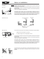
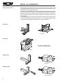
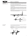
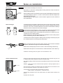
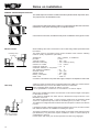
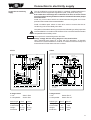
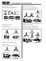
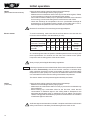
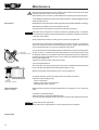
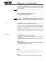
Installation and
Maintenance
Instructions
KG / KGW Standard air-conditioning units
Wolf GmbH · 84048 Mainburg · Postfach 1380 · Telefon 08751/74-0 · Telefax 08751/741600
Art.-Nr. 30 40 530
10/00 TV GB
1
Contents
Contents ...................................................................................... Page
Warnings / Notes on safety .................................................................. 3
Standards ............................................................................................ 4
Delivery to site / Transportation ............................................................ 5
Notes on installation........................................................................ 6-12
Connection to electricity supply .................................................... 13-14
Initial operation .............................................................................. 15-17
Maintenance ................................................................................. 18-19
Protection against frost ...................................................................... 19
2
Warnings /
Notes on safety
General
These Installation and Maintenance Instructions apply only to WOLF KG and KGW
Standard air-conditioning units.
The persons charged with the installation, initial operation or maintenance of the
equipment must read these instructions before commencing work.
Compliance with these instructions is mandatory.
Non-compliance with the installation or maintenance instructions voids the WOLF
guarantee.
Warnings
The following symbols and warnings are used in these Installation and Maintenance Instructions:
Non-compliance with notes marked in this way can endanger persons.
Caution Non-compliance with notes marked in this way can result in damage to the airconditioning unit or its components.
In addition to the warnings in these Installation and Maintenance Instructions,
adhesive warning labels are affixed to the air-conditioning unit.
Compliance with these warnings, too, is mandatory.
Notes on safety
- Installation, initial operation, maintenance and operation of the air-conditioning
unit must be entrusted to adequately qualified and trained persons.
- All work on electrical systems must be performed by a trained and qualified
electrician.
- Work on electrical systems is subject to VDE regulations and the regulations
of the local power utility.
- Operate the air-conditioning unit only within the nominal range specified in the
WOLF technical documentation.
- Use as designated by the manufacturer is use solely for the purposes of
ventilation.
Atmospheric air is the only permitted medium.
This air must be free of noxious, flammable, explosive, aggressive, corrosionpromoting or otherwise hazardous constituents.
(Air-conditioning units rated "Ex-Schutz" in compliance with VDMA Guideline
24169/1 (suitable for use in hazardous environments) can be used to handle air
mixed with explosive gases, vapours or mists in accordance with the equipment
ratings for hazardous-environment classes 1 and 2).
- Do not remove or bypass safety devices or monitoring devices, or render such
devices ineffective in any other way.
- Do not operate the air-conditioning unit unless it is in perfect working order.
Faults and damage detrimental to or potentially detrimental to safety must be
repaired immediately by a specialist.
- Use only genuine WOLF components as replacements for damaged or defective
parts and components.
3
Standards
Standards
The standards and regulations applicable to the KG 15-250 Standard series and
the KG/KGW 630-1000 series air-conditioning units are as follows:
- EC Directive 89/392/EC with Addendum 93/44/EC
(9th Ordinance, Equipment Safety Law)
- E Directive 89/336/EC with Addendum 92/31/EC
(Law concerning Electromagnetic Compatibility of Devices)
- EC Directive 73/23/EC (Low Voltage Directive)
(1st Ordinance, Equipment Safety Law)
- DIN 31001/1
Safety design of technical products
- DIN EN 292
Safety of machinery, basic concepts
- DIN EN 294
Safety of machinery, safety distances
- DIN EN 349
Safety of machinery, minimum gaps
- DIN ISO 1940/1
Mechanical vibration, balance quality requirements
- VDMA 24167
Fans; safety requirements
- VDE 0100
Erection of power installations with rated voltages below
1000V
- VDE 0105
Operation of power installations
- VDE 0700/Part 500 Safety of household and similar electrical appliances
- VDE 0701/Part 1
Repair, modification and inspection of electrical
appliances
- VBG 5
Powered equipment
- VBG 7w
Fans
Plus the following, only for special air-conditioning units for use in hazardous
environments:
- VDMA 24169/1
Guideline for fans for handling atmosphere containing
flammable gases, vapours or mist.
Plus the following, only for weatherproofed air-conditioning units:
- VDMA 24175
4
Roof-mounted air-handling units
Delivery to site / Transportation
Delivery to site
Transport
KG 15-250 and KG/KWG 630-1000 series air conditioners are delivered to site in
transportable units.
Check all incoming goods for signs of damage in transit.
Make a note of all damage or suspected damage on the waybill and have this
damage report countersigned by the delivering freight forwarder.
Immediately report the situation to WOLF.
Caution
The equipment must always be transported right way up, in other words in the
position corresponding to the as-installed position.
Exception: KGXD 160/250 upright is transported on its side (turned through 90°).
Use straps of adequate load-bearing strength to carry the suspended load.
If you use a fork-lift or rollers to move the equipment, always make sure that the
forks or rollers are beneath the frame sections, not beneath the floor panels.
If you suspend the load by means of eyebolts (on request), make sure that the
length of each rope run is at least equal to the distance between the eyebolts L.
Make sure all ropes are the same length.
The weatherproofed KGW 630 to 1000 air-conditioning units are fitted with lifting
eyes as standard.
Always use cross-bars when lifting items of equipment fitted with more than four
eyebolts.
Clearances
Clearance on the operating side should be at least equal to the width of the unit
to permit access for installation, operation and maintenance (see list below).
Space required for installation, operation and maintenance:
Fan section
0.8 x width of unit
Chiller, heater section, KVS
1 x width of unit + 250 mm
Filter section up to KG 100
1 x width of unit
KG 160 and larger
0.5 x with of unit
In a side-by-side configuration, allow the clearances as stated above for installation, operation and maintenance on each side.
Those units which require a siphon (washer, humidifier, chiller, KGX/KGXD, drip
separator) must be installed in such a way as to ensure correct installation and
operation of the siphon (do not forget to allow for height of foundation).
In Germany, special statutory conditions apply to extractor systems for enclosed parking lots. Comparable legislation may apply in other countries.
5
Notes on installation
Foundation
Caution
KG 40-250:
Install the units and components on a surface which is smooth, level and of
adequate load-bearing strength.
The base frames must be horizontal and the foundations must be smooth-topped
and horizontal.
Make sure that the bottom of the frame is in full-face contact with the supporting
surface: spot support is not permissible.
Permanently elastic inserts must be placed between supporting surface or
foundation and air-conditioning unit or, more accurately, base frame, in order to
prevent the operating noise of the air-conditioning unit carrying into the building as
structure-borne sound. By prefence, these inserts should be in the form of
insulating strips placed lengthways under the sectional frame members.
Insulating strips
(by others)
KG/KGW 630-1000:
Base frame, delivered
in advance
Base frame,
installed
Insulating strips,
supplied by others
KGW 630-1000:
The units and components must be installed on a base frame or strip foundation.
X
Height to suit local snowfall, min. 200 mm.
min. 200
55
Insulation
by others
Base frame
Strip foundation
X = width or length of unit, as appropriate - 20 mm
The base frames must be horizontal and the foundations must be smooth-topped
and horizontal.
Make sure that the bottom of the frame is in full-face contact with the supporting
surface: spot support is not permissible.
Permanently elastic inserts must be placed between supporting surface or
foundation and air-conditioning unit or, more accurately, base frame, in order to
prevent the operating noise of the air-conditioning unit carrying into the building as
structure-borne sound. By prefence, these inserts should be in the form of
insulating strips placed lengthways under the sectional frame members.
Do not set down the unit on a flat surface, as this would damage the drip nose (see
drawing). Use wooden battens of adequate thickness as supports to avoid this
difficulty.
Wooden batten
6
Notes on installation
Base frames are either secured to the unit or delivered separately (in advance).
Base frames delivered in advance are in sections and must be assembled on site
in accordance with the instructions enclosed with the shipment, then aligned and
secured to the supporting surface.
The matrix of base frames of sectional units delivered complete with their base
frames matches that of the units.
Insulating strip
by others
Insulation
KGW: The base frame has to be insulated and integrated into the roof sealing
system on site. It is advisable to insulate base frames delivered in advance
on the inside, because this makes it considerably easier to integrate the
weatherseal into the roof sealing system.
Weatherseal
The units have to be lowered onto the base frame or foundation and aligned in such
a way that the gap between base frame or foundation and drip nose is approx. 10
mm all round.
KG and KGW configurations incorporating a washer section require a base frame
or foundation lower at the floor of the washer unit than elsewhere, because the
bottom of the washer section is lower than that of the other sections. The height
of the base frame depends on the type of washer and is specified when the design
of the air-conditioning system is configured.
If the unit has intake from below or discharge downwards, remember to install short
lengths of ducting before lowering the unit onto the foundation.
Short lengths of
ducting
Base frame
Roof
7
Notes on installation
Securing the sections
Sections with angle-section frames (KG 40-250) are secured by means of M6
threaded fasteners and clip spacers. Sections with square-section tubular frames
(KG/KGW 630-1000) require M12 bolts.
The cubes have pre-drilled holes to accommodate the threaded fasteners. All the
small items required for assembly are shipped along with the accessories packed
inside a section with an inspection door (usually the fan section). This section
bears an adhesive label marked “Zubehör im Gerät” (accessories inside) by way
of identification.
To ensure that the sections are fully sealed, before bolting the cubes together make
sure that the self-adhesive sealing tape (KG) or the permanently elastic sealing
compound (KGW) supplied with the sections is correctly installed.
KG 15-250
Sealing tape
KG 40-250
Only for recirculating-air flap
and hex. self-tapper Ø 8x25
Sealing tape
KG 630-1000
Sealing tape
KGW 630-1000
Sealing compound
8
Notes on installation
Configurations:
stacked or side-by-side
Sections for stacked configurations are delivered to site separately and must be
secured together on site with the aid of the enclosed self-tapping screws (KG 40250) or enclosed accessories (KG/KGW 630-1000).
The sections which make up the stacked or side-by-side configuration cannot be
secured together until the various transportable units have been installed on site
in their final positions.
To facilitate assembly on site, the frame of the bottom section for a stacked
configuration or one side section for a side-by-side configuration is pre-drilled exworks to accommodate the self-tapping screws. After securing the sections
together, do not forget to fit the enclosed plastic caps to the tips of the self-tapping
screws (KG 40-250).
An adhesive label on the face of the skinning panel bearing the words “Zur
Gerätemontage Verkleidungsplatte abnehmen” (remove panel for assembly)
indicates the positions of the pre-drilled holes.
Plastic cap
Frame, top section
Frame, bottom section
Self-tapping screw
For separation
(on request)
The unit is delivered to site fully assembled. The sections can be separated for
handling and reassembled at the final location.
The sectional frames of a separable unit are in two parts held together by a steel
flat or an angle.
Separating the sections of a KG 40-250 entails removing the frame insulation (if
fitted). Do not forget to reinstall the insulation before bolting the cubes together.
KG 40-250
KG 630-1000
9
Notes on installation
KGW roof
The weatherproofed KGW 630-1000 air-coinditioning units have a UV-resistant,
weatherproof skinned roof.
Fully assembled units are supplied complete with the roof pre-installed.
Each section of a sectionalized unit has its own roof; the butt joints in the roof must be
sealed on site once the sections are installed. The appropriate quantities of sealing
materials (Rhepanol paste, self-adhesive strips of roofing material, bonding material)
are enclosed with the sections.
Have the work of sealing the roof carried out by a specialist company. Cleanliness and
meticulous care are important for an adequate seal.
The roof is not resistant to organic solvents (e.g. benzine) or substances which contain
solvents (e.g. paints). Use only the bonding agent, Rhepanol paste and adhesive
supplied with the air-conditioning unit.
Long. and transverse joints
Lifting eye
Joint
Flat to stacked
transition
Lifting eye
Roof mat.
Plug
Overlap
Unscrew the lifting eyes after the secrtions have been bolted together. Cut out a plug of
the roof material directly above each of the tapped bores for the lifting eyes. Insert the plugs
supplied for the purpose to seal the tapped bores and apply patches of self-adhesive
roofing material (10x10 cm). Coat the joints with bonding agent, remove the backing paper
and press the patches down firmly.
Joint between sections
Strip of roofing
material
Long. and trans. joints
Coat the butt joints between the sections with bonding agent and position the strips of selfadhesive roofing material over the joints, remove the backing paper and press down firmly.
Fill the joints between sections which carry air above atmospheric pressure (those downstream
of the fan, in other words) with Rhepanol paste before applying the strips of roofing material.
Strips of roof. mat.
At the intersections of longitudinal and transverse joints between sections, run a bead
of Rhepanol paste approx. 5 mm thick and at least 12 mm long as illustrated before
affixing the topmost strip of roofing material.
Rhepanol paste
Overlap
Strip of roofing
material
Where the roofing material overlaps at a joint (e.g. projection), apply a bead of black
Rhepanol paste 5 mm thick and at least 12 cm long at the overlap as illustrated before
affixing the strip of roofing material.
Rhepanol paste
Flat to stacked transition
Seal. compound
Metal strip
Roofing material
10
Where two adjacent sections are of different heights, affix the flap of roofing material
to the vertical sidewall with adhesive and use the metal strips to secure the flap in
position. Run a bead of transparent sealing compound allong the top edge of the metal
strips to seal.
Notes on installation
Fan section
Caution
The fan shaft must always be horizontal.
Remember to remove the transportation locking devices of fans mounted on
vibration damper springs.
Locking
devices
When installing, bear in mind that the maximum permissible distance between the
connecting flanges is 100 mm, in order to ensure that the sailcloth adapter has
full freedom of movement.
Sailcloth adapters might require on-site insulation against acoustic emissions
and condensation.
Sailcloth adapter
The heat exchangers (chillers, heaters) work on the counter-flow principle, in other
words the heating or chilling medium flows in the direction opposite to that of the
airstream. This, in turn, means that the flow connection for the medium is always
situated on the air-outlet side of the heat exchanger.
Heat exchanger
Flow
Return
Dir. of air flow
Dir. of air flow
Return
Caution
Flow
Connect the heat exchangers in such a way that no mechanical stresses and
strains from the piping system are transferred to the heat exchangers.
Also provide reliable means of preventing the transmission of vibration from airconditioning unit to piping system.
Make sure that the connecting pipework does not hinder access to other parts of
the air-conditioning unit (fan, filter, washer, etc.).
The steam inlet of steam registers is always at the top (large-diameter port) and
the condensate drain must always be at the bottom.
Caution
When connecting the flow and return pipes, always counter-hold the threaded
adapters of the heat exchanger to avoid torsional loading.
Make sure that adequate provision is made on site for bleeding and draining.
Make sure that a siphon is connected to the condensate drain of the chiller tray.
Outside the skinning panels, the pipes must be insulated on site.
Chiller installed on site:
Remove the side panel and remove the drip separator with condensate tray (the unit
is shipped with the drip separator located in the guide rails).
Run a bead of sealing compound around the drip-separator frame and secure it to the chiller
element.
Air flow
Caution: Make sure that the condensate drain apertures of the drip separator are at
the bottom.
Secure the clip-on shield to the collector side of the chiller element at the air inlet: note
that the arrangement depends on the direction of air flow.
Cond. drain, siphon
Drip separator
Chiller
Arrangement of components along the direction of air flow:
Chiller element, drip separator, condensate drain.
Slide the fully assembled unit into the chiller section; the chiller element is held in the
guides.
Reinstall the side panel.
11
Notes on installation
KGW 630 - 1000 weatherproof enclosure:
The weatherproof enclosure is made of sandwich panels with an inspection door.
The pipes have to be insulated on site.
Connections inside the enclosure, either in or opposed to the direction of air flow.
Installation of the pipes and fittings in an adjacent section.
Connections to the side, outside the side panel. Installation of the pipes on site.
When installing, take care to ensure that no dirt or other foreign matter penetrates inside
the washer.
Washer section
The water used for the washer under normal conditions must meet the following
minimum quality requirements (VDI 3803):
Insulating strips
by others
Appearance
pH value
Total salt content
Electrical conductivity
Calcium ion content
Carbonate hardness
Carbonate hardness in conjunction
with hardness stabilizers
Chloride content
Sulfate content
KMnO4 consumption
Germ count
clear, colorless, no settlement
7 to 8.5
< 800 g/m³
< 100 mS/m (at 20°C)
> 0.5 mol/m³
< 4.0
°d
<
<
<
<
<
20
180
290
50
1000
°d
g/m³
g/m³
g/m³
ml-1
Connection of the washer to the public water supply is subject to the stipulations of DIN 1988.
Odor trap
Caution
A siphon must be connected to the condensate drains from chiller tray, washer overflow
and KGX/KGXD tray to ensure the reliable removal of condensate.
Each condensate drain requires an siphon of its own.
It is not permissible to connect two or more drains to a common siphon.
Siphons are available from WOLF as accessories. In this case the height of the siphon
is calculated ex-works.
If the siphon is obtained from other sources, calculate the height as shown in the
illustration on the left.
The effective odor-trap height H (mm) must be greater than the maximum partial
vacuum or overpressure (in Pa) in the air conditioning unit (1 mm WG = 10 Pa).
The difference in height between the drain outlet and the siphon overflow must also be
H (mm).
It is always important to take the height of the foundation into account, in order to ensure
that sufficient clearance is available for installing the siphon.
Odor trap connection
1 1/4” outside thread
12
The siphon must drain to the open, and not directly to the waste-water drainage system
(see illustration). Long drain lines require ventilation in order to avoid a build up of
condensation in the line.
Fill the siphon with water prior to initial operation and after long stoppages.
Connection to electricity supply
Connection to electricity
supply
The air-conditioning unit must be wired by a trained, qualified electrician in
accordance with the applicable regulations (VDE, local power utility, etc.).
If the intake fan or discharge fan is switched off or fails, all control valves
must close automatically and the hot-water/cold-water and washer pumps
must shut down.
Install only control valves which are closed when de-energized and a frostprotection thermostat without restart disabler.
Install a lockable repair switch for each drive motor to ensure that the airconditioning unit can be reliably shut down.
Completion of the electrical wiring work must be followed by a safety inspection
of the installation in accordance with VDE 0701 Part 1 and VDE 0700 Part 500 or
comparable national safety codes.
Caution
Use only electric motors designed to drive fans.
Always comply with the wiring diagram in the terminal box.
Use a thermistor-type trigger for a motor with PTC thermistor, an interlock
contactor for a motor with thermo-contacts, or a thermal overcurrent relay for a
motor without PTC thermistor or therm-contacts.
KG 15
KG 20
Mains
230V~
Fan
*Remove jumper if a room thermostat is connected
5-stage control
1 unit:
2 units parallel:
Fan with
thermo-contact
Mains
230V~
Switch: E5-3
Switch: E5-7
Switch type
E5-3
Voltage
230V
Current max.
3A
Weight
4.7 kg
Protection
IP 40
E5-7
230V
7A
8.5 kg
IP40
* Remove jumper if a room thermostat is connected
H1 = Operation
H2 = Fault
5-stage control
1 unit:
2 units parallel:
Switch: E5-7T
Switch: E5-14T
Switch type
E5-7T
Voltage
230V
Current max.
7A
Weight
8.5 kg
Protection
IP 40
E5-14T
230V
14A
12.5 kg
IP20
13
Connecting to electricity supply
Wiring for single-speed drive
Wiring for three-speed drive
Motors up to 2.2 kW usually have direct startup,
whereas a star-delta circuit is usual as of 3 kW.
(2 separate windings, 1 is a Dahlander winding)
For fan drives with speeds of 500/1000/1500 rpm or
8/6/4-pole; 500/1000 rpm with Dahlander winding.
Wiring of the winding phases
The ends of the three
winding phases connect to
the Y/delta switch
Wiring at terminal board
Y/delta switch
Delta circuit
500 min-1
Winding configuration
1000 min-1
1500 min-1
Y-circuit
Contactor control
Pole changer
Wiring for two-speed drive
Wiring for three-speed drive
(2 separate windings)
(2 separate windings, 1 is a Dahlander winding)
For example, for 1000/1500 rpm or 750/1000 rpm
For fan drives with speeds of 750/1000/1500 rpm or
8/6/4-pole; 750/1500 rpm with Dahlander winding.
or
Low speed
High speed
Winding configuration
Contactor control
Pole changer
Contactor control
Wiring for two-speed drive with 1:2 ratio
(Dahlander winding)
For example, for 1500/3000 rpm or 750/1500 rpm
Low speed
High speed
Match the winding layout for multi-speed output to a torque curve for
fan-drive configurations
Contactor control
14
Pole changer
Pole changer
Initial operation
Wait until the fan or fans run down to a complete standstill before you open the
inspection door.
Check that safety devices and monitoring devices are correctly installed and fully
functional.
Fan section
Caution
Securing screws for
Vee-belt pulley disks
Locking screw
Adjustable disk
KG 40-100
Vee-belt
tensioning screw
- Do not start the unit until all ducts have been connected and the inspection doors
closed. Otherwise, there is a danger of motor overload.
- Check that the Vee-belt pulleys and the locking screws of the clamping sleeves
are secure.
The adjustable Vee-belt pulley disks are not adjusted before the unit leaves the
factory. The disks have to be adjusted on site before the air-conditioning unit is
started for the first time.
This adjustment allows for a 10% change in the speed of the fan.
Adjusting:
The effective diameter of the pulley can be changed by moving the adjustable
disk axially on a threaded adapter (see drawing on left).
To adjust the disk, relieve the tension of the Vee belt and use an Allen wrench
to slacken the securing screws on the adjustable pulley disk. Adjust the pulley
disk, retighten all screws and tension the Vee belt. Make sure that both securing
screws are seated against the flats of the threaded adapter.
- Check that the Vee belt is correctly tensioned (See Page 18 / Maintenance for
instructions on tensioning the Vee belt).
Make sure that the Vee-belt pulleys are in correct alignment.
- Switch on the mains switch.
- Briefly switch on the drive motor and check that the fan impeller's direction of
rotation is correct. Reverse the direction of rotation if necessary.
The inspection door of the fan section has to be opened for this purpose, so
proceed with the utmost caution.
- Measure the air throughput. Check pressure losses.
- Measure the current draw of the fan motor: Make sure that the motor current
does not exceed the value stated on the motor rating plate.
Caution
KG 160-250
If the air-conditioning unit has a variable-speed motor and/or variable recirculatingair section, measure maximum current draw over the entire variable-speed
control range.
If necessary, correct the air throughput rate by changing the Vee-belt pulleys (or
by adjusting the variable pulleys, if fitted, see above).
Check that all louver flaps and linkages move easily.
Check that the flap positioning motor(s) of the louver flap(s) rotate in the correct
direction. If necessary, reverse the direction of rotation by means of switch S (see
illustration on left).
Louver flaps
Switch S
for reversing direction
of rotation
If the unit has internally fitted flaps, consult the enclosed installation instructions
for the flap positioning motor.
15
Initial operation
Heater
(Warm water/hot water/steam)
Check the entire piping system for leaks before initial startup.
- Bleed the heat exchanger and the piping system.
- Make sure that condensation drains correctly from the steam register, if fitted,
to avoid the danger of steam shocks damaging the register.
- Do not switch on the hot-water pump or open the water/steam valve unless the
fan is running, to avoid overheating due to insufficient removal of heat.
- Check the discharge air temperature: the max. permissible discharge-air
temperature for a configuration with the heater on the intake side is 40 °C,
because higher temperatures could cause the motor to overheat.
Beware of hot surfaces of heat exchangers and pipe adapters.
Electric heater
To avoid overheating, make sure that the air flow rates are not less than the
minimum rates as stated in the table below (in m³/h):
Air conditioner KG
15
20
25F
40F
40
63
100-1000
Min. air flow (m³/h)
horizontal + vertical é
550*
900
900 1600 1600 2500
depends on
design
Min. air flow (m³/h)
verticalê
800* 1300 1300 2200 2200 3200
depends on
design
*for 15kW heating power
Air-conditioning units with multi-speed or variable-speed motors must comply with
these specifications for minimum air flow rate at the lowest motor speed,
irrespective of the heating power of the electric heater.
Always comply with all applicable safety regulations.
Caution It is always important to ensure that if the air flow is interrupted the electric heater
shuts down automatically. Also ensure that the contactor or contactor array
which switches the electric heater incorporates the series-connected safety
temperature monitor (STW) in its control circuit. Make sure that there is at least
one overhead STW secured to the ceiling of the heater compartment.
The electric heater must be protected against humidity and water.
Chiller
(cold water)
Check the entire piping system for leaks before initial startup.
- Bleed the heat exchanger and the piping system.
- Make sure that condensation drains correctly to prevent the condensate tray
from overflowing.
- Before starting up a cold-water chiller for the first time, check that the
concentration of antifreeze agent in the chilling water is adequate for the
anticipated temperature range. If antifreeze has to be added, note that the
chiller's cooling power diminishes in proportion to the increase in concentration
of antifreeze agent to cold water.
Antifreeze agents are hazardous to health. Compliance with the manufacturer's
safety instructions is mandatory if antifreeze agents are used on site.
16
Initial operation
Before filling the chiller system with refrigerant, adopt suitable measures to ensure
that no traces of moisture are left in the piping system (e.g. by evacuation or by
flushing with dry nitrogen).
Chiller
(direct evaporator)
Check the air-discharge temperature: min. air-discharge temperature +2 °C, at airdischarge and refrigerant temperatures lower than + 2 °C there is a danger of the
heat exchanger icing.
Caution: The direct evaporator can achieve its rated performance only if the
refrigerant employed as the basis for calculating the design rating is used (R22 or
R134a).
Do not permit refrigerant to evaporate into the atmosphere: use a suitable vacuum
extractor.
-
Washer
Caution
Check the piping and the pump for leaks.
Make sure the nozzle stem and the nozzles are securely seated.
Check that the siphon drain line is free of obstruction.
Fill the siphon with water.
Fill the washer tray until water drains off through the siphon.
Briefly start the washer pump and check the direction of rotation; reverse the
direction of rotation if necessary.
Check the current consumption of the pump motor.
Do not permit the washer pump to run dry.
The pump will suffer severe damage if it runs dry.
- Switch on the air-intake fan.
- Switch on the washer pump.
- Adjust the float valve: the water level in the tray must be at least 10 mm above
the pump intake and max. 10 mm below the overflow outlet.
- If fitted: adjust dry-run cut-off and automatic desalination (see separate enclosed
instructions).
Note:
Sludge remover:
(option)
On account of its surface structure, a new drip separator will sweat
drops of water for a limited period of time.
This is not a technical defect.
Adjust the manually operated valve to set the sludge-removal rate.
(This rate depends on the hardness of the water and the quantity of dust in the air.
As a rule of thumb, take twice the quality of evaporated water).
17
Maintenance
Before starting maintenance work, always switch off the main switch and repair
switch(es) and lock them in the OFF position.
Wait until the fan runs down to a standstill before opening the inspection door.
Lubricatable fan bearings must be lubricated with lithium-saponified grease every
2500 operating hours.
Maintenance-free bearings have life-long lubrication and are labeled accordingly.
Fan section
Standard three-phase motors are maintenance-free.
Comply with the manufacturer's instructions for special motors.
Caution
Retension the Vee-belts for the first time after 50 operating hours. Thereafter,
check tension at regular intervals depending on operating conditions, but every
4 months at the latest.
Always replace the belts of a multi-groove drive as a complete set.
The drive motor of the KG 40-100 Standard is mounted on a rocker. To tension the
drive belt, slacken the locknut on the tensioning screw, tighten the tensioning
screw until belt tension is correct and retighten the locknut.
Vee-belt
tensioning screw
The drive motor of the KG 160/250 and 630-1000 can be moved on its rectangularsection mounts. To tension the drive belt slacken the securing screws of the
rectangular-section mounts and the locknuts of the tensioning screws. Tighten the
tensioning screws until belt tension is correct, while checking that the belt pulleys
are in perfect alignment.
Tighten the locknuts and the securing screws.
Correct Vee-belt tension:
The Vee belt is correctly tensioned if thumb pressure applied midway between
motor and fan shaft deflects the belt approximately 15 mm.
Make sure that the vee-belt pulleys are in correct alignment.
At regular intervals, check for foreign-matter accretions and clean.
Clean the heat exchangers by:
- Vacuum extraction
- Blowing clean with compressed air
- Spraying with water or steam
Vee-belt
tensioning screws
Make sure the pressure of the air/water/steam for cleaning is not in excess of
5 bar.
Heat exchangers
(heater / chiller)
Check the condensate drains.
Open the siphon, clean and refill with water.
Use commercially available scale removers to clean the drip-separator sections.
Caution
Louver flaps
18
Do not oil the louver-flap shaft.
Blow clean with compressed air: no other maintenance is required.
Maintenance / Frost protection
Washer
The washer and drip separator must be cleaned at regular intervals. The cleaning
cycle depends on the operating mode, the condition of the air and the water quality.
The tray has to be drained for maintenance and rinsed with clean water or with a
high-pressure cleaner.
Caution
Reduce the spray pressure when cleaning pipes and nozzle stem. Risk of
breakage.
Commercially available descaling agents can be used.
Do not use cleaning agents which foam.
The washer pump is maintenance-free.
It is, however, advisable to rinse the pump and piping with clean water when
cleaning the washer.
Caution
Filter
If the washer is out of use for a prolonged period of time, operate the pump for
approximately 5 minutes once a week to prevent the bearings seizing (do not run dry).
The filter elements of the KG 40-1000 pull sideways out of the housing for cleaning
or replacement once the inspection door has been opened.
The quality class G4 synthetic-fiber mats used for the filter elements can be
regenerated. They can be tapped clean, blown clean with compressed air, or
washed in lukewarm water containing a detergent for sensitive fabrics. Allow the
mats to drip-dry - do not wring out.
The bag-type filters cannot be regenerated and must be replaced when clogged
to the extent that the pressure loss increases to the maximum permissible limit.
Frost protection
Heat exchangers
Warm-water/hot-water heaters and cold-water chillers:
- Operation with commercially available antifreeze agents and frost-protection
thermostat.
- If the heating system is switched off drain all water-retaining components and
blow out residual water with compressed air.
Steam registers:
- If the heating system is switched off drain all water-retaining components and
blow out residual water with compressed air.
Electric heater:
- No frost-protection measures necessary.
Washer
Insulate the water supply pipe on site; install pipe heating if necessary.
Drain tray and pipes and blow residual water out of pipes with compressed air.
Drain the pump (see pump manufacturer's enclosed instructions).
Siphon
Provide adequate on-site measures to ensure that siphon does not freeze.
19
EC DECLARATION OF CONFORMITY
WOLF GmbH
Industriestraße 1
D-84048 Mainburg
Germany
We hereby declare that on account of their design and construction and in the versions placed in circulation by us, the
machines listed below are in compliance with the applicable basic health and safety requirements of the EC Directive.
Modifications to the machines undertaken without our prior consent void this Declaration of Conformity.
Designation of equipment
Airconditioning units for indoor installation
Airconditioning units for outdoor installation
Airconditioning units with indirectly fired air heater
Type designation:
KG
KGW
KG/WO
Applicable
EC directives
EC Machinery Directive
89/293/EEC as amended 93/44/EEC
EC Explosion-Protection Directive 94/9/EC (explosion-proof devices)
Applied harmonised
standards:
DIN EN 292 Part 1 and 2
DIN EN 294
DIN EN 349
DIN EN 418
Applied national
standards, e.g.
DIN 31001 Part 1
DIN VDE 0700 Part 1
BG Chemie explosion
protection guideline
VDMA 24169 Part 1
Safety of machines – Basic terms, general design
principles
Safety distances to prevent upper limbs from touching
danger points
Safety of machines – Minimum distances to prevent
crushing of body parts
Safety of machines – EMERGENCY STOP device
Protection devices
Safety of electric equipment (IEC 335-1)
(explosion-proof devices)
Structural measures for explosion protection in fans
(explosion-proof devices)
We hereby declare that the electrical equipment for Wolf airconditioning units type KG, KGW and KG/WO including the special
control cabinets for said products and the control accessories:
room thermostats, room-thermostat timers, remote-control units, actuating motors, valves, valve drives, channel sensors,
room-temperature sensors, room-temperature sensors with setpoint generators, antifreeze thermostats, remote setpoint
generators, differential-pressure sensors, safety temperature monitors, double safety thermostats airflow monitors, repair
switches, auxiliary switches, mixer motors, mixers, pumps and motors
are in compliance with the following guidelines, standards and directives:
Low Voltage Directive:
EMC Directives:
Product standards:
72 / 23 / EEC
89 / 336 / EEC
EN 50081-1
EN 50082-2
EN 60730
Mainburg, 16.10.2000
Norbert Gruber
Managing director sector air handling - ventilation
20


![[txt] - inive](http://vs1.manualzilla.com/store/data/005930101_1-cb177862fb65c34a12278b2ed669a482-150x150.png)