1
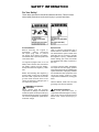
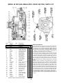
Electronic Service
Manuals
This electronic document is provided as a service to our customers.
We do not create the contents of the information contained in this document. Should you have detailed questions pertaining to the information
contained in this document, you may contact Michco, or the manufacturer which provided the original information in this electronic deliverable. Michco’s only part in this electronic deliverable was the electronic
assembly process. By providing this manual on line we are not guaranteeing parts availability.
You may contact Michco through the following methods:
Phone (517) 484-9312 or (800) 331-3339
2011 N. High St. -- Lansing, Michigan -- 48906
Fax: (517) 484-9836
Email: [email protected]
Web site: www.Michco.Com
Parts Web site: www.FloorMachineParts.Com
Order Parts on Line at:
www.FloorMachineParts.Com
Directly to Parts & Service:
By Email: [email protected]
By Fax: (517) 702-2041
By Voice: Use numbers above.
Serving the Cleaning Industry Since 1922
Notice: All copyrighted material remains property of original owners, all trademarks are property of respective owners.
Manuals are subject to Manufacturer’s reproduction limitations. Originals or reproductions were provided by manufacturers
through a request. We make no warranty as to the correctness of information provided in this document and you assume
all risk. By placing these manuals on line we are not declaring our corporation to be an manufacturer authorized dealer or
provider, please check our web site for authorized manufacturers we represent.
Mirage®
Propane
Burnisher
OPERATION
Model: M220021H13
SERVICE
PARTS
CARE
TABLE OF CONTENTS
Page
1
Unpacking Instructions, User Tips
2-4
General Warning Information
5-6
Engine Set-Up
7
Operation
8 - 10
General Maintenance Information
11 - 12
Trouble Shooting
13 - 18
Engine Specifications
19
Warranty Information
Back Cover
Warranty
UNPACKING INFORMATION
INSPECTION
Carefully unpack and inspect your Burnisher for shipping damage. Each unit is tested and thoroughly inspected before
shipment and any damage is the responsibility of the delivering carrier who should be notified immediately.
ENGINES
Engines are shipped with oil & coolant, if applicable. Refer to engine manual for correct weight and quantity. Briggs Vtwin 16 hp, Briggs 14 hp single cylinder, Kawasaki. Before starting engine check all levels. Do not overfill.
PROPANE TANK
The tank supplied with this equipment is a vertical vapor withdrawal 20 lb. tank. Do not overfill. Fill tank to 80% of rated
capacity. Safety fill, Aluminum unpolished, polished, and steel. All propane tanks are equipped with this special warning
sticker. Please read.
WARNING:
Vapor withdrawal tank weight fill only! Failure to weight fill tank will void
warranty and cause damage to propane components! Tare weight is stamped
on the tank.
USER TIPS
• Allow only qualified and trained personnel to operate a • Always check fuel system for leaks with soapy water.
Minuteman Propane Buffer.
(Hoses, regulators, connections)
• Always maintain your Minuteman Propane Buffer, follow • Never smoke while operating or working on propane buffer.
operating and maintenance instructions.
• Do not attempt to change a pad while buffer engine is
• Always check oil level before starting.
running.
• Always keep accurate records of maintenance and service • Keep hands, feet, hair, clothing, etc. away from buffing
in a maintenance log book.
pad, pulleys, and any other moving parts on equipment.
• Never overfill a propane fuel tank. Be sure to follow safety • If you smell gas, do not touch any electric switch,
instructions for venting overfilled tanks in safety section
extinguish any open flame and contact your gas supplier,
in this manual.
and open windows.
• Never leave machine unattended with engine running.
• If there is any smell of propane fuel, check immediately
for leaks and shut off tank at valve.
• Never change or alter fuel system unless authorized by
Minuteman International Inc. Service Department.
• Do not store any other flammable liquids or vapors in the
vicinity of propane storage area, machine storage area or
• Always keep nuts and bolts tightened and hose
any other appliance.
connection snug.
• Always clean recoil dust filters after 1 hour of use, and • Do not place flammable objects such as matches, fuel,
etc., close to the engine while it is running.
keep propane buffer clean.
• Always store propane tank outside in an approved, • Never attempt to repair a propane fuel tank by yourself.
Tanks can only be repaired by a Department of
secured, and tamper proof enclosure to provide safety
Transportation authorized facility.
from vandalism and accidents.
• Never use a non-UL listed fuel tank on your propane buffer. • For repairs or adjustments on your Propane Buffer use
only an authorized Minuteman Service Center.
• Always operate your propane buffer, with exhaust (muffler)
! CAUTION Visible escaping gas vapor is extremely
pointed away from merchandise, furniture, etc. Heat from
exhaust may cause damage.
cold (ICE). Degrees (-44) avoid contact.
• Never use a spray buff product over top of the engine.
! CAUTION Propane gas is heavier than air. The gas
This could cause damage to engine if product got into will settle to the lowest possible area and build upwards.
cooling system.
! CAUTION Build-up of propane vapor in any enclosed
• For all engine repairs refer to the engine manual included
area, can cause an explosion if ignited. Operate only in
with this parts and instruction book.
well-ventilated areas.
1
SAFETY PRECAUTIONS
Before operating the engine, read the Operator’s Manual FUEL SYSTEM
and become familiar with it and the equipment. Safe and • DO NOT fill fuel tanks while engine is running.
efficient operation can be achieved only if the equipment is • DO NOT smoke or use an open flame in the vicinity of
the engine or fuel tank. Internal combustion engine fuels
properly operated and maintained.
are highly flammable.
The following symbols, found throughout this manual, alert
•
Fuel line must be LP approved, adequately secured, and
you to potentially dangerous conditions to the operator,
free from leaks. Piping at the engine should be approved
service personnel, or the equipment.
flexible line. Do not use copper piping for flexible lines as
! DANGER This symbol warns of immediate copper will harden and become brittle enough to break.
hazards that will result in severe personal injury or • Be sure all fuel supplies have a positive shut-off valve.
death.
PROTECT AGAINST MOVING PARTS
• Do not wear loose clothing in the vicinity of moving parts,
! WARNING This symbol refers to a hazard or unsafe such as PTO shafts, flywheels, blowers, couplings, fans
belts, etc.
practice that can result in severe personal injury or
•
Keep your hands away from moving parts.
death.
This symbol refers to a hazard or unsafe EXHAUST SYSTEM
practice that can result in personal injury or product or • Exhaust products of any internal combustion engine are
toxic and can cause injury, or death if inhaled. When
property damage.
operating the engine in a confined area, make sure the
ventilation system is operating properly.
Fuels, electrical equipment, batteries, exhaust gases and
•
DO NOT use exhaust gases to heat a compartment.
moving parts present potential hazards that can result in
•
Make sure that your exhaust system is free of leaks.
severe personal injury. Take care in following these
Make sure that exhaust manifolds are secure and are
recommended procedures. All local, state and federal codes
not warped by bolts unevenly torqued.
should be consulted and complied with.
! CAUTION
EXHAUST GAS IS DEADLY!
Exhaust gases contain carbon monoxide, a poisonous gas
that can cause unconsciousness and death. It is an
odorless and colorless gas formed during combustion of
hydrocarbon fuels. Symptoms of carbon monoxide
poisoning are:
GENERAL
• Provide appropriate fire extinguishers and install in
convenient locations. Use an extinguisher rated ABC by
NFPA.
• Make sure that all fasteners on the engine are secure
and accurately torqued. Keep guards in position over fans,
driving belts, etc.
• If it is necessary to make adjustments while the engine
is running, use extreme caution when close to hot
exhausts, moving parts, etc.
• Used engine oils have been identified by some state or
federal agencies as causing cancer or reproductive
toxicity. When checking or changing engine oil, take care
not to ingest, breathe the fumes, or contact used oil.
• Do not work on this equipment when mentally or
physically fatigued, or after consuming any alcohol or
drug that makes the operation of equipment unsafe.
•
•
•
•
Dizziness
Headache
Weakness and Sleepiness
Throbbing in Temples
• Vomiting
• Muscular Twitching
If you experience any of these symptoms, get out into fresh
air immediately, shut down the unit and do not use it until it
has been inspected.
The best protection against carbon monoxide inhalation is
proper installation and regular, frequent inspections of the
complete exhaust system. If you notice a change in the
sound or appearance of exhaust system, shut the unit down
immediately and have it inspected and repaired at once by
a competent mechanic.
KEEP THE UNIT AND SURROUNDING AREA CLEAN
• Make sure that oily rags are not left on or near the engine.
• Remove all unnecessary grease and oil from the unit.
Accumulated grease and oil can cause overheating and
subsequent engine damage and present a potential fire
hazard.
2
SAFETY INFORMATION
For Your Safety!
These safety precautions should be followed at all times. Failure to follow
these safety precautions could result in injury to yourself and others.
Explosive Fuel
LPG is extremely flammable and is
heavier than air and tends to settle in
low areas where a spark or flame could
ignite the gas. Do not start or operate
this engine in a poorly ventilated area
where leaking gas could accumulate
and endanger the safety of persons in
the area.
Accidental Starts!
Before servicing the engine or
equipment,
always
disconnect
the spark plug lead to prevent
the engine from starting accidently.
Ground the lead to prevent sparks that
could cause fires.
On engines equipped with a 12-volt
battery and/or electric start, disconnect
the battery cables from the battery.
Always disconnect the negative (-) cable
first.
To insure personal safety, installation
and repair of LPG fuel supply systems
must be performed only by qualified LPG
system technicians. Improperly installed
and maintained LPG equipment could
cause fuel supply system or other
components to malfunction, causing gas
leaks.
Before disconnecting the negative (-)
ground cable, make sure all switches
are OFF. If ON, a spark will occur at the
ground cable terminal which could
cause an explosion if hydrogen gas or
fuel vapors are present.
Observe federal, state and local laws
governing LPG fuel and systems.
WARNING: Over-speed is
Hazardous!
Never tamper with the govenor
components or settings to increase the
maximum speed. Severe personal injury
and damage to the engine or equipment
can result if operated at speed above
maximum ratings.
!
! CAUTION: High Voltage!
Never touch electrical wires or
components while the engine is running.
They can be sources of electrical shock
which could cause severe injury or
burns.
3
SAFETY INFORMATION CONTINUED
Lethal Exhaust Gases!
Engine exhaust gases contain
poisonous carbon monoxide. Carbon
monoxide is odorless, colorless, and
can cause death if inhaled. Avoid
inhaling exhaust fumes, and never run
the engine in a closed building or
confined area.
Rotating Parts!
Keep hands, feet, hair, and clothing
away from all moving parts to prevent
injury. Never operate the engine with
covers, shrouds, or guards removed.
WARNING
The 120V A.C. starter is
equipped with a three-wire
power cord and plug, and is
designed to operate on
120V A.C. household current. The starter must be
properly grounded at all
times to avoid the possibility of injury or death from
electrical shock. Always use
a three-wire ground fault interrupted system. 715432
4
Hot Parts!
The crankcase, cylinder head, exhaust
system, and other components can
get extremely hot from operation. To
prevent severe burns, do not touch
these areas while the engine is running
- or immediately after it is turned off.
Never operate the engine with heat
shields or guards removed.
ENGINE SET-UP
PRE-START CHECKS
Inspect the engine visually. Check for loose or missing parts Refer to Engine Owners Manual for the crankcase oil
and any damage that may have occurred in shipment.
capacity.
Starting the engine without oil will Single-grade oil is preferable when temperatures are
! CAUTION
result in severe engine damage. Add oil prior to starting consistently -over 30°F (0°C). Multigrade oils are best when
the engine.
wide temperature variations are anticipated.
CRANKCASE OIL RECOMMENDATIONS
! WARNING Crankcase pressure can blow out hot
Use premium quality motor oil with the API (American oil, that can cause severe personal injury. Do not check
Petroleum Institute) designation SG on the container. Figure the oil level while the engine is running.
1 shows the recommended oil weight for the temperature
range that the engine will be operated in. Make sure the
! CAUTION Excess oil can cause high oil
engine oil weight is correct for the expected temperature
range.
consumption, high operating temperatures, and oil
foaming. Do not overfill the crankcase.
TABLE 1 FIGURE 1
5
PROPANE BURNISHER SET-UP
CHECK OIL
STARTING AND OPERATION PROCEDURE
Refer to engine manual for the type of oil, and instructions for
checking oil. It is important to note engine manufacturers differ
in the way oil is checked. Add oil if needed. Refer to Page 10.
CAUTION: NEVER ALLOW MACHINE TO RUN FOR MORE THAN
10 SECONDS IN ONE SPOT OR DAMAGE WILL OCCUR TO
THE FLOOR!
1.
Check oil and fuel levels. Make sure oil and propane tank
is not overfilled.
2. Check and clean recoil dust filter and carburetor filter.
Make sure air filter is free of dust and debris. Never run
buffer for more than 1 hour without cleaning air filter.
Change filters when necessary.
PROPANE TANK INSTALLATION
Buffer is supplied with 20 lb., 5 gallon capacity D.O.T. and U.L. 3. Check pad and pad assembly, to make sure pad is
centered and clean, and look for any problems with pad
listed tank. DO NOT OVERFILL. Overfilling will cause regulator
driver. To do this turn machine over on its right side.
to freeze. This could cause damage to your equipment. Hold
tank in place by clamping the toggle assembly to the tank 4. Check belt tension, again turn machine over on its right
side and squeeze belt together. Belt should depress
band around the tank. Adjustments to the toggle assembly are
between 1/4 and 1/2 inch. To change see maintenance
made by screwing toggle in or out on the toggle clamp. Connect
instructions. (Page 13)
fuel hose to the tank valve by turning coupling to the right
5.
Open propane service valve, turn counter-clockwise to
(clockwise). Hand tighten only, making sure not to cross thread
open.
the coupling.
6. Tilt machine backward with pad off the floor, move bail to
IDLE position. Never start machine with pad on the floor.
REMOVING TANK
To loosen turn coupling to the left (counter clockwise). Undo 7. With 115V starting system, plug in adapter to wall outlet
and the starter box. Turn key to the on position and push
the tank strap, remove tank and store in approved area. Do not
button on start box. If machine fails to start allow
store tank with machine in the janitor’s closet.
approximately 30 seconds between tries, never engage
starter more than 10 seconds at a time.
INSTALLATION/CHANGING PAD
a. Never start buffer with pad on the floor, this will
1. With engine off, turn the machine over on the operator’s
cause the starter to burn out prematurely!
RIGHT side (starter side) for the Briggs & Stratton models.
b. Never use starting fluids or any other forms of
This can be easily done by pushing down on the right side
flammable substance to assist the engine in
of the handle with some force while the machine is tilted
starting!
back.
8. Allow engine to warm up and run at normal operating
2. Remove the center cup retainer and carefully pull old pad
speed before engaging pad with floor. Make sure pad is
off the pad driver assembly.
off the floor before engaging the clutch. Once machine is
3. Inspect the pad holder for cracks or damage. Replace if
at normal operating speed and clutch is engaged, start
necessary. NOTE: A DAMAGED PAD HOLDER ROTATING
walking and slowly lower the machine to the floor and
AT HIGH SPEEDS MAY BE AN EXTREME HAZARD IF IT
begin burnishing the floor.
SHOULD COME APART.
9. Machines with mechanical clutches: NOTE: Never engage
4. Pull center from new pad, enter pad on pad holder and
clutch with pad on floor. Once machine has reached
secure with center cup retainer.
normal operating speed clutch is engaged automatically
5. Press pad on to the pad driver assembly making sure
at 2400 engine RPM and start burnishing. Start burnishing
pad fits inside the lip of the pad driver assembly, to prevent
when pad has reached top speed.
pad from elongating, attach center cup retainer.
10. Always burnish on the right hand, so exhaust fumes are
6. Return machine to the upright position.
blown to the inside of the aisle. Be careful exhaust fumes
and muffler are extremely hot and will damage
TRANSPORTATION
merchandise. NOTE: Do not expose skin to muffler or
When transporting a propane powered floor machine with the
manifold - extreme heat, will burn.
fuel cylinder attached, the cylinder should be securely fastened 11. For normal stops of the machine, turn propane service
with service valve closed and coupling not attached. The
valve clockwise, to starve the engine of its fuel. Do not
machine should be secured to the vehicle to avoid movement.
stop machine by using the bail or ignition key, you can trap
Tanks separate from the machine should be secured to avoid
fuel in the lines, which can cause a backfire and cause
movement. NEVER STORE MACHINES WITH TANKS IN AN
damage to the engine. NOTE: In case of emergency
ENCLOSED VAN OR TRAILER. ALWAYS CHECK TANKS FOR
always turn ignition key off. NOTE: Machines without
OVERFILL BEFORE TRANSPORTATION.
clutch, the pad starts to rotate immediately when engine
starts. Pad stops rotating when engine is off! No clutch!
HANDLE ADJUSTMENT
Adjust handle by loosening nuts and bolts on each side of
handle. Push handle handle in or pull out to desired position
and reinstall nuts.
6
OPERATION INFORMATION
ENGINE BREAK-IN
Engine break-in as a result of proper care during the first
hours of operation of a new or rebuilt engine results in the
ideal fitting of all internal moving metal parts, which is
essential for top engine performance. For controlled engine
break-in.
1. Operate the equipment as it is intended to be operated.
However, for the first 3 hours, if possible, operate the
equipment at about half the available engine power,
occasionally operating at full engine power for brief
periods. Also, if possible, avoid prolonged low-speed,
low-power operation during engine break-in.
2. Proper engine oil is especially critical during break-in
because of the higher engine temperatures that can be
expected. See RECOMMENDED ENGINE OIL.
Change the oil if it is not appropriate for the ambient
temperatures during the break-in periods. See Table 1,
Figure 1 Page 6.
3. Check the oil level twice a day or after every 4 hours of
operation during the first 24 hours of operation.
4. Change the oil and oil filter after the first 5 hours of
operation.
After engine has reached operating temperature while pad
is still off the floor. Before lowering burnishing head, adjust
throttle to operating speed. After slowly lowering machine
to floor, place hands lightly on the handle and allow the
machine to create the floor pressure. Bearing down and
pushing hard will lead to premature belt problems and
operator fatigue. For smoother turns and greater
maneuverability, buff aisles from the right side first.
CAUTION: DO NOT RUN MACHINE FOR MORE THAN 15
SECONDS IN ONE SPOT OR BURNING WILL OCCUR.
IDLING AND STOPPING THE MACHINE
If for any reason the machine needs to be idled for short
periods, simply tilt machine back on its rear caster and
release throttle bail into Idle Position. Machine will now idle
safely. (CAUTION: DO NOT IDLE BUFFER ON REAR
CASTER FOR MORE THAN TWO MINUTES. This will
raise the emissions level.)
To stop machine tilt back on rear caster, turn valve on
propane tank off, and allow fuel in the lines to be used up.
FOR EMERGENCY SHUT OFF ONLY: turn off ignition
OPERATION IN DUSTY CONDITIONS
switch. Electric start models: use emergency stop switch
1. Keep the engine cooling fins and flywheel air inlet screen on right side of control panel.
and precleaner (filter) clean.
2. Perform air cleaner maintenance more often than STORAGE
normal - as required.
Only authorized and properly trained personnel should have
3. Change the engine oil more often than normal. See access to propane tanks and machine.
Table 2, Page 10.
Making sure tank valve is closed, remove tank from buffer.
Local Fire Codes may require storing tank in separate
OPERATION IN HOT WEATHER
location. We recommend this, as well as following
Pay particular attention to the following items when Local Fire Codes.
operating the engine in temperatures above 100°F (38°C): Store machine and tank away from objects that may fall
1. Keep the engine cooling fins and flywheel air inlet screen and damage them.
and precleaner (filter) clean: See to it that nothing Never store tank or buffer near open flame or heat producing
obstructs air flow to and from the engine.
devices.
Make sure machine is cleaned properly prior to storage.
2. Check the oil level more frequently.
3. Change the oil more often than normal. See Table 2, To prevent damage pad holder, the pad SHOULD remain on
machine during storage.
Page 10.
4. Make sure the engine oil viscosity is appropriate for
the ambient temperature and change the oil if EMERGENCY STOP
Turn ignition key to OFF position.
necessary. See Table 1, Figure 1 page 6.
Units with emission control device and clutch. Release bail
on handle to activate kill switch.
OPERATION IN COLD WEATHER
Pay particular attention to the following items when
operating the engine in temperatures below freezing.
Make sure the engine oil viscosity is appropriate for the
ambient temperatures and change the oil if necessary. See
Table 1. If the temperature drops before you have the chance
to change the oil, warm up the engine by moving the
equipment into a heated space before attempting to start
the engine or change oil.
7
MAINTENANCE SCHEDULE
PERIODIC MAINTENANCE SCHEDULE
Following the maintenance schedule and using the engine
properly will result in longer engine life, better performance
and safer operation. Perform each maintenance procedure
after the number of operating hours indicated. These service
intervals are recommended for normal operating conditions.
For operation in hot or dusty conditions, service the engine
more frequently. Neglecting routine maintenance can result
in premature engine failure.
For any abnormalities in operation, unusual noises from
the engine or accessories, loss of power, overheating, etc.,
contact your nearest Engine Service Center.
Refer to the following Maintenance Procedures section for
routine maintenance procedures.
TABLE 2. PERIODIC MAINTENANCE SCHEDULE
AFTER EACH CYCLE OF INDICATED HOURS
SERVICE THESE ITEMS
1
8
Recoil Dust Filter
X
100
200
X
X2
Service Air Cleaner Element and Element Wrapper
Change Crankcase Oil
X3
Replace Oil Filter (Onan, Kawaski Models)
X3
X
X
X2
X
Clean Cooling Fins
Clean Spark Arrester
X4
Check Valve Clearance
1
2
3
4
50
X1
Inspect Engine Generally
Check Oil Level
25
X
Replace Air Cleaner Element
X2
Check or Replace Spark Plug
X
- Check for fuel leaks. With engine running, visually and audibly check exhaust system for leaks.
- Perform more often when running under severe operating conditions.
- Required for initial break-in only.
- Required for initial 100 hours, 200 hour interval thereafter. For detailed maintenance, refer to the Engine Service Manual.
! WARNING Breathing exhaust gases can result in severe personal injury or death. Do not use air cleaner,
exhaust elbow, or connecting parts as a supporting step. Damage to these and connecting parts can cause an
exhaust leak.
8
MAINTENANCE PROCEDURES
4. Check the engine oil level. The equipment must be
Accidental starting of the engine can
parked on a level surface and the engine stopped. To
result in severe personal injury or death. Disconnect
get an accurate reading, wait a minute or so to allow
the 110 VAC power cord from the starter switch junction
the oil to settle in the crankcase if the engine has been
box or disconnect the negative (-) battery cable on 12
running.
VDC starter models. Also disconnect the spark plug
wire while servicing the engine, controls, or associated ENGINE MAINTENANCE
1. Cooling Fin Maintenance: Remove the blower housing
equipment.
and other cooling shrouds. Clean the cooling fins as
HOURLY CHECK
necessary using compressed air or pressure washer.
Due to the large amount of dust that can be encountered in
Reinstall all housings and shrouds.
floor care applications, the recoil dust filter should be
2. Head Bolt Maintenance: Refer to Engine Manufacturer’s
checked after each hour of operation. Remove and clean
Service manual.
the filter.
BELT MAINTENANCE
DAILY CHECKS
NOTE: To inspect the belt it is necessary to turn the machine
The operator should make a complete visual and audible
over. The machine should be turned to the operator’s right
inspection of the engine daily. Check the following before
side for all Briggs & Stratton models. If the belt is badly
starting the engine for the first time each day.
cracked or worn, it should be replaced. To check for the
1. Check all fuel lines and fitting for possible leakage.
proper tightness, squeeze the belt together. The belt should
2. Check crankcase oil level with the engine off. If engine
depress between 1/4 and 1/2 inch. To change belt follow
has been run, allow a minimum of 10 minutes for the
these instructions:
oil to drain down before checking. Check oil level with
• Turn burnisher over on the right side.
machine in operating position. Do not operate engine
• Remove the pad holder by holdng the end of the
with the oil level below the ADD mark or above the FULL
shaft on the top of the machine with a 3/4 inch
mark.
wrench and turn the pad holder counter-clockwise.
3. Inspect exhaust system for possible leakage and
• Using the 3/4 inch wrench to turn the end of the
cracks. Locate leaks in muffler and piping while the
spindle shaft on the top of the machine while
engine is operating. Repair leaks immediately.
removing the old belt from the spindle pulley.
4. Inspect air cleaner system for leaks. Make certain all
• Check engine pulley for correct alignment with the
clamps and fittings are tight and free of potential leaks.
spindle pulley. Check hardware attaching pulleys
5. Check the engine cooling system to make sure the
for correct tightness.
cooling fins and ducting area are clean. Remove dust,
• Install the new belt onto the engine pulley.
dirt or oil from the cooling surfaces.
• Reinstall the new belt onto the spindle pulley using
DAILY (8 HOUR) MAINTENANCE
the 3/4 inch wrench to turn the spindle clockwise.
The operator should check the following before the first
Make sure the belt is correctly placed on the idler
start of the day and after every eight hours of operation:
pulley.
1. Inspect fuel lines and fittings for leaks. Repair leaks
• Check belt for correct operation.
immediately.
• Check all hardware for correct tightness.
2. Look and listen for exhaust system leaks while the
FUEL SYSTEM
engine is running. Look for cracks and severe rusting
The fuel system works from vacuum created by the engine
in the muffler and tailpipe. Have all leaks repaired before
running. Turning the cylinder service valve on pressurizes
continuing to operate the equipment.
the system for flow to the carburetor once the engine starts
! CAUTION Hot exhaust parts can cause severe to crank.
burns. Allow the engine time to cool before 1. Engine Dust Filter: FAILURE TO MAINTAIN A CLEAN
servicing the exhaust system.
ENGINE FILTER MAY CAUSE THE EXHAUST
3. Check the engine for dirt and debris and clean the
EMISSIONS TO ELEVATE TO DANGEROUS LEVELS.
flywheel air inlet screen and cylinder cooling fins as
ALSO, IT WILL CAUSE THE ENGINE TO OVERHEAT,
necessary. On floorcare equipment engines, remove
AND EVENTUALLY DAMAGE THE ENGINE. The
the cooling air precleaner element every 4 to 8 hours of
engine dust filter should be cleaned each hour and
operation and wash it in warm water and mild detergent.
after each use by shaking out the dust and then rinsing
Rinse it thoroughly and let it dry before reusing it. Do
with soapy water. Allow filter to air dry, do not wring
not oil the element.
out water, this could damage the filter, (squeeze out).
2.
Fuel System Adjustment:The carburetor and regulator
! CAUTION A clogged flywheel air inlet precleaner
have been pre-set at the factory and do not require any
or screen or dirty cooling fins can cause overheating
modification. Only authorized, trained personnel should
and engine damage. Keep the cooling fins and air inlet
work on the fuel system of a propane buffer.
screen clean.
! WARNING
9
MAINTENANCE PROCEDURES
NOTE: N.F.P.A. rule 58 8-1.4 states, “In the interest of
safety, each person engaged in installing, repairing,
filling, or otherwise servicing an LP-Gas engine fuel
system shall be properly trained in the necessary
procedures”.
3. Hose and Fuel Connections: Inspection: Check for gas
leaks by using a soapy water solution around all
connections with service valve turned on so the fuel
system is pressurized. Inspect all hoses for abrasions
and other signs of wear. Replace all damaged and worn
hoses. Fixing Leaking Joints: Uncouple bad joint, clean
joint and apply pipe sealing compound (use a Loctite
Pipe Sealant with Teflon or equivalent) to clean joint.
Re-couple the joint, tighten plus 1/2 turn. Recheck for
leaks.
4. Carburetor Air Filter: NOTE: Failure to service and clean
carburetor air cleaner may produce excessive carbon
monoxide emissions.
• Remove cover from the air cleaner.
• Remove foam pre-cleaner and use the same
procedure for cleaning the foam pre-cleaner.
• Rinse in mild detergent and squeeze out excess
water, do not wring out.
• Clean filter seal, making sure no dust is allowed
in the carburetor inlet.
• Inspect paper element. Replace if dirty, bent or
damaged.
• Install the clean paper element, pre-cleaner, and
attached air cleaner cover.
If the oil level is low, add API Class SG or SH oil (also SG/
CD, SG/CE, SH/CD or SH/CE) having an SAE viscosity
grade appropriate for the expected temperatures, as
indicated by Table 1.
DO NOT FILL TO A LEVEL ABOVE THE FULL MARK ON
THE DIPSTICK. Drain the excess oil if too much has been
added.
! CAUTION Too much oil can cause high oil
consumption, high operating temperatures and oil
foaming. Too little oil can cause severe engine damage.
Keep the oil level between the Full and Add marks on
the dipstick.
Reinstall the dipstick and cap after checking or adding oil,
turning it clockwise until it is secure.
OIL CHANGE
!
WARNING
Hot crankcase oil can cause burns if it
contacts the skin. Wear protective clothing and keep
fingers and hands clear when draining oil.
Used oil is harmful to the environment. Pour used oil into a
sealed container and deliver it to the nearest recycling
center or automotive service station.
CHANGING THE OIL
1. Run engine for 5 minutes to warm oil, then stop engine
by closing the service valve on the tank. Turn the key
to the off position.
2. Locate the oil drain located the right side of the engine
at its base. Remove the cap on the oil drain tube by
turning counter clockwise with a wrench.
3. Allow oil to drain completely into the receptacle.
4. Replace the cap by turning clockwise.
5. Remove oil fill cap. Always refer to the Engine Manual
for recommended oil and amount.
6. Check oil level with dip stick in oil fill cap. Add additional
oil if necessary. NOTE: TO CHECK OIL ON THE
BRIGGS & STRATTON MODELS, SCREW THE CAP
IN AND OUT AGAIN. ALWAYS MAKE SURE THE
MACHINE IS SITTING LEVEL WHEN CHECKING OIL.
7. Replace fill cap. Hand tighten only.
10
OIL FILL CAP AND DIPSTICK
TROUBLESHOOTING
Table 3 provides basic troubleshooting guidance. If you fail to
! WARNING Hot engine parts can cause severe burns.
resolve the problem after taking the corrective actions
Always allow the engine time to cool before performing any
suggested, contact the equipment or engine dealer.
maintenance or service.
! WARNING Many troubleshooting procedures present
hazards that can result in severe personal injury or death.
Only qualified service personnel with knowledge of fuels,
electricity, and machinery hazards should perform service
procedures. Review Safety Precautions.
TABLE 3. TROUBLESHOOTING
Problem
Corrective Action
1.
The engine fails to crank
a. Not pluged into outlet.
2.
The engine cranks slowly.
a. Change engine oil having the proper viscosity for ambient temperature.
See table 1.
b. Check oil level for overfilling.
c. Check starter electrical connections.
3.
The engine cranks but fails
to start.
a. Check the fuel tank or LPG container and fill as necessary.
b. Check, and if necessary, reconnect the fuel line to the vapor-withdrawal
fitting on the LPG container.
c. Open any closed fuel shut-off valve (check keg in on position).
d. Check engine oil level and add oil as necessary.
e. Service the air cleaner.
f. Clean the air precleaner (floorcare engines).
g. Replace the spark plugs.
4.
The engine runs and
then stops.
a. Check the fuel tank or LPG container and fill as necessary. On cold days
the LPG container may have to be kept at least half full to provide the rate
of vaporization necessary to keep up with the engine fuel demand.
b. Check, and if necessary, reconnect the fuel line to the vapor-withdrawal
fitting on the LPG container.
c. Check the engine oil level and add oil as necessary. Drain excess oil if the
level is above the dipstick FULL mark.
5.
The engine exhausts
black smoke.
a. Service the air cleaner.
6.
The engine misfires.
a. Replace the spark plugs.
11
TROUBLE SHOOTING
ENGINE WILL NOT START
EXCESS VIBRATION
CAUSES:
No fuel, blown head gasket, bad ignition coil, dirty air
cleaner, wires broken or disonnected, engine overload,
insufficient vacuum, bag spark plug, fuel system out of
adjustment.
CAUSE:
Engine overload, loose bolts on engine or deck of unit, low
fuel level, dirty air filters, faulty spark plug, pad not centered.
SOLUTION:
Refer to engine manual for servicing and instruction.
SOLUTION:
Refer to engine manual for servicing and instruction.
MACHINE PULLS TO ONE SIDE
HARD TO START
CAUSE:
Bent wheel bracket, wheel is wearing too much on one
side.
CAUSES:
Kinked fuel line, dirty air filter, bad spark plug, blown head
gasket, low oil, engine overload, carburetor needs SOLUTION:
adjustment, regulator needs adjustment, insufficient Check for bent bracket or worn wheel.
vacuum, improper timing, coil or valves need adjusting.
SOLUTION: Refer to engine manual for servicing and MACHINE “BOGS DOWN” WHEN IN USE
instruction.
CAUSE:
Too much pressure or operator is bearing down too hard.
ENGINE LACKS POWER
Dirty air filters.
CAUSES:
Head gasket leaks, governor improperly adjusted, check
air filter, insufficient vacuum, bad spark plug, no
compression worn rings, improper valve clearance, kinked
fuel line, improper oil level.
SOLUTION:
Follow proper operating instructions, let machine operate
on its own weight, do not apply upward pressure to handle
of machine.
ENGINE STOPS RUNNING
SOLUTION:
Refer to engine manual for servicing and instruction.
CAUSE:
Out of fuel, faulty spark plug, low oil, dirty air filters, high
exhaust emissions.
SMELL OF BURNED RUBBER
CAUSE:
Belt out of adjustment.
SOLUTION:
Refer to Maintenance Procedures.
SOLUTIONS:
Refer to engine manual for servicing and instruction.
HIGH FUEL CONSUMPTION
CAUSE:
Dirty air filters, dirty air cleaners.
SOLUTION:
Keep engine and air filters clean.
12
ENGINE 13HP HONDA
13
PARTS LIST for 13HP HONDA
Item
1
2
3
4
5
6
7
8
9
10
11
12
13
14
15
16
17
18
19
20
21
22
23
24
25
26
27
28
29
30
31
32
33
34
35
36
37
38
39
40
41
42
43
44
45
46
47
48
49
50
51
52
53
54
55
56
57
58
59
60
61
62
63
64
65
66
Part No.
Qty.
360108
1
712638
2
711503
4
515-10-24
2
220131
1
715343
1
220118
1
220393
1
711505
4
220056
2
711373
8
220385
1
711515
4
711439
4
711506
6
713031
2
220482
1
220021PTD 1
711544
4
711203
4
713043
4
831306
1
220221
1
350280
1
220246
1
220483
1
220237
1
220245
1
342430
1
450076
2
220269
1
220192
1
220070-1
1
220065
1
62-252-A
1
715501
1
715245
1
740539
1
715192
1
715242
1
741056-1
2
741056
1
829052
2
711721
2
220112
1
55-161-A
2
220343
1
711374
2
220338
1
220339
1
711207
4
713036
2
711380
4
711213
4
712538
2
255045
1
220328-1
1
711301
2
711551
2
220270
1
711225
4
711388
2
711504
2
713042
4
711439
4
715432
1
Description
Handle Sleeve
Nut-Hex 10-24 Nyloc
WSR-Flat #10
SCR-RD HD 10-24 x 1 1/2
Buckle TB2-61
Decal, Propane Warning
Propane Tank Steel
Battery Cover Weldment
WSR-Flat 1/4
Felt 2 x 10
Nut-Nyloc 1/4-20
Engine 13 HP Prop Honda
WSR-Flat .406 x .812 x .06
Nut-Wizz 3/8-16
WSR-Flat 5/16
BLT-HH 5/16-18 x 2.00
Starter Assy, 115V Tecumseh
Casting
WSR-Helical 1/4
BLT-HH 1/4-20 x .62
BLT-HH 3/8-16 x 1 1/4 #5
90o Elbow Street 1/4-1/4
Electric Lockoff Assy
Hose Barb 1/8 x 1/8 NPT
Elbow-90 1/8mpt x 1/8fpt
Regulator Beam T60-E
Regulator Bracket
Elbow-45 3/8mpt x 3/8fpt
Hose Barb
Crimp Clamp
Fuel Hose - 3/8 ID x 30”
Tank Frame Weldment
High Pressure Hose
45° Male Elbow 1/4 x 3/8
Connector - Female
Decal - Made in USA
Decal - Ignition Switch
Hour Meter
Decal - Dashboard
Decal - Propane Warning
Key-Ignition, Replacement
Keyswitch w/Ground
Nylon Bushing
Retaining Ring
Torsion Spring
WSR-Special
Handle
Nut-Nyloc 5/16
Handle Bracket LH
Handle Bracket RH
BLT-HH 1/4-20 x 1.00
BLT-HH 5/16-24 x 1.25 BZ
Nut-Nyloc 3/8-16
BLT-HH 1/4-20 x 1.62
SCR-MC 10-24 x 1.75 SS
Spacer, .19 x .37 x .47
Cable, Lined
Nut-Hex 6-32
WSR-Internal LOC #6
Bail, Throttle LH Cable
BLT-HH MM6 x 1.0 x 20mm
Nut-Hex 6mm
WSR-Flat 1/4 SS
BLT-HH 3/8-16 x 1.00 #5
Nut-Flanged Wizz 3/8-16
Decal, GFCI Warning
14
ENGINE 13HP HONDA
15
PARTS LIST for 13HP HONDA
Item
Part No.
Qty.
1
2
3
4
5
6
7
8
9
10
11
12
13
14
15
16
17
18
19
20
21
22
23
24
25
26
27
28
29
30
31
32
33
34
35
36
37
38
39
40
41
42
43
44
45
46
711545
6
711354
1
711546
1
430029
1
711506
6
713165
4
220330
2
220049
2
220340
2
713049
2
220198
1
72-179-A
1
833621
1
220197
1
82-138-B-3
1
350242
1
60-716-24
1
712112
1
220040
1
77-81-A
1
220041
1
364-816
1
220010
1
220097
1
220019
6
760401
1
760402
1
220005
1
220020
12
220018
1
220022
1
220045
1
220044
1
711719
2
220003
1
220002
1
762093
2
220023MCH 1
220016
1
220119
1
828894
12
715385
1
220021PTD 1
55-161-A
2
711374
12
711380
2
Description
WSR-Helical 5/16
Nut-Acorn 3/8-16
WSR-Helical 3/8
Caster
WSR-Flat 5/16
SCR-FH SC 5/16-18 x 1.00
Wheel Bracket Weldment
Bushing .381 x .5 x 1.75
Wheel 6”
BLT-HH 3/8-16 x 2.75
Spacer
Spacer
Key 1/4 x 1/4 x 1.00
Pully-4.6 OD
Special Washer
Belleville Washer 7/16
BLT-HH 7/16-20 x 1.5
BLT-HH 1/2-13 x 2.75
Rotary Tensioner
Spacer
Belt Idler w/Bushing
Nut-Nyloc 1/2-13
Belt Tensioner Assy.
V Belt BX44T (M220021K17,K17C)
Gimbal Spacer Disc
Center Cup
Center Cup Retainer
Metal Spinning (M220021K17,K17C)
BLT-Special Elevator
Gimbal Disc
Adapter
Split Tapered Bushing
Pulley
Retaining Ring, Ext. 1.00
Key, Woodruff 5/16 x 1
Shaft, Pad Driver
Bearing
Bearing Housing
Skirt (M220021K17,K17C)
Skirt Retainer (M220021K17,K17C)
Pop Rivet
Decal - Minuteman
Casting
WSR-Special
Nut-Nyloc 5/16
Nut-Nyloc 3/8-16
16
WIRING DIAGRAM 13HP HONDA
17
MODEL 50 DRY-GAS REGULATOR, CROSS SECTION, PARTS LIST
Item
Part No.
**
**
**
1
2
3
4
5
6
7
8
9
10
11
12
13
14
15
16
17
18
19
20
21
22
23
24
25
26
27
NS
60-RBK
60-RCK
60-RK
P3-13
50-1
2G-150
60-10A
60-7
60-8
60-31
60-32A
60-4
60-2B
103205-F
60-5
60-3
103210-FS
60-29A
60-15A
60-14
60-22A
60-23
103206-P
60-16
60-17
60-18
60-19B
60-28
400-21
PS-20A
103204-P
Qty.
1
1
1
1
1
1
1
1
1
1
2
1
1
10
1
1
1
1
1
4
1
1
1
1
1
1
1
2
Description
Kit, Rebuilding
Kit, Complete
Kit, Repair
Plug, 1/8” Pipe, Hex
1 1
Casting, Reg. Body
Gasket with 60-10A
Diaphragm, Primary
1 1
Cover, Primary
Spring, Primary
1 1
Retainer Spring
Cap, Retainer
Spring, Primary
1 1
Lever, Primary
1 1
Screw, Machine
2 2
Bridge Primary
Pin, Pivot
1 1
Screw with Lockwasher10 10
Orifice, Primary
1
Diaphragm, Vac Lock
1 1
Spring, Vac Lock
1
Diaphragm, Secondary 1 1
Cover, Secondary
Screw, Machine
4
Ring, Vac Lock
Spring, Machine
1
Pin, Pivot
1
Lever, Secondary
1 1
Orifice, Secondary
1
Spring, Idle
1
Screw, Idle
1
Screw, Machine
2
1
1
4
1
1
1
4
1
1
1
1
1
2
Order by Part No. NOT by Reference No
18
REGULATOR OPERATION
LP-gas vapor enters at point (A), then passes into primary area
(B) at point (28), where pressure is reduced from up to 250 p.s.i.
at the tank to 4 p.s.i. in area (B). Fuel pressure against diaphragm
(4) overcomes spring (6) and as movement increases, spring (9)
will close lever (10). The primary diaphragm breather (not shown
in drawing), is vented to secondary chamber so that rupture of
this diaphragm would direct fuel into the carburetor.
Fuel now moves through passage (E), past secondary valve (29)
into secondary area (C). As negative pressure (vacuum) is created
at carburetor venturi and is transmitted through dry-gas hose to
chamber (C) atmospheric pressure, exerted through vent hole
(G), forces down secondary diaphragm (18), secondary lever
(24) and spring (22). Fuel will flow in proportion to air velocity
through carburetor venturi, insuring an ideal mixture at all engine
speeds.
Whenever engine is operating, vacuum diaphragm (16) is down
against floor (H) and spring (17) is collapsed. The idle and starting
adjustment is made with tapered screw (27) which regulates the
whisker wire system (not shown), opening up secondary orifice
slightly (but only when vacuum diaphragm is drawn down). Very
little vacuum is needed to start this vacuum diaphragm travel; 0.2”
Mercury to start and 0.5” Mercury for full travel. The instant engine
stops rotating, loss of vacuum in section (D) releases diaphragm
(16), causing bumper (K) to push against secondary lever (24),
overcoming action of whisker wire and insuring 100% lockoff.
This patented Beam design will lock off primary pressures up to
five times in excess of normal, permits starting without priming or
choking.
WARRANTY INFORMATION
CARB SMALL ENGINE CERTIFICATION
MANUFACTURER: HONDA
INTERNATIONAL INC
ENGINE FAMILY:
WMNTS.4372K1
XMTRS.2492K3
XMTRS.4942K2
CALIFORNIA EMISSION CONTROL
SYSTEM WARRANTY STATEMENT
The California Air Resources Board and
Minuteman International, Inc. are pleased
to explain the emission control system
warranty on your 1998 and later utility
engine. In California, new utility and lawn
and garden equipment engines must be
designed, built and equipped to meet the
State’s stringent anti-smog standards.
Minuteman International, Inc. must
warrant the emission control system the
your utility equipment engine for the
periods of time listed below provided
there has been no abuse, neglect or
improper maintenance for your utility
equipment engine.
Your emission control system may
include parts such as the carburetor or
fuel injection system, the ignition system
and catalytic converter. Also included may
be hoses, belts, connectors and other
mission-related assemblies.
Where a warrantable condition exists,
Minuteman International, Inc. will repair
your utility equipment engine at no cost
to you including diagnosis, parts and
labor.
MANUFACTURER’S WARRANTY
COVERAGE
The 1998 and later utility and lawn and
garden equipment engines are
warranted for two years. If any emissionrelated part on your engine is defective,
the part will be repaired or replaced by
Minuteman International, Inc.
OWNER’S WARRANTY
RESPONSIBILITIES
As the utility and lawn and garden
equipment, you are responsible
for the performance the required
maintenance listed in your owner’s
manual. Minuteman International, Inc.
recommends that you retain all receipts
covering maintenance on your utility
equipment, but Minuteman International,
Inc. cannot deny warranty solely for
the lack of receipts or for your failure
to ensure the performance of all
scheduled maintenance. As the utility
equipment engine owner you should,
however, be aware that Minuteman
International, Inc. may deny you warranty
coverage if you utility equipment engine
or a part has failed due to abuse,
neglect, improper maintenance or Inc. is not liable for failure of warranted
unapproved modifications.
parts caused by the use of add-on
modified parts.
You are responsible for presenting your
utility equipment to a Minuteman Warranty service or repairs are available
International, Inc. distribution center as at all Minuteman International, Inc service
soon as the problem exists. The warranty centers that are franchised to service this
repairs should be completed in a engine.
reasonable amount of time, not to exceed
30 days.
Any Minuteman International, Inc.
approved replacement part may be
If you have any questions regarding your used in the performance of warranty
warranty rights and responsibilities, you maintenance or repairs on emissionshould contact Minuteman International, related parts and will be provided to the
Inc. at 1-800-323-9420. Minuteman owner without charge if the part is still
International, Inc. 111 South Rohlwing under warranty.
Road, Addison, IL 60101.
The owner is responsible for the
MANUFACTURER’S EXPLANATION OF performance
of
the
required
WARRANTY COVERAGE
maintenance, as defined in the
Minuteman International, Inc. owner’s
The engine manufacturer warrants to the manual for this engine.
original owner and each subsequent
purchaser that each subsequent SPECIFIC EMISSION-RELATED
purchaser that each new engine will be WARRANTED PARTS
free from manufacturing defects in
materials or workmanship under normal Fuel Metering System
use during a period of two (2) years from
Carburetor and internal parts
the date of delivery, provided it is operated
LPG Regulator
and maintained in accordance with Air Induction System
engine owner manual operating
Air intake manifold
instructions.
Air filter element
Air filter element-prefilter
Repair or replacement of any warranted Ignition System
part will be performed at no cost to the
Spark plug
owner at a warranty station. For the
Magneto
Minuteman International, Inc. repair Catalyst or Thermal Reactor System
station nearest you call 1-800-323-9420.
Exhaust manifold
Muffler
CARB SMALL ENGINE CERTIFICATION
Miscellaneous items used in above
MANUFACTURER: HONDA
systems
INTERNATIONAL, INC.
Fuel line and vacuum hoses, wire
ENGINE FAMILY:
harness, connectors & assemblies
WMNTS.4372K1
XMTRS.2492K3
To obtain warranty service, you must take
XMTRS.4942K2
your equipment together with proof of
original retail purchase date, at your
Any warranted part which is not expense to an authorized engine dealer
scheduled for replacement as required If upon a warranty inspection, a defect is
maintenance, or which is scheduled only identified, such warranty repairs or
for regular inspection to the effect of replacement will be made without charge
“repair or replace as necessary” is for parts or labor. All parts replaced under
warranted for the warranty period. Any warranty will be considered as part of the
warranted part which is scheduled for original product and any warranty on
replacement as required maintenance is those parts will expire coincident with the
warranted for the period of time up to original product warranty.
the first scheduled replacement point for
that part.
Issue Date: 11/11/97
The owner will not be charged for
diagnostic labor which leads to the
determination that a warranted part is
defective; if the diagnostic service is
performed at a warranty station.
Minuteman International, Inc. is liable for
damages to other engine components IHNXS.3892U meets US EPA SNRE P#2
caused by failure of a warranted part still 2005 and CARB Tier II 2002 SORE
under warranty. Minuteman International, Regulations.
19
LIMITED WARRANTY
Minuteman International, Inc. warrants to the original purchaser/user that this product is free from defects in workmanship and
materials under normal use and service for a period of two years for the engine and three years for machine components from
date of purchase. In addition, Minuteman International, Inc. will, at its option, honor labor warranty claims for the first 12 months
on machine components only from date of sale, provided such claims are submitted through and approved by factory authorized
repair stations. Minuteman International, Inc. will, at its option, repair or replace without charge, except for transportation costs,
parts that fail under normal use and service when operated and maintained in accordance with the applicable operation and
instruction manuals.
This warranty does not apply to normal wear, or to items whose life is dependent on their use and care, such as belts, cords,
switches, hoses, rubber parts, electrical motor components or adjustments. Parts not manufactured by Minuteman International,
Inc. such as engines, batteries, battery chargers, hydraulic pumps, and tires are covered by and subject to the warranties and/
or guarantees of their manufacturers. Please contact Minuteman International, Inc. for procedures in warranty claims against
these manufacturers.
Special warning to purchaser — Use of replacement filters and/or prefilters not manufactured by Minuteman International, Inc.
or its designated licensees, will void all warranties expressed or implied.
A potential health hazard exists without exact original equipment replacement.
All warranteed items become the sole property of Minuteman International, Inc. or its original manufacturer, whichever the case
may be.
Minuteman International, Inc. disclaims any implied warranty, including the warranty of merchantability and the warranty of
fitness for a particular purpose. Minuteman International, Inc. assumes no responsibility for any special, incidental or consequential
damages.
This limited warranty is applicable only in the U.S.A. and Canada, and is extended only to the original user/purchaser of this
product. Customers outside the U.S.A. and Canada should contact their local distributor for export warranty policies. Minuteman
International, Inc. is not responsible for costs or repairs performed by persons other than those specifically authorized by Minuteman
International, Inc. This warranty does not apply to damage from transportation, alterations by unauthorized persons, misuse or
abuse of the equipment, use of non-compatible chemicals, or damage to property, or loss of income due to malfunctions of the
product.
If a difficulty develops with this machine, you should contact the dealer from whom it was purchased.
This warranty gives you specific legal rights, and you may have other rights which vary from state to state. Some states do not
allow the exclusion or limitation of special, incidental or consequential damages, or limitations on how long an implied warranty
lasts, so the above exclusions and limitations may not apply to you.
World Headquarters
Minuteman International, Inc.
111 South Rohlwing Road
Addison, Illinois 60101
Minuteman Canada, Inc.
2210 Drew Road
Mississauga, Ontario
L5S 1B1
(630) 627-6900
FAX (630) 627-1130
(905) 673-3222
FAX (905) 673-5161
999189
Printed in U.S.A.