1
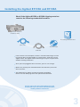
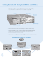
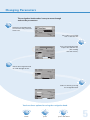
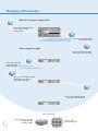
Getting Started
with the
Agilent Pulse Generator
81133A/81134A
You only need a few minutes to get started with
the Agilent 81133A and 81134A Pulse Generator.
i o n,
rmat
,
info ing Guide
ing
m
mm gram
gra Pro .
pro the t CD
te nd oduc
a pr
he
Fo r m
please ore ex
refe amp
r to
l
t h e es a n
del Use d re
iv e r G m
red u o
on ide
t
This Getting Started Brochure helps you to quickly
understand the operating principles and
set up your first signals.
If you need more detailed information on the
Agilent 81133A and 81134A Pulse Generator,
check out the Online Help.
Notice
Safety Summary
Copyright
General Safety Precautions
The following general safety precautions must be
observed during all phases of operation of this
instrument. Failure to comply with these precautions
or with specific warnings elsewhere in this manual
violates safety standards of design, manufacture,
and intended use of the instrument.
© Agilent Technologies, Inc. 2002.
Revision
Revision 1.0, August 2002
Printed in Germany
Agilent Technologies, Deutschland GmbH
Herrenberger Str. 130
71034 Boeblingen, Germany
Agilent Technologies Inc. assumes no liability for
the customer's failure to comply with these
requirements.
Before operation, review the instrument and manual
for safety markings and instructions. You must
follow these to ensure safe operation and to
maintain the instrument in safe condition.
Technology Licenses
General
The hardware and/or software described in this
document are furnished under a license and may
be used or copied only in accordance with the
terms of such license.
This product is a Safety Class 1 instrument
(provided with a protective earth terminal).
The protective features of this product may be
impaired if it is used in a manner not specified in
the operation instructions.
All Light Emitting Diodes (LEDs) used in this
product are Class 1 LEDs as per IEC 60825-1.
Environmental Conditions
Warranty
This instrument is intended for indoor use in an
installation category II, pollution degree
2 environment. It is designed to operate at a
maximum relative humidity of 95% and at altitudes
of up to 2000 meters.
The material contained in this document is provided
“as is,” and is subject to being changed, without
notice, in future editions. Further, to the maximum
extent permitted by applicable law, Agilent disclaims
all warranties, either express or implied, with regard
to this manual and any information contained herein,
including but not limited to the implied warranties of
merchantability and fitness for a particular purpose.
Agilent shall not be liable for errors or for incidental
or consequential damages in connection with the
furnishing, use or performance of this document or of
any information contained herein. Should Agilent and
the user have a separate written agreement with
warranty terms covering the material in this document
that conflict with these terms, the warranty terms in
the separate agreement shall control.
Refer to the specifications tables for the ac mains
voltage requirements and ambient operating
temperature range.
Before Applying Power
Verify that all safety precautions are taken.
The power cable inlet of the instrument
serves as a device to disconnect from
the mains in case of hazard.
The instrument must be positioned so that
the operator can easily access the power
cable inlet. When the instrument is rackmounted the rack must be provided with
an easily accessible mains switch.
Restricted Rights Legend
If software is for use in the performance of a
U.S. Government prime contract or subcontract,
Software is delivered and licensed as “Commercial
computer software” as defined in DFAR 252.227-7014
(June 1995), or as a “commercial item” as defined
in FAR 2.101(a) or as “Restricted computer software”
as defined in FAR 52.227-19 (June 1987) or any
equivalent agency regulation or contract clause. Use,
duplication or disclosure of Software is subject to
Agilent Technologies’ standard commercial license
terms, and non-DOD Departments and Agencies of
the U.S. Government will receive no greater than
Restricted Rights as defined in FAR 52.227-19(c)(1-2)
(June 1987). U.S. Government users will receive no
greater than Limited Rights as defined in FAR 52.227-14
(June 1987) or DFAR 252.227-7015 (b)(2) (November
1995), as applicable in any technical data.
Services and Support
Any adjustment, maintenance, or repair of this
product must be performed by qualified personnel.
Contact your customer engineer through your local
Agilent Technologies Service Center. You can find
a list of local service representatives on the Web at:
http://www.agilent.com/Service/English/index.html
2
Ground the Instrument
To minimize shock hazard, the instrument chassis
and cover must be connected to an electrical
protective earth ground. The instrument must be
connected to the ac power mains through a
grounded power cable, with the ground wire firmly
connected to an electrical ground (safety ground)
at the power outlet. Any interruption of the
protective (grounding) conductor or disconnection
of the protective earth terminal will cause a
potential shock hazard that could result in
personal injury.
Do Not Operate in an Explosive Atmosphere
Do not operate the instrument in the presence of
flammable gases or fumes.
Do Not Remove the Instrument Cover
Operating personnel must not remove instrument
covers. Component replacement and internal
adjustments must be made only by qualified
personnel.
Instruments that appear damaged or defective
should be made inoperative and secured against
unintended operation until they can be repaired by
qualified service personnel.
Installing the Agilent 81133A and 81134A
Check if the Agilent 81133A or 81134A shipping container
contains the following standard deliverables:
The Agilent Pulse Generator
81133A or 81134A
Agilent
Pulse
Genarat
or
This Getting Started Brochure
power cable
The Product CDs
USB cable
If the contents are incomplete, if there is mechanical damage, or if the
instrument does not work within its specifications, notify the nearest
Agilent office. The Agilent office will arrange for repair or replacement
without awaiting settlement.
Once you have plugged in the instrument, you can start using it.
Make sure you keep the ventilation holes free wherever you install
the instrument.
The USB interface will be supported starting spring 2003.
Please visit our Web page for a free update of the firmware.
Please refer to the User Guide delivered on the
Product CD if you need more information about
working with the instrument.
3
Getting Started with the Agilent 81133A and 81134A
Now that you have unpacked the instrument and plugged it in,
let´s take a look at the main elements of the front panel.
Softkeys
Numeric Keys
Global inputs
and outputs
Navigation knob
Channel-specific
inputs and outputs
Tab Keys to navigate
between the pages
Switch on the instrument. You can immediately start playing with the settings.
Start by pressing the tab keys. You see that only the lower part of the panel page
changes. You can switch between five panel pages, which allow you to set
parameters for different instrument settings.
The parameters at the upper part of the panel page are valid for the whole instrument.
Navigate through the pages with the Tab Keys
Main Page
Channel Page
4
Config Page
Data Page
Aux Page
Changing Parameters
The navigation knob makes it easy to move through
and set the parameters.
Rotate the navigation knob
to move from one parameter
to the next.
Let’s select a parameter
from a selection list.
Press the navigation knob
to open the selection list
(like clicking
with the mouse).
Rotate the navigation knob
to scroll through the list.
Select an item by pressing
the navigation knob.
You have three options for using the navigation knob.
rotate
press
press and rotate
5
Changing Parameters
Now let´s change a number field
Press the navigation knob
once to focus at the
number field.
When you rotate the navigation knob
the value changes. You can do this in run time.
It let’s you immediately see the changes on a scope.
Turn the navigation knob
to set the number
Or, to change one digit
Press the navigation knob
once when you are done.
Press and rotate the
navigation knob to
select the digit. You can also press the
arrows next to the navigation knob.
Release the navigation knob.
Now when you rotate it,
the number changes.
Press the navigation knob
once when you are done.
You can also:
6
Use the arrows next the
navigation knob
to select a digit.
Enter a value
with the key pad.
Setting Up a Data Pattern
Imagine, you have designed a new digital circuit with ECL logic and
3.3 GHz clock, and you want to check its correct behavior.
To test it, you decide to simulate a 32-bit pattern signal with NRZ
data output format:
11110011100110010010100100000000
Protect the DUT
Whenever you change a parameter, the generated signal immediately changes.
To protect your DUT, make sure you disconnect the channel outputs first.
Do this by pressing the softkey next the following function:
The open contactor shows you
that your DUT is now disconnected
Now let’s set the instrument parameters
These define the signal that will be generated.
4
Select the Unit
3
Enter the Frequency value
using the keypad
1
2
First, disconnect the outputs
to protect the DUT
Choose the Pulse/Pattern Mode
for the Signal
7
Setting Up a Data Pattern
You can now set the channel mode, timing and
level parameters for the channel
3
Indicates that the Parameters
are set for Channel 1
4
Select the ECL level format
The LEDs show the status
of the outputs
gray = disabled, green = enabled,
crossed out = all outputs disconnected
5
Select Pulse Type NRZ
Enable the Channel 1 normal Output
by pressing the respective softkey
2
-
Select Pulse Mode Data
You can switch
between the two channels
by pressing this softkey
1
Switch to the Channel Page
Now let’s set the data
3
Enter a data pattern
length of 32 bits
4
2
Enter your data pattern
Switch to the Numeric Edit Mode
1
Switch to the Data Page
8
Setting Up a Data Pattern
Reconnect the DUT
When you are done, you can reconnect the DUT by clicking the following softkey:
If you attach a scope (as DUT), you can immediately see the signal
You can use the generator’s trigger output to trigger the scope.
The LEDs tell you which
outputs are enabled
2
Enable the Trigger Output ...
... or press the
Trigger Out softkey
1
Switch to Aux Page
Now you can view the data pattern and the trigger output signal
on your oscilloscope
9
What Else You Can Do
The Agilent 81133A and 81134A Pulse/Pattern Generators are high-end,
easy-to-use tools for generating pulses, patterns and data at speeds
up to 3.35 MHz. They are ideal instruments for testing logic devices
(for example, ECL, LVPECL, LVDS) and other digital devices with
clock rates from 15 MHz to 3.35 GHz.
You can use the Pulse/Pattern Generators for applications where timing and
performance are critical and full control over signal jitter is required.
The instruments are ideal data and pattern sources for eye diagram
measurements.
Your advantages are
Fast rise times, low jitter
and full parameter flexibility
When timing is critical, the 81133/34A’s
fast rise times, the low jitter and full parameter
flexibility make it an ideal pulse,
clock and data source.
PRBS from 25-1 to 231-1
You can evaluate the performance of a device
in eye diagram measurements with PRBS
from 25-1 to 231-1.
Full signal manipulation
You can add jitter to clock or data signals
with the Delay Control Input and deform the
eye with the Variable Crossover Point.
Predefined Levels
You can use the predefined levels
to easily set up channels for commonly
used logic families. These are:
ECL, LVPECL, LVDS.
Data can be 8 kB of pattern memory
You can create large data patterns
with 8 kB of pattern memory.
Agilent Email Updates
http://www.agilent.com/find/emailupdates
Get Free Email Updates
Keep up to date with Agilent’s free Email Updates. As a subscriber, you will recieve regular, cusomized email updates on the
topics you select. Updates cover support, products and services, applications, promotions, events, and other areas.
It is easy to unsubscribe or change your prferences. Subscribe today:
http://www.agilent.com/find/emailupdates
10
Agilent is committed to respecting and protecting your privacy. Our Privacy Statement at
http://www.agilent.com/go/privacy
describes our commitment to you. Please direct any questions
about Agilent’s privacy program to
[email protected]
Requirements and Possibilities for Remote Control
Using the Pulse Generator's Remote Control Interfaces
You can integrate the Pulse Generator in your production environment.
Its remote programming interfaces (USB, LAN, GPIB) allow you to set up
extensive tests that involve several instruments.
The accompanying Agilent I/O Libraries for instrument control must be
installed on the controlling PC.
It is possible that your Generator’s firmware is not set up for USB.
USB functionality will be included in a later release of the firmware.
Check the Agilent Web page for update information.
For detailed information on how to connect the instrument
physically to your external PC, and what you have to do to talk
to the instrument, please refer to the Programming Guide
delivered on the Product CD.
11
Agilent Corporate Information, Product Numbers
For more information, please visit us at:
www.agilent.com/find/pulse_generator
Ordering Information
Agilent 81133A
Agilent 81134A
3.35 GHz 1-channel Pulse/Pattern Generator
3.35 GHz 2-channel Pulse/Pattern Generator
Options
Agilent 8113xA-UK6
Agilent 8113xA-1CP
Agilent 1494-0059
Commerical Calibration Certificate with Test Data
Rackmount and Handle kit
Rack Slide Kit
Accessories
Agilent 15435 A
Agilent 15432 B
Agilent 15433 B
Agilent 15434 B
Agilent 15438 A
Transition Time Converter 150ps
Transition Time Converter 250ps
Transition Time Converter 500ps
Transition Time Converter 1000ps
Transition Time Converter 2000ps
Warranty and service
3 years Return-to-Agilent (Standard with every Order)
5 years Return-to-Agilent
Commercial Calibration for 3 years
Commercial Calibration for 5 years
Standard Compliant Calibration for 3 years
Standard Compliant Calibration for 5 years
Related Agilent Literature
Agilent Family of Pulse/Pattern
Generators Brochure
P/N 5980-0489E
Agilent 81100 Family Pulse/Pattern
Produkt Overview P/N 5980-1215E
Agilent 3.35 GHz Pulse/Pattern
Generators Photocard P/N 5988-5935EN
Agilent Technologies 81133A
and 81134A 3.35 GHz Pulse/Pattern
Generators, Technical Specifications
P/N 5988-5549EN
12
Need to test jitter?
P/N 5988-7050EN
81133-91010