1
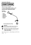
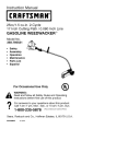
Operator's
Manual
CRFIFTSMFIN
24cc/1.3 cu.in. 2-Cycle
17 Inch Cutting Path / .080 In. Line
GASOLINE
WEEDWAOKER
®
Model No.
358.798210
WARNING:
Read and follow all Safety Rules and Operating
Instructions
before first use of this product.
For answers
Call 7 am-7
to your questions about this product:
pm, Mon.-Sat.,
or 10 am-7 pm, Sun.
1-800-235-5878
Sears,
530087368
Roebuck
03/10/99
and Co., Hoffman
_Hoors listed are Central Time)
Estates,
IL 60179 USA
Warranty Statement
Safety Rules
Assembly
Operation
Maintenance
Service & Adjustments
2
2
4
5
9
10
Storage
Troubleshooting
Chart
Emissions Statement
Parts List
Spanish
Parts and Ordering
FULL ONE YEAR WARRANTY ON CRAFTSMAN
WEEDWAOKER _; LINE TRIMMER.
11
12
12
14
17
Back
:_ GAS POWERED
For one year from the date of purchase, when this Craftsman Gas Powered
Weedwacker
Line Trimmer is maintained, lubricated, and tuned up according to
the operating and maintenance instructions in the Operator's Manual, Sears will
repair, free of charge, any defect in materials or workmanship.
This warranty excludes nylon line, spark plug, and air filter, which are expendable
parts and become worn during normal use.
If this Weedwacker line trimmer is used for commercial purposes, this warranty applies for only 90 days from the date of purchase. If this Weedwacker line trimmer is
used for rental purposes, this warranty applies for only 30 days from the date of purchase. This warranty applies only while this product is in use in the United States.
WARRANTY SERVICE IS AVAILABLE BY RETURNING THE WEEDWACKER LINE TRIMMER TO THE NEAREST SEARS SERVICE CENTER IN THE UNITED STATES.
This warranty gives you specific legal rights, and you may also have other rights
which vary from state to state.
Sears, Roebuck and Co., D/817 WA Hoffman Estates, IL 60179
G-OG
WARNING:
When using gardening
appliances, basic safety precautions
must always be followed to reduce the
risk of fire and serious injury. Read and
follow all instructions.
wARNING:
Eye Protection
/
Safety information
on the unit __
DANGER: Never use blades
devices. This unit is designed
trimmer use only. Use of any
cessories or attachments will
the risk of injury.
Trimmer line throws ob-
jects violently. You and others can be
blinded/injured. Wear eye and leg
protection. Keep body parts clear of rotating line. Keep children, bystanders,
and animals 50 feet (15 meters) away. If
approached stop unit immediately.
This power unit can be dangerous I. Operator is responsible for following instructions and warnings on unit and in
manual. Read entire Operator's Manual
before using unit! Be thoroughly familiar
with the controls and the proper use of
the unit. Restrict the use of this unit to
persons who have read, understand,
and will follow the instructions and warnings on the unit and in the manual. Never allow children to operate this unit.
HazardZone
E oots
If situations occur which are not
covered in this manual, use care and
good judgement. If you need
assistance, contact your Authorized
Service Dealer or call 1-800-235-5878.
or flailing
for line
other acincrease
2
OPERATOR
SAFETY
• Move at least 10 feet (3 meters)
• Always
wear
safety
eyeprotection. away from fueling site before starting
• Always
wear
longpants,
long
engine.
sleeves,
boots,
andgloves.
Wearing • Stop engine and allow to cool before
safety
legguards
isrecommended. removing fuel cap.
Donotgobarefoot
orwearsandals. CUTTING SAFETY
Stayclear
ofspinning
line.
only for trimming, scalping, mow• Secure
hairabove
shoulder
length. • Use
ing, edging, and sweeping. Do not use
Secure
orremove
loose
clothing
or
for pruning or hedge trimming.
clothing
withloosely
hanging
ties,
• Inspect the area before each use.
straps,
tassels,
etc.Theycanbe
Remove objects (rocks, broken
caught
inmoving
parts.
Being
fully
glass, nails, wire, etc.) which can be
covered
alsohelps
protect
youfrom thrown by or become entangled in
debris
andpieces
oftoxicplants
line. Hard objects can damage the
thrown
byspinning
line.
trimmer head and be thrown causing
• Donotoperate
whenyouaretired,
serious injury.
ill,upset,
orunder
theinfluence
of
• Keep firm footing and balance. Do
alcohol,
drugs,
ormedication.
not overreach.
• Wear
hearing
protection
ifyouuse
• Keep all parts of your body away
unitformore
than1-1/2
hours
per
from muffler and spinning line. Keep
day.
engine below waist level. A hot muf• Never
startorruninside
aclosed
fler can cause serious burns.
room
orbuilding.
Breathing
exhaust • Cutting on left side of the shield will
fumes
cankill.
throw debris away from the operator.
• Keep
handles
freefromoilandfuel. TRANSPORTING
AND STORAGE
UNIT / MAINTENANCE
SAFETY
• Disconnect the spark plug before
performing maintenance except carburetor adjustments.
• Look for and replace damaged or
loose parts before each use. Look
for and repair fuel leaks before use.
Keep in good working condition.
• Replace trimmer head parts that are
chipped, cracked, broken, or damaged in any other way before using
the unit.
• Make sure unit is assembled correctly as shown in this manual.
• Make carburetor adjustments with
lower end supported to prevent line
from contacting any object.
• Keep others away when making carburetor adjustments.
• Use only recommended
Craftsman
accessories and replacement parts.
FUEL
•
•
•
•
SAFETY
Mix and pour fuel outdoors.
Keep away from sparks or flames.
Use a container approved for fuel.
Do not smoke or allow smoking near
fuel or the unit.
• Wipe up all fuel spills.
• Allow engine to cool; secure unit before storing or transporting in vehicle.
• Empty the fuel tank before storing or
transporting the unit. Use up fuel left
in the carburetor by starting the engine and letting it run until it stops.
• Store unit and fuel in area where fuel
vapors cannot reach sparks or open
flames from water heaters, electric
motors or switches, furnaces, etc.
• Store unit so line limiter cannot accidentally cause injury. The unit can be
hung by the tube.
• Store unit out of reach of children.
If situations occur which are not covered in this manual, use care and
good judgment. If you need assistance, call 1-800-235-5878.
SPECIAL
NOTICE:
This unit is not
equipped with a temperature limiting
muffler and spark arresting screen
which meets the requirements of California Codes 4442 and 4443. All U.S.
forest land and the states of California,
Idaho, Maine, Minnesota, New Jersey,
Oregon, and Washington require by
law that many internal combustion engines be equipped with a spark arres-
torscreen.
Ifyouoperate
inalocale
where
suchregulations
exist,
youare
legally
responsible
forinstalling
and
maintaining
theoperating
condition
of
these
parts.
Failure
todosoisaviolationoflaw.Contact
aSears
Service
Center
forthecorrect
parts.
SPECIAL
NOTICE:
Exposure
to
vibrations
through
prolonged
useof
gasoline
powered
handtoolscould
cause
blood
vessel
ornerve
damage
inthefingers,
hands,
andjoints
of
people
prone
tocirculation
disorders
or
abnormal
swellings.
Prolonged
usein
coldweather
hasbeenlinked
toblood
vessel
damage
inotherwise
healthy
people.
Ifsymptoms
occur
suchas
numbness,
pain,
lossofstrength,
change
inskincolorortexture,
orloss
offeeling
inthefingers,
hands,
or
joints,
discontinue
theuseofthistool
andseekmedical
attention.
Anantivibration
system
doesnotguarantee
theavoidance
ofthese
problems.
Userswhooperate
power
toolsonacontinualandregular
basis
mustmonitor
closely
theirphysical
condition
andthe
condition
ofthistool.
CARTON
CONTENTS
Check
carton
contents
against
thefollowing
list.
• Rotate the handle on the tube to an
Model 358.798210
• Trimmer
• Shield
• Wing Nut (screwed
• Container of Oil
onto shield)
Examine parts for damage. Do not use
damaged parts.
NOTE: If you need assistance or find
parts missing or damaged, call
1-800-235-5878.
It is normal for the fuel filter to rattle in
the empty fuel tank.
Finding fuel or oil residue on muffler is
normal due to carburetor adjustments
and testing done by the manufacturer.
ASSEMBLY
WARNING:If
received assembled,
repeat all steps to ensure your unit is
properly assembled and all fasteners
are secure.
ADJUSTING
THE HANDLE
WARNING:When
adjusting the handle, be sure it remains between the
trigger and the safety label.
• Loosen wing nut or knob on handle.
upright position; retighten
ATTACHING
wing nut.
SHIELD
WARNING:The
shield must be properly installed. The shield provides partial
protection from the risk of thrown objects
to the operator and others and is
equipped with a line limiter which cuts
excess line to the proper length. The line
limiter (on underside of shield) is sharp
and can cut you. For proper orientation,
see illustration in Operation section.
• Remove wing nut from shield.
• Insert bracket into slot as shown.
• Pivot shield until bolt passes through
hole in bracket.
• Securely tighten wing nut onto bolt.
Slot
Shield
,J
Bracket
Wing
Nut
KNOW
YOUR
TRIMMER
READ THIS OPERATOR'S MANUAL AND SAFETY RULES BEFORE OPERATING YOUR
UNIT. Compare the illustrations with your unit to familiarize yourself with the location of the various controls and adjustments. Save this manual for future reference.
Assist Handle
Tube
J
"\ Throttle
ON/STOP
Trigger
Switch \
Muffler
Trimmer
Head
Spark Plug
Starter
Shield
Choke Lever
Primer Bulb
Fuel Mix
Fill Cap
ON/STOP SWITCH
The STOP switch is used to stop engine.
Press and hold switch to stop engine.
PRIMER BULB
The primer bulb removes air from the
fuel lines and fills them with fuel. This
allowing it to return to its original form.
CHOKE
The choke helps to supply fuel to the
carburetor during starting. This allows
you to start a cold engine. Activate the
choke by moving choke lever to the Full
position. After the engine has started,
move the choke to the Off position.
allows you to start the engine with fewer pulls on the starter rope. Activate
the primer bulb by pressing it and
BEFORE
STARTING
ENGINE
WARNING:Be
sure to read the fuel
Once oil is added to gasoline, shake
container momentarily to assure that
the fuel is thoroughly mixed. Always
read and follow the safety rules
relating to fuel before fueling your unit.
information in the safety rules before
you begin. If you do not understand
the safety rules, do not attempt to fuel
your unit. Call 1-800-235-5878.
FUELING
Line
Limiter
Blade
IMPORTANT
ENGINE
Experience indicates that alcohol
blended fuels (called gasohol or using
ethanol or methanol) can attract moisture which leads to separation and
formation of acids during storage.
Acidic gas can damage the fuel system of an engine while in storage.
To avoid engine problems, empty the
fuel system before storage for 30 days
or longer. Drain the gas tank, start the
engine and let it run until the fuel lines
and carburetor are empty. Use fresh
fuel next season.
This engine is certified to operate on
unleaded gasoline. Before operation,
gasoline must be mixed with a good
quality 2-cycle air-cooled engine oil.
We recommend Craftsman brand oil.
Mix gasoline and oil at a ratio of 40:1
(A 40:1 ratio is obtained by mixing 3.2
ounces of oil with 1 gallon of unleaded
gasoline). DO NOT USE automotive oil
or boat oil. These oils will cause
engine damage. When mixing fuel,
follow instructions printed on container.
5
Never
useengine
orcarburetor
cleanerproducts
inthefueltankorpermanentdamage
mayoccur.
SeetheSTORAGE
section
foradditional
information.
STOPPING
YOURENGINE
• Press
andholdtheOn/Stop
switch
in
theSTOP
position.
• Ifengine
doesnotstop,move
choke
lever
tofullposition.
Lever
Engine Choke
Stop
Switch
",
STARTING
YOUR ENGINE
COLD ENGINE OR WARM ENGINE
AFTER RUNNING OUT OF FUEL
WARNING:The
trimmer head will
turn while starting the engine.
Avoid any contact with the muffler. A
hot muffler can cause serious burns.
• Rest engine and shield on ground,
supporting trimmer head off ground.
• Move the choke lever to the Full
Choke position.
• Slowly press the primer bulb 6 times.
• Squeeze and hold the throttle trigger.
Keep throttle trigger fully squeezed
until the engine runs smoothly.
:; ;,Ohoke
Lever
U_ r
• Pull starter rope sharply 5 times.
NOTE: If the engine sounds as if it is
trying to start before the 5th pull, go to
the next step.
• Move the choke lever to the Half
Choke position.
• Pull starter rope sharply until engine
runs, but no more than 6 pulls.
NOTE: If the engine has not started
after 6 pulls (at half choke), check to
make sure the choke lever is in the
proper position. Then, move the choke
lever to the Full Choke position and
press the primer bulb 6 times; squeeze
and hold the throttle trigger and pull
the starter rope 2 more times. Move
the choke lever to Half Choke and pull
the starter rope until the engine runs,
but no more than 6 more pulls. If the
engine still has not started, it is probably flooded. Proceed to "Starting a
Flooded Engine."
• Allow the engine to run 10 seconds,
then move the choke lever to Off
Choke. Allow the unit to run for 30
more seconds at Off Choke before
releasing the throttle trigger.
NOTE: If engine dies with the choke
lever at the Off Choke position, move
the choke lever to Half Choke and pull
the rope until engine runs.
STARTING
A WARM
ENGINE
• Move the choke lever to the Half
Choke position.
• Squeeze and hold the throttle trigger.
Keep throttle trigger fully squeezed
until the engine runs smoothly.
• Pull starter rope sharply until engine
runs, but no more than 5 pulls.
• Allow engine to run 15 seconds, then
move the choke lever to Off Choke.
NOTE: If engine has not started, pull
starter rope 5 more pulls. If engine still
does not run, it is probably flooded.
DIFFICULT
STARTING
STARTING
A FLOODED
OR
ENGINE
Flooded engines can be started by
placing the choke lever in the Off
Choke position; then, pull the rope to
clear the engine of excess fuel. This
could require pulling the starter handle
many times depending on how badly
the unit is flooded.
If the unit still doesn't start, refer to
TROUBLESHOOTING
chart or call
1-800-235-5878.
OPERATING INSTRUCTIONS
OPERATING POSITION
ALWAYS WEAR:
_
j_
H_°;gY _t_s
Cut from
_.
Llrnplei_e rg_hU.t
s line t° "_
_
Eye Protection
__
your
right to your
left.
Bring the engine to cutting speed before entering the material to be cut.
Do not run the engine at a higher
speed than necessary. The cutting line
will cut efficiently when the engine is
run at less than full throttle. At lower
speeds, there is less engine noise and
vibration. The cutting line will last
longer and will be less likely to "weld"
onto the spool.
If the trimmer head does not turn when
the engine is in operation, make sure
the drive shaft housing is properly
seated in engine shroud.
Always release the throttle trigger and
allow the engine to return to idle speed
when not cutting.
To stop engine:
• Release the throttle trigger.
• Push and hold down the on/stop
switch until the engine has stopped
completely.
TRIMMER
LINE
To advance line, tap bottom of trimmer
head on ground one time.
ADVANCE
The trimmer line will advance approximately 2 in. (5 cm) each time the bottom of the trimmer head is tapped on
the ground with the engine running at
full throttle.
Always tap the trimmer head on a
grassy area. Tapping on surfaces such
as concrete or asphalt can cause excessive wear to the trimmer head.
Ifthe line is worn down to 2 in. (5 cm)
or less, more than one tap will be required to obtain the most efficient line
length.
WARNING;Use
only .080" (2 mm)
diameter line. Other sizes of line will
not advance properly and can cause
serious injury. Do not use other materials such as wire, string, rope, etc. Wire
can break off during cutting and become a dangerous missile that can
cause serious injury.
CUTTING
METHODS
WARNING:Use
minimum speed and
do not crowd the line when cutting
around hard objects (rock, gravel,
fence posts, etc.), which can damage
the trimmer head, become entangled
in the line, or be thrown causing a serious hazard.
• The tip of the line does the cutting.
You will achieve the best performance and minimum line wear by not
crowding the line into the cutting
area. The right and wrong ways are
shown below.
Tip of the Line
Does The Cutting
Line Crowded Into
Work Area
The most efficient line length is the
maximum length allowed by the line
limiter.
Always keep the shield in place when
the tool is being operated.
To Advance Line:
• Operate the engine at full throttle.
• Hold the trimmer head parallel to and
above the grassy area.
• Tap the bottom of the trimmer head
lightly on the ground one time. Approximately 2 in. (5 cm) of line will be
advanced with each tap.
Right_'
Wrong
" _'=.
• The line will easily remove grass and
weeds from around walls, fences,
trees and flower beds, but it also can
cut the tender bark of trees or shrubs
and scar fences. To help avoid damage especially to delicate vegetation
or trees with tender bark, shorten line
to 4-5 in. (10-13 cm) and use at less
than full throttle.
MOWING - Your trimmer is ideal for
• Fortrimming
orscalping
useless
thanfullthrottle
toincrease
linelife
mowing in places conventional lawn
anddecrease
headwearespecially:mowers cannot reach. In the mowing
• During
lightdutycutting
position, keep the line parallel to the
• Near
objects
around
which
theline ground. Avoid pressing the head into
the ground as this can scalp the
canwrapsuchassmallposts
treesorfence
wire
ground and damage the tool.
• Formowing
orsweeping
usefull
Mowing
I_
throttle
foragoodclean
job
WARNING:Always
weareyeprotec_
44
tion.Never
leanoverthetrimmer
head.
.___. -;_
Rocks
ordebris
canricochet
orbe
thrown
intoeyesandfaceandcause
÷_,;_ :_' _
blindness
orother
serious
injury.
TRIMMING
- Hold
thebottom
ofthe
SWEEPING - The fanning action of
trimmer
head
about
3in.(8cm)above the rotating line can be used for a
theground
andatanangle.
Allowonly quick and easy clean up Keep the line
thetipofthelinetomake
contact.
Do parallel to and above the surfaces be
notforcetrimmer
lineintoworkarea. ing swept and move the tool from side
Trimming
. • _.
to side
Sweeping
3in.
Above Ground
y
_" _ _'__,
SCALPING - The scalping technique
removes unwanted vegetation. Hold
the bottom of the trimmer head about 3
Scalping
- Your unit can be used for
edging sidewalks, patios, driveways, etc.
While edging, allow the tip of the line to
make contact. Do not force line. Take
extra caution while edging as objects
can be thrown by trimmer line.
...........
in. (8 cm) above the ground and at an
angle. Allow the tip of the line to strike
the ground around trees, posts, monuments, etc. This technique increases
line wear.
EDGING
/
MAINTENANCESCHEDULE
CARE & MAINTENANCE
Check for Loose fasteners
TASK
WHEN TO PERFORM
and parts
Before each use
Check for damaged or worn parts
Clean unit and labels
Before each use
After each use
Clean air filter
Every 5 hours of operation
Replace
Yearly
GENERAL
spark plug
RECOMMENDATIONS
CLEAN
AIR
FILTER
The warranty on this unit does not cover items that have been subjected to
operator abuse or negligence. To receive full value from the warranty, the
operator must maintain unit as instructed in this manual. Various adjustments
will need to be made periodically to
properly maintain your unit.
CHECK
FOR LOOSE
FASTENERS
AND PARTS
• Spark Plug Boot
• Air Filter
Do not clean filter in gasoline or other
flammable solvent to avoid creating a
fire hazard or producing harmful evaporative emissions.
A dirty air filter decreases engine performance and increases fuel consumption and harmful emissions. Always
clean after every 5 hours of operation.
• Clean the cover and the area around
it to keep dirt from falling into the
carburetor chamber when the cover
is removed.
• Housing Screws
• Assist Handle Screws
• Debris Shield
•
•
•
•
CHECK
FOR DAMAGED
OR
WORN
PARTS
Refer replacement of damaged/worn
parts to your Sears Service Center.
• On/Stop Switch - Ensure On/Stop
switch functions properly by pressing
and holding the switch in the "Stop"
position. Make sure engine stops;
then restart engine and continue.
• Fuel Tank - Discontinue use of unit if
fuel tank shows signs of damage or
leaks.
• Debris Shield - Discontinue use of
unit if debris shield is damaged.
CLEAN
UNIT & LABELS
• Clean the unit using a damp cloth
with a mild detergent.
• Wipe off unit with a clean dry cloth.
Remove parts as illustrated.
Wash the filter in soap and water.
Allow filter to dry.
Add a few drops of oil to the filter;
squeeze the filter to distribute oil.
• Replace parts.
_
_'_
Air Filter
Cover
Air Filter
._-_
Screws
-"
"_
REPLACE
SPARK
PLUG
Replace the spark plug each year to
ensure the engine starts easier and
runs better. Set spark plug gap at
.025 in. Ignition timing is fixed and
nonadjustable.
• Twist, then pull off spark plug boot.
• Remove spark plug from cylinder
and discard.
• Replace with Champion CJ-8Y spark
plug and tighten with a 3/4 in. socket
wrench (10-12 ft.-Ibs).
• Reinstall the spark plug boot.
REPLACING
THE LINE
• Push and hold the engine stop switch
in the stop/off position until the unit has
fully stopped.
• Disconnect the spark plug lead wire.
• Remove the spool by firmly pulling on
the tap button.
• Clean entire surface of hub and spool.
• Replace with a pre-wound spool, or
cut two 12.5 foot (3.8 m) lengths of
.080" (2 mm) diameter
Craftsman
brand line. Never use wire, rope,
string, etc., which can break off and
become a dangerous missile.
• Insert ends of line about 1/2 inch (1 cm)
into the small holes inside spool.
Spool
/_
.............
_-//
Small
Holes
• Wind the line evenly and tightly onto
the spool. Wind in the direction of the
arrows found on the spool.
• Push the line into the notches, leaving
3 to 5 inches (7 - 12 cm) unwound.
• Insert the line into the the exit holes in
the hub as shown in the illustration.
Line exit holes
Line in Notch
damage the engine as well as the carburetor. If you require further assistance or are unsure about performing
this procedure, call our customer assistance help line at 1-800-235-5878.
Old fuel, a dirty air filter, a dirty fuel filter, or flooding may give the impression of an improperly adjusted carburetor. Check these conditions before
adjusting the carburetor.
The carburetor has been carefully set
at the factory. Adjustments may be
necessary if you notice any of the following conditions:
• Engine will not idle. See "Idle Speed"
under adjusting procedure.
• Engine dies or hesitates instead of
accelerating. See "Acceleration
Check" under adjusting procedure.
• Loss of cutting power. See "Mixture
Adjustment" under adjusting
procedure.
There are two adjustment screws on
the carburetor.
Screw
Mixture Screw.
(with Limiter
Cap)
\
\\\\
/
\'i
"I
Hub
J
Line in Notch
• Align notches with the line exit hole.
• Push the spool into the hub until it
snaps into place.
• Pull the line extending outside of the
hub to release it from the notch.
CARBURETOR
ADJUSTMENT
WARNING:The
trimmer head will be
spinning during most of this procedure.
Wear your protective equipment and
observe all safety precautions. After
making mixture adjustments, recheck
idle speed.
Carburetor adjustment is critical and if
done improperly can permanently
Air Filter
"_
Cover
CARBURETOR
PRESETS
When making carburetor preset adjustments, do not force plastic limiter caps
beyond stops or damage will occur.
If carburetor presets are not needed,
proceed to "Adjusting Procedure, Idle
Speed."
To adjust presets:
• Turn mixture screw counterclockwise
until it stops.
• Turn the idle speed screw clockwise
until it stops. Now turn counterclockwise 4-1/2 turns.
• Start motor, cut grass for 3 minutes,
and proceed to the adjustment
section. If engine does not start,
refer to troubleshooting
chart or call
1-800-235-5878.
• If engine performance is acceptable
at the preset positions, no further
adjustment is necessary.
10
ADJUSTING
PROCEDURE
Idle Speed
Allow engine to idle. Adjust speed until
engine runs without stalling.
• Turn clockwise to increase engine
speed if engine stalls or dies.
• Turn counterclockwise
to decrease
speed.
No further adjustments are necessary
if performance is satisfactory.
Mixture Adjustment "H"
DO NOT operate engine at full throttle
for prolonged periods while making adjustments. Damage to the engine can
occur. Extend line to the length allow
by the line limiter and cut some grass.
Based on performance while cutting,
turn the mixture adjustment in
1/16-turn increments as follows:
Prepare unit for storage at end of season or if it will not be used for 30 days
or more.
WARNING:
• Allow engine to cool, and secure the
unit before storing or transporting.
• Store unit and fuel in a well ventilated area where fuel vapors cannot
reach sparks or open flames from
water heaters, electric motors or
switches, furnaces, etc.
• Store unit with all guards in place.
Position unit so that any sharp object
cannot accidentally cause injury.
• Store unit and fuel well out of the
reach of children.
EXTERNAL
SURFACES
If your unit is to be stored for a period
of time, clean it thoroughly before storage. Store in a clean dry area.
• Lightly oil external metal surfaces.
FUEL
SYSTEM
Under Fueling Engine in the Operating
Section of this manual, see message
labeled IMPORTANT regarding the use
of gasohol in your engine.
Fuel stabilizer is an acceptable alternative in minimizing the formation of
fuel gum deposits during storage. Add
• Clockwise until the engine has good
power while cutting with no hesitation.
Do not adjust by sound or speed, but
judge by how well the engine performs while cutting.
• Counterclockwise
if the engine has
speed but dies or lacks power while
cutting.
After completing adjustments, check
for acceleration. Reset if necessary.
Acceleration
Check
If engine dies or hesitates instead of
accelerating, turn mixture adjustment
counterclockwise
until you have
smooth acceleration. Recheck and adjust as necessary
formance.
for acceptable
per-
stabilizer to the gasoline in the fuel
tank or fuel storage container. Follow
the mix instructions found on stabilizer
container. Run engine at least 5 minutes after adding stabilizer.
CRAFTSMAN 40:1,2-cycle
engine oil
(air cooled) is already blended with
fuel stabilizer. If you do not use this
Sears oil, you can add a fuel stabilizer
to your fuel tank.
INTERNAL
ENGINE
• Remove spark plug and pour 1 teaspoon of 40:1,2-cycle
engine oil (air
cooled) through the spark plug opening. Slowly pull the starter rope 8 to
10 times to distribute oil.
• Replace spark plug with new one of
recommended type and heat range.
• Clean air filter.
• Check entire unit for loose screws,
nuts, and bolts. Replace any damaged, broken, or worn parts.
• At the beginning of the next season,
use only fresh fuel having the proper
gasoline to oil ratio.
OTHER
• Do not store gasoline from one season to another.
• Replace your gasoline can if it starts
to rust.
11
TROUBLESHOOTING
CHART
TROUBLE
CAUSE
REMEDY
Engine will not
start.
•
•
•
•
•
•
•
•
Engine flooded.
Fuel tank empty.
Spark plug not firing.
Fuel not reaching
carburetor.
• Compression
Engine will not
idle properly.
See "Starting Instructions."
Fill tank with correct fuel mixture.
Install new spark plug.
Check for dirty fuel filter; replace.
Check for kinked or split fuel line;
repair or replace.
• Contact a Sears Service Center.
low.
• Idle speed set too low.
• Idle speed set too high.
• Carburetor requires
adjustment.
• Crankshaft seals worn.
• Compression
low.
Engine will not
accelerate,
lacks power,
or dies under
a load.
Engine smokes
excessively.
• Air filter dirty.
• Spark plug fouled.
• Carburetor requires
adjustment.
• Carbon build up.
• Compression
low.
• Choke partially on.
• Fuel mixture incorrect.
• Air filter dirty.
• Carburetor requires
adjustment.
Engine runs hot. • Fuel mixture incorrect.
• Spark plug incorrect.
• Carburetor requires
adjustment
• Carbon build up.
YOUR WARRANTY RIGHTS AND
OBLIGATIONS:
The U. S. Environmental Protection Agency/California
Air Resources Board and SEARS,
ROEBUCK AND CO., USA are
pleased to explain the emissions control system warranty on your lawn and
garden equipment engine. All new utility and lawn and garden equipment
engines must be designed, built, and
equipped to meet the stringent antismog standards. SEARS must warrant
the emission control system on your
lawn and garden equipment engine for
• Adjust idle speed screw
clockwise to increase speed.
• Adjust idle speed screw counterclockwise to reduce speed.
• See "Carburetor Adjustments."
• Contact a Sears Service Center.
• Contact a Sears Service Center.
• Clean or replace air filter.
• Clean or replace spark plug
and re-gap.
• See "Carburetor Adjustments."
• Contact a Sears Service Center.
• Contact a Sears Service Center.
• Move choke to off position.
• Empty fuel tank and refill with
correct fuel mixture.
• Clean or replace air filter.
• See "Carburetor Adjustments."
• See "Fueling Your Unit."
• Replace with correct spark plug.
• See "Carburetor Adjustments."
• Contact a Sears Service Center.
the periods of time listed below provided there has been no abuse, neglect, or improper maintenance of your
lawn and garden equipment engine.
Your emission control system includes
parts such as the carburetor and the
ignition system. Where a warrantable
condition exits, SEARS will repair your
lawn and garden equipment engine at
no cost to you. Expenses covered under warranty include diagnosis, parts
and labor. MANUFACTURER'S
WARRANTY COVERAGE:
If any emissions
related part on your engine (as listed
12
under
Emissions
Control
Warranty RIOD: Any warranted part which is not
Parts
List)isdefective
oradefect
in
scheduled for replacement as required
thematerials
orworkmanship
ofthe
maintenance, or which is scheduled
engine
causes
thefailure
ofsuch
an
only for regular inspection to the effect
emission
related
part,thepartwillbe
of "repair or replace as necessary"
repaired
orreplaced
bySEARS.
shall be warranted for 2 years. Any
OWNER'S
WARRANTY
RESPONSI-warranted part which is scheduled for
BILITIES:
Asthelawnandgarden
replacement as required maintenance
equipment
engine
owner,
youarere- shall be warranted for the period of
sponsible
fortheperformance
ofthe
time up to the first scheduled replacerequired
maintenance
listed
inyour
ment point for that part. DIAGNOSIS:
Owner's
Manual.
SEARS
recommends
The owner shall not be charged for
thatyouretain
allreceipts
covering diagnostic labor which leads to the demaintenance
onyourlawnandgarden termination that a warranted part is deequipment
engine,
butSEARS
cannot fective if the diagnostic work is perdenywarranty
solely
forthelackofre- formed at an approved SEARS
ceipts
orforyourfailure
toensure
the servicing center. CONSEQUENTIAL
performance
ofallscheduled
mainte- DAMAGES: SEARS may be liable for
nance.Asthelawnandgarden
damages to other engine components
equipment
engine
owner,
youshould caused by the failure of a warranted
beaware
thatSEARS
maydeny
you part still under warranty. WHAT IS
NOT COVERED: All failures caused
warranty
coverage
ifyourlawnand
garden
equipment
engine
orapartofit by abuse, neglect, or improper maintenance are not covered. ADD-ON OR
hasfailed
duetoabuse,
neglect,
improper
maintenance,
unapproved MODIFIED PARTS: The use of add-on
modifications,
ortheuseofpartsnot
or modified parts can be grounds for dismade
orapproved
bytheoriginal
allowing a warranty claim. SEARS is not
equipment
manufacturer.
Youarere- liable to cover failures of warranted
sponsible
forpresenting
yourlawnand parts caused by the use of add-on or
garden
equipment
engine
toa SEARS modified parts. HOW TO FILE A
authorized
repair
center
assoon
asa
CLAIM: If you have any questions reproblem
exists.
Warranty
repairs
garding your warranty rights and reshould
becompleted
ina reasonable sponsibilities, you should contact your
amount
oftime,nottoexceed
30days. nearest authorized service center or
Ifyouhave
anyquestions
regarding call SEARS at 1-800-473-7247.
yourwarranty
rights
andresponsibili- WHERE TO GET WARRANTY SERties,youshould
contact
yournearest VICE: Warranty services or repairs shall
authorized
service
center
orcall
be provided at all SEARS service cenSEARS
at1-800-473-7247
WARRAN-ters. call: 1-800-473-7247. MAINTETY COMMENCEMENT
DATE: The
warranty period begins on the date the
lawn and garden equipment engine is
purchased.
LENGTH OF COVERAGE: This warranty shall be for a period of two years from the initial date of
purchase. WHAT IS COVERED: REPAIR OR REPLACEMENT
OF
PARTS. Repair or replacement of any
warranted part will be performed at no
charge to the owner at an approved
SEARS servicing center. If you have
any questions regarding your warranty
rights and responsibilities,
you should
contact your nearest authorized service center or call SEARS at
1-800-473-7247.
WARRANTY PE-
NANCE, REPLACEMENT AND REPAIR OF EMISSION RELATED
PARTS: Any SEARS approved replacement part used in the performance of any warranty maintenance
or repair on emission related parts will
be provided without charge to the owner if the part is under warranty. EMISSION CONTROL WARRANTY
PARTS LIST: Carburetor, Ignition System: Spark Plug (covered up to maintenance schedule), Ignition Module.
MAINTENANCE
STATEMENT: The
owner is responsible for the performance of all required maintenance as
defined in the owner's manual.
13