1
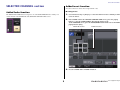
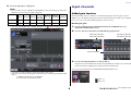
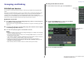
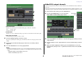
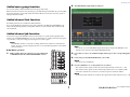
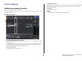
V2.0 Supplementary Manual
This supplementary manual explains mainly the functions that have been added or changed in
CL5/CL3/CL1 firmware V2.0.
Use it in conjunction with the CL5/CL3/CL1 Owner’s Manual, Reference Manual, and V1.7
Supplementary Manual.
EN
Contents
Contents
SELECTED CHANNEL section ...................................................... 3
Added fader function............................................................................................... 3
Added insert function .............................................................................................. 3
Input channels .......................................................................... 4
Added gain function ................................................................................................ 4
Grouping and linking ............................................................... 5
DCA Roll-out function..............................................................................................
Added DCA output channels ...................................................................................
Added mute group function ....................................................................................
Added channel link function ....................................................................................
Added channel job function.....................................................................................
5
6
7
7
7
Scene memory........................................................................... 8
Added scene memory function ................................................................................ 8
Graphic EQ, Effects, and Premium Rack ................................... 9
Enhanced Graphic EQ functions............................................................................... 9
User settings ........................................................................... 10
Functions added to the channel name display ....................................................... 10
Recorder (Nuendo Live) .......................................................... 10
Added Recorder (Nuendo Live) function ................................................................ 10
Other functions....................................................................... 11
Added GPI functions ..............................................................................................
Added functions that can be assigned to the USER DEFINED keys ..........................
Added functions that can be assigned to the USER DEFINED knobs .......................
Added functions that can be assigned to the assignable encoders..........................
11
11
11
11
2
V2.0 Supplementary Manual
SELECTED CHANNEL section
SELECTED CHANNEL section
Added insert function
You can now insert two devices into a single channel or bus.
Added fader function
■ Setting inserts
The TOUCH AND TURN function assigned to one of the USER DEFINED knobs enables you to
control the fader in the FADER field of the SELECTED CHANNEL VIEW screen.
1.
Use a bank select key or [SEL] key to select the channel or bus to which you want
to insert devices.
2.
In the INSERT field of the SELECTED CHANNEL VIEW screen, press the popup
button to open the INSERT/DIRECT OUT popup window (1ch).
(In the OVERVIEW screen, press the INSERT/DIRECT OUT field to access the INSERT
popup window (8ch).)
INSERT OUT buttons
3.
3
INSERT IN buttons
Press the INSERT OUT or INSERT IN button.
V2.0 Supplementary Manual
Input channels
4.
Input channels
Select an output port or input port.
NOTE
• There is a limit to the sum of INSERT 1 and INSERT 2 for each channel group, as shown in the
table below. You can select any output or input ports.
CH1-16
CH17-32 CH33-48
CH49-64
(CL5 and
CL3 only)
Added gain function
CH65-72
MIX1-24/
MATRIX1-8
(CL5 only) ST/MONO
INSERT OUT
16
16
16
16
8
30
8
INSERT IN
16
16
16
16
8
30
8
• If you exceed the INSERT OUT or INSERT IN limitation, the
If GC (Gain Compensation) is enabled, you can link the digital gain to the analog gain operation.
While you are controlling the analog gain, the Gain Compensation function enables you to modify the
level on your own console without affecting the level of other consoles.
■ Linking the gains
indicator will light up on the left.
1.
Press the GAIN knob in the GAIN/PATCH field in the OVERVIEW screen (or
SELECTED CHANNEL VIEW screen).
2.
Press the 1ch tab or 8ch tab in the GAIN/PATCH popup window.
AG➞DG ALL ON button/
AG➞DG ALL OFF button
AG➞DG ALL ON button/
AG➞DG ALL OFF button
AG➞DG LINK button
3.
Press the AG➞DG LINK button to turn the link on.
Using the AG→DG ALL ON button and AG→DG ALL OFF button enables you to turn the link
between the analog and digital gain for all input channels simultaneously.
You can also view the link status in the SELECTED CHANNEL VIEW screen.
• If the limit is exceeded, invalid ports will be marked with a strike-out line.
• If the limit is exceeded, the following ports will take priority per channel group (listed in the table
above.)
1 INSERT 1 will take priority over INSERT 2.
2 Lower-number channel will take priority.
: Link is on.
: Link is off.
4
V2.0 Supplementary Manual
Grouping and linking
■ Setting the DCA Roll-out function
Grouping and linking
1.
In the Function Access Area, press the CH JOB button.
DCA Roll-out function
DCA GROUP
button
You can now access all of the channels assigned to a DCA group simultaneously through the fader
banks.
This function enables flexible fader operations. For example, while controlling the DCA fader in the
Centralogic section, you can use the Roll-out function to access (roll-out) and control the faders
(assigned to the corresponding DCA group) through the fader bank located to the left of the
Centralogic section. Alternatively, you can control the faders rolled out to the Centralogic section via
DCA Roll-out, while operating the DCA faders through the fader bank on the left.
■ DCA Roll-out operation
1.
Use a bank select key to select the DCA group that you want to control, then press
the [SEL] key for that DCA group.
DCA Roll-out mode is engaged, and the faders that have been assigned to the DCA group will be
rolled out.
2.
If you press the [SEL] key for another DCA group, faders that have been assigned
to that DCA group will be rolled out.
3.
2.
Press the DCA GROUP button to access the DCA/MUTE
GROUP ASSIGN MODE popup window.
DCA ROLL-OUT
button
Press the same [SEL] key again to exit DCA Roll-out mode.
NOTE
• You cannot turn Roll-out mode on while operating the DCA group (for example, while assigning
channels or editing the group name).
• Even if Roll-out mode is turned on while you are controlling a GEQ via faders, you cannot edit
the DCA group using the faders.
• If the number of channels assigned to a DCA group exceeds the number of faders in the block
(that is a roll-out target), you will be unable to control extra channels.
• All bank select keys in the block (to which the displayed channels belong) will light up.
• If the faders are rolled out to the Centralogic section (block B), the IN/OUT select keys in the
Centralogic section will be disabled.
• Bank select keys in blocks in which no faders are rolled out will operate normally.
3.
5
Press the DCA ROLL-OUT button.
V2.0 Supplementary Manual
Grouping and linking
Added DCA output channels
You can now assign the Stereo/Mono bus master, Mix bus master, and Matrix bus master channels to a
DCA group.
DCA groups were formerly used exclusively for input channels. However, with this new feature, you can
use the DCA groups for output master channels, which enables for more flexible simultaneous controls.
2
1
1.
In the Function Access Area, press the CH JOB button.
2.
Press the DCA GROUP button to access the DCA/
MUTE GROUP ASSIGN MODE popup window.
DCA GROUP
button
3
1 ROLL-OUT BLOCK
Enables you to select a block in which the DCA group is rolled out to the faders.
CL5
: Blocks A, B, C
CL3/CL1 : Blocks A, B
DCA GROUP
select button
2 ALIGN button
Enables you to choose whether the DCA group is rolled out to the faders from the left or right.
3 DCA group select button
Selects the DCA group that you want to control.
4.
Select the DCA group that you want to control.
If you press a [SEL] key for a DCA group other than the selected one, the group selection will
change.
5.
Select a block (in which the DCA group is rolled out to the faders) and the
alignment.
6.
Press the CLOSE button to close the popup window.
NOTE
3.
Use the DCA GROUP select buttons to select the DCA group to which you want to
assign channels.
4.
Press the [SEL] key for the output channel to select the channel that you want to
assign.
5.
When you finish assigning the channels, press the CLOSE button to close the
popup window, then press the “x” symbol in the Function Access Area (CH JOB
display).
You cannot turn DCA Roll-out mode on if one of the following popup windows is open. If DCA
Roll-out mode is already turned on, opening one of the windows will cause DCA Roll-out mode
to quit.
- DCA/MUTE GROUP ASSIGN MODE popup window
- RECALL SAFE MODE popup window
6
V2.0 Supplementary Manual
Grouping and linking
2.
Added mute group function
The MIX MINUS popup window will open.
You can now unmute a muted channel in the mute group temporarily.
If the master button is turned on for the mute group to which the target channel belongs, press the [ON]
key for that channel to temporarily unmute the channel. However, in Preview mode, any operation
during mute will be invalid.
Added channel link function
Recall Safe parameters are now linked for linked channels.
If you specify Recall Safe parameters for the selected channel in the RECALL SAFE MODE popup
window, the Recall Safe parameter setting will be effective on other channels that are linked to the
selected channel.
Added channel job function
Now CL units support the Mix Minus function, which removes a specific channel signal from the
signals sent to the MIX/MATRIX buses. You can use this function to quickly send monitoring signals
to a performer or announcer simply by removing his or her audio signal.
NOTE
This Mix Minus function is a shortcut for settings, rather than an operation to switch between
modes. Therefore, even after using this function, you can still edit any parameter on the window
without restrictions.
HINT
You can also access the MIX MINUS popup window by pressing the CH JOB button in the
Function Access Area, then pressing the MIX MINUS button.
■ Mix Minus operation
1.
While holding down the [SEL] key, press the MIX knob
or MATRIX knob in the SELECTED CHANNEL section.
3.
If you wish to remove an additional input channel, press the corresponding [SEL]
key.
4.
If necessary, in the DESTINATION field, select a bus.
NOTE
You cannot select a FIXED bus.
5.
Press the OK button to set the parameters as follows:
• The send level of the signals sent from the selected input channels is lowered to –∞ dB.
• The send level of the signals sent from all other input channels is set to nominal (0.0dB).
• Send to the destination bus is turned on, and the send point is switched to POST.
NOTE
For the stereo input channels, the send level of the signal sent from both channels is set to –∞ dB.
7
V2.0 Supplementary Manual
Scene memory
Scene memory
• R (READ ONLY) symbol
Not only will the scene be protected, it will also not be overwritten by any file loaded from a USB
flash drive. You can only apply the protect setting to scenes with consecutive scene numbers
starting with scene #001.
Added scene memory function
• No symbol
No scene will be protected.
Now you can create a read-only scene memory.
By specifying certain scenes as read-only, you can prevent those scenes from being overwritten when
you load a console file.
NOTE
The R symbol for scene number 000 cannot be disabled.
■ SCENE LIST window
1
1 R symbol (READ ONLY)/Protect symbol
An “R” symbol is displayed for read-only scenes, and a protect (lock) icon is displayed for writeprotected scenes.
To enable/disable the scene protect setting, press the R symbol or protect symbol of the selected
scene. Pressing the protect (lock) symbol or the R (read-only) symbol repeatedly will switch
between displaying and hiding the corresponding symbol.
• Protect (lock) symbol
You will be unable to overwrite the scene.
8
V2.0 Supplementary Manual
Graphic EQ, Effects, and Premium Rack
Graphic EQ, Effects, and Premium Rack
Enhanced Graphic EQ functions
Now you can compare the sound before and after gain adjustments during GEQ operations.
In the GEQ popup window, use the buttons in the FADER ASSIGN field to specify the frequency band
you want to control. Adjust the gain value using the fader assigned for the specified frequency band.
Press the lit [ON] key to make it go dark, and the gain value of the corresponding frequency band will
immediately return to ± 0dB.
With CL version 2.0 or later, pressing the [ON] key again for this band will restore the adjusted gain
value. In this way, comparison is easy and quick.
However, please note that if the [ON] key for this band is off and if you press the [ON] key for the fader
of a different frequency band, the adjusted gain value will be canceled and will return to ± 0dB.
9
V2.0 Supplementary Manual
User settings
User settings
Recorder (Nuendo Live)
Functions added to the channel name display
Added Recorder (Nuendo Live) function
You can now view the gain reduction meters for Dynamics 1 and 2, as well as other information, on the
channel name display.
In addition, if a channel is off during SENDS ON FADER mode, the channel name display will be
highlighted.
The current CL version supports Yamaha Console Extension V2. Due to this support, you can now edit
the marker description from the console.
■ Editing the marker description
1.
On the Preference page, you can choose whether you want to view (a) only the channel name and
number, (b) gain reduction meters, or (c) the channel encoder value.
In the Function Access Area, press the RECORDER button to access the RECORDER
screen.
Select NAME ONLY to display only the channel name and number.
Select GR METER to display the GR meters and fader level value.
Select ENCODER INFO to display the information of a function that has been assigned to the GAIN/
PAN/ASSIGN knob on the channel fader strip. This option is the same as the FULL FUNCTION option
in CL version 1.7 or earlier.
1
GR meters indicator
NOTE
The GR meters function enables you to easily view the movement of the gain reduction.
2.
Press the NUENDO Live tab in the upper-right of the screen.
1 Marker list field
When you press this field, a keyboard window allowing you to edit the marker information will
appear.
3.
10
Use the keyboard window to edit the marker description.
V2.0 Supplementary Manual
Other functions
Other functions
Function
PARAMETER 1
SENDS ON FADER MIX1-24
PARAMETER 2
NORMAL/WITH
CUE
Added GPI functions
MTRX1-8
NORMAL/WITH
CUE
New functions have been added that can be set for GPI OUT.
MIX ON FADER
NORMAL/WITH
CUE
Function
DANTE
PARAMETER 1
PARAMETER 2
REDUNDANCY IND. PRIMARY
SECONDARY
Description
MATRIX ON FADER NORMAL/WITH
CUE
This function activates when the primary
connection is working properly on the
Dante audio network with a star
connection (redundancy network).
SENDS ON FADER
This function activates when the
secondary connection is working
properly on the Dante audio network with
a star connection (redundancy network).
NORMAL/WITH
CUE
Description
This function switches between the
normal function on/off (NORMAL), and
the function with cue on/off (WITH CUE).
With the WITH CUE option, cue will be
enabled if SENDS ON FADER mode is
engaged or if you switch mode during
SENDS ON FADER mode.
Also, with the WITH CUE option, cue for
all output channels will be canceled if
SENDS ON FADER mode is
disengaged.
Added functions that can be assigned to the USER
DEFINED knobs
New functions have been added that can be assigned to the USER DEFINED knobs.
Added functions that can be assigned to the USER
DEFINED keys
DIRECT OUT
LEVEL
New functions have been added that can be assigned to the USER DEFINED keys.
Function
PARAMETER 1
PARAMETER 2
Description
CUE
CUE MODE
This function switches the cue mode.
DCA ROLL-OUT
LAST DCA SEL
This function rolls out or retracts the
selected DCA group.
DCA1
Function
PARAMETER 2
SELECTED CH, CL5: CH1–CH72, CL3: CH1–CH64,
CL1: CH1–CH48
OUTPUT LEVEL
LEVEL
MIX1–MIX24, MTRX1–MTRX8, ST L, ST R, MONO (C)
SCENE
SELECT
RECORDER
INPUT GAIN
OUTPUT GAIN
Description of PARAMETER 1 for function SET BY SEL has been changed to match the description
for the QL series.
The name of function SEND ENCODER MODE has been changed to SEND MODE.
:
DCA16
FADER BANK
SNAPSHOT
PARAMETER 1
LEVEL
This function takes a snapshot of the
bank settings for all blocks (A, B, and C).
(Hold down the key for two seconds or
longer.)
Alternatively, this function displays the
last snapshot of the bank settings.
(Hold down the key, then release it within
two seconds.)
Added functions that can be assigned to the
assignable encoders
New functions have been added that can be assigned to the assignable encoders (GAIN/PAN/ASSIGN
knobs).
NUENDO LIVE
ADD MARKER
This function executes ADD MARKER of
NUENDO Live.
SCENE
INC
This function selects the next existing
scene number.
NO ASSIGN
(Nothing will be displayed.)
DIGITAL GAIN
D.GAIN
DEC
This function selects the previous
existing scene number.
EQ ATT
ATT
INPUT DELAY
DELAY
Units of scale are m, ms, and ft. No description for samples.
DIRECT OUT LEVEL
D.OUT
RECALL
This function recalls the currentlyselected scene.
STORE
This function stores the current settings.
Function
11
Channel name display indication
V2.0 Supplementary Manual
Yamaha Pro Audio Global Web Site
http://www.yamahaproaudio.com/
Yamaha Manual Library
http://www.yamaha.co.jp/manual/
C.S.G., PA Development Division
© 2014 Yamaha Corporation
Published 06/2014 IP-A0