1
Operators Manual
ii, I,
.
i
.,q
iqlll
II
I
B3683GS
,
i1,1.1....
I
058-0SRS
IIII1'1'
CRRFTSMRN°
0
4
DATE
CODE.
O138
MADE IN USA
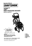
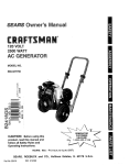
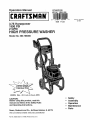
3.75 Horsepower
1500 PSI
2 GPM
P
WASH
Model No. 580.768000
HOURS:
Mon. - Fri. 8 a.m. to 5 p.m. (CST)
CAUTION:
Before using this product, read this
manual and follow all its Safety Rules
and Operating Instructions.
Sears, Roebuck and Co., Hoffman Estates, IL 60179
Visit our Craftsman website: www_sears°comJcraftsman
Part No, B3683 Draft 0 (11/4/98) Printed in the U,S.A,.
°
°
•
°
°
Safety
Assembly
Operation
Maintenance
Parts
Safety Rules ....................
Assembly .........................
Operation .......................
Maintenance
...................
LIMITED
2-3
4
5-8
9-12
ONE YEAR WARRANTY
Storage
.........................
Troubleshooting
...................
Replacements
parts .............
How to order parts and
request service
.............
ON CRAFTSMAN
HIGH PRESSURE
13
14
t 6-27
Back page
WASHER
For one year from the date of purchase, when this Craftsman High Pressure Washer is maintained and
operated according to the instructions in the owneCs manual, Sears will repair, free of charge, any defect in
material and workmanship.
This warranty does not cover:
• Expendable items such as spark plugs and air filters, which become worn during normal use.
° Repairs necessary because of operator abuse or negligence, including damage resulting
being supplied to pump or failure to maintain the equipment according to the instructions
owner's
manual.
WARRANTY SERVICE IS AVAILABLE BY RETURNING THE HIGH PRESSURE WASHER
NEAREST SEARS SERVtCE CENTER OR DEALER IN THE UNITED STATES.
This warranty gives you specific legal rights and you may also have other rights, which vary
state.
Sears,
,_
,_
•
Roebuck
and Co., Dept. 817WA,
CAUTION:
this Rules
product,
manual and Before
follow using
all Safety
andread this
Operating Instructions,
DANGER:
transporting,
setting
up,
adjusting orWhen
making
repairs to your
pressure
washer, always disconnect the spark plug wire
and place it where it cannot contact the spark
plug to prevent accidental starting°
Engine exhaust gases contain DEADLY carbon
monoxide gas,_This dangerous gas, if breathed in
sufficient concentrations, can cause
unconsciousness or even death. Operate this
equipment only in the open air where adequate
ventilation is available.
2
Hoffman
Estates,
from no water
contained in the
TO THE
from state to
IL 60179
•
Gasoline is highly FLAMMABLE and its vapors are
EXPLOSIVE. Do not permit smoking, open flames,
sparks or heat in the vicinity while handling
gasoline.. Avoid spilling gasoline on a hot engine,.
Allow unit to cool for 2 minutes before refueling.
Comply with all laws regulating storage and
handling of gasoline°
•
Locate this pressure washer in areas away from
combustible materials, combustible fumes or dust°
•
The high pressure equipment is designed to be
used with Sears authorized parts only. If you use
this equipment with parts that do not comply with
minimum specifications, the user assumes all risks
and liabilities.
°
Some chemicals or detergents may be harmful if
inhaled or ingested, causing severe nausea,
fainting or poisoning° The harmful elements may
cause property damage or severe injury.
•
Do not allow CHILDREN to operate the Pressure
Washer at any time..
•
Operate engine only at governed speed° Running
the engine at excessive speeds increases the
hazard of personal injury. Do not tamper with parts
which may increase or decrease the governed
speed,.
o
Never use a spray gun which does not have a
trigger lock or trigger guard in place and in
working order.
o
Use a respirator or mask whenever there is a
chance that vapors may be inhaled. Read all
instructions with the mask so you are certain the
mask will provide the necessary protection against
inhaling harmful vapors.
•
Do not wear loose clothing, jewelry or anything
that may be caught in the starter or other rotating
parts.
-
Before starting the Pressure Washer in cold
weather, check all parts of the equipment and be
sure ice has not formed there..
o
High pressure spray may damage fragile items
including glass.. Do not point spray gun at glass
when in the jet spray mode,.
•
Units with broken or missing parts, or without
protective housing or covers should NEVER be
operated°
The muffler and air cleaner must be installed and
in good condition before operating the Pressure
Washer° These components act as spark arrestors
if the engine backfires.
-
Keep the hose connected to machine or the spray
gun while the system is pressurized,,
Disconnecting the hose while the unit is
pressurized is dangerous..
o
Hold the spray gun firmly in your hand before you
start the unit. Failure to do so could result in an
injury from a whipping spray gun. Do not leave the
spray gun unattended while the machine is
running°
•
°
•
Check the fuel system for leaks or signs of
deterioration such as chafed or spongy hose,
loose or missing clamps or damaged tank or cap.
Correct all defects before operating the Pressure
Washer.,
o The cleaning area should have adequate slopes
and drainage to reduce the possibility of a fall due
to slippery surfaces..
Do not spray flammable liquids.
•
Keep water spray away from electric wiring or fatal
etectdc shock may result..
•
Do not secure tdgger gun in the pull-back (open)
position.
o Never allow any part of the body to come in
contact with the fluid stream. DO NOT come in
contact with a fluid stream created by a leak in the
high pressure hose.,
,
Do not by-pass any safety device on this machine.
°
High pressure streams of fluid this equipment
produces can pierce skin and its underlying
tissues, leading to serious injury and possible
amputation.
•
The muffler and engine heat up during operation
and remain hot immediately after shutting it down.,
Avoid contact with a hot muffler or engine or you
could be severely burned.
•
Never aim the gun at people, animals or plants.
•
Operate and store this unit on a stable surface.
o
High pressure spray can cause paint chips or
other particles to become airborne and fly at high
speeds°
o
•
Always wear eye protection when you use this
equipment or when you are in the vicinity where
the equipment is in use.
•
Operate the pressure at no more than the PSI fluid
pressure rated for your pressure washer.
°
Never move the machine by pulling on the high
pressure hose. Use the handle provided on the
top of the unit,,
High pressure hose can develop leaks from wear,
kinking, abuse, etco Water spraying from a leak is
capable of injecting material into skin,. Inspect
hose each time before using it., Check all hoses for
cuts, leaks, abrasions or bulging of cover, or
damage or movement of couplings. If any of these
conditions exist, replace hose immediately. Never
repair high pressure hose. Replace it with another
hose that meets minimum pressure rating of your
pressure washer°
°
Always be certain the spray gun, nozzles and
accessories are correctly attached.
LOOK FOR THIS SYMBOL TO POINT OUT IMPORTANT SAFETY PRECAUTIONS.
MEANS "ATTENTION!!! BECOME ALERT!!! YOUR SAFETY IS INVOLVED."
3
IT
CARTON
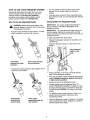
HOW TO SET UP YOUR PRESSURE
WASHER
CONTENTS
The following parts are shipped loose with your
pressure washer:.
= Main Unit-- pressure washer with wheels,
guide handle,,
High Pressure Hose
o Parts Box (which includes items listed below)
. Spray Gun
. Nozzle Extension
. Hi/Lo Adjustable Nozzle.
• Turbo Nozzle
o Engine Oil
• Manual Bag (which includes the items listed
below)
o Owner's Manual
° No_le Cleaner Kit
For the most part, your Craftsman High Pressure
Washer has been assembled at the factory. You must,
however, assemble the spray gun, and attach the high
pressure hose to the pump and spray gun.
°
, "O"-Ring Kit
Become familiar with each piece before assembling
the pressure washer° Check all contents against the
illustration on Page 5._If any parts are missing or
damaged, call the Pressure Washer Helpline at 1-800222-3136.
TO REMOVE
CARTON
PRESSURE
WASHER
FROM
= Remove loose parts and parts box included with
pressure washer..
° Slice two corners at guide handle end of carton
from top to bottom so the panel can be folded
down flaL
Raise guide handle, secure in place and roll the
pressure washer out the open end of the carton°
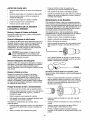
Cut the tie wraps on the high pressure hose and
connect high pressure hose to gun,. Tighten by hand..
•
Remove plastic cap and connect high pressure
hose to pump. Tighten by han&
The high
pressure outlet
is on this side of
the unit below
the engine
/
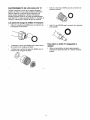
Attach nozzle extension to spray gun by aligning
the locking tabs on the extension with the grooves
in the gun. Push extension inward and twist
clockwise to lock in place.
Lift the handle to
upright position and
slide the locking
caps into place.
°
Attach desired nozzle onto nozzle extension._
°
Place assembled spray gun on holder.
Check carton for additional loose parts,.
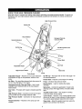
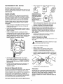
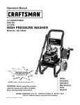
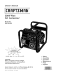
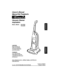
KNOW YOUR
HIGH PRESSURE
WASHER
Read this owner's manual and safety rules before operating your high pressure washer. Compare the
illustrations with your high pressure washer to familiarize yourself with the focations of various controls and
adjustments.
High Pressure Hose
Spray Gun
Recoil Starter
Detergent Pick-Up
Tube and Filter
NozzleO___-_
_Extension
_\\_"_X
Throttle Control Lever
Air Filter
Primer Bulb
Adjustable
Gas Tank
Nozzle
High Pressure Outlet
Turbo Nozzle
Waterlnlet
Pump
Adjustable Nozzle - Attaches to the nozzle extension
and adjusts for high or low pressure; narrow or fan
spray°
Oil Fill Cap - Fill engine with oil here,, See page 7 for
oil recommendations°
Air Filter - Dry type filter element limits the amount of
dirt and dust that gets in the engine.
Pump - Develops high pressure water
Primer Bulb - Prepares a cold engine for starting.
Recoil Starter - Used for starting the engine
manually,,
Detergent Pick-Up Tube and Filter - Use to suck
detergent from chemical bottle to the low pressure
water stream,,
Spray Gun - Controls the application of water onto
cleaning surface with trigger device. Includes safety
latch.
Gas Tank - Fill engine with regular unleaded gasoline
here.
Throttle Control Lever - Sets engine in starting
mode and stops running engine,,
Turbo Nozzle - Attaches to the nozzle extension and
allows you to clean or rinse surfaces at high pressure°
You cannot apply detergent using the turbo nozzle.
High Pressure Hose - Connect one end to the spray
gun and other end to the high pressure outlet.,
High Pressure
hose.,
Outlet - Connection for high pressure
Nozzle Extension - Attaches to the spray gun and
nozzles,,
Water Inlet - Attach the garden hose here using the
garden hose connector (not shown),,
5
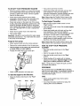
HOW TO USE YOUR
PRESSURE
For most effective cleaning, keep spray nozzle
between 8 to 24 inches away from cleaning
surface°
WASHER
Read these instructions and learn how to use your
pressure washer before you attempt to start your
pressure washer. If you have any problems
operating your pressure washer, please call the
pressure washer helpline at 1-800-222-3136.
If you get spray nozzle too close, especially using
high pressure mode, you may damage the cleaning
surface..
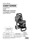
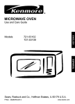
Cleaning With The Adjustable Nozzle
How To Use the Adjustable Nozzle
,_
o
IMPORTANT: Use soaps designed specifically for
pressure washers° Household detergents could
damage the pump.
WARNING:
Never
pattern
spraying., Never
putadjust
hands spray
in front
of thewhen
nozzle
when adjusting the spray..
IMPORTANT: You must attach all hoses before you
start the engine. Starting the engine without all the
hoses connected and without the water turned ON will
damage the pump.
Push the nozzle forward for tow pressure. Pull the
nozzle backward to achieve high pressure°
To apply detergent follow these steps:
•
Prepare the detergent solution as required by the
manufacturer.
o Hang the detergent solution on the hook on the
handle.
Hang detergent
bottle on this
hook.
Pull nozzle
backward for high
pressure.
Push nozzle forward
for low pressure.
Twisting the nozzle adjusts the spray pattem from a
narrow to a "fan" pattern.
Twist nozzle
clockwise for
narrow spray.
Twist nozzle
counterclockwise
"fan" pattern.
-
Place small filter on the clear, chemical injection
tube into the detergent container.,
*
Push the adjustable nozzle forward to low pressure
mode., Detergent cannot be applied with nozzle
in high pressure position.
°
Review the use of the adjustable nozzle.
°
Connect garden hose to water inlet (see 'q'O
START PRESSURE WASHER" on page 8), check
that high pressure hose is connected to spray gun
and pump (see ASSEMBLY on page 4), and start
engine°
°
For cleaning, start at lower portion of area to be
washed and work upward, using long, even
overlapping strokes.
Allow the detergent to soak in between 3-5 minutes
before washing and rinsing_ Reapply as needed to
prevent surface from drying.
for
6
Rinsing with the Adjustable
BEFORE STARTING
WASHER
Nozzle
WARNING: Be extremely careful if you must
use the pressure washer from a ladder,
scaffolding or any other relatively unstable
Iocation, When you press the trigger, the recoil
from the initial spray could force you to fall, or if
you are too close to the cleaning surface, high
pressure could force you off a climbing
apparatus.,
-
To operate the engine you will need to do the following:
Add Engine Oil
Only use high quality detergent oil rated with API
service classification SF or SG_ Select the oil's SAE
viscosity grade according to your expected operating
temperature:
colder
Hook up the water supply and start your pressure
washer (see TO START THE PRESSURE
WASHER on page 8).
°
_=,=.=== 32°F
-<
=,.===_ warmer
m
5W30
Pull adjustable nozzle backward to get high
pressure mode,, Wait for detergent to clear,,
Detergent witl not flow when in the high pressure
mode.,
>SAE 3O
Although multi-viscosity oils (5W30, 10W30, etc.)
improve starting in cold weather, these multi-viscosity
oils will result in increased oil consumption when used
above 32°F. Check your engine oil level more
frequently to avoid possible damage from running low
on oil
When detergent has cleared you may want to
expand the spray pattern for a more gentle rinsing
action° Start at top of area to be rinsed, working
down with same action as for cleaning,,
_lk
THE PRESSURE
°
Place pressure washer on a level surface
o Clean area around oit fill and remove oil dipstick°
CAUTION:
Test
a small,Make
hidden
the
surface
to be
cleaned,
surearea
thereof is
no
°
Wipe dipstick clean,,
-
Pour oil from enclosed bottle into the oil fill opening
until oil reaches full mark on the dipstick. Stop and
check the oil level periodically. Do not overfill.
°
Install oil dipstick, hand tighten securely,.
damage caused by the high pressure spray.
How to Use the Turbo Nozzle
The turbo nozzle rotates the high pressure stream in a
rapid circular pattemo The high pressure spray is most
effective when the tip of the wand is held between 8 to
24 inches from the surface being cleaned,,
Add Gasoline
•
Always start the turbo nozzle at a distance, gradually
getting closer to the surface until you get the cleaning
force you wahl
CAUTION! The turbo nozzle produces an
extremely high pressure spray which is capable
of removing paint and cutting holes through
surfaces if held too close,, Always make sure the
surface you will clean will not be damaged by
the high pressure spray by testing in a hidden
area.
Use regular unleaded gasoline with the pressure
washer engine. Fuel tank capacity is 1 USo quarL
_hk
DANGER:
Never
fill fuel
tank indoors.,
Never
fill
fuel tank when
engine
is running
or hot_
Do not
smoke when filling fuel tank.
_
AUTION:
Do expansion.
not overfill the fuel tank. Always
leave
room for
,_
CAUTION:
Experience
indicates
that alcohol
blended fuels
(called gasohol
or using
ethanol
or methanol) can attract moisture which leads to
separation and formation of acids during
storage. Acidic gas can damage the fuel system
of an engine while in storage.,
Note: You cannot apply detergent with the turbo
nozzleo
To attach turbo nozzle to spray gun:
o
Remove any accessories
extension,,
°
Attach turbo nozzle to nozzle extension.
To add fuel to engine:
attached to the nozzle
Connect the nozzle extension to the spray gun by
aligning the locking tabs on the accessory adapter
with the grooves in the gun., Push nozzle inward
and twist to lock in place_
o
Clean area around fuel cap, remove cap,
°
Add regular unleaded gasoline, slowly, to the fuel
tank.
Important;
°
7
Never mix oil with gasoline.
Install fuel cap and wipe up any spilled gasoline.
TO START
YOUR
PRESSURE
WASHER
•
Push primer bulb firmly (5) time&
•
Place the pressure washer in an area close enough
to an outside water source that can flow at a rate of
at least 2,2 gallons per minute. Connect a garden
hose to the water spouL
o Grasp rope handle and pull slowly untit you feel
some resistance. Then pull cord rapidly to
overcome compression, prevent kickback and start
the engine.. Let rope return to starter slowly,
-
Check that the high pressure hose is tightly
connected to the spray gun and to the pumF See
ASSEMBLY section on page 4 for illustrations.,
Check inlet screen on the water inlet. If the screen
is dirty, clean before attaching a garden hose° if the
screen is damaged, do not connect to the garden
hose. Replace with screen provided in maintenance
kit or call 1-800-366-PART to order a replacement
inlet screen.
Note: Always keep the Throttle Control Lever in the
'Fast' position when operating the pressure washer,,
•
°
To Start Engine Thereafter:
o Turn on the water.
Important:
Do not run pump without the water supply
connected and turned on° You must follow this caution
or the pump will be damage&
•
Remove the nozzle extension from the spray gun.
-
Pull the trigger on the spray gun and hold until
a steady stream of water appears.
-
Engage the safety latch on the spray gun°
•
Press the primer bulb 3 times. For a warm engine,
do not prime.
°
Purge air from pump:
Attach desired nozzle onto the nozzle extension..
Make sure the engine throttle control is in the
"Fast" position,
o Grasp rope handle and pull slowly until you feel
some resistance. Then pull cord rapidly to
overcome compression, prevent kickback and start
the engine. Let rope return to starter slowly,
Attach the the garden hose to the water inlet°
,
°
If engine fails to start, pull trigger on gun until a
steady stream of water appears, press the primer
bulb three more times and pull starter_
Note: Always keep the Throttle Control Lever in the
'Fast' position when operating the pressure washer..
HOW TO STOP
WASHER
YOUR
PRESSURE
°
Move the throttle control lever to the 'Slow'
position_
°
Wait for the engine to idle down_
•
Move the throttle control lever to the 'Stop'
position_
•
Simply shutting off the engine will not release
pressure in the system° Squeeze trigger on the
spray gun to relieve pressure in the hose.
Note: A small amount of water will squirt out when
you release the pressure.
SIPHONING
We recommend that you DO NOT siphon standing
water for your water supply° Contaminated, brackish or
dirty water can damage the pump. Connect 0nly to
household water supply.
o Attach nozzle extension onto spray gun°
To start the engine for the first time=
•
TIPS
Move the throttle control lever to the "Fast"
position°
Fast
Slow
•
Never use the garden hose inlet to siphon
detergent or wax..
,
If you have the spray nozzle too far away, the
cleaning will not be as effective.
Stop
8
CUSTOMER
RESPONSIBILITIES
MAINTENANCE
HOURLY OPERATING
INTERVAL
SCHEDULE
FiLL IN DATES AS YOU COMPLETE
REGULAR SERVICE
Be{ore Each
MAINTENANCE
ChecWclean
TASK
U,e
I
Every 25
t
i
Hours or
t
1
Yea"Y I
Ever]
SERVICE DATES
100
Hours or
Yea"v
water inlet screen
on quick-connect.
xt
Check high pressure hose_
x
iCheck detergent
hose.
x
iCheck spray gun and assemb{y for leaks,
x
x
Purge pump of air and contaminants.
ENGINE
Check oil level
x
i
l
i
i
X*
Change engine oil.
iService air cleaner.
Clean/replace
X
spark plug,
Prepare
Prepare for storage
remain
I_r
unit for storage
idle for longer
if it is to
than 30 days,
Clean if clogged, Replace if perforated or tom.,
Change oil after the first (5) operating hours and every 25 hours thereafter Change sooner when operating
conditions.,
under dirty or dusty
"* Replace more often under dirty or dusty conditions,
PRODUCT
SPECIFICATIONS
Pressure Washer Specifications
PRESSURE
...................................
1500 psi
FLOW RATE ........................................
DETERGENT
WATER
2 GPM
MIX .... Use undiluted deter eq._9___
SUPPLY
TEMPERATURE
......... Not to Exceed
140°F
In the State of California a spark arrestor is required
by Law (Section 4442 of the California Public
Resources Code). Other states may have similar laws,
Federal laws apply on federal lands.
Note: If you equip the engine of your pressure washer
with a spark arrestor muffler, the spark arrestor must
be maintained in effective working order by the
owner/operator.
You can order a spark arrestor (P/N 398067) through
your Sears Service Center_
GENERAL
Engine Specifications
ENGINE
MODEL ............... Briqcls &Stratton
RATED HORSEPOWER
SPARK
..........................
3.75
PLUG: Type: ....Champion RJ-19LM
or equivalent. Set
Gap to: ...0.030 inch
(0,76mm)
GASOLINE
CAPACITY
.......... 1.0 U.S. quart
OIL ...........................................
SAE 30 weiqht
SOLID STATE .................................
0°006IGNITION AIR GAP
.0i0 inch
RECOMMENDATIONS
The warranty of the high pressure washer does not
cover items that have been subjected to operator
abuse or negligence. To receive full value from the
warranty, operator must maintain high pressure
washer as instructed in this manual
Some adjustments will need to be made periodically to
properly maintain your high pressure washer,
All adjustments in the Service and Adjustments
section of this manual should be made at least once
each season,,
Once a year you should clean or replace the spark
plug and replace the air filter and check the gun,
nozzle extension and nobles for wear. A clean
spark plug and new air filter assure proper fuel-air
mixture and help your engine run better and last
longer.
BEFORE
•
EACH USE
Check water inlet screen for damage.
°
Pull the trigger on the gun and hold..
°
When the water supply is steady and constant,
engage the safety latch and refasten the nozzle
attachment.
o Check high pressure hose for leaks..
o Check detergent inlet hose and filter for damage_
= Check gun and nozzles for leaks.
°
Purge pump of air and contaminants.
°
Check engine oil level°
PRESSURE
WASHER
MAINTENANCE
Check and Clean Inlet Screen
Nozzle Maintenance
If the nozzle becomes restricted or clogged with
foreign materials, such as dirt, excessive pump
pressure may develop. A partially clogged nozzle can
cause a pulsing sensation during use. This generally
is not a pump related problem, but rather a clogged or
partially restricted nozzle.
Examine inlet screen_ C}ean if it is clogged or replace
if it is torn,
If the nozzle becomes clogged or partially restricted,
immediately clean the nozzle with the kit included with
your pressure washer by following these instructions:
Check High Pressure Hose
•
High pressure hose can develop leaks from wear,
kinking, or abuse.. Inspect hose each time before using
it,.Check for cuts, leaks, abrasions, bulging of cover,
or damage or movement of couplings. If any of these
conditions exist, replace hose immediately._
o Separate the nozzle extension from the gun_
_
Shut off the engine and turn off the water supply,,
=
•
Rotate to stream setting°
Remove nozzle from the end of the wand using the
allen wrench included with the kit or a 2mm or 5/64
allen wrench,.
•
Use the wire included in the kit or a small paper
clip to free the foreign materials clogging or
restricting the nozzle.,
ANGER:with
Never
a highthe
pressure
hose.,
Replace
hoserepair
that meets
minimum
pressure rating of your pressure washer
Check Detergent Hose
Examine the filter on the detergent hose and clean if
clogged. Hose should fit tightly on barbed fitting_
Examine hose for leaks or tears, Replace the filter or
hose if either is damaged,.
Check Gun and Nozzle Extension
Examine hose connection to gun and make sure it is
secure° Test trigger by pressing it and making sure it
springs back into place when you release ito Put safety
latch in UP position and test trigger,, You should not be
able to press trigger. Replace gun immediately if it
fails any of these tests,
Insert wire into nozzle and turn back and forth to
clear obstruction.
Remove additional debris by back flushing water
supply through wand. Back flush between 30 to 60
seconds. Turn wand to stream spray and move
nozzle from low to high pressure while flushing,.
Purge Pump of Air and Contaminants
To remove the air from the pump, follow these steps:
•
Set up the pressure washer as described in the
ASSEMBLY section on page 4 and connect the
water supply.,
°
Remove the nozzle extension from the gun_
°
Pull the trigger on the gun and hold until a steady
stream of water appears°
To remove the contaminants from the pump, follow
these steps:
•
Set up the pressure washer as described in the
ASSEMBLY section, and connect the water supply.
°
Remove the nozzle attachment from the gun°
°
Start the engine according to instructions in the
OPERATION section on page 5.
10
°
Reinstall nozzle into wand_ DO NOT overtighten_
•
Reconnect wand extension to spray gun.,
°
Reconnect the water supply, turn ON the water,
and start the engine,
•
Test the pressure washer by operating with nozzle
in the high and the low pressure positions_
O-Ring Maintenance
°
O-Ring, light green, (99794) for the male
accessory connections.
°
O-Ring, red, (B2726) for the nozzle extension
connection°
Through the normal operation of your pressure
washer, O-Rings, which keep the connections of the
hoses and gun tight and leak-free may become worn
or damaged, Provided with your pressure washer is
an O-Ring Maintenance Kit which provides
replacement O-Rings, Rubber Washer and water inlet
screen,.
Parts in the O-Ring Kit Include:
o O-Rings, yellow, (pin B2264) for the ends of the
high pressure hose.
To remove a worn or damaged O-Ring:
o 1 rubber washer (p!n B2385) for the inside of the
garden hose connector.
o
o 1 water inlet screen (pin B2384) for the garden
hose connector.
11
Use a small flathead screwdriver to get
underneath the o-ring and pry it off_
ENGINE
MAINTENANCE
Checking Oil Level
Oil level should be checked prior to each use or at
least every (5) hours of operation_ Keep oil level
maintained.
_SW
BOO_y_
LIP
Changing Oil
SO LIP EXTENDS
OVER EOGE OF
AfR CLEANER BODY
Change engine oil after the first (5) hours and every
(25) hours thereafter. If you are using your pressure
washer under extremely dirty or dusty conditions, or in
extremely hot weather, change oil more often,
LIP W}LL FORM
ASSEMBLE
PROTECTIVE
ELEMENT
SEAL
WHEN COVER
IS ASSEMBLED
Change oil while engine is still warm from running, as
follows:
°
Remove dirty
air cleaner carefully to prevent debris
from falling into carburetor,.
o
°
Take cleaner apart and clean all parts_
•
°
Drain fuel tank by running pressure washer until
fuel tank is empty.
Clean area around oil fill, remove oil fill
cap!dipstick,, Wipe dipstick clean.
To service foam element, wash in liquid detergent
and water° Squeeze dry in a clean cloth° Saturate
in clean engine oil., Squeeze in clean cloth to
remove all excess oil Replace foam element if
very dirty or damaged.
Tip your pressure washer to drain oiI from the oil fill
tube into a suitable container making sur you tip
your unit away from the spark plugo.,When
crankcase is empty', return the pressure washer to
upright position°
°
Reassemble all parts and fasten securely to the
carburetor with screw.
Clean / Replace Spark Plug
SPARK PLUG
Clean or replace the spark plug yearly or every 100
hours of operation,
_k
CAUTION:
Disconnect
spark
wire
fromplug_
spark plug and
keep wire
awayplug
from
spark
o
Clean area around spark plug.
o
Remove and inspect spark plug,
l
Replace spark plug if the electrodes are pitted,
bumed or porcelain is cracked. For replacement
use Champion RJ-19LM only.
•
Check electrode gap with wire feeler gauge and set
gap at °030" if necessary.
°
install spark plug, tighten securely.
Fitl engine crankcase with recommended oil until oil
level is at FULL point on dipstick. Do not overfill
above that mark. POUR SLOWLY.
When engine crankcase is filled to proper level,
install and tighten oil capldipstick_
Service Air Cleaner
Your engine witl not run property and may be
damaged if you run it with a dirty air cleaner.
Clean the air cleaner once every (25) hours of
operation or once each year, whichever comes first_
Clean more often if operating under dirty or dusty
conditions. Replacements are available at your local
Sears Authorized Service Center°
Carburetor
If you think your carburetor needs adjusting, see your
nearest Sears Service Center_ Engine performance
should not be affected at altitudes up to 700 feet° For
operation at higher elevations, contact your nearest
Sears Service Center.
To clean the air cleaner, follow these steps:
°
Remove screw on the air cleaner cover.
!2
AFTER
EACH USE
It is important to prevent gum deposits from forming in
essential fuel system parts such as the carburetor, fuel
filter, fuel hose or tank during storage,. Also,
experience indicates that alcohol-blended fuels (called
gasohol, ethanol or methanol) can attract moisture
which leads to separation and formation of acids
during storage° Acidic gas can damage the fuel system
of an engine while in storage,.
Water should not remain in the unit for long periods of
time. Sediments of minerals can deposit on pump
parts and "freeze" pump action° Follow these
procedures after every use:
•
Flush detergent hose by pfacing the injector filter
into a pail of clear water while running Pressure
Washer with nozzle in low pressure modemFlush
until you can see clear water running through the
tube°
o
Protect Fuel System
Shut off the engine and let it cool, then remove all
hoses°
,_
,_
= Remove all gasoline from the fue! tank to prevent
gum deposits from forming on these parts and
causing possible malfunction of engine_
CAUTION:
Be sure
Run/Stop
Lever
is in
the
"Stop"
position
beforetheyou
continue°
If you
start
the engine without the proper water supply
connected, you can damage the pump..
o
Empty the pump of all pumped liquids by pulling
recoil handle about 6 times with the Run/Stop Lever
in the "Stop" position. This should remove most of
the liquid in the pump°
°
Coil the high pressure hose and inspect it for
damage° Cuts in the hose or fraying of it could
result in leaks and loss of pressure. Should any
damage be found, replace the hose. DO NOT
attempt to repair a damaged hose. Replace the
hose with the genuine Craftsman part.
°
DANGER:
Drainfrom
fuel open
into approved
outdoors, away
flame° Becontainer
sure
engine is coolo Do not smoke°
°
Run engine until engine stops from lack of fuel.
Make sure you have water supply to pump inlet
connected and turned ON.
Change Oil
While engine is still warm, drain oil from crankcase_
Refill with recommended grade° (See Changing Oil on
Page 12,,)
Oil Cylinder Bore
•
Drain water from hose and properly hang it on the
wire support provided on the guide handle..
Remove spark plug and pour about 1 ounce (30 ml)
of engine oil into the cylinder. Cover spark pkJg
hole with rag° Crank slowly to distribute oil.
Store in a clean, dry area°
,_
,_
DANGER:
store
engine with
fuel in
the
gas tankNever
indoors
or the
in enclosed,
poorly
ventilated areas where fumes may reach an
open flame, a spark, or pilot light,.
WINTER
_1
°
Install spark plug., Do not connect spark plug wire,.
OTHER
STORAGE
AUTION:
You must protect
unit
freezing
temperatures,
Failureyour
to do
sofrom
will
permanently damage your pump and render
your unit inoperable°
To protect the unit from freezing temperatures:
-
CAUTION:
Avoid
sprayslowly.
from spark plug hole
when cranking
engine
Draw RV-Antifreeze (antifreeze without alcohol)
into the pump by pouring the washer fluid into a 3foot section of garden hose connected to the inlet
adapter and pulling the recoil handle twice.
•
Do not store gasoline from one season to another_
°
Replace your gasoline can if your can starts to rusL
Rust and/or dirt in your gasoline will cause
problems°
.
If possible, store your unit indoors and cover it to
give protection from dust and dirt,, BE SURE TO
EMPTY THE FUEL TANK,,
°
Cover your unit with a suitable protective cover that
does not retain moisture.
IMPORTANT: NEVER cover your pressure washer
while engine and exhaust area are warm.
LONG TERM STORAGE
if you do not plan to use the Pressure Washer for
more than 30 days, you must prepare the engine for
long term storage.
Note: As always, prepare the pressure washer pump
as you would after each use..
!3
CORRECTION
CAUSE
PROBLEM
1,, Nozzle in low pressure mode_
1o Pull nozzle backward for high
erratic pressure, chattering, loss of
2, Water inlet is blocked,,
pressure mode.
2,, Clear inlet
pressure, low water volume.,
3,
3,, Provide adequate water flow at
Pump has following problems:
failure to produce pressure, or
Inadequate water supply
least 2 gpmo
4_ Inlet hose is kinked or leaking
4.
5
5,, Replace / clean water inlet
Clogged water inlet screen._
Straighten
inlet hose, patch leak.
screen,,
6,, Water supply is over 140°F,.
7, Outlet hose is blocked,,
6.. Provide cooler water supply_
7,, Clear blocks in outlet hose.
8., Outlet hose leak&
8,
Replace outlet hose if leaking.
9,
Gun leaks..
9.
Replace o-ring or gun if
10
Nozzle is obstructed.,
necessary,
10,. Clear nozzle,,
11
Pump is faulty,
11,, Contact Sears Service
Detergent fails to mix..
.,
Department,
1., Insert chemical line into
Detergent line is not submerged.
detergent,
detergent.,
2_
Chemical filter is clogged.,
3,,
Nozzle is in high pressure mode.
2_ Clean or replace filter/detergent
line,,
3, Push nozzte forward for
low pressure mode,
Engine speed is too slow.,
Contact Sears Service Department.
Engine will not start; or starts
t.,
Dirty air cleaner
and runs rough
2.
Out of gasoline.,
1_ Clean or replace air cleaner_,
2,, Fill fuel tank.,
3,
Stale gasoline,
&
Drain gas tank; fill with fresh fuel
4.
Spark plug wire not connected
4.
Connect wire to spark plug_
Engine runs good when not spraying
but dies when you begin to spray.,
to spark plugo
5o Bad spark plug.
5,, Replace spark plug,
6.. Water in gasoline
6o Drain gas tank; fill with fresh fuel.
7.
7,, Set engine throttle control lever to
Overchoking
or flooded
fast position, choke in run
8,
9.
Excessively
rich fuel mixture,.
Intake valve stuck open or closed,.
8,
position.
Contact Sears Service
9,
Department.,
Contact Sears Service
Department,.
10., Contact Sears Service
10. Engine has lost compression..
Department.
, LI,
Engine shuts down during
operation
1.
2.
Out of gasoline..
Air filter dirty
Engine lacks power.
Dirty air filter,
,,,,,,,i
1.
Fill fuel tank.,
2.
Replace Air filter.
Replace air filter,
14
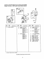
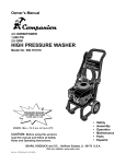
Craftsman 1800 PSI High Pressure Washer 580.768000
Briggs & Stratton 3.75HP Sprint, Model 98902-2228-E2
305 Yr
REQUIRES
SPECIAL
TOOLS
TO INSTALL
SEE REPAIR
INSTRUCTION
MANUAL.
116_
635 3_
7
10
REE
NOD
PART
NO._
1
2
399164
293708
3
5
.299819
214277
272694
REE,
NO,
DESCRIPTION
Cylinder Assembly
Bushing
Seal-Oil
116
Head-Cylinder
Note
213942 Head-Cylinder
(Used Before Code
Date 96080100),,
Gasket-Cylinder
Head
Note
,272536 GasketCylinder Head
(Used Before Code
Date 96080100),
9
10
11
13
37
37A
37B
51
54
,
Breather Assembly
(Includes Gasket)
*272602 Gasket-Breather
94621 Screw-Hex,,
231774 Tube-Breather
93111 Screw-Hex
223150 Guard-Flywheet
224819 Guard-F3ywhee]
225013 Guard-Rywheel
*270345 Gasket-lntake
93485 Screw-Hex.
inctuded in Gasket Set-Part
_271485
200
284
305
335
337
281024
94073
94786
94732
802592
383
89838
523A
495785
PART
NO.
DESCRIPTION
REF,
NO,,
Blade-Governor
Screw-Shoulder
Screw-Hex
Screw-Shoulder
Plug-Spark
(Resistor Type)
_
Note
492167 Rug-Spark
Wrench-Spark Plug
28108'1 Dipstick
298775
66538
Manifold-Intake
869
211172 Seat-Valve
870
211291
871
231348
Boot-Spark
Plug
(Intake)
Seat-Valve
(Exhaust)
Brushing-Guide
(Exhaust)
No,, 298989,
Assemblies include all parts shown in frames.
!5
DESCRIPTION
Note
Sea!-O Ring
625
635
PART
NO,
63709 Bushing-Guide
(intake)
Craftsman 1800 PSI High Pressure Washer 580.768000
Briggs & Stratton 3.75HP Sprint, Model 98902-2228-E2
24
45
741
377
357_
REF..
NO.
16
PART
NO
492748
REF
NO
DESCRIPTION
Crankshaft
24
25
PART
NO,
222698
498668
DESCRI PTION
REE
NO,,
27
28
Key-F[ywheef
Piston Assembly
(Standard)
498669 Piston Assy
(O10" O.S,)
498670 Piston Assy
(,020" O_,S,)
498671 Piston Assy,
PART
NO.,
26026
298909
498680
(oo5"o.,sJ
29
Ring Set
(Standard)
498681 Ring Set
(.O10"O.S,)
498682 Ring Set
(O20"O.,S,.)
498683
Ring Set
(.,030"OS.
*
included in Gasket Set-Part
294201
32
94699
33
34
35
40
45
296676
296677
260552
93312
230173
499047
91539
718
357
377
741
No. 298989,,
Assemblies include all parts shown in frames,,
16
Lock-Piston Pin
Pin-Piston
(Standard)
298908 Pin-Piston
(.o3o"o s,)
26
DESCRIPTION
93065
261533
Rod-Connecting
296079 Rod-*
Connecting
(,020" Undersize)
Screw-Connecting
Rod
Valve-Exhaust
Valve-lnlake
Spring-Valve
Retainer-Valve
Tappet-Valve
Pin-Crankshaft
Key-Drive Pulley
Key-Woodruff
Gear-T_ming
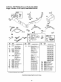
Craftsman 1800 PSI High Pressure Washer 580.768000
Briggs & Stratton 3.75HP Sprint, Model 98902-2228-E2
REQUIRES SPECIAL TOOLS 220 _)
TO INSTALL. SEE REPAIR
INSTRUCTION
MANUAL.
46A
12oi.1
220 (_)
72 "1
22
10A_
REF,
NO,
PART
NO,
REE
NO,,
DESCRIPTION
:
4
4A
10A
12
395384
395390
94658
*270833
Sump-Engine
Sump-Engine
,
46A
Include(s):
391484 Sea,Oil
Screw-Hex_
Note
94621 Screw-He_.
47
83
REF
NO
PART
NO.,
,
94720
293709
20
20A
22
22A
46
*391483
391484
94682
93415
493747
396197 Gear-Cam
(Clockwise)
491688 Slinger-Oil
230831 Shaft-Aux.. Drive
(Used Before Code
Date 96112000)
Gasket-Crankcase
( 015" Thick, Standard)
*270895 GasketCrankcase
(009" Thick)
Plug-O{| Drain
Bushing
(PIain)
Seal-Oil
Sea!-Oit
Screw-Hex.
Screw-Hex_
Gear-Cam
. Included in Gasket Set-Part
No. 298989_
Assemblies
DESCRIPTION
,
(,.005" Thick)
*270896 GasketCrankcase
15
19
PART
NO,
include all parts shown in frames.
17
88
220
720
.270328
68938
93474
Gasket-Cover
Washer-Thrust
Pin-Shaft
721
743
221779
231278
Stop-Shaft
Gear-Drive
784
221780
Cover-Gear
Craftsman 1800 PSI High Pressure Washer 580.768000
Briggs & Stratton 3.75HP Sprint, Model 98902-2228-E2
617
393
REF,
NO,,
PART
NO,,
96
125
224412
498809
131
163
281047
,271139
REE
NO,.
DESCRIPTION
PART
NO,
DESCRIPTION
Valve-Throttle
Carburetor
Note
494775 Carburetor
190
390
93440
262764
393
262734
(Used Before Code
Date 96052000),
Shaft-Throttle
Gasket-Air Cleaner
394
495770
529
612
67838
496046
DiaphragmCarburetor
Grommet
Tube-Pickup
include
all parts shown
REF,
NO,.
Screw-Phi!tips
Spring-Choke
Diaphragm
Screen-Carburetor
. Included in Gasket Set-Part No 298989,,
Assemblies
18
in frames.
PART
NO.,
DESCRIPTION
617
634
913
270344
280566
494409
Seat-intake
Manifold
Washer-Foam
Seat-Check Valve
973
281661
976
494408
Ring-Trim
(Primer Bulb).
Prime{-Carburetor
Craftsman 1800 PSI High Pressure Washer 580.768000
Briggs & Stratton 3.75HP Sprint, Model 98902-2228-E2
482 '
621
305
356A
356
271
268
334 _'
269
62'1
209_
RER.
NO..
*
PART
NO,.
RER.
NO,.
DESCRIPTION
201
209
262753
Link-Air Vane
Spnng-Governor
See Last Pages
Spring-Governor
Link-Lock Out
Screw-Hex_
209A
236
258
263109
262461
94018
268
66986
269
26099
Casing-Wire
(48" Long)
(Cut to Required
Length),.
Wire-Control
270
271
305
307
63426
290566
94786
94515
(54" Long)
(Cut to Required
Length).
Locknut-Casing
Lever_._;ontrol
Screw-Hex.
Screw-Hex°
333
334
398593
94731
Armature-Magneto
$crew-Hex..
356
356A
482
398808
496381
93621
Wire--Stop
Wire-Step
Screw-Hex..
included in Gasket Set-Part
620
PART
NO..
498206
DESCRIPTION
REF.
NO
DESCRIPTION
Bracket.q3ontrol
(Used After Code Date
96040700).
Note
495485 BracketControl
(Used Before Code
Date 96040800).
0151,0165,0t66,
0167.0197.0199,
0300,0310,0312,
0313+0314,0317,
0319,0320,0321,
0323,0325,0330,
0334,0337,0341,
0350,0355,0360,
498207 BracketControl
(Used Alter Code Date
96040700)..
495486 BracketControl
0361,0362,0365,
0370,0371.0376,
0379,0380,0383,
0388,0390,0391,
0392,0393,0394,
0396,0397,0398,
(Used Before Code
Date 96040800)..
Used on Type No(s).
0101, 0110, 0114,
0117, 0119, 0121,
0123, 0!25, 0126,
0127, 0t28, 0129,
0130, 0!31, 0133,
0134, 0t40, 0142,
0147, 0t48, 0150,
No. 298989
Assemblies
PART
NO.
include all parts shown in frames.
19
621
729
851
922
923
933
396847
280470
493880
261647
394867
223448
934
941
94037
281285
942
493248
0399.0891,0899
Switch-Stop
Clip-Wire
Termina!-Cable
Spdng-Brake
Brake
Pivo_Band B_ke
Screw-Phi!lips
Cover-Linkage
Bracket-Brake
Craftsman 1800 PSi High Pressure Washer 580.768000
Briggs & Stratton 3.75HP Sprint, Model 98902-2228-E2
670
REE,
NO.
PART
NO.,
13
93111
181A
305
499125
94'786
.
REF
NO.
DESCRIPTION
Screw-Hex,
670
PART
NO.
94047
Cap-Fuel Tank
Screw-Hex
REF
NO,,
DESCRIPTION
Spacer-Fuel Tank
Used on Engines
Without Band Brake,,
Note
94038 Spacer
Used on Engines With
Band Brake,
Includedin Gasket Set-Part No, 298989,,
Assemblies
include
all parts shown
20
in frames.
957
PART
NO,
497929
DESCRIPTION
Cap-Fuel
Tank
Craftsman 1800 PSI High Pressure Washer 580.768000
Briggs & Stratton 3.75HP Sprint, Model 98902-2228-E2
298 @
534!
REF,
NO,,
PART
NO,
REF
NO
DESCRIPTION
298
220859
Locknut-Mufller
300A
394569
346
93705
Muffler-Exhaust
(LO Tone)
Screw-Hex.
300A@
PART
NO-,
DESCRIPTION
436
534
535
536
92989
93865
272235
493492
Elbow-Exhaust
Screw-Slotted
Filter-Air
Cleaner-Air
643
676
280972
396548
Retainer-Air Ftter
Deflector-Muffler
REF
NO,
393760
393756
397931
Deflector-Muffler
Deflector-Mufller
Deflector-Muffler
832A
498145
398067
Guard-Muffler
Arrestor-Spark
include all parts shown in frames.
2!
DESCRIPTION
676A
676B
676C
* includedin Gasket Set-Part No 298989
Assemblies
PART
NO,,
994
Craftsman 1800 PSI High Pressure Washer 580.768000
Briggs & Stratton 3.75HP Sprint, Model 98902-2228-E2
949
949A
332
74_
68
455_
57
1016
7sQ
56
58
REF
NO,
PART
NO..
23
495046
56
57
58
*
281336
490179
280405
REF
NO.
DESCRIPTION
PART
NO
-w
Flywheel
Pulley-Starter
Spr_ng-Rewind Starter
Rope-Starter
(81" Long)
(Cut to Required
Length)
REF
NO.
DESCRIPTION
Note
280399 Rope-Star_er
(99" Long)
PART
NO.
267
305
94694
94786
Screw-Slotted
Screw-Hex.,
Nut-Flywheel
Flywheel Puller
Cup--Flywheel
Starter-Rewind
See Last Pages
Guard-Rewind
332
92284
(Cut to Required
Length}
363
455
19069
225121
608
59
60
65
66
396892
393152
94680
399671
lnsert-.Grip
Grip-Starter
Screw-Hex,
Ctutch-,Statter
67
68
70
71
394897
63770
298799
394506
Housing-Clutch
Bali-Clutch
Ratchet.---Clutch
Cover-Ratchet
73
74
221661
93758
Screen-Rotating
Screw-Hex
75
76
223047
68238
Washer-Flywheel
Seal
265
268A
22372
213146
C|amp-Casing
Clamp-Casing
Assemblies
include
Rope
949
281337
949A
281279
1016
281353
1036
499331
22
Hex_,
Guard-Finger
Spacer-Rewind
(2-13116" Dia,)
Label Kit-Emission
Used on Type No(s)
0810, 0837, 0849,
0865, 0866, 0891,
0899_ 1446, t472.
1477. t515, 1516,
1518. 1551, 1644.
Included in Gasket Set-Part No, 298989.,
all parts shown
DESCRIPTION
in frames.
Craftsman 1800 PSi High Pressure Washer 580.768000
Briggs & Stratton 3.75HP Sprint, Model 98902-2228-E2
Ul
ul
,,,_,
358 GASKET
SET
116 (_
163 (__
12
REE
NO.,
PART
NO.
REF_
NO.
DESCRIPTION
3
*299819
Seal-Oil
7
*272536
Gasket-Cylinder
Head
(Used Before Code
Date 96080100)..
Gasket-Breather
Gasket-Crankcase
9
12
,272602
*270833
PART
NO..
DESCRIPTION
REE.
NO.,
_270895 GasketCrankcase
(005" Thick)
*270896 GasketCrankcase
(.,009" Thick)
( 015" Thick, Standard)
. Included in Gasket Set-Part No 298989.
Assemblies
include all parts shown
23
in frames.
PART
NO.,
DESCRIPTION
20
51
88
*391483
*270345
*270328
Seal-Oil
Gasket-Intake
Gasket-Cover
116
i63
358
*271485
*271139
298989
SeaI-O Ring
Gasket-Air Cleaner
Gasket Set
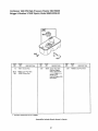
Craftsman
1800 PS! High Pressure
Washer
580.768000
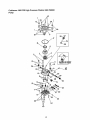
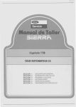
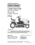
Pump
_2
=\,39
_
16
7
39
24
_9/I
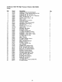
Craftsman 1800 PSI High Pressure Washer 580.768000
Pump
Item
1
2
3
4
5
6
7
8
9
10
11
t2
13
14
15
•16
17
18
19
20
21
23
24
25
26
27
28
29
30
31
32
33
34
35
36
37
39
40
41
42
43
44
45
Pa_ #
96795
21640
21641
21642
93680
99503
93667
98304
98227
20110
97830
97831
97832
A1111b
57018
21429
97835
97837
97838
97839
97840
97841
97842
97843
B1253
97845
A2731
97847
A2730
21424
A1575
96137
95379
95380
20631
97934
93873
40946
97851
97962
21783
20876
B1077
Description
SLEEVE, Rubber Grommet Spacer
ASSEMBLY, Cage Needle Bearing 45 x 65
WASHER, Brg.. Dia_ 45 x 65 x 1T
WASHER, Brg. Dia, 36 x 65 x 6T [Special]
SEAL, Oil Piston Dia. 15
SPRING, Piston Return - EG
SEAL, U-Clip
CAM, Axial &6mm w/insert
ADAPTER, Engine
HOUSING, Piston and Unloader
RETAINER, Piston Spring
SPACER, Pilot
PISTON, Diao 15-65 Long
HEAD, Pump
BEARING, Ball Radial
BUSHING, Rubber
"O" RING, Housing Seal
=O" RING, Hi-Pressure Transfer
ASSEMBLY, Check Valve - Inlet
ASSEMBLY, Check Valve - Outlet
"O" RING, Inlet Port Cap
CAP, Inlet Port
SEAT, Unloader
"O" RING, Unloader Venturi
PISTON, Unloader
SEAL, Unloader "Parback"
SPRING, Unloader
"O" RING, Unloader Cap
CAP, Unloader
CONNECTOR, Garden Hose
BARB, Hose with Nylon Insert
PLUG, '1/8" NPT [with Sealant]
BALL, Diao &5 Chemical Injector
SPRING, Chemical Injector
VENTURI, Chemical Injector
"O" RING, Check Valve - Inlet
LOCK WASHER, M6 Ribbed
SHCS, M6-1o0 x 35mm
"O" RING, Piston Housing
SHCS, M6-1o0 x 25mm
THERMAL RELIEF
.5 oz.. SEALANT, Thread Locktite 545
"O" RING, Venturi
25
3
1
I
1
3
3
3
1
1
1
3
3
3
1
1
6
1
1
3
3
3
3
1
1
1
2
1
1
1
1
1
1
I
1
1
3
7
4
3
3
1
0
1
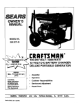
Craftsman
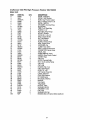
Main Unit
1800 PSI High Pressure
Washer
580.768000
46
3O
28
19
31
20
tt
18
21
22
35
26
Craftsman
Main Unit
ITEM
2
3
4
5
6
7
8
9
10
11
12
'13
14
t5
16
t7
t8
19
20
21
23
24
25
26
27
28
29
30
31
32
33
34
35
36
37
38
39
4O
41
42
43
44
4.5
46
47
900
1800 PSI High Pressure
PART NO,
B3220
963,07
DB3307A
1_30_5
B3685
30809
B1786A
21206
75402
52858
27007
57821
B1735
B1880
A1040B
A104!
98300
B1797
48031G
B1262A
21424
91373
79552
DB3330
B2791
B2790
B2759A
B2071
81895
B2516
B3381G
97100
B,3,337
At408
21337
21336
B2739
B3708
B3683
96382
97566
BI&00G
50190
Bl127
B1460
49808
NSP
QT
1
1
1
1
1
1
1
2
2
2
2
2
3
3
t
1
1
4
1
1
1
1
t
1
2
2
1
2
2
3
1
1
1
1
1
1
1
1
t
1
1
1
2
1
1
2
1
Washer 580.768000
DESCRIPTION
DECAL, lnstrd_ons
DECAL, 1-800 Number
BASE, Gray Powder Coated
BOLT, Carriage 1/4-20 x 1,50
DECAL, 1800 PSI
GROMMET, Chemical Hose
BILLBOARD
TIRE, 2"x 8" Black Mag
PUSHNUT, !/2"
NUT, M8 Locking Flange
MouNq', Vibration
HHCS, M8 - 125 x 40
STUD, Double Ended
NUT, with Washer
HOSE, Chemical
FILTER, ChemicBJHose
SEAL, Engine Donut
FASTENER, Clip
CLAMP, Hose 13/16"
ASSYo,Pump EG w/Thermal
CONNECTOR, Garden Hose
DECAL, Data
OVERLAMINATE, Decal
HANDLE, Gray Powder Coated
COVER, Hinge
CAP, End
HOOK, Chemical BoWe
NUT, 1/4-20 Locking Range
CAP, Ptug
CAP, Vinyl
NOZZLE, High / Low
CAP, High Pressure
HOSE, I/4" x 25'
CAP, Garden Hose Inlet
LANCE, Extension
GUN, High Pressure
KIT, Maintenance
KIT, NozzJe,Cleaning
MANUAL
O_L,Engine
TAG, NozzJe
NOZZLE, Turbo
WASHER, M8 Fiat
GROMMET, Turbo
CAP, Vinyl
WASHER, M12 Flat
ENGINE, B&S 3,75 Sprint, 98902-2228-E2
27
Briggs & Stratton Corporation (B&S),
the California Air Resources Board
(GARB) and the United States
Environmental Protection Agency (U.S.
EPA)Emission Control System
Warranty Statement (Owner's Defect
Warranty Rights and Obligations)
In the interest of the environment,
Briggs &
Stratton engines that meet strict emission
requirements are labeled, 'qhis engine
conforms to 1995-I 998 California Emission
Control Regulations
for ULGE engines and
U.S. EPA Phase 1 regulations for small nonroad engines." EMISSION CONTROL
WARRANTY COVERAGE
IS APPLICABLE
ONLY TO CERTIFIED
ENGINES
PURCHASED
IN CALIFORNIA
IN 1995 AND
THEREAFTER
WHICH ARE USED IN
CALIFORNIA
AND TO CERTIFIED MODEL
YEAR 1997 AND LATER ENGINES WHICH
ARE PURCHASED
AND USED
ELSEWHERE
IN THE UNITED STATES.
California and United States
Emission Control Defects Warranty
Statement
CARB, U.S. EPA and B&S are pleased to
explain the Emission Control System
Warranty Statement on your 1996 and later
utility or lawn and garden equipment (ULGE)
engine. In California, new ULGE engines
produced on or after August 1, 1995 must be
designed, built and equipped to meet the
State's stringent anti-smog standards.
Elsewhere in the United States, new nonroad, spark-ignition
engines certified for
model year 1997 and alter, must meet similar
standards set forth by the UoS. EPA. B&S
must warrant the emission control system on
your engine for the periods of time listed
below provided there has been no abuse,
neglect or improper maintenance of your
ULGE engine.
Your emission control system includes parts
such as the carburetor, air cleaner, ignition
system, muffler and catalytic converter. Also
included may be connectors
and other
emission related assemblies.
Where a
warrantable
condition exists, B&S will repair
your ULGE engine at no cost to you including
diagnosis, parts and labor.
Briggs and Stratton Emission
Control Defects Warranty Coverage
ULGE engines are warranted relative to
emission control parts defects for a period of
two years, subject to the provisions set forth
below. If any covered part on your engine is
defective, the part will repaired and replaced
by B&S.
Owner's
Warranty
Responsibilities
As the ULGE engine owner you are
responsible for the performance
of the
required maintenance
listed in your
Operator/Owner
Manual. B&S recommends
that you retain all of your receipts covering
maintenance
on your ULGE engine, but B&S
cannot deny warranty solely for the lack of
receipts or for your failure to ensure the
performance
of all scheduled maintenance.
As the ULGE engine owner, you should
however be aware that B&S may deny you
warranty coverage if your ULGE engine or a
part has failed due to abuse, neglect,
improper maintenance or unapproved
modifications.
You are responsible for presenting your
ULGE engine to an Authorized B&S Service
Dealer as soon as a problem exists. The
undisputed
warranty repairs should be
completed in a reasonable amount of time,
not to exceed 30 days.
If you have any questions regarding your
warranty rights and responsibilities,
you
should contact a B&S Service Representative
at 1-414-259-5262.
28
The emission warranty is a defects warranty.
Defects are judged on normal engine
performance° The warranty is not related to
an in-use emission test.
3. No Charge
Repair or replacement of any Warranted
Part will be performed at no charge to the
owner, including diagnostic labor which
leads to the determination
that a
Warranted
Part is defective, if the
diagnostic work is performed at an
Authorized
B&S Service Dealer. for
emissions warranty service contact your
nearest Authorized B&S Dealer as listed
in the "Yellow Pages" under "Engines,
Gasoline," "Gasoline Engines," "Lawn
Mowers" or similar category.
Briggs and Stratton Emission
Control Defects Warranty Provisions
The following are specific provisions relative
to your Emissions Control Defects Warranty
Coverage° it is in addition to the B&S engine
warranty for non-regulated
engines found in
the Operator/Owner's
Manual
1. Warranted Parts
Coverage under this warranty extends
only to the parts listed below (the
emission control systems parts) to the
extent these parts were present on the
engine purchased.
a.
Fuel Metering
system
and internal
(soft
parts
• Fuel Pump
b°
Air Induction
° Air cleaner
System
° Intake manifold
o Spark Plugs
d.
Catalyst
o Catalyst
° Exhaust
e.
ignition system
System
converter
manifold
• Air injection
Miscellaneous
Systems
o Vacuum,
sensitive
system or pulse valve
Items Used in Above
temperature, position,
valves and switches
° Connectors
Exclusions
Any Warranted Part which is not
scheduled for replacement as required by
maintenance
or which is scheduled only
for regular inspection to the effect of
"repair or replace as necessary" shall be
warranted as to defects for the warranty
period. Any Warranted part which is
scheduled for replacement as required by
maintenance
shall be warranted as to
c. Ignition system
• Magneto
and Coverage
Warranty claims should be filed in
accordance with the provisions of the B&S
Engine Warranty Policy. Warranty
coverage shall be excluded for failures of
Warranted
Parts which are not original
B&S parts or because of abuse, neglect or
improper maintenance
as set forth in the
B&S Engine Warranty Policy. B&S is not
liable to cover failures of Warranted
Parts
caused by the use of add-on, non-original,
or modified parts.
5. Maintenance
System
o Cold start enrichment
choke)
• Carburetor
4. Claims
defects only for the period of time up to
the first scheduled replacement for that
part. Any replacement part that is
equivalent in performance
and durability
may be used in the performance
of any
maintenance
or repairs. The owner is
responsible for the performance of all
required maintenance,
as defined in the
B&S Operator/Owner
Manual.
time
and Assemblies
2. Length of Coverage
B&S warrants to the initial owner and
each subsequent purchaser that the
Warranted Parts shall be free from defects
in materials and workmanship which
caused the failure of the Warranted Parts
for a period of two years from the date the
engine is delivered to a retail purchaser.
6,
Consequential
Coverage
Coverage here under shall extend to the
failure of any engine components
caused
by the failure of any Warranted Part still
under warranty.
29
For in-home major brand repair service:
Call 24 hours a day, 7 days a week
1=800=4=MY..HOIVlE _'(1-800-469-4663)
Para pedir servicio de reparaci6n
a domicilio-
1-800-676-5811
In Canada for all your service and parts needs call .= 1-800-665-4455
Au Canada pour tout le service ou les pi_ces
For the repair or replacement
parts you need:
Call 7 am - 7 pm, 7 days a week
1-800=366=PART
(1-800-366-7278)
Para ordenar piezas con entrega a domicilio - 1-800-659-7084
For the location of a Sears Parts and Repair Center in your area:
Call 24 hours a day, 7 days a week
1 =800=488=1222
For information on purchasing a Sears Maintenance Agreement
or to inquire about an existing Agreement:
Call 9 am - 5 pm, Monday- Saturday
1=800-827-6655
r
"....
J/ll,i//
HomeCentrar
TheSewioeSideofSears"
Manual del Operador
CRnFTS
MnN;I
_11
:/11'1'
!,,i
'l'l'll'
,i,
i,I ,
I
I
ll/:,,
,
MAQUINA LAVADORA DE ALTA PRESION
3.75 Cabailos de Fuerza
1500 PSi
2 GPiVl
Modelo No. 580.768000
HORAS: Lunes - Viernes de 8 a,m. a 5 p.m, (CST)
PRECAUCION:
• Seguridad
° Montaje
= Operaci6n
° Mantenimiento
• Partes
Antes de usar este producto, lea este manual y
siga todas sus Instrucciones de Operaci6n y
Reglas de Seguridad.
Sears, Roebuck
and Co., Hoffman
Visite nuestra p_gina etectr6nica
de Internet
Estates,
Craftsman:
Parte No B3683 Borrador 0 (4/11/98) impreso en los E.UA,
IL 60179
www.searsocom/craftsman
Almacenamiento
Reglas de Seguridad ............................... 2-3
Montaje ........................................................
4
Operaci6n .................................................
5-8
Mantenimiento ......................................
9-12
GARANTIA
LIMITADA
.......................................
13
Reparaci6n de Averfas .............................
14
Rep uestos ............................................
16-27
C6mo ordenar partes
y solicitar servicio ............... P&gina Posterior
DE UN AI_IO DE LA MAQUINA
LAVADORA
DE ALTA
PRESION
Durante un aSo a partir de la fecha de compra, Sears reparar_, sin cargo alguno, cualquier defecto en material y mano
de obra siempre y cuando esta M_quina Lavadora de AIta Presi6n Craftsman haya sido mantenida y puesta en
funcionamiento de acuerdo alas instrucciones suministradas en el manual det propietado,,
Esta garantia no cubre:
* Etementos perecederos como bujfas y filtros de aire, los cuates se desgastan
con el uso normal°
= Reparaciones necesarias debido at abuso o negligencia del operador, incluyendo daSos ocasionados por la ausencia
de suministro de agua a la bomba o por no mantener el equipo de acuerdo alas instrucciones contenidas en et
manual del propietario,,
EL SERVICIO DE GARANTIA SE ENCUENTRA DISPONIBLE DEVOLVIENDO
LA MAQUINA LAVADORA DE ALTA
PRESION AL CENTRO DE SERVICIO O DISTRtBUIDOR SEARS MAS CERCANO EN LOS ESTADOS UNIDOS
Esta garantfa le proporciona derechos legales especfficos; usted tambi_n
de estado a estado.
Sears, Roebuck
and Co., Dept. 817WA,
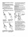
iPELIGRO!
Cuando transporte, instale, ajuste o
haga reparaciones a su m&quina lavadora a
presi6n, siempre desconecte el atambre de la bujia
y col6quelo donde no pueda entrar en contacto con
la bujia para evitar arranques accidentales._
Los gases del sistema de escape del motor contienen
gas de mon6xido de carbono MORTAL,, Si este gas
petigroso se inhala en concentraciones suficientes,
puede causar p_rdida de fa consciencia o incluso la
muerte., Opere este equipo unicamente al aire libre,
donde se encuentre disponible ventilaci6n adecuada.,
2
Hoffman
Estates,
los cuales varian
IL 60179
=
La gasolina es altamente INFLAMABLE y sus vapores
son EXPLOS1VOS. No perrnita que fumen, que existan
llamas abiertas, chispas o calor a su alrededor cuando
manipule gasolina,, Evite regar gasolina sobre un motor
caliente, Permita que la unidad se enfrie por 2 minutos
antes de volver a colocade combustible,, Cumpla con
todas las leyes que regulan et almacenamiento y el
manejo de gasolina,,
°
Coloque esta m&quina tavadora a presi6n en areas
alejadas de materiales combustibles, humos o polvo
combustibles,
=
El equipo de alta presi6n est,. disefiado para ser
utilizado unicamente con las pares autorizadas Sears,
Si utiliza este equipo con partes que no cumplan con
las especificaciones minimas, el usuario asume todos
los riesgos y responsabilidades,,
-
Algunos qu[micos o detergentes pueden ser nocivos si
se inhalan o ingieren, causando n&usea severa,
desmayos o envenenamiento., Los elementos nocivos
pueden ocasionar daSo a ]a propiedad o lesiones
severas.
=
No permita en ning_n momento que NINOS operen la
M&quina Lavadora a Presi6n,
E! escape del motor de este producto contiene
elementos qufmicos, los cuales son reconocidos
en el Estado de California por producir cdncer,
defectos de nacimiento u otros dafios de tipo
reproductivo.
iPRECAUCION!
Antes de usar este producto, lea
este manual y siga todas las Regtas de Seguridad y
tas Instrucciones de Operaci6no
puede tener otros derechos,
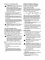
°
Opere e! motor Linicamente a la velocidad de mando.
Hacer funcionar el motor a velocidades excesivas
aumenta el peligro de lesiones personales No juegue
con partes que puedan aumentar o disminuir la
velocidad de mando..
°
Utitice un respirador o mascara siempre que exista la
posibilidad de inhalar vapores.. Lea todas las
instrucciones de la mascara para asegurarse de que le
brindarA la protecciOn necesaria contra la inha]aci6n de
vapores nocivos_
o
No use ropa suelta, joyas o elementos que puedan
quedar atrapados en el arranque u otras parfes
rotatorias.
°
,
Antes de poner en marcha la MAquina Lavadora a
Presi6n en clima frio, revise todas las partes del equipo
y asegt)rese de que no se haya formado hieloo
El rociado de alta presi6n puede da5ar elementos
frAgiles, inctuyendo el viddo. No apunte la pistola de
rociado al vidrio cuando est6 en el modo de rociado a
chorro.r
°
Mantenga conectada la manguera a la mAquina o a la
pistola de rociado cuando el sistema est_ presurizado.
Es peligroso desconectar la manguera cuando la unidad
est_ presurizada.
o
NUNCA deberAn ser operadas las unidades con partes
rotas o ausentes, o sin la caja o cubiertas de
protecci6n.
o
°
El silenciador de escape y el depurador de aire deberAn
estar instalados yen buenas condiciones antes de
operar la M&quina Lavadora a Presi6n. Estos
componentes actSan como apagachispas si el motor
presenta contrafuegos.
Sostenga firmemente en su mano la manguera de
rociado antes de poner en marcha la unidad., De no
hacerlo, podrian ocurdr lesiones por el movimiento
brusco de la pistola de rociadoo No abandone la pistola
de rociado cuando la m_quina est_ en funcionamiento..
°
Revise que el sistema de combustible no presente
fugas o signos de deterioro, como mangueras
desgastadas o porosas, sujetadores flojos o ausentes,
tapa o tanque daSados. Cordja todos los defectos antes
de operar la M_quina Lavadora a Presi6no
El Area de limpieza deberA tener inclinaciones y
drenajes adecuados para disminuir la posibilidad de
caidas debido a superficies resbalosas.
-
Mantenga el chorro del agua alejado de alambrados
el_ctricos, de 1o contrario podrfan ocurdr descargas
electricas fatales.
°
No rocie liquidos inflamables..
•
°
Nunca perrnita que partes del cuerpo entren en
contacto con la corriente del fluido.. NO entre en
contacto con la corriente del fluido creada pot una fuga
en ta mangsera de alta presi6no
No asegure el gatillo de ta pistola en la posici6n
posterior (abierto)o
•
No eluda ningun dispositivo
m_quina..
°
El silenciador y el motor se calientan durante el
funcionamiento y permanecen calientes inmediatamente
despu_s del apagado. Evite el contacto con
silenciadores o motores calientes, o podria quemarse
severamente..
°
Opere y almacene esta unidad sobre una superficie
estable°
•
La manguera de alta presi6n puede desarrollar fugas
debido al desgaste, dobleces, abuso, etc.. Et agua que
sale de una fuga es capaz de enyectar materiales en la
piel. Inspeccione la manguera siempre que la vaya a
usan Revise todas las mangueras para vet si presentan
cortes, fugas, abrasiones o deformaciOn de la cubierta,
da5o o movimiento de acoptamientos_ Si existe
cualquiera de estas condiciones, reemptace la
manguera inmediatamente
Nunca repare la manguera
de alta presi6n_ Reemplaceta con una manguera que
reuna la clasificaci6n minima de presiOn de su m_quina
lavadora a presi6n..
°
°
Las corrientes de alta presi6n que produce este equipo
pueden pefforar la piel y sus tejidos profundos,
ocasionando lesiones serias y posibie amputaci6n..
°
Nunca apunte la pistola a la gente, animales o plantas.
-
Et rociado de atta presi6n puede hacer que particulas
pequeSas de pintura u otras parti'culas salgan
disparadas y viajen a altas velocidades.
°
Siempre use protecci6n para los ojos cuando utilice
este equipo o cuando est_ cerca de donde se est_
usando el equipo..
°
Opere la presi6n a un valor que no exceda la presi6n
del fluido en PSI de su mAquina lavadora a presi6m
-
Nunca mueva la m_quina halando ta manguera de alta
presi6n.. Utilice la manija ubicada en la parte superior de
la unidad,,
-
Siernpre asegerese de que la pistola de rociado,
boquillas y accesorios est_n conectados correctamente
°
Nunca utilice una pistola de rociado que no tenga un
seguro para gatitio o protecci6n para gatitlo en su lugar
y en buenas condiciones.
de seguddad de esta
ESTE PENDIENTE
DE ESTE SIMBOLO, EL CUAL LE ADVIERTE
DE IMPORTANTES
PRECAUCIONES
DE SEGURIDAD.
SIGNIFICA "ATENCION",
iESTE ALERTA! "SU
SEGURIDAD
ESTA EN RIESGO".
3
CONTENIDO
DE LA CAJA
Las siguientes partes son enviadas sueltas con su m_quina
lavadora a presi6n:
o Unidad Principal - m&quina lavadora a presiSn con ruedas,
manija gu_ao
o Manguera de Alta Presi6n
° Caja de partes (incluye los siguiente elementos):
° Pistola de Rociaclo
COMO PREPARAR LA MAQUINA
LAVADORA A PRESION
La gran mayofia de su M_quina Lavadora de Alta Presi6n
Craftsman ha sido ensamblada en la f_brica. Sin embargo,
usted deber& ensamblar la pistola de rociado y conectar la
manguera de alta presiSn a la bombay a ]a pistola de
rociado,
o
Corte los amarres de la manguera de alta presi6n y
conecte la manguera de alta presi6n a la pistola,. Apriete
con la mano.
•
Retire la tapa pl_stJca y conecte la manguera de alta
presi6n a la bomba_ Apriete con la mano,.
° F_tensi6n para Boquillas
° Boquilla Ajustable de AttaJBaja Presi6n
° BoquiUa a Chorro
° Aceite para Motor
• Bolsa del Manual (incluye los siguientes elementos):
o Manual dei Propietario
- Juego para Umpiar Boquillas
° Juego de Ani]los 'O'
Familiarfcese con cada parte antes de ensamblar la
m_quina lavadora a presi6n. Compare el contenido con la
ilustraci6n de la P_gina 5, Si atguna de la partes no est&
presente o se encuentra daSada, flame a la L_nea de Ayuda
de la M_quina Lavadora a Presi6n al 1-800-222-3136,
COMO RETIRAR
LA MAQUINA
LAVADORA
A PRESiON DE LA CAJA
-
Retire las partes sueltas y la caja de repuestos incluida
con la m_quina lavadora a presi6n.,
°
Corte dos esquinas en el extremo de la manija gufa de
la caja de la parte superior a la inferior, de manera que
el panel pueda ser doblado hacia abajo..
o
Levante la manija guia. asegurela en su sitio y saque la
m_quina iavadora a presi6n de la cajao
La salida de aita
presi6n se
encuentra en
este lado de la
unidacl, por
debajo del
motor.
°
Conecte la extensi6n para boquillas a la pistola de
rociado alineando las salientes de aseguramiento de la
extensi6n con las ranuras de la pistola.. Empuje la
extensi6n y gfrela en sentido de tas manecillas del reloj
para asegurada en su sitioo
°
Conecte la boquiHa que desee a ia extensidn para
boquilfas..
°
Coloque la pistola de rociado ensamblada
Levante la manija a la
posici6n vertical y mueva
la tapas de fijaci6n a su
sitio.
Revise la caja para ver si existen partes sueltas
adicionates.
en el soporte.,
CONOZCA
SU MAQUINA
LAVADORA
DE ALTA
PRESION
Lea este manual del propietario y las reglas de seguridad antes de porter en maroha su m_quina lavadora de alta
presi6n. Compare las ilustraciones con su m_quina lavadora de alta presi6n para familiarizarse con las ubicaciones de los
diferentes controles y ajustes.
Manguera
de A[ta Presi6n
Pistola de Rociado
Arranque de Retroceso
Filtro y Tubo de Toma
de Detergente
Palanca de Control
del Regulador
de Aceite
Filtro de Aire
Perilla del Cebador
Tanque de Gasolina
Boquilta Ajustable
Salida de Alta PresiSn
BoquiUaa Chorro
Entrada de Agua
Bomba
Arranque de Retroceso _ Usado para dar arranque al
motor manuaimente,,
Filtro y Tubo de Toma de Detergente _Se usa para
succionar el detergente de la boteEla de quimicos a la
cordente de agua de baja presi6n,
Bomba - Desarrolla atta presi6n de agua.
Manguera de Atta Presi6n - Conecte un extremo a la
pistola de rociado y el otro a la salida de atta presi6n_
Boquilla Ajustabte - Se conecta a la extensi6n para
boquillas y ajusta la presiSn a alta o baja presi6n, rociado a
chorro o en abanico.,
Palanca de Control del Regulador - Atista et motor para
darJe arranque y detiene el motor.
Perilla del Cebador- Usada para el arranque de motores
ffios.
Boquilla a Chorro - Se conecta a la extensi6n para
boquilJas y le permite limpiar o enjuagar superficies a aita
presi6no No se puede aplicar detergente utilizando la
boquilla a chorro,
Pistola de Rociado - Controla la aplicaci6n de agua sebre
ra superficie de iimpieza con el gatillo_ lncluye cerrojo de
seguridad,
Entrada de Agua - Conecte la manguera de jardfn aquf
utilizando el conector para manguera de jardfn (no
mostrado).,
Extensidn para Boquillas
rociado y a las boquillas,,
Salida de Alta PresiSn - Conexi6n para fa manguera de
atta presi6n,
- Se conecta a la pistola de
Tanque de Gasolina - Llene e! motor con gasolina regutar
sin contenido de piomo,,
Filtro de Aire - El elemento de filtro tipo seco limita la
cantidad de suciedad y polvo que se introduce en el motor,
Tapa del Llenado de Aceite - Llene el motor con aceite
aquL Vea la Pdgina 7 para las recomendaciones del aceite.,
5
COMO USAR SU MAQUINA
PRESION
LAVADORA
A
Lea estas instrucciones y aprenda c6mo usar su m_quina
lavadora a presi6n antes de intentar dade arranque a la
mismao Si tiene problemas
operando su m&quina lavadora
a presi6n, por favor Ilame a la Ifnea de ayuda de la m&quina
lavadora a presi6n al 1,-800_222_3136.
•
Para una limpieza m_s efectiva, mantenga la boquilla de
rociado de 8 a 24 pulgadas de la superficie de limpieza,
°
Si coloca la boquilla de rociado demasiado cerca,
especialmente en el modo de aIta presi6n, podrfa daSar
la superficie de limpieza,.
Procedimiento
de Limpieza Usando la
Boquilla Ajustable
C6mo Usar la Boquilla Ajustable
_k
•
IMPORTANTE: Utiiice jabones diseSados especificamente
para m_quinas lavadoras a presi6n_ El detergente casero
podria da_ar la bombao
DVERTENCIA:
ajuste el patrSn
de tas
rociado
cuando est_Nunca
rociando_Nunoa
coloque
manos en frente de la boquilla cuandoajuste el
rociado.
Mueva la boquilla hacia adelante para ajustar el rociado
al modo de baja presi6n° Mueva la boquilla hacia atr_s
para obtener alta presi6n,
IMPORTANTE: Usted deberd conectar todas las mangueras
antes de dade arranque al motor. Arrancar e] motor sin
todas las mangueras conectadas y sin el suministro de agua
ABIERTO (ON) causar_ el daSo de la bomba,,
Para aplicar detergente siga estos pasos:
•
Prepare la soluci6n de detergente siguiendo las
instrucciones det fabdcante,,
•
Cuelgue la soluci6n de detergente en el gancho de ]a
manija.
Cuelgue la botella
del detergente en
este gancho°
\
Mueva la boquilla
hacia atr_s para
colocarla en el modo
de alta presi6n.
Mueva la boquilla hacia
adelante para colocarla
en el modo de baja
Presi6n.
AI girar la boquilla se ajusta el patr6n de rociado de un
patr6n angosto a un patr6n en "abanico"o
Gire ta boquilla en sentido
de las manecillas det reloj
para un patr6n de rociado
angostoo
Gire la boquiila en sentido
contrario alas maneciltas
del reloj para un patr6n de
rociado en "abanico".
•
Coloque el _tro pequeSo del tubo de inyecci6n de
qufmicos transparente en el recipiente del detergente,,
°
Mueva la boquilla ajustable hacia adelante al modo de
baja presi6n. Et detergente no se puede aplicar con la
boquilta en la posici6n de alta presidn.
•
Repase el uso de la boquilla ajustabte.,
°
Conecte la manguera de jardin a la entrada del agua
(vea =PUESTA EN MARCHA DE SU MAQUINA
LAVADORA DE PRES1ON" en la p&gina 8), revise que
la manguera de alta presi6n est_ conectada a la pistola
de rociado y a la bomba (vea MONTAJE en la p_gina 4)
y de arranque at motor.
o
Para la limpieza, comience en la parte inferior del _rea
que se va a lavar y dirfjase hacia arriba, utilizando
movimientos largos y superpuestos
•
Permita que el detergente penetre entre 3-5 minutos
antes de lavar y enjuagaro Vuelva a aplicar cuando sea
necesario para evitar que Easupefficie se seque_
Enjuague con la Boquilla Ajustable
,_
•
ADVERTENC1A:
Sealavadora
bastante acuidadoso
si tiene
que utilizar la m_quina
presi6n desde
una
escalera, andamio o cualquier otro fugar
relativamente inestable,, Cuando oprima el gatillo, la
fuerza de reacci6n del rociado inicial podfia hacerlo
caer, o si est_ demasiado cerca a la superficie de
limpieza, la afta presi6n podr_a hacerlo satirse del
aparato en que est_ ubicadoo
Conecte e! suministro de agua y ponga en marcha su
m_quina lavadora a presi6n (vea "PUESTA EN
MARCHA DE SU MAQUtNA LAVADORA DE PRES!ON"
en la p_gina 8).,
o
Mueva la boquilla ajustable hacia atr&s a la posici6n de
alta presi6n., Espere hasta que el detergente deje de
salir. El detergente no circular,_ cuando est_ en el modo
de alta presi6n.
=
Cuando el detergente haya dejado de salir, expanda el
patr6n de rociado para obtener una acci6n de enjuague
m_s suave. Comience por la parte superior del _,rea que
va a enjuagar, difijase hacia abajo con el mismo
movimiento usado para la limpieza..
ANTES DE PONER EN MARCHA LA
MAQUINA
LAVADORA A PRESION
Para operar el motor deber& hacer Io siguiente:
Agregue Aceite para Motor
Utitice _nicamente aceite detergente de alta calidad que
tenga una clasificaciOn de servicio API SF o SG, Seleccione
el grado de viscosidad SAE del aceite de acuerdo a la
temperatura de funcionamiento esperada..
frio
-==_.,.==
32°F
5W30
_
calinete
SAE 30
A pesar de que los aceites de muttiple viscosidad (5W30,
10W30, etc.) mejoran el arranque el climas frios, estos
aceites producen un aumento en el consumo de aceite
cuando son usados por encima de 32F._Revise el nivel de
aceite del motor con mayor frecuencia para evitar dafio
debido al funcionamiento con un bajo nivel de aceite..
°
Coloque ta m_quina lavadora a presi6n sobre una
superficie nivelada,.
•
Limpie el _rea alrededor del odficio de ilenado de aceite
y retire la variHa de medici6n de aceite._
•
Limpie la vafilla de mediciSno
o
Vierta el aceite de la botella suministrada en la apertura
para Ilenado de aceite hasta que Ilegue a la marca de
full (lleno) de la varilta de medici6n. Det_ngase y revise
el nivel de aceiteo No [lene excesivamente.
C6mo Usar ia Boqui!la a Chorro
o
La boquilla a chorro hace girar ta cordente de aita presiSn
en un patr6n circular r&pido. El rociado de alta presi6n es
m_Ssefectivo cuando la punta de la vara se encuentra entre
8 y 24 putgadas de la supefficie que se est& limpiando_.
tnstale la vadlla de medici6n de aceite y apriStela con la
mano firmemente.
Agregue Gasolina
,_k
PRECAUCION:
Haga una
en un Asegurese
_rea
pequeSa
de la supefficie
que prueba
va a limpiar_
de que no resutte dafiada por el rociado de alta
presi6n..
•
Use gasolina regular sin contenido de plomo en el motor
de la m_.quina lavadora a presi6n. La capacidad del
tanque de combustible es de 1 cuarto Amedcano.
Siempre comience a usar la boquilla a chorro a cierta
distancia y vaya acerc_ndose a la superficie gradualmente
hasta que obtenga la fuerza de limpieza que deseeo
_
,_
PRECAUCION:
La boquiIla
a chorro produce
un
rociado con una presi6n
extremadamente
alta, capaz
de remover pintura y hacer agujeros a trav_s de las
superficies si la sostiene demasiado cerca.. Siempre
asegurese de que la superficie que va a limpiar no
vaya a ser daSada por el rociado de alta presi6n
haciendo una prueba en un _rea escondida.
o caliente, No encienda cigarrillos o fume cuando
Ilene el tanque de combustible,
PRECAUCION:
No Ilene excesivamente el tanque
de combustible, Siempre deje espacio para la
expansi6n del combustibte,.
Nora: Usted no puede aplicar detergente con la boquilla a
chorro.
Para conectar la boquilla a chorro a ta pistota de rociado:
°
Retire el accesorio que est_ conectado a la extensi6n
para boquillas.
•
Conecte la boquilla a chorro a la extensi6n para
boquillas,
•
Conecte la extensi6n para boquillas a la pistola de
rociado alineando las salientes de aseguramiento det
adaptador de accesorios con las ranuras de la pistola_
Instale la boquitla y girela hasta que se asegure en su
sitio.
Nunca lleneNunca
el tanque
enELIGRO:
recintos encerrados_
ilenedeelcombustible
tanque de
combustible cuando el motor est_ en funcionamiento
,_
PRECAUCION:con mezcia
La experiencia
nos(Ilamados
indica que los
combustibles
de alcohol
gasohol o que usen etanol o metanot) pueden atraer
la humedad, la cuat Ileva a la separaci6n y formaci6n
de &cidos durante el almacenamiento. La gasotina
_cida puede da_ar el sistema del combustible de un
motor en almacenamJento
Para aSadir combustible
al motor:.
•
Limpie el firea alrededor de la tapa del combustible,
retire la tapa_
•
Agregue lentamente gasolina regular sin ¢ontenido de
plomo al tanque de combustible,
importante:
°
Nunca mezcte aceite con gasolina,.
instale la tapa del combustible
derrame de gasolina..
y limpie cualquier
PUESTA EN MARCHA DE SU MAQUiNA
LAVADORA DE PRESION
o
Coloque la m_quina favadora a presi6n en un _rea Io
suficientemente cerca a una fuente de agua externa que
pueda circular a una velocidad de por lo menos 2.2
galones pot minutoo Conecte una manguera de jardfn a
una caniIla del agua.
•
Revise que la manguera de alta presi6n est_ firmemente
conectada a la pistola de rociado y a la bombao Vea la
secci6n de MONTAJE en la p&gina 4 para las
ilustraciones,.
o
Revise et colador de entrada de la entrada de aguao Si et
colador est& sucio, timpielo antes de conectar la
manguera de jardin_ Si el colador est& dafiado, no Io
conecte a la manguera de jardfn_ Reemplacelo con el
colador suministrado en el juego de mantenimiento o
Ilame al 1-800-366-PART para ordenar un colador de
repuesto.
o
Conecte la manguera de jardfn a la entrada del agua_
°
Abra el suministro
o
Opdma (5) veces la perilla del cebador firmemente°
o
Agarre la manija de la soga y h&ieta lentamente basra
que sienta cierta resistencia.. Despu_s hale la cuerda
r_ipidamente para superar la compresi6n, evitar el
contragolpe y dar arranque al motor. Permita que la soga
regrese lentamente al arranque_
Nota, Siempre conserve la Palanca de Control det
Regulador en la posici6n 'Fast' (R_pido) cuando opere la
m&quina lavadora a presi6no
Para darle Arranque al Motor a Partir de ese
Momento:
•
Asegtirese de que el control del regutador del motor se
encuentre en la posici6n "Fast".
°
Oprima 3 veces la perilla del cebadoro Para motores
calientes, no use el cebador.
•
Agarre la manija de la soga y h_lela lentamente hasta
que sienta cierta resistencia,. Despu_s hale la cuerda
r_pidamente para superar la compresiSn, evitar el
contragolpe y dar arranque al motor. Perrnita que la soga
regrese lentamente al arranqueo
•
Si el motor no arranca, hale el gatillo de la pistola hasta
obtener una corriente de agua constante, optima la
perilla del cebador tres veces m_s y hale del arrancador_.
del agua.
importante: No haga funcionar la bomba sin que el
suministro de agua est_ conectado y abierto,. Deber& seguir
esta precauci6n o la bomba resultar& daSada.
Purgue el aire de la bomba:
o
Conecte la boquil}a que clesee a la extensi6n para
boquillas.
o
Retire la extensi6n para boquillas de la pistola de
rociado.,
°
Hale el gatillo de la pistota de rociado y mant_ngalo
oprimido hasta que obtenga una corriente de agua
constante.
Enganche el cerrojo de seguridad
rociado,.
de la pistola de
Nota: Siempre mantenga la Palanca de Control del
Regulador en ]a posici6n "Fast" cuando est_ usando la
m_quina lavadora a presi6no
COMO DETENER SU MAQUINA
LAVADORA
A PRESION
°
Mueva la palanca de control del regulador a la posiciSn
'Slow' ('Lento'),,
•
Espere que el motor vaya a marcha en vac_oo
=
Mueva la palanca de control det regulador a la posici6n
'Stop' ('Parado'),
•
El simple apagado del motor no elimina la presi6n del
sistema. Apriete el gatillo de la pistola de rociado
para eliminar ta presi6n de la manguera,
Nota: Una pequeSa cantidad de agua saldrd de ]a pistola de
rociado cuando elimine la presidn.
USO DEL SIFON
°
Conecte la extensiSn para boquillas a la pistola de
rociado.,
Para darle arranque al motor por primera vez:
°
Mueva la palanca de control del regulador a ta posici6n
"Fast" (R_ipido).
R_pido
Lento
Parado
Le recomendamos que NO utitice agua estancada como
suministro de agua_ El agua sucia, contaminada o salobre
puede dafiar fa bombao Con_ctela L_nicamente al suministro
de agua de su casa,.
SUGERENCIAS
•
Nunca use ia entrada de la manguera de jardfn para
sifonear detergente o cera.
•
Si tiene la boquilia de rociado demasiado lejos, la
limpieza no set& tan efectiva_
RESPONSABILIDADES
HORARiO
DEL CLIENTE
DE MANTENIMiENTO
INTERVALO DE OPERACION PeR
LLENE CON FECHAS A MEDIDA QUE VA
COMPLETANDO
EL SERV[CEO REGULAR
Antesde
cadause
TAREA DE MANTENIMIENTO
MAQUINA
LAVADORA
FECHAS DE SERVICIO
HeRA
Cada25
Horaso
Anualmente
Cada t00
Horaso
Anuatmenle
A PRESION
Revlsar,
qimpiarelcoladorde la entrada
de aguade facenexidnr_pida.
Xl"
Revisarla manguerade alta presi6n.
X
Revisarta manguerade detergente.
X
.....
Revisar_apistola de roeiadoy e_conjun_o
paraversi existenfugas.
X
PurgarIabombade airey conlaminantes.
X
_.._
j
.....
I
L
I
MOTOR
Revisar el nivel de aceite
X
Cambiarelaceitede{motor.
X"
Oar servicio al depurador
X*"
,,,
j,,j
,,,,
,
de aire.
Limpiar t reemplazar la bujfa,
X
Preparar para afmacenamiento.
_...
t
""
Prepare ta unidad para almacenamiento
si va
a estar fuera de servicio per m,_s de 3.0 dl,aS_
. .i ............
Limpiar si est_ obstruido Reemplazar si est_ perforado o rote.
Cambiar ei aceite despu_.s de las pdmeras (5) betas y despu_s cada 25 horas_ Hacer el cambio de aceite con mayor frecuencia
condiciones de mucha suciedad o polvo..
Reemplazar m_s a menudo bajo condiciones de suciedad o pelvo..
PRODUCT
SPECIFICATIONS
En et estado de California es obligatorio, seg_Jn la ley, el use
de apagachispas (Secci6n 4442 del C6digo de Recursos
Pt_blicos de CaJifomia).. Otros estados pueden tenor leyes
simitares. Las 1eyes federales se aptican en tierras
federales.
Pressure Washer Specifications
PRESTON..............................................
VELOCIDAD
MEZCLA
1500
2 G PM
DE: FLUJO ....................................
DE DETERGENTE
............
U_ilice deteraente
sin dituir.
TEMPERATURA DEL
SUMINISTRO DE AGUA ............ Que no exceda los !40F
Nota: Si equipa el motor de su m&quina lavadora a presiSn
con un silenciador apagachispas, el apagachispas deber_.
ser mantenido en condiciones de trabajo efectivas per et
operador / propietado.
Listed puede ordenar el apagachispas (P/N 398067) a
tray,s de su Centre de Servicio Sears_
RECOMENDACIONES
Engine Specifications
MODELO DEL MOTOR ......................
Brklcls& Stratton
CABALLOS DE FUERZA .....................................
BUJIA: Tipo: .............................
..............
3.75
GENERALES
La garanUa de la m_.quina lavadora de alta presiSn no cubre
los elementos que han side sujetos a abuse o negligencia
per parte del operador. Para recibir el valor total de ta
garant_a, el operador deber& mantener la m&quina lavadora
de alta presiSn come se indica en este manual.
Champion RJ-19LMo
equivalente..Calibre ta
Separaci6n a:0.030 puF
AIgunos ajustes tendr_n que hacerse periSdicamente para
mantener adecuadamente su m_.quina lavadora de aJta
presi6n..
nadas _6mm._
Todos Ios ajustes de la secci6n de Servicio y Ajustes de
este manual deber_n hacerse per Io menos una vez en
cada estaci6n.
CAPACIDAD DE LA GASOLINA .... 1.0 cuartos Americanos
ACEITE ...............................................
cuando trabaje en
Peso SAE 30
SEPARAClON DE AIRE DEL .......... 0 006 - 0.010 pulgadas
ENCENDIDO DE ESTADO SOLIDO
Una vez al a5o, usted deber_ limpiar o reemplazar la
bujfa, reemplazar el filtro de aire, revisar si la extensi6n
para boquillas y las boquillas est_.n desgastadas_ Una
buj_a limpia y un fittro de aire nuevo garantizan una
mezcla de combustibte-aire adecuada y le ayuda a su
motor a funcionar mejor y a toner una vida _til m&s
prolongadao
ANTES
•
DE CADA
USO
•
Ponga en marcha el motor de acuerdo a las
instrucciones de la secci6n OPERACION, pAgina 5,
Revise si existen dafios en el cotador de la entrada de
aguao
•
Hale el gatillo de la pistola y mant_ngato
•
Revise si existen fugas en la manguera de alta presi6n,
=
°
Revise si existen daRos en el filtro y manguera de
entrada del detergente,
Cuando el suministro de agua sea uniforme y constante,
enganche et cerrojo de seguridad y vuelva a instalar la
conexi6n para boquillas,,
o
Revise si existen fugas en la pistola o boquilla&
Mantenimiento
°
Purgue la bomba de aire y contaminantes,.
°
Revise e! nivel de aceite del motor,
Si la boquilla se obstruye o tapa con matedales extrafios,
como suciedad, se puede presentar presi6n excesiva de la
bomba,, Una boquilla parcialmente tapada puede causar una
sensaci6n pulsatil durante el usoo Esto generalmente no es
un problema relacionado con la bomba, es m&s que todo
una boquilla tapada o parcialmente obstruida,
MANTENIMIENTO
DE LA MAQUINA
LAVADORA
A PRESION
apretado._
de las Boquillas
Si la boquilla se tapa u obstruye parcialmente, limpieia
inmediatamente con el juego suministrado con su m&quina
lavadora a presi6n siguiendo estas instrucciones:
Revise y Limpie el Colador de Entrada
Examine el colador de entrada.. Limpielo si est_ tapado o
reempl_celo si est& roto.,
°
Apague el motor y cierre el suministro
Revise la Manguera de Alta Presi6n
°
Separe la extensi6n para boquillas de ]a pistol&
La manguera de afta presi6n puede desarrollar fugas por el
desgaste, dobleces o abuso.. Revise la manguera antes de
cada uso. Revise si existen cortes, fugas, abrasiones,
levantamiento de ta cubierta, daBo o movimiento de los
acoplamientoso Si existe cualquiera de estas condiciones,
reemplace la manguera inmediatamente_
•
G[rela a Ia posici6n de corriente,,
°
Retire la boquilla del extremo de la vara usando la Ilave
allen incluida en el juego o una Ilave allen de 2 mm o
5/64.,
o
Use el alambre incluido en el juego o un clip de papel
pequeSo para liberar los materiales extraSos que est_n
tapando u obstpJyendo la boquilta..
,_
PELIGRO:Reemplacela
Nunca repare
la manguera
alta
presi6no
con una
mangueradeque
cumpla con |a capacidad m_nima de presi6n de su
mdquina lavadora a presi6n..
Revise la Manguera del Detergente
de agua,,
Examine el fiItro de la manguera de detergente y Iimpielo si
est& tapado. La manguera deberd adaptarse con precisi6n
en el ajuste.. Revise si la manguera presenta fugas o
pJpturao Reemplace el filtro o la manguera si alguno de eltes
estd daSado..
lntroduzca
el alambre dentro de ta boquitla y gi'relo
hacia los lados, hacia adelante y atr_s hasta despejar
obstrucci6n.
Revise la Pistola y la Vara
Examine la conexi6n de la manguera a ta pistola y
cerci6rese de que est6 asegurad& Pruebe el gatillo
opdmi_ndolo y asegur_ndose de que regresa a su sitio
cuando lo suelte. Coloque el cerrojo de seguridad en la
posiciSn UP (ARRIBA) y pruebe el gati]lo, Usted no deber_
ser capaz de oprimir el gatillo, Reemplace la pistola si faila
en cuatquiera de estas pruebas.
la
Retire la suciedad adicional inyectando el suministro de
agua en sentido contrario a tray,s de la vara.. Lave de
esta forma de 30 a 60 segundos Gire la vara al rociado
de chorro y mueva la boquilla de presi6n baja a atta
mientras hace et lavado_
Purgue la Bomba de Aire y Contaminantes
Para retirar e! aire de la bomba, siga los siguientes pesos:
•
Instale |a m_quina lavadora a presi6n come est#, descr_to
en la secci6n de MONTAJE, pagina 4, y conecte el
suministro de aguao
=
Retire la extensi6n para boquillas de la pistola.
°
Hate el gatillo de la pistola y mant6ngalo apretado hasta
que obtenga una corriente constante
Para retirar los contaminantes
siguientes pasos:
Vuelva a instalar la boquilla en la varao NO la apriete
demasiadeo
Vuelva a conectar la extensi6n de la vara a la pistola de
rociado.
de la bomba, siga los
°
Instale la m&quina lavadora a presi6n como est_ descdto
en la secci6n de MONTAJE y conecte el suministro de
agua.
°
Retire la conexi6n para boquillas de la pistola.
VueIva a conectar el suministro de agua, ABRA el
suministro agua y dele arranque al motor..
o
10
Pruebe la m_quina lavadora a presi6n haci_ndola
funcionar con la boquilla en las posiciones de alta y baja
presi6n,
MANTENIMIENTO
DE LOS ANILLOS
'O'
-
Ani!lo 'O', verde claro, (99794) para las conexiones de
accesorios machos,
o
Anillo 'O', rojo, (B2726) para la conexi6n de la extensi6n
para boquitias,.
Durante }a operaci6n normal de su m_tquina lavadora a
presi6n, los Anitlos 'O', los cuales mantienen apretadas y
fibres de fugas las conexiones de las mangueras y la
pistola, pueden desgastarse o daSarse_ Su m_quina
lavadora a presi6n vJene con un Juego de Mantenimiento
para Anillos 'O', el cual proporciona Anitlos 'O', Arandela de
Caucho y colador para fa entrada de agua de repuestoo
Las partes del Juego de Anillos 'O' incluyen:
•
Anillos 'O', amadllos, (p/n B2264) para los extremos de
la manguera de alta presi6no
°
1 arandela de caucho (p/n B2385) para la parte intema
del conector de la manguera de jardin..
°
1 colador para ta entrada de agua (pin B2384) para et
conector de la manguera de jard_n..
Para retirar un Anillo 'O' desgastado o
dafiado:
•
11
Utilice un destomillador de cabeza plana pequefio,
co!6quelo pot debajo del anillo 'O' y s_quelo haciendo
palanca..
MANTENIMIENTO
DEL MOTOR
Retire el tomillo de la cubierta del depurador
de aireo
Revisi6n del Nivel de Aceite
El nivel de aceite deber_, revisarse antes de cada uso o por
Tomenos cada (5) horas de operaci6n° Conserve el nivel de
aceite adecuado.
rrtillo
caia"
Cambio
de Aceite
ARME EL ELEMENTO DE
MANERA QUE EL REBORDE
SOBREPASE EL BORDE DE
LA CAJA DEL DEPURADOR
DE AIRE.
EL REBORDE FORMARA UN
SELLO PROTECTOR
CUANDO LA CUBIERTA SEA
ARMADA,,
Cambie el aceitedel motor despu6s de las primeras (5)
horas y cada25 horas a partirde ese momento.. Si est&
utilizando su m&quina lavadoraa presi6n bajo condiciones
de extremasuciedado polvo,o en un clima demasiado
caliente, hagael cambio de aceite m_s frecuentemente.
Cambie el aceitecuando el motortodavia se encuentre
calientedespu6s de! funcionamiento, como se indicaa
continuaciSn:
•
•
Drene el tanque de combustible haciendo funcionar la
m_quina lavadora a presi6n hasta que el tanque de
combustible est6 vacioo
Reborde
o
Retire cuidadosamente el depurador de aire sucio para
evitar que suciedad caiga dentro del carburador..
o
Desarme el depurador y limpie todas las partes_
Para dar servicio al elemento de espuma, I_velo en
detergente ffquido y agua. Espfimalo hasta secado en un
trapo limpio. SatOrelo con aceite para motor limpio..
Espfimalo en el trapo limpio para eliminar el exceso de
aceiteo Reemplace el elemento de espuma si est_ muy
sucio o dafiado..
Limpie et &rea alrededor del ilenado de aceite, retire la
tapa del llenado de aceite/varilla de mediciSn.. Limpie la
varilla de medici6n_
Incline su m_quina lavadora a presi6n para drenar
completamente el aceite a trav6s det tubo de Ilenado en
un recipiente adecuado, asegur_ndose de inclinar su
unidad en direcci6n contrafia a la bujia_ Cuando la caja
del cigOefial est6 vacfa, vuelva a colocar ta m&quina
lavadora a presi6n en la posici6n vertical..
°
Vuelva a ensamblar todas las partes y apdetelas
flrmemente al carburador con el tomillo..
Limpie / Reemplace la Bujfa
Limpie o cambie la buj_a cada 100 horas de operaci6n o una
vez al aSoo
BUJ
_
Desconecte
el alambre de la buj_a
y RECAUCION:
mant_ngalo alejado
de la misma.,
o
Limpie el &rea alrededor de la buj_ao
o
Retire y revise la bujfa.
o
Cambie la bujfa si los electrodos est&n picados,
quemados o si la porcelana est& rota_ Para su
reemplazo, Linicamente utilice Champion RJ-19LM..
=
Revise la separaci6n del etectrodo con un calibrador de
alambre y ajuste la separaci6n a 0..030" si es necesario.
•
Instale ta buj_a y aprietela firmemente..
Llene la caja del cigQefial del motor con el aceite
recomendado hasta que el nivel de aceite est6 en la
marca de FULL (LLENO) de la vadl/a de medici6n, No
llene por encima de esa marca.. VIERTA EL ACEITE
LENTAMENTE.
Cuando la caja del cig_efial del motor est6 llena a su
nivel adecuado, instale y apriete la tapa!vadlla de
medici6n de aceite..
Servicio del Depurador
de Aire
Carburador
Su motor no funcionar& adecuadamente y puede dafiarse si
usted 1ohace funcionar con un depurador de aire sucio..
Si usted cree que su carburador necesita ajuste, visite su
Centro de Servicio Sears m_s cercano_ El funcionamiento
del motor no deber_ resuttar afectado a altitudes de hasta
700 pies. Para operaciones a elevaciones mayores,
p6ngase en contacto con el Centro de Servicio Sears m_s
cercano.
Limpie el depurador de aire cada (25) horas de operaci6n o
una vez al afio, io que suceda primero.. Lfmpielo m_s
frecuentemente si ta unidad funciona bajo condiciones de
mucha suciedad o polvo. Los repuestos est&n disponibles
en su Centro de Servicio Autodzado Sears local
Para timpiar el depurador de aire, siga los siguientes pasos:
i2
ALMACENAMIENTO
Nora: Como siempre, prepare la bomba de la m&quina
lavadora a presi6n come io haria despu_s de cada uso.,
DESPUES DE CADA USO
Es importante evitar la formaci6n de dep6sitos de goma en
las partes esenciales del sistema del combustible tales como
el carburador, filtro del cembustible, manguera o tanque del
combustible durante el almacenamiento, Tambi_n, la
experiencia indica que les combustibles con mezclas de
alcohol (llamados gasohol, etanol o metanol) pueden atraer
la humedad, 1o que ileva a ]a separaci6n y fermaci6n de
_,cidos durante el almacenamiento. La gasolina _cida puede
da6ar el sistema del combustible de un motor durante el
almacenamiento..
No deber_ haber agua en la unidad por largos periodos de
tiempo. Los sedimentos de minerales se pueden depositar
en partes de la bombay "congelar" su funcionamiento. Lleve
a cabo estos procedimientos despu_s de cada uso:
=
Lave la manguera del detergente colocando el fi]tro del
inyector en un balde de agua limpia mientras hace
funcienar la M&quina Lavadora a Presi6n con la boquil]a
en el medo de baja presi0n, Lave hasta que usted vea
agua clara corriendo a trav6s del tubo.
•
Apague el motor y d_jelo enfriar, despu_s retire todas las
mangueraso
Proteja el Sistema de Combustible
,_
,_
o
PRECAUCION: est_
Asegurese
de que "Step"
la Palanca
de
MarchaJParado
en la posici6n
("Parado")
antes de continuaro Puede da6ar la bomba si pone en
marcha el metor sin el suministro de agua conectado
adecuadamente_.
Saque todos los liquidos de la bemba halando la manija
de retroceso aproximadamente 6 veces con la palanca
de MarchaJParado en la posici6n "Stop" (Parado).. Esto
deber_, evacuar la mayor_a del liquido de la bomba..
•
Enrotle la manguera de alta presi6n y revisela para vet si
presenta da6oso Los certes en la manguera o et
desgaste de la misma pueden ocasionar fugas y p_rdida
de presi6n. Si encuentra atgun da6o, reemplace la
manguera.. NO intente reparar una manguera dafada..
Reemplace la manguera cen una parte Craftsman
genuina.
-
Drene el agua de la manguera y cuelguela
adecuadamente en et soporte de alambre suministrado
con la manija guia.
°
Retire toda la gasolina del tanque de combustible para
evitar que se formen dep6sitos de gema en estas partes
y causen posible real funcionamiento del motor,.
o
Aceite el Didmetro Interior del Cilindro
Retire la bujia y vierta aproximadamente 1 onza (30 ml)
de aceite para rooter dentro del cilindro. Cubra el orificio
de la buj_a con un trapo. Haga girar el motor lentamente
para distribuir el aceite..
PRECAUCION:
Evite el rociado del odficio de la
bujia cuando est_ girando el motor lentamente..
•
EN INVIERNO
Para proteger la unidad de las temperaturas de
congelamiento:
Deposite anticongelante RV (anticongelante sin alcohol)
en ta bomba vertiendo el liquido en un pedazo de
manguera de jardin de 3 pies conectado al adaptador de
entrada y halando la manija de retroceso des veces..
ALMACENAMIENTO
tnstale la bujia,. No conecte el alambre de ia bujfa.
OTROS
PRECAUCION:
Usted deber_ proteger su unidad
de las temperaturas de congelamiento. Si no te hace,
dar3ar_,permanentemente la bombay la unidad no
podr& funcionar..
o
de Aceite
Con el motor todavia caliente, drene el aceite de la caja del
cig_e6aL Vuelva a Ilenado con el grado de aceite
recomendado,, (Vea Cambio de Aceite en la P&gina 12),.
PELIGRO: en
Nunca
almacene
el metorcerrados
con
combustible
el tanque
en recintos
o en
_reas encerradas con poca ventilaci6n donde los
vapores puedan alcanzar llamas abiertas, chispas o
luces de piletos..
ALMACENAMIENTO
Haga funcionar et motor hasta que se detenga por ta
falta de combustible. AsegSrese que el suministro de
agua a la entrada de ia bomba est*_ conectado y
ABIERTO (ON).
Cambio
Almac_nela en un _.rea limpia y seca,
,_
PELIGRO: adecuado,
Drene et lejos
combustible
dentro
de un
recipiente
de llamas
abiertas
yen
lugares at aire libre, Asegurese de que el metor est_
frio, No fume..
.
No almacene
°
Reemplace su caneca de gasolina si comienza a
oxidarse,, El 6xido y/o la suciedad en la gasolina le
causar_, problemas_
gasolina de una estaci6n a otra.
•
Si es posible, almacene su unidad en un recinto cerrado
y cSbrala para protegerla del polvo y la suciedad.
ASEGURESE DE VACIAR EL TANQUE DEL
COMBUSTIBLE,
°
Cubra su unidad cen una cubierta de pretecci6n
adecuada que no retenga la humedad.
IMPORTANTE:
NUNCA cubra su m_quina lavadora a
presi6n cuande el motor y el _rea del escape est_n
calientes..
PROLONGADO
Si usted ne planea usar la M_.quina Lavadora a PresiOn por
m&s de 30 dias, deber& preparar el motor para un
almacenamiento prolongado.
13
PROBLEMA
La bomba presenta los
siguientes problemas: no
produce presi6n o produce un_
presi6n errada, traqueteo,
p_rdida de presi6n, bajo
volumen de agua.
CAUSA
SOLUCION
io La boquilla est_ en el modo de baja
presi6n_
2o La entrada de agua est_ bloqueada.
3, Suministro de agua inadecuado,
1. Mueva la boquilla hacia atr_s para el
modo de alta presi6no
2o Limpie la entrada.
3o Proporcione flujo de agua adecuado de
por Io menos 2 gpm.
4. Estire la manguera de entrada, coloque
un parche en ]a fugao
5,, Reemplace / timpie el colador de la
entrada de agua,,
6oProporcione suministro de agua m_s
fria,,
7o Retire las obstrdcciones de la
manguera de salida.
8. Reempface la manguera de salida si
presenta fugas.,
g., Reemplace el anillo 'o' o la pistola si es
necesario,,
10, Limpie la boquilla,,
11, P6ngase en contacto con el
Departamento de Servicio Sears,
4,, La manguera de entrada est,. doblada o
presenta fugas_
5,, El colador de entrada de agua est&
tapado_
6., El suministro de agua est_ por encima
de los 140F,,
7_ La manguera de salida est_ bloqueada.
8o La manguera de salida presenta fugas._
9., La pistola presenta fugas,,
10. La boquitta est_ obstruida.
11. Bomba defectuosa.,
El detergente no se mezclao
1. La tinea del detergente no est,.
sumergida en el rociado del detergente,,
2. El filtro det qufmico est& tapado,
3. La boquilla est_ en el modo de alta
presi6n.
1., introduzca la linea de qufmicos en el
detergente,
2. Umpie o reempface el filtro/linea de
detergente,
3_ Mueva la boquilla hacia adelante para
elmodo de baja presi6n.
El motor funciona bien cuando
no se est_ rociando, pero se
apaga cuando comienza a
rociar,.
La velocidad
lenta,,
P6ngase en contacto con el Departamento
de Servicio Sears,
El motor no arranca; o arranca
y funciona real
1. Depurador de aire sucio
del motor es demasiado
2o Sin gasolina.,
3,, Gasolina vieja,
4,, E1 alambre de la bujia no est_
conectado.
5., Bujfa mala,
6. Agua en la gasolina.
7,. Estrangulaci6n
excesiva o inundado,,
& Mezcla de combustible
demasiado ricao
9., V_.fvula de entrada trabada en ta
posici6n abierta o cerrada.
!O, El motor ha perdido compresi6n.
1. Limpie o reemplace el depurador de
aire,
2o Llene el tanque de combustibles,
3. Drene el tanque de gasolina; ll_nelo con
combustible fresco,
4,, Conecte el alambre a la buj_ao
5,, Reemplace la bujia,,
6. Drene el tanque de gasolina; II_nelo con
combustible fresco,,
7o Coloque la palanca de control de la
v&lvula de regulaci6n del motor en la
posici6n r_pida, cebador en la posici6n de
marcha,,
8. POngase en contacto con el
Departamento de Servicio Sears,,
9, P6ngase en contacto con el
Departamento de Ser¢icio Sears°
t0. P6ngase en contacto con el
Departamento de Servicio Sears.,
EI motor se apaga durante la
operaci6n,,
1,.Sin gasolina.
2, Filtro de aire sucio.
1. Llene et tanque de combustible.,
2, Reemplace el filtro de aire.
E1motor no tiene fuerza.,
Filtro de aire sucio,
Reemplace
14
et filtro de aireo
Pa la Lista de Partes,
\Jea el Manual en in Ids,
/5
Para la Lista de Partes,
_Jeael Manual en in Ids.
/6
Para la Lista de Partes,
Vea el Manual en in I_s,
17
P
I Lista
P rtes_
Vea el Manual en in I" ,
18
la Lista de Partes,
Vea el M ual en inglds,
19
P
la Lista de Partes,
Vea el Manual en in Ids.
2O
P
Lista de Partes,
Vea el Manual en in I_s,
21
I Lista de P rtes,
Vea el Manual en in I_s,
22.
Para la Lista de Partes,
Vea el Manual en in Idso
23
Para la Lista de Partes,
Vea el Manual en in ldso
24
Pa la Lista de Partes,
Vea el Manual en in Ids.
25
Para la Lista de Partes,
Vea el Manual en in I_s,
26
Pa I Lista de Partes,
Vea el Manual en in I_s,
27
Su sistema de control de emisiones incluye partes
como el carburador, depurador de aire, sisterna de
encendido, silenciador y convertidor catalffico,.
Tambi6n podrian estar incluidos conectores y otras
partes relacionadas con las emisioneso Donde exista
cualquier condici6n en que se pueda aplicar la
garant[a, B&S reparar_ su motor ULGE sin costo
alguno para usted, incluyendo diagn6stico, partes y
mano de obra.
Briggs & Stratton Corporation
(B&S), la
Junta Directiva de Recursos del Aire de
California (CARB) y ia Agencia de
Protecci6n Ambiental de los Estados
Unidos (U.S. EPA) - Sistema de Control
de Emisiones, Declaraci6n
de Garanffa
(Derechos y Obligaciones del Propietario
de la Garanffa por Defectos)
Cubrimiento de la Garanffa de Briggs and
Stratton Contra Defectos en el Control de
Emisiones
Para proteger el medio ambiente, los motores Briggs
& Stratton que cumplan con los estrictos requisitos de
emisiSn estar_n marcados con la siguiente leyenda
=Este motor cumple con las Leyes de Control de
Emisiones de California de 1995-'1998 para motores
ULGE y las leyes de U..SoEPA Fase 1 para motores
pequeSos para uso fuera de carreteras"o EL
CUBRIMIENTO DE LA GARANTIA DEL CONTROL
DE EMISIONES ES APLICABLE UNICAMENTE A
MOTORES CERTIFICADOS COMPRADOS EN
CALIFORNIA A PARTIR DE 1995, QUE SEAN
USADOS EN CALIFORNIA Y A MOTORES
CERTIFICADOS AI_IO 1997 Y MODELOS
POSTERIORES QUE SEAN COMPRADOS Y
USADOS EN CUALQUIER PARTE DEL TERRITORIO
DE LOS ESTADOS UNIDOS.
Los motores ULGE tienen garantfa en las partes
relacionadas con el control de emisiones por un
periodo de dos aSos, sujetos a las disposiciones
establecidas m_s adetante. Si cuatquier parte de su
motor, cubierta por la garanffa, es defectuosa, la parte
ser#. reparada y reemplazada por B&So
Responsabilidades
de Garanffa
Propietario
Como propietado de un motor ULGE, usted es
responsable por el cumplimiento del mantenimiento
exigido, el cual se encuentra listado en su Manual det
Operador/Propietario.
B&S recomienda que conserve
todos los recibos relacionados con el mantenimiento
Declaraci6n de la Garantfa Contra
Defectos
del Control
de Emisiones
dei
en
de su motor ULGE; sin embargo, B&S no puede negar
taf garantfa por la sola ausencia de dichos recibos o
porque usted no se haya asegurado de que el
mantenimiento programado haya sido Ilevado a cabo.
Como propietado de un motor ULGE, debe saber que
B&S podfia negade cubrimiento de garantia si su
motor ULGE, o una parte, ha fallado debido a abuso,
negligencia, mantenimiento incorrecto o
modificaciones no aprobadas.
Usted es responsable de presentar su motor ULGE a
un Distribuidor de Servicio Autorizado B&S tan pronto
como el problema aparezcao Las reparaciones de
garanffa sin disputa deber&n ser terminadas en un
perfodo de tiempo razonable sin exceder 30 dias,,
Si tiene preguntas con respecto a sus derechos y
responsabilidades de garantfa, deber_ ponerse en
contacto con un Representante de Servicio B&S
llamando al 1-414-259-5262.
California y los Estados Unidos
CARB, UoSoEPA y B&S est_n complacidos de
explicarles la DeclaraciSn de la Garant/a Contra
Defectos del Control de Emisiones de su equipo de
jardfn, c6sped o servicio (ULGE) a[3o 1996 o posterior..
En California, los motores ULGE nuevos producidos
en o despu6s del 1 de agosto de 1995, deber_n estar
diseSados, construidos y equipados para cumplir con
los exigentes est#,ndares anti-smog del Estada, Los
motores nuevos de encendido por chispa para uso
fuera de carreteras certificados para modelos a_o
1997 y postedores, usados en las otras partes del
territorio de los Estados Unidos, deber#.n cumptir
est_ndares similares establecidos por L.LS. EPA,. B&S
deber& garantizar el sistema de control de emisiones
de su motor por los perfodos de tiempo listados mAs
adelante, con tal de que no haya existido abuso,
descuido o mantenimiento incorrecto de su motor
ULGEo
28
La garantia de emisiones es una garantfa contra
defectos. Los defectos son considerados como tales
bajo condiciones de funcionamiento normal La
garantfa no es relacionada con pruebas de emisiones
durante el uso.
3.
La reparaci6n o el reemplazo de cualquier Parte
Garantizada ser_ Ilevada a cabo sin cargo atguno
para el propietario, incluyendo trabajo de
diagn6stico que lleve a la conclusi6n de que una
Parte Garantizada es defectuosa, con tal de que
el trabajo de diagn6stico sea realizado en un
Distribuidor de Sewicio Autodzado B&S. Para
Disposiciones
de la Garantfa contra
Defectos del Control de Emisiones de
Briggs and Stratton
servicio de garantfa relacionado con el sistema de
emisiones, p6ngase en contacto con su
Distribuidor Autorizado B&S listado en tas
"P#.ginas Amadllas" bajo "Motores, Gasolina",
"Motores a Gasolina", "Segadoras de C6sped" o
cualquier categorfa similar.
Las siguientes son las disposiciones especificas
relacionadas con su Cubrimiento de Garantfa contra
Defectos de! Control de Emisione& Esta es adicional
a la garantfa det motor B&S para motores no
regutados, la cual se encuentra en el Manual del
Operador / Propietado.
4,. Reclamos y Exclusiones del Cubrimiento
1o Partes Garantizadas
Los reclamos de garantfa deber_n ser
presentados de acuerdo a las disposiciones
Polftica de Garantfa det Motor B&S. El
El cubdmiento bajo esta garantfa se extiende
unicamente a la partes tistadas a continuaci6n
(las partes del sistema de control de emisiones) e
incluye aquelIas parte que estaban presentes en
el motor comprado.
a.
o Sistema de mejoramiento para arranque en
fifo (cebador blando)
B&So B&S no es responsable de cubrir fatlas de
Partes Garantizadas causadas pot e! uso de
partes modificadas, partes que no sean odginales
o adicioneso
y partes internas
° Bomba def Combustible
b.
5o Mantenimiento
Sistema de Inducci6n de Aire
Cuatquier Parte Garantizada que no est6
programada para reemplazo, segun Io requerido
por el programa de mantenimiento, o que est_
programada tJnicamente para inspecci6n regular
bajo la condici6n de "repare o reemplace cuando
sea necesario", ser_ garantizada contra defectos
por et perfodo de la garantfa Cualquier Parte
Garantizada que est_ programada para
reemplazo, segun 1o requerido por el programa de
mantenimiento, serA garantizada contra defectos
unicamente por el perfodo de tiempo hasta et
primer reemplazo programado de dicha parteo
Cualquier parle de reemplazo que sea equivalente
en cuanto a funcionamiento y durabilidad puede
ser usada en cuatquier mantenimiento o
reparaci6no Et propietario es responsable de Ilevar
a cabo todo el mantenimiento requerido, segun la
definici6n det Manual del Operador / Propietario
de B&So
o Depurador de aire
o MfJltiple de admisi6n
O,,
Sistema de Encendido
° Bujfas
o Sistema de encendido por magneto
d_
Sistema catatizador
• Convertidor
catalffico
• Multiple de Escape
° Sistema de inyecci6n de aire o v,_Ivula de
pulsaci6n
84
Elementos MiscelAneos Usados en los
Sistemas Anteriores
° Vacio, temperatura, posici6n, tiempo,
vAlvulas sensitivas e interruptores
o Conectores y Conjuntos
2_
de la
cubfimiento de la garantfa ser_ excluido para
fallas de Partes Garantizadas que no sean partes
originales B&S o cuando haya existido abuso,
negligencia o mantenimiento incorrecto, como es
estabtecido en la Pol[tica de Garantfa del Motor
Sistema de Medici6n de Combustible
o Carburador
No Cargos
Duraci6n del Cubdmiento
6, Cubrimiento Consecuencial
B&S garantiza al propietado inicial y a cada
comprador subsecuente que ias Partes
Garantizadas estar&n libres de defectos en
mater!ales y mano de obra que hayan causado la
falla de tas Partes Garantizadas por un per[odo de
dos aSos a partir de la fecha en que el motor es
entregado al comprador al detaL
El cubrimiento bajo esta c!_,usula ser_, extendido a
la fa!la de cualquier componente del motor
causada por la falla de cualquier Parte
Garantizada que todavfa se encuentre bajo
garantfa.
29
For in-home major brand repair service:
Call 24 hours a day, 7 days a week
1=800=4=NIY=HOME" (1-800-469-4663)
Para pedir servicio de reparaci6n a domicilio-
1-800-676-5811
In Canada for all your service and parts needs call
=- 1-800-665-4455
Au Canada pour tout le service ou les pi_ces
For the repair or replacement parts you need:
Call 7 am - 7 pm, 7 days a week
1-800-366=PART
(1-800-366-7278)
Para ordenar piezas con entrega a domicilio = 1-800-659-7084
For the location of a Sears Parts and Repair Center in your area:
Call 24 hoursa day, 7 days a week
1=800=488..1222
For information on purchasing a Sears Maintenance Agreement
or to inquire about an existing Agreement:
Call 9 am - 5 pm, Monday-
Saturday
1-800-827-6655
HomeCentrar"
I'IIII'III'I
IIII'III!'IIIIIIIIIII
III IIIII I'IIII
TheServiceSideof Sears"
i
ii
i,iii,
,ii,iiiii, i li,l,lllll