1
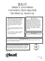
RX15
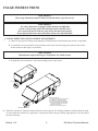
DIRECT GAS-FIRED
Construction HEATER
TECHNICAL MANUAL
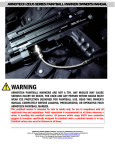
mGeneral Hazard WARNING:
Failure to comply with the precautions and
instructions provided with this heater, can
result in death, serious bodily injury and
property loss or damage from hazards of
fire, explosion, burn, asphyxiation, carbon
monoxide poisoning, and / or electrical
shock.
Only persons who can understand and follow the instructions should use or service this
heater.
If you need assistance or heater information
such as an instructions manual, label, etc.
contact the manufacturer.
mWarning:
Fire, burn, inhalation, and explosion
hazard. Keep solid combustibles, such as
building materials, paper, or cardboard,
a safe distance away from the heater as
recommended by the instructions. Never
use the heater in spaces which do or may
contain volatile or airborne combustibles,
or products such as gasoline, solvents,
paint thinner, dust particles or unknown
chemicals.
mWarning:
Not for home or recreational vehicle use.
FOR YOUR SAFETY:
The use and storage of gasoline or other flammable vapors and liquids in open containers in the
vicinity of this appliance is hazardous.
This heater is designed and approved for use as a construction
heater in accordance with standard ANSI Z83.7 • CGA 2.14.
CHECK WITH YOUR LOCAL FIRE SAFETY AUTHORITY
IF YOU HAVE QUESTIONS ABOUT APPLICATIONS.
®
Made in the USA
Heat
TM
RX-TM-0909
RX15
09/11/09
LIMITED WARRANTY
Cambridge Engineering, Inc. (“Manufacturer”) warrants its products (“the Products”) to be free from defects in
material and workmanship. Manufacturer’s Rx-Series Products shall be warranted for a period of 12 months from the
date of shipment, except that burner assemblies are warranted for five years from date of shipment.
Buyer’s sole and exclusive remedy for any nonconformity with this warranty shall be, at Manufacturer’s
option, repair or replacement of nonconforming parts, provided that Buyer shall return to Manufacturer, shipping prepaid, said non-c o n f o r m i n g part(s) bearing a durable tag indicating the Serial Number of the Product from
which the part was taken. In addition, Manufacturer may opt not to repair or replace nonconforming Product
or part(s), but instead may refund to Buyer the price thereof, in lieu of repair or replacement. In no event shall
Manufacturer be liable for more than a refund of the purchase price or replacement value of the Product or
part(s), whichever is less. This Warranty does not apply to field labor charges.
This Warranty does not apply and shall be void as to any Products that are misused or misapplied, that are
installed, operated or maintained not in conformity with Manufacturer’s design, specifications, instructions, or
Technical Manual, or are installed, operated or maintained in violation of any applicable national or local codes
or industry standards.
Manufacturer does not warrant Products, if they are abused, improperly operated or maintained, subjected to
abnormal wear and tear, damaged due to improper gas or electric service, damaged in transit, or that have been
repaired or modified by others without Manufacturer’s written authorization.
Buyer shall have no right to enforce this Warranty unless it has complied with all of its obligations under the
contract for purchase/lease of the Products, including without limitation, being current on all payment terms.
THIS LIMITED WARRANTY IS MANUFACTURER’S ONLY WARRANTY WITH RESPECT TO THE
PRODUCTS, AND IT IS IN LIEU OF AND SUPERSEDES ANY AND ALL OTHER WARRANTIES OF
ANY KIND WHATSOEVER, WHETHER WRITTEN, ORAL OR IMPLIED, INCLUDING WITHOUT
LIMITATION ANY IMPLIED WARRANTIES OF MERCHANTABILITY OR FITNESS FOR A PARTICULAR
PURPOSE. THE REMEDIES AFFORDED BUYER BY THIS WARRANTY ARE THE ONLY REMEDIES
AFFORDED BUYER FOR ANY NONCONFORMITY WITH THIS WARRANTY OR FOR ANY
DEFECT IN PRODUCTS, SERVICES, OR REPRESENTATIONS PROVIDED BY MANUFACTURER
IN CONNECTION WITH SUCH PRODUCTS. IN NO EVENT SHALL MANUFACTURER BEAR
ANY LIABILITY FOR INCIDENTAL OR CONSEQUENTIAL DAMAGES OF ANY KIND WHATSOEVER,
INCLUDING WITHOUT LIMITATION PERSONAL INJURY (INCLUDING DEATH), PROPERTY
DAMAGE, LOST PROFITS OR OTHER ECONOMIC LOSS.
Buyer acknowledges that the foregoing warranty, limitations, and exclusions are a reasonable allocation of
commercial risks by and among sophisticated business entities and are not subject to dispute as to their commercial reasonableness, fairness or ability to satisfy the essential purposes of the parties’ transaction.
Cambridge Engineering, Inc, has a continuous product improvement program; it reserves the right to change
design and specifications without notice.
Copyright 2008
All Rights Reserved
RxHeat, LLC
760 Long Road Crossing Dr.
Chesterfield, MO 63005
Phone: (877) 432-8297, Fax: (636) 898-3438
www.RxHeat.com
RX15
Direct Gas-Fired
Construction Heater
Technical Manual
Index
Page
Hazard Summary . . . . . . . . . . . . . . . . . . . . . . . . . . . . . . . . . . . . . . . . . . . . . . . . . . . . . . 2
Typical System Description . . . . . . . . . . . . . . . . . . . . . . . . . . . . . . . . . . . . . . . . . . . . . . 3
Component Identification . . . . . . . . . . . . . . . . . . . . . . . . . . . . . . . . . . . . . . . . . . . . . . . . 4
Accessory Options . . . . . . . . . . . . . . . . . . . . . . . . . . . . . . . . . . . . . . . . . . . . . . . . . . . . . . 5
Usage Instructions . . . . . . . . . . . . . . . . . . . . . . . . . . . . . . . . . . . . . . . . . . . . . . . . . . . . 6-10
Wiring Diagram . . . . . . . . . . . . . . . . . . . . . . . . . . . . . . . . . . . . . . . . . . . . . . . . . . . . . . . 11
Supply Pressure Requirements . . . . . . . . . . . . . . . . . . . . . . . . . . . . . . . . . . . . . . . . . . . . 14
Gas Train Components . . . . . . . . . . . . . . . . . . . . . . . . . . . . . . . . . . . . . . . . . . . . . . . . . . 15
Electrical Components . . . . . . . . . . . . . . . . . . . . . . . . . . . . . . . . . . . . . . . . . . . . . . . . . . 16
Component Parts List . . . . . . . . . . . . . . . . . . . . . . . . . . . . . . . . . . . . . . . . . . . . . . . . . . . 17
Replacements Parts & Service . . . . . . . . . . . . . . . . . . . . . . . . . . . . . . . . . . . . . . . . . . . . 18
Maintenance Instructions . . . . . . . . . . . . . . . . . . . . . . . . . . . . . . . . . . . . . . . . . . . . . 19-20
Disassembled View of ASCO Valve . . . . . . . . . . . . . . . . . . . . . . . . . . . . . . . . . . . . . . . 21
Troubleshooting Guide . . . . . . . . . . . . . . . . . . . . . . . . . . . . . . . . . . . . . . . . . . . . . . . 22-26
Minimum Fire Adjustment Procedure . . . . . . . . . . . . . . . . . . . . . . . . . . . . . . . . . . . . . . 27
Maintenance Log . . . . . . . . . . . . . . . . . . . . . . . . . . . . . . . . . . . . . . . . . . . . . . . . . . . 28-29
Copyright 2008
All Rights Reserved
RxHeat
760 Long Road Crossing Dr.
Chesterfield, MO 63005
Phone: (877) 432-8297, Fax: (636) 898-3438
www.RxHeat.com
HAZARD SUMMARY
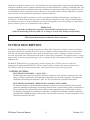
Hazard Identification
Warnings and Cautions appear at appropriate sections throughout this manual. Read these carefully.
mWARNING:Indicates a potentially hazardous situation which could result in
death or serious injury.
mCaution:Indicates a potentially hazardous situation which may result in
minor or moderate injury. It may also be used to alert against
unsafe practices.
Caution:Indicates a situation that may result in accidents with equipment or
property damage only.
The following safety precautions apply to the operation and maintenance of the equipment described by this
technical manual.
mWARNING:
Any unauthorized modification of this equipment shall void warranty.
mWARNING:
Operation, service, and repair of this equipment could result in exposure to electrical,
mechanical or other potential safety hazards and should only be performed by qualified personnel.
Use extreme caution and observe safety regulations at all times.
mWARNING:
Recirculation of room air is not permitted.
Lack of proper ventilation air will lead to improper combustion. Improper combustion
can lead to carbon monoxide poisoning leading to serious injury or death. Symptoms of
carbon monoxide poisoning can include headaches, dizziness and difficulty breathing.
mWARNING:
All factory provided lifting lugs must be used when lifting any unit. Failure to comply with this
safety precaution could result in property damage, serious injury or death.
RxHeat, LLC
2
RX-Series Technical Manual
This heater is designed for outdoor use only. It is intended for use in providing portable, temporary heat to buildings under
construction, alteration or repair. Adequate ventilation must be provided while heater is operating. Combustible solids, such
as building materials, paper or cardboard must be kept a minimum of 6 inches from the sides and top of the heaters, 0 inches from the bottom. Never use this heater in spaces which do or may contain volatile or airborne combustibles, or products
such as gasoline, solvents, paint thinner, dust particles or unknown chemicals.
Adequate building relief shall be provided so as to not over pressurize the building when this heater is operating at its
rated capacity. It should be noted that this can be accomplished by taking into account, through standard engineering methods, the structure’s designed infiltration rate, by providing properly sized relief openings, by interlocking a
powered exhaust system or by a combination of these methods.
Important:
If in doubt regarding heater operation, contact RxHeat Customer Service Group at
1-800-473-4569 during the hours of 8:00 a.m. to 5:00 p.m. Central Time, Monday through Friday.
These instructions must be retained for future reference.
SYSTEM DESCRIPTION
The RxHeat® RxHeat Heater, with high temperature rise Blow-Thru® Technology, includes a control system that is
designed to electronically modulate the gas flow using an amplifier, discharge temperature sensor and heat adjustment dial. The discharge temperature sensor, which is mounted in the heater’s discharge air stream, transmits a
resistance signal back to the amplifier that corresponds to the discharge temperature. The amplifier creates a voltage
output to drive an electronic proportioning gas valve to maintain the pre-selected temperature that is set on the heat
adjustment dial.
The RxHeat® RxHeat Heater is provided with a variable frequency drive (VFD) to allow for variable air
volume between 4000 and 6000 CFM. The VFD air volume control is located in the operator interface panel.
The VFD also limits the fan motor inrush current, allowing the heater to be powered by generator.
CONTROL SYSTEMS:
Electronic Discharge - Local (EDL)
The EDL temperature control system utilizes a discharge temperature sensor, which is mounted at the unit’s discharge, to transmit a signal back to the amplifier that corresponds to the discharge temperature. This permits the
adjustment of the discharge air temperature (120°F to 170°F) from the heater’s operator interface panel.
ELECTRONIC DISCHARGE - REMOTE SPACE MODULATION (EDSM)
The Electronic Discharge w/ Space Modulation temperature control has two modes of operation. The first mode
permits the adjustment of the discharge air temperature from the heater’s operator interface panel as described above.
The second mode utilizes a Remote Space Sensor (RSS), located in the heated space, which transmits a signal to
the amplifier to maintain the user-defined space temperature. The RSS allows the heater to modulate between programmed MAX and MIN parameters, factory preset to 210˚F and 40˚F respectively. The space temperature is field
adjustable between 60˚F and 140˚F.
RX-Series Technical Manual
3
RxHeat, LLC
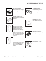
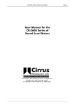
COMPONENT IDENTIFICATION
Unit shown with Accessory Options
Control Interface
& Disconnect
18" Discharge
Deflector
Lift Eye
18" Duct
Adapter
Fork Pockets
Duel Fuel
Gas Inlet
(NG/LP)
Operator
Interface
Electrical Power
Connection
RxHeat, LLC
4
RX-Series Technical Manual
Accessory Options
18" Discharge Deflector:
Factory installed option. Includes
turning vanes. Attaches directly
to the discharge of the unit.
Mat:
Weight:
REV NOW: A1
6952-900 Literature
ALL FORMED VIEW DIM'S MEASURED
FROM OUTSIDE UNLESS OTHERWISE NOTED.
REVISION
1
CS 1200 Partial Downturn
ASYMMETRICAL FEATURE
No.
18" Discharge Adapter:
Optional discharge elbow attachments used to easily connect flexible duct for distribution of air
into the building.
Date
Ecn
No.
Date
Chesterfield, Missouri
Ecn
WHERE USED:
MDL:
DWG:
DATE:
This is an instrument of service and is the sole property
of Cambridge Engineering, Inc. It may not be copied,
reproduced, or re-used on any other project without
agreement in writing from this company.
Unit Base Assembly: Factory
installed option with integral fork
lift pockets.
RSS (Remote Space Sensor)
Remote Space Sensor and
Thermostat: For use in EDSM
mode. RSS should be mounted
in the heated space, where it
modulates the heater's discharge
temperature to maintain a user
defined space temperature. RSS
attaches to the heater at the interface on the Operator Control door
and is supplied with a plug and
75' of cord.
OT Remote
Operating Thermostat for use
in EDL mode. The OT should
be located in the heated space,
where it acts to turn the heat ON
and OFF to maintain user defined
space temperature. In order to utilize the OT, the Blower Service
must be put in the "REMOTE"
position.
RX-Series Technical Manual
5
Rainhood: Factory installed
option with integral bird screen.
Caster Set: Provides on site
mobility without the use of heavy
machinery. Must be used with
optional base assembly.
Power Cord: 75ft., 10 gauge,
4 wire twist lock connector.
RxHeat, LLC
Usage INSTRUCTIONS
mWARNING:
These usage instructions must be followed each time heater is put into service.
mWARNING:
For safety, this heater is equipped with a manual reset high limit
switch, an air-proving switch and redundant electric shut-off valves.
Never operate the heater with any safety device that has been bypassed.
Do not operate this heater unless all of these features are fully functional.
__1. VISUAL INSPECTION AND PLACEMENT OF EQUIPMENT
A. Check for any physical damage from shipping or installation that could render heater unsafe or inoperable.
B. Locate heater on level ground in close proximity to the target area and engage the optional caster wheel
brakes located on the wagon’s rear wheels.
mCaution:
Manufacturer requires the usage of “stop blocks” for added security.
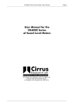
C. If applicable, open the heater’s rain hood assembly per the figure below.
Latch
1
2
4
Rain Hood Setup
1. Turn latch to release top panel.
2. Raise rain hood top panel.
3. Swing open right side panel.
4. Retract spring pin and position
top panel on side panel and
release spring pin.
5. Repeat 3 & 4 for left panel.
3
Spring Pin
D. I nstall the optional 18" diameter round flexible duct to the optional 18" discharge adaptors and then attach the adaptor to the optional air deflector, if applicable. Using the provided worm gear clamps, appropriately secure the duct to
the unit's discharge.
RxHeat, LLC
6
RX-Series Technical Manual
mWARNING:
This unit is designed to operate using Natural Gas or Liquid Propane (LP).
Failure to follow proper procedures with Natural Gas or LP can lead to fires, explosions,
personal injury or death. To ensure proper operation and prevent damage
to the unit and bodily injury the following instructions must be followed.
__2. GAS PIPING INSTALLATION
IMPORTANT
For a heater for connection to natural gas, the installation shall conform with local codes or,
in their absence, with the National Fuel Gas Code ANSI Z223.1/NFPA 54 and
the Natural Gas and Propane Installation Code, CSA B149.1.
For a heater for connection to Liquid Propane gas (LP) installation must conform with local codes or,
in their absence, with the Standard for the Storage and Handling of Liquefied Petroleum Gases,
ANSI/NFPA 58 and the Natural Gas and Propane Installation Code, CSA B149.1.
Steps B, C and D apply to a heater operating on Liquid Propane gas (LP).
mWARNING:
Verify the gas supply pressure complies with the heater nameplate.
A. Ensure the manual shut-off valve on the heater’s external gas train is closed. Verify the unions in the gas
piping are tight.
B. A
minimum of four (4) 100 lb LP cylinders manifolded
together, or one (1) 250 gallon LP tank is required to
operate heater. Supply cylinders must be designed,
fabricated, tested and marked in accordance with
regulations of the U.S. Department of Transportation,
Canadian Transport Commission or the Interstate
Commerce Commission, and must be arranged to
provide for vapor withdrawal from the operating
cylinder(s).
Typical LP Supply Cylinder Assembly
Pigtails
First Stage
Regulator
POL Fittings
Female Quick
Disconnect
Fitting
Hand Shut-off
Valve
Supply Cylinders
IMPORTANT:
If four (4) 100 lb LP cylinders are used, they shall only be used down to 30% fill capacity,
below which they may not allow the heater to operate at rated capacity.
C. LP cylinders must have a pressure regulator rated for at least 1,500,000 Btu/hr at 2 psi to 10 psi
outlet pressure (located downstream of the last cylinder if multiple cylinders are manifolded together).
A 1” female quick disconnect fitting shall be located downstream of the supply cylinder assembly
pressure regulator(s).
mWARNING:
The heater must be located at least 10 feet from any propane gas container. The heater’s discharge air
shall not be directed toward any propane gas container within 20 feet.
RX-Series Technical Manual
7
RxHeat, LLC
mWARNING:
The hose assembly must be visually inspected prior to each use of the heater. If it is evident there is excessive abrasion or wear, or the hose is cut, it must be replaced prior to the heater being put into operation. The
replacement hose assembly shall be 1” ID thermo-rubber gas connector with 1” male NPT on each end.
D.Connect the gas hose assembly provided with the heater between the LP cylinder(s) and the gas train.
E. Slowly open gas supply valve(s) to allow pressure in manifold assembly to equalize.
mWARNING:
• Do not use open flame (matches, torches, candles, etc.) in checking for gas leaks.
• Use only approved leak detectors.
• Failure to follow this warning can lead to fires or explosions.
• Fires or explosions can lead to property damage, personal injury or death.
F. Check all connections for gas leaks using approved gas leak detectors. Gas leak testing is performed
as follows:
• Check all pipe connections, hose connections, fittings and adapters upstream of the gas supply inlet
connection with approved gas leak detectors.
• In the event a gas leak is detected, check the components involved for cleanliness and proper application of pipe compound before further tightening.
• Further tighten the gas connections as necessary to stop the leak.
• Close the access and control panel doors and lock (reverse procedure from item E above)
• Close the external manual shut off valve.
• After all connections are checked and all leaks are stopped, proceed to next step.
__3. ELECTRICAL INSTALLATION
mWARNING:
Before attempting electrical installation, review the following instructions and wiring and connection
diagrams to make sure you have a thorough understanding of what is required.
mWARNING:
This appliance is equipped with a three-prong (grounding) plug for your protection against shock hazard
and should be plugged directly into a properly grounded three-prong receptacle.
A. Check the heater nameplate to determine the voltage and amperage requirements. Deviation from nameplate voltage may impact heater performance or cause damage to the heater.
B. Install the supply wiring, adequate Branch Circuit Protection, and electric grounding in compliance with
the National Electric Code ANSI/NFPA 70 or the Canadian Electrical Code C22.1, Part I.
mCAUTION:
Ensure that the supply voltage to the heater is within +/- 10% of the nameplate voltage.
RxHeat, LLC
8
RX-Series Technical Manual
__4. PREPARATION & START-UP INSTRUCTIONS
A. Verify that the field wiring, both primary and control, has been installed according to the RxHeat wiring
diagram, National Electrical Code, and local electrical codes.
B. Ensure that the rain hood, if applicable, is locked open and the discharge accessories are securely attached.
If applicable, engage the caster brakes and stop blocks.
C. Switch the voltage selector switch (see p. 13) to either 208V or 240V depending on the field wired voltage.
D. Turn the unit’s Disconnect Switch to the “ON” position.
mWARNING:
When disconnect switch is activated with the access doors open, live power is present.
Only experienced technicians with knowledge and respect for live power should proceed beyond this point.
E. Adjust airflow to desired level using the Air Volume Control dial. When using ducting, ensure that bends
are kept to a minimum.
F. Turn the RxSmart™ Selector switch to the “LOCAL” position.
G. Turn the Blower Operating Switch to the “ON” position. The VFD will energize and the blower speed will
slowly increase until operational speed is achieved.
H. Open internal and external manual shut-off valves located on the heaters gas train.
I. Turn the Burner ON-Off switch (located on the Control Door) to the “ON” position. The ignition sequence
will begin and the burner “ON” light will energize.
IMPORTANT:
It is normal for air to be trapped in gas hose on new installations. The heater may require
more than one trial for ignition before air is finally purged from line and ignition takes place.
Should the burner “ON” light de-energize, cycle the Burner ON-OFF switch.
All heaters are equipped with a Low Temperature Cutoff (LTC) safety system. This system will shut off the
blower at ambient temperatures below 50˚F (10˚C) if the blower operates for over 60 seconds without the burner operating. This shutdown is shown by the amber LTC Reset Light (see p13) on control panel. Should this
indicator light come on, cycle the Burner ON-OFF switch to reset.
J. With the burner operating, spray the complete gas train and supply piping with leak detector solution,
checking all pipe connections and plugs.
mWARNING:
All gas leaks detected must be repaired before heater is placed into service.
K. Adjust the temperature to the desired level using the Temperature Select Dial. Adjust the blower speed to
the desired airflow level using the Air Volume Control.
L. Turn the Burner “ON-OFF” switch to the “OFF” position.
M. Turn the unit’s Disconnect Switch to the “OFF” position.
RX-Series Technical Manual
9
RxHeat, LLC
N. Using the “Local/Remote” Mode RxSmart™ Switch located on the Operator Interface Panel (see pg. 13),
select the unit’s control system mode.
O. When utilizing the “REMOTE” control system, connect the RSS to the RSS Interface using the Remote
Space Sensor male connector.
P. Select the desired room temperature using the “Up” and “Down” arrows on the Remote Space Stat.
Q. Close and secure the Access and Control Panel Doors.
R. To restart unit for normal operation, turn unit’s Disconnect Switch to the “ON” position.
S. Turn the Burner “ON-OFF” switch to the “ON” position.
T. If applicable, press the Natural Gas Select switch.
mWARNING:
This unit is designed to operate using Natural Gas or Liquid Propane (LP).
Failure to follow proper procedures with Natural Gas or LP can lead to fires, explosions,
personal injury or death. To ensure proper operation and prevent damage
to the unit and bodily injury the following instruction must be followed.
__5. HEATER SHUTDOWN AND STORAGE
A. Close LP supply cylinder valve(s) or NG supply valve. The gas must be turned off at the LP supply
cylinder(s) or NG supply when the heater is not in use.
B. Allow the heater to burn off any fuel gas remaining in the gas supply line. Turn the the Burner “ON- OFF”
switch to the “OFF” position. Close appropriate manual shut-off valve on the heater’s external gas train.
C. Turn the heater Disconnect switch to the “OFF” position.
D. Disconnect the electric supply. Disconnect the gas supply piping from the heater’s external connection.
Seal all gas supply inlets to prevent the entry of debris.
E. Remove any attached flexible duct. Close rain hood assembly.
F. When the heater is stored indoors, the connection between the propane supply cylinder(s) and the heater
must be disconnected and the cylinder(s) removed from the heater and stored in accordance with the
Standard for the Storage and Handling of Liquefied Petroleum Gases, ANSI/NFPA 58 and the Natural Gas
and Propane Installation Code, CSA B149.1.
mWARNING:
The gas supply hose assembly shall be protected from traffic, building materials and
contact with hot surfaces both during use and while in storage.
RxHeat, LLC
10
RX-Series Technical Manual
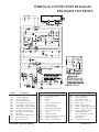
WIRING & Connection DIAGRAM EDL/EDSM Controls
SymbolDescription
AF
AMP
AVC
BOS
CR1
CR2
CR3
DISC
DTD DTS
FR
FSR
FOS
FU1
Air Flow Switch
Amplifier Solid State
Air Volume Control
Burner ON-OFF Switch
Control Relay - Gas Valve On
Control Relay - Gas Valve On
Control RElay - Call For Blower
Service Disconnect Non - Fused
Discharge Temperature Dial
Discharge Temperature Sensor
Flame Rod
Flame Safeguard Relay (HSI)
Fan Operating Switch
Fuse 24 Volt Control
RX-Series Technical Manual
SymbolDescription
FU2
Fuse 120 Volt Control
HL
High Limit
IG
Ignitor
L1
Power
L2
Light - Air Flow Proved
L3
Light - Burner On
L4
Light - Alarm (On)
L5
Light - Natural Gas Mode
LTC
Low Temperature Cutout
M
Motor
MV
Modulating Valve
OTOperating Thermostat (optional)
RES1 Resistor - Low Speed
RES2 Resistor - Propane Mode
11
SymbolDescription
RFS
RSS
SOV
SSV
SW1
SW2
SW3
SW4
SW5
T1
T2
TS
VFD
Relay - Fuel Switch
Remote Space Stat
Shut-off Valve - Gas
Safety shut-off Valve - Gas
Blower Service
Switch - SOV Leak Test
Switch - Operating Mode Selector
Switch - Voltage Select 208 / 230
Switch - Natural Gas Mode
Dual Output Transformer
Class 2 Transformer (24 Volt)
Temperature Sensor
(Part OFLTC)
Variable Frequency Drive
RxHeat, LLC
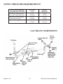
Supply Pressure Requirements
GAS SUPPLY PRESSURE
REQUIREMENTS TABLE
Minimum gas supply pressure
for maximum input adjustment
Minimum gas supply pressure
to maintain flame signal
Maximum gas supply pressure
NATURAL
GAS
LIQUID
PROPANE
20" wc
(50 mbar)
1.0" wc
(2.5 mbar)
10 PSI
(.69 bar)
5 PSI
(.35 bar)
1.0" wc
(2.5 mbar)
10 PSI
(.69 bar)
Gas Train Components
GAS TRAIN COMPONENTS
Supply Shut-off
Valve
4b
To Burner
Taps
forValve
Valve
Tap for
Leak
Leak Test
Test
Supply
Supply
Pressure
Pressure
Gauge
Gage
5
Supply
Inlet
4a
Drip Leg
Manual Burner
Shut-off Valve
1
Modulating
Valve
RxHeat, LLC
2
3 Appliance
Regulator
2
Shut-off
Valve
6
NPT Nipple
(Male Quick
Disconnect
Optional)
Safety
Shut-off
Valve
12
RX-Series Technical Manual
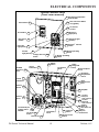
Electrical Components
Operator Interface Panel
(Panel cover removed)
Discharge Temperature
8 Selector Dial
RSS Interface 16
Nat. Gas Select Button
On (Lighted)
14
Air Volume
Control
10 Burner On
Light (Red)
OT Interface 17
Disconnect 15
Handle
11 LTC Reset Light
(Amber)
13b RxSmart
Switch
Power On
9a
Light (Green)
Class II
32
Transformer
TM
Selector
13a Burner Operating
Switch
Air Flow
9b
Light (Green)
Voltage Selector 12a
Switch
Variable
Frequency 20
Drive
18
12b Blower Operating
Switch
Airflow
23 Switch
T1 Terminal
Block
Flame
25 Safeguard
Relay
Burner Peephole
Cover
Discharge
26 Temperature
Sensor
31
Control
Transformer
High
27 Temperature
Limt
Control 30
Fuse 2
28 Amplifier
Control
Relay #1
Gas Valve On
Control
24b
Relay #2
Gas Valve On
Control
24d Relay #3
Gas Valve On
Control
24d Relay #4
Fuel Selector
24a
Control 29
Fuse 1
Control Relay #5
Voltage Select
24e
208/230
Low Temp
33
Cutout
T2 Terminal
Block
Disconnect 19
RX-Series Technical Manual
13
22 Leak Test
Switch
21 Blower Service
Switch
RxHeat, LLC
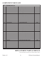
Component parts List
RX15 Component Parts List
Item
1
2
3
4a.
4b.
5
6
7
8a
8b
9
10
11
12a
12b
13
14
15
16
17
18
19a
19b
20
21
22
23
24
25
26
27
28
29
30
31
-
-
-
-
-
-
-
-
Location (Manual Page)
Gas Train
Gas Train
Gas Train
Gas Train
Gas Train
Gas Train
Gas Train
Operator Interface
Operator Interface
Operator Interface
Operator Interface
Operator Interface
Operator Interface
Operator Interface
Operator Interface
Operator Interface
Control Enclosure
Control Enclosure
Control Enclosure
Control Enclosure
Control Enclosure
Control Enclosure
Control Enclosure
Control Enclosure
Control Enclosure
Control Enclosure
Control Enclosure
Control Enclosure
Control Enclosure
Control Enclosure
Control Enclosure
Control Enclosure
Optional Control
Optional Control
Optional Control
Not Shown
Not Shown
Not Shown
Not Shown
Not Shown
Not Shown
Not Shown
Not Shown
Not Shown
Description
Valve - Gas Modulating M611 Valve - Gas Shut Off Regulator - Appliance lbs. to inches
Manual Burner Shut-Off Valve
Manual Supply Gas Shut-Off Valve
Gauge - Supply Pressure
Supply Gas Quick Disconnect - 1” NPT
DFTD (Temperature Selection Dial)
Burner On Light LP (Red)
Burner On Light NG (Green)
Switch - Natural Gas Select
Air Volume Controller
Burner On - Off Switch
Power Junction Box
Power Inlet, Twist Lock (Optional)
Disconnect Handle
Disconnect 60A Non-Fused
VFD 5HP 230v 1ph
Switch - Blower On - Off
Switch - SOV Leak Test (Momentary)
Airflow Switch
Control Relay - Gas Valve ON
Control Relay - Gas Valve ON
Control Relay - Fuel Select
Flame Safeguard Relay
Discharge Temperature Sensor
Switch - High Temp Limit - 250°F
Amplifier - Solid State (DFC-1)
Control Fuse 6.25 amp
Control Fuse 1.6 amp
Transformer Dual Output 350 va
Transformer Class 2 40va
Remote Space Sensor Female Connection
Optional Thermostat Connection Optional Control Mode Selection Switch
Remote Space Sensor Male Connection
Room Space Sensor
50 ft. LP Supply Hose 1” NPT
Gas Quick Disconnect - Female 1” NPT
Flame Rod
Igniter - 24v Hot Surface
18" Dia. Flexible Duct - Length 25 ft.
4 ft. Power Cord
75 ft. Power Cord
Part Number
24-033
21-118
24-008
24-020
24-115
23-633
44-123
23-016
22-602
22-601
22-295
22-104
22-107
6940-939
22-127
22-276
22-272
23-905
22-040
22-762
21-125
22-761
22-761
22-295
21-142
23-220
23-168
23-217
22-019
22-078
22-111
22-678
22-529
22-526
22-138
22-528
23-107
44-124
44-125
21-062
21-097
44-133
19-06969
19-06904
REPLACEMENT PARTS & SERVICE
Contact the RxHeat Customer Service Group at (800) 473-4569.
RxHeat, LLC
14
RX-Series Technical Manual
MAINTENANCE INSTRUCTIONS
mWARNING:
MAINTENANCE INSTRUCTIONS
The heater area must be kept clear and free from combustible
materials, gasoline, and other flammable vapors and liquids.
The flow of combustion and ventilation air must not be obstructed.
mWARNING:
Place the heater disconnect switch in the “OFF” position when performing service or
maintenance functions. Heater surfaces are hot for a period of time after the heater
has been shut down. Allow heater to cool before performing service, maintenance
or cleaning. Failure to follow this warning will result in burns causing injury.
Important:
The heater should be inspected before each use, and at least
annually by a qualified service technician.
BLOWER BEARING LUBRICATION
The RX15 model heaters require lubrication on intervals of 3 to 6 months. Use Shell “Alvania #2” Exxon “Unirox
N2” Mobil “532”, Mobil “Mobilux #2”, Texaco “Multifak #2”, Texaco “Premium RB” lubricants.
MOTOR BEARING LUBRICATION
Motors are pre-greased normally with Shell “Dolium R”. Equivalent greases which are compatible with the motor furnished grease are Chevron “SRI No. 2” and Texaco “Premium RB”.
HOURS OF SERVICE PER YEAR
Motor Frame Size
5000 Hours
Continous Normal Application
Seasonal Service Motor Is Idle For
6 Months Or More
SUGGESTED RELUBE INTERVAL
NEMA FRAME SIZE
42 to 215T
5 years
2 years
1 year (Beginning of
1 year
(Beginning
of Season)
Season)
Continous High Ambients, Dirty Or Moist
Locations, Or High Vibration
6 months
BELT TENSIONING
Using a Browning Belt Tension Checker and a straight edge, attain proper tension according to the following table:
RX15
0.25 (1/4)”
3 -5 lbs
2.5 - 4 lbs
Periodic belt adjustments may be required. Indications of loose belts include barking or squealing when the blower starts.
RX-Series Technical Manual
15
RxHeat, LLC
Electric Shut-off VALVE LEAK CHECK
mWARNING:
The heater shall be periodically evaluated, at least annually, for the seal tightness
of the electric shut-off valves.
he heater is equipped with a leak test facility to assist in checking these seals. A momentary switch and a gas port
T
for measuring pressure between valves are provided as the leak test hardware. The procedures for the electric shut-off
valve leak check are as follows.
A. Connect a 0 to 10 inches water column (" wc) manometer to the 1/8" NPT tapped fitting located just prior
to the burner. Verify the manometer is properly zeroed.
B. To check the tightness of second electric shut-off valve (SSV), close the manual burner shut-off valve,
hold the momentary leak test switch in the closed position and wait 30 seconds to read the manometer. If the
reading is greater than 0" wc, refer to the Maintenance Instruction Section for information on Gas Valve
Cleaning for the second electric shut-off valve (SSV) and retest. If reading is 0" wc, remove the manometer, install the pipe plug and open the manual burner shut-off valve.
C. To check the gas tightness of the first electric shut-off valve (SOV) in the gas train, connect the manometer to the leak test port between the valves and wait 30 seconds to read the manometer. If the reading is
greater than 0" wc, refer to the Maintenance Instruction Section for information on Gas Valve Cleaning for the
first electric shut-off valve and retest. If reading is 0" wc, remove the manometer and install the
pipe plug.
mWARNING:
Do not wash the interior of the heater. Use only compressed air, a soft brush
or a dry cloth to clean the interior of the heater and its components.
BLOWER CLEANING
The blower wheel should be examined for accumulation of dust on the blades. These surfaces must be kept clean.
Dirt accumulation will result in significant air flow reduction and/or possible imbalance of the blower wheel.
CAUTION:
Prolonged imbalance can result in catastrophic failure of the blower wheel and other related components.
BURNER CLEANING
The RxHeat burner is for the most part self-cleaning. However, if the application is extremely dirty or subject to
heavy insect infestation, it may become necessary to periodically clean the burner. Remove and clean the burner in
accordance with the following recommended procedures:
A. Turn the heater disconnect switch to the “ OFF” position. Close the manual burner shut-off valve.
B. Loosen the union in the gas train.
RxHeat, LLC
16
RX-Series Technical Manual
CAUTION:
Igniter is made of silicon carbide material and should be handled with care to avoid breakage.
C. Disconnect the ignition cable from the burner and then remove the flame rod.
D. Examine the flame rod ceramic for cracks and replace if necessary. Clean dirt/grime build-up from the
insulator. E. Remove the fasteners that secure the burner to the housing. The burner will then be free to slide out.
m
CAUTION:
Be sure to take necessary safety precautions
(such as wearing eye protection, etc.) before attempting this step.
F. Clean the burner by back-flushing using high pressure air (40-80 psi). Continue back-flushing until dust
and debris has been completely expelled from the burner. Wipe all burner surfaces with a cloth to remove
any foreign matter.
m
CAUTION:
Cleaning the burner and the burner orifice with anything other than
compressed air may drastically affect heater performance.
G. Perform Discharge Air Temperature Sampling Tube cleaning at this time.
H. Reassemble the burner using the above steps in reverse order.
DISCHARGE AIR TEMPERATURE SAMPLING TUBE CLEANING
With the Burner out of the unit, clean the Discharge Air Temperature Sampling Tube located inside the unit. The
Sampling Tube is located inside the discharge duct beyond the stainless steel burner extension(s). Clean the Sampling
Tube using high pressure air (40-80 psi) until all debris is completely removed from the Tube.
Electric Shut-Off VALVE CLEANING
All solenoid valves should be cleaned periodically. The time between cleanings will vary depending on the medium
and service conditions. In general, if the voltage to the coil is correct, sluggish valve operation, excessive noise, or
leakage will indicate that cleaning is required.
mWARNING:
In the extreme case, faulty valve operation will occur and the valve may fail to open or fully close.
IMPORTANT:
It is not necessary to remove the valve from the pipeline for cleaning.
mWARNING:
To prevent the possibility of severe personal injury or property damage, turn off electrical power, close
the upstream manual gas valve, depressurize valve, extinguish all open flames and avoid any type
of sparking or ignition. Vent hazardous or combustible fumes to a safe area before servicing the valve.
RX-Series Technical Manual
17
RxHeat, LLC
ASCO Gas Valves: Series 8214
Disassemble valve and clean all parts as follows:
Important: If parts are worn or damaged, install a complete ASCO Rebuild Kit.
A. Remove the solenoid enclosure.
B. Remove the bonnet screws, valve bonnet, bonnet gasket, core/diaphragm sub-assembly and body gasket.
C. All parts are now accessible to clean or replace.
D. Lubricate the bonnet gasket and body gasket with a light coat of DOW CORNING® 200 Fluid lubricant or
an equivalent high-grade silicone fluid.
E. Apply a light coat of RemGrit TFL 50® Dry Lubricant to: Valve seat; Valve body surface where the diaphragm assembly contacts the valve body and body gasket; and the internal surface of the valve
bonnet where the diaphragm assembly contacts the bonnet when the valve is in the energized (open position).
IMPORTANT:
If the valve has been disassembled for inspection and cleaning only and a Rebuild Kit is not being
installed, lubricate the following with RemGrit TFL 50® Dry Lubricant:
• Diaphragm assembly on both sides
• Main disc at base of core/diaphragm sub-assembly.
• Pilot disc at base of core assembly.
m
CAUTION:
Do not distort the hanger spring between core assembly and
the diaphragm assembly when lubricating pilot disc.
F. Replace the body gasket and the core/diaphragm sub-assembly with the closing spring attached. Locate the
bleedhole in the core/diaphragm sub-assembly approximately 30˚ CCW from the valve inlet.
G. Replace the valve bonnet and bonnet screws (6). Torque the screws in a crisscross manner to 100 ± 10
inch lbs. Replace the solenoid and make the electrical hookup.
mWARNING:
To prevent the possibility of severe personal injury or property damage, check valve for proper
operation before returning to service. Also perform a gas valve leak check and gas train leak check.
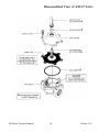
ORDERING INFORMATION FOR ASCO REBUILD KITS
Parts marked with an asterisk (*) in the exploded views are supplied in Rebuild Kits.
When ordering Rebuild Kits for ASCO valves, order the Rebuild Kit number stamped on the valve nameplate. If the
number of the kit is not visible, order by indicating the number of kits required, and the Catalog Number and Serial
Number of the valve(s) for which they are intended.
RxHeat, LLC
18
RX-Series Technical Manual
Disassembled View of ASCO Valve
RX-Series Technical Manual
19
RxHeat, LLC
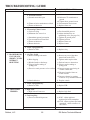
TROUBLESHOOTING GUIDE
PROBLEM
I. No Blower
Operation
POSSIBLE CAUSE
1. Heater Disconnect
a) Disconnect in “OFF” position
CORRECTIVE ACTION
a) Turn disconnect “ON”
2. Blower ON-OFF Switch
a) Switch in OFF position
a)Place switch in the “ON” position
b) Replace switch
b) Defective switch
3. Control Transformer
a) No input voltage
b) Blown control fuse
c) Defective transformer
4. Motor Protection
a) VFD in alarm
a)Check disconnect and
supply fusing
b) Replace control fuse
c) Replace transformer
a1) Check primary power source
a2) Cycle VFD with disconnect
a3) Reduce motor speed using
air volume control
b) Replace VFD
b) VFD defective
5. Motor
a) No input voltage
b) Improper voltage c) Defective motor
a) Check primary power source
b) Consult factory
c) Replace motor
6. Blower Damage
a) Defective or locked bearings
b) Check for physical damage
a) Replace bearings
b) Replace or repair blower
7. Belts
a) Belt slipping
b) Belt broken or missing
a) Tighten belts
b) Replace belts
II. Blower
1. Burner ON-OFF Switch
a) Switch in “OFF” position
Runs;
b) Defective Switch
No Heat;
a) Place switch in “ON” position
b) Replace Switch
Flame
Safety
2. Air Flow Switch a) Blower running backwards
a)Reverse any two of the three
Relay
motor leads to the VFD
Doesn’t
Lock Out
b) Belts slipping
b) Tighten and/or replace belts
c) Blocked intake or discharge
c) Find and remove obstruction
d) Clogged airflow tubing or d) Clean or replace tubing or
pickup ports pickup ports
e) Excessive static pressure or low airflow e1) Increase motor speed using air
volume control dial
e2) Decrease length of ducts or RxHeat, LLC
20
RX-Series Technical Manual
TROUBLESHOOTING GUIDE
PROBLEM
POSSIBLE CAUSE
CORRECTIVE ACTION
bends in ducts
e3) Increase exhaust by opening
windows or by mechanical means
f) Switch defective
f) Replace switch
3. Flame Safeguard Relay (FSR)
a) No input voltage
a) Check wiring
b) Defective FSR
b) Replace FSR
III.BLOWER RUNS;
1. Igniter
a) No current (open igniter)
NO HEAT;
b) No voltage
FLAME
SAFETY RELAY
LOCKS OUT
2. High Limit
a) High limit tripped
3. Electric Shut-off Valve
a) No input voltage
b) Gas valve does not open
c) Defective electric shut-off valve
4. Modulating Valve
a) Minimum fire set too low
5. Regulator
a) Clogged vent orifice
b) No supply pressure
c) Improper manifold pressure
d) Defective regulator
6. Burner
a) Burner defective
During trial for ignition:
a) Check igniter current (1.6 AMPS)
b)Check FSR output to igniter
(24 VAC)
a) See Problem Number VI
a1) Check FSR output to R1 relay during ignition trial
a2) Check electric shut-off valve
circuit and wiring
b1) Compare supply voltage to nameplate voltage
b2) Clean and/or replace electric
shut-off valve parts
c) Replace valve
a)Adjust minimum fire on
modulating valve ( See page 26)
a) Clean or replace orifice
b)Check manual shut-off valve
and piping
c) Adjust appliance regulator per
nameplate
d) Replace regulator
a) Replace burner
IV.BLOWER RUNS;
1. Low Flame Current (µΑ)
a) Dirt build-up on flame rod a) Clean dirt deposit from ceramic BURNER
ceramic
insulator
surface and install protective boot
lights;
b) Minimum fire set too low
b)Adjust minimum fire on
FLAME SAFETY
modulating valve (See page 26)
RELAY LOCKs
c) Flame rod defective
c) Replace flame rod
OUT
RX-Series Technical Manual
21
RxHeat, LLC
TROUBLESHOOTING GUIDE
PROBLEM
POSSIBLE CAUSE
d) Burner defective
2. No Flame Current
a) Ground connection open
b) Flame rod wire termination oxidized
c) Flame rod defective
CORRECTIVE ACTION
d) Replace burner
a1) Reference T1 transformer to
ground
a2) Tighten loose ground screws
b) Clean terminal and reinsert
c) Replace flame rod
3. Fluctuating Flame Current
a) Unit over firing
b) Minimum fire set too low
c) Intermittent ground connection
d) Loose terminal on Flame Rod
e) Flame rod defective
d) Burner defective
a) Check manifold pressure
b) Adjust minimum fire on
modulating valve (See page 26)
c) Tighten all ground points
d)Tighten jam nuts
e) Replace flame rod
d) Replace burner
4. Flame Safeguard Relay
a) Defective FSR
a) Replace relay
V. BLOWER RUNS;
1. Air Flow Switch a) Blower running backwards
UNIT HEATS;
a)Reverse any two of the three
motor leads to the VFD
SHORT CYCLES
b) Belts slipping
b) Tighten and/or replace belts
WITHOUT
c)
Blocked
intake
or
discharge
c) Find and remove obstruction
RESETTING
d) Clogged airflow tubing or d) Clean or replace tubing or
pickup ports pickup ports
e) Excessive static pressure or low airflow e1) Increase motor speed using air
volume control dial
e2) Decrease length of ducts or bends in ducts
e3) Increase exhaust by opening
windows or by mechanical means
f) Switch defective
f) Replace switch
2. Flame Safeguard Relay
a) Defective FSR
a) Replace FSR
VI. HIGH LIMIT
1. High Limit
a) High limit will not reset
TRIPPED
a) Replace high limit
2. Unit Overfiring
a) Excessive manifold pressure
RxHeat, LLC
22
a)If NG - adjust appliance
regulator per heater nameplate
a2) If LP - adjust regulator per heater
nameplate - check resistance of
the resistor
RX-Series Technical Manual
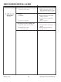
TROUBLESHOOTING GUIDE
PROBLEM
POSSIBLE CAUSE
3. Airflow Reduced
a) Blower running backwards
b) Belts slipping
c) Blocked intake or discharge
4. Temperature Control System
a) Temperature control system does not
modulate
VII.
1. Amplifier
MODULATING
a) Wire(s) not connected to amplifier VALVE b) Amplifier defective
DOES NOT
MODULATE;
2. Discharge Temperature Sensor
CONTINUOUS
a) Discharge air temperature sampling
HIGH FIRE
tube clogged
b) Open in sensor circuit
c) Sensor cross-wired to amplifier
3. Space Temperature Selector
(EDSM only)
a) Open in sensor circuit
b) Induced voltage in field wiring
c) Space sensor located improperly
4. Modulating Valve
a) Foreign material holding valve open
VIII.
1. Modulating Valve
MODULATING a) Valve coil is open or shorted
VALVE
DOES NOT
MODULATE;
CONTINUOUS
2. Class II Transformer
LOW FIRE
a) No voltage output to amplifier
3. Amplifier
a) No output voltage to valve
CORRECTIVE ACTION
a) Reverse motor direction
b) Tighten and/or replace belts
c) Find and remove obstruction
a) See problem VII
a) Re-install wire(s)
b) Replace amplifier
a) Clean Discharge Air Temperature Sampling Tube (see page 18)
b) Replace the sensor if the resistance measured at device exceeds
24,000Ω or is less than 7,000Ω.
c) Correct wiring terminations
a)Replace the sensor if the resistance of sensor circuit is less
than 7,000 Ω
b) Utilize shielded, twisted pair wiring
c) Remote space sensor in
cold draft - relocate
a) Replace valve
a) Replace valve if coil resistance
is less than 40 Ω or greater
than 85 Ω
a) Replace transformer
a) With the wire removed from
terminal 3 of amplifier, replace
amplifier if the valve voltage does
not exceed 18 volts DC.
RX-Series Technical Manual
23
RxHeat, LLC
TROUBLESHOOTING GUIDE
PROBLEM
POSSIBLE CAUSE
4.Discharge Temperature Sensor
a) Short in sensor circuit
CORRECTIVE ACTION
a) Replace the sensor if the resistance measured at device exceeds
24,000Ω or is less than 7,000Ω.
IX. ERRATIC OR 1. Amplifier
PULSATING a) Hunting
FLAME
a1)Adjust sensitivity control dial
counter-clockwise
a2) Clean discharge temperature
sensor
b) Defective Amplifier
b) Replace amplifier
2.Remote Space Sensor (EDSM only)
a) Induced voltage in field wiring
RxHeat, LLC
b) Remote space sensor located improperly
24
a)Utilize shielded, twisted pair
wiring
b) Sensor located in heated air
stream - relocate
RX-Series Technical Manual
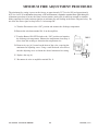
MINIMUM FIRE ADJUSTMENT PROCEDURE
The minimum fire setting is preset at the factory at approximately 25˚F rise for NG and approximately
40˚F rise for LP. If an adjustment is necessary, a DC microammeter is required to monitor flame signal during the
adjustment procedure to ensure the flame current remains steady and of sufficient strength to maintain
burner operation for both consistent ignition at minimum fire and locking in the flame safeguard relay. Do
not allow the flame signal to drop below 2.0 microamps DC.
A. Turn the Disconnect to the “ON” position and monitor the discharge temperature.
B. R
emove the wire from terminal No. 8 on the amplifier.
C. Turn the Burner ON-OFF Switch to the “ ON” position and monitor
the discharge air temperature. Subtract the temperature from Step A
above from this reading to determine the temperature rise.
D. Remove the cap (A), located on the front of the valve, exposing the
minimum fire adjusting screw. Using a small flat head screw driver,
turn the adjusting screw to obtain the desired minimum fire setting.
E. Replace the cap (A)
F. Reconnect the wire to amplifier terminal No. 8.
RX-Series Technical Manual
25
M611
RxHeat, LLC
MAINTENANCE LOG
MODEL NO.
Date
RxHeat, LLC
SERIAL NO.
Activity
26
Technician
RX-Series Technical Manual
Cambridge Engineering
760 Long Road Crossing Dr.
Chesterfield, MO 63005
RX-Series heaters are manufactured by Cambridge Engineering, Inc. which reserves the right to change specifications, modify the design and/or substitute equivalent materials without notice as the result of code requirements, product
enhancements, ongoing research/development and vendor changes beyond our control.
Copyright Cambridge Engineering, Inc. All Rights Reserved
Heat
TM
760 Long Road Crossing Dr.
Chesterfield, MO 63005
Ph: 877-HEAT-BY-RX
(87 7- 4 32- 82 97)
Fax: (636) 898-3438
www.RxHeat.com