1
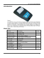
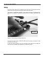
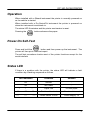
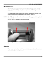
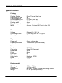
Electro-Magnetic Compatibility (EMC)
This product complies with Council Directive 2004/108/EC
when installed and used in accordance with the relevant
instructions.
Service and Technical Support
PLEASE CONTACT YOUR NEAREST DISTRIBUTOR
If unknown then fax: 44 (0) 1453 733322
© Copyright RDS Technology Ltd 2008
Document number
S/DC/500-10-570: Issue 1.01 : 11/8/08
\UK570101.DOC
User Guide
ICP 300
In-Cab Printer
Operation
1
ICP 300 IN-CAB PRINTER
Contents
Introduction____________________________________________3
Parts List_______________________________________________3
Setup _________________________________________________4
Operation ______________________________________________5
Power-On Self-Test _____________________________________5
Status LED _____________________________________________5
Replacing the paper roll_________________________________6
Maintenance ___________________________________________7
Service ________________________________________________7
Specifications __________________________________________8
2
ICP 300 IN-CAB PRINTER
Introduction
Figure 1
The RDS ICP 300 In-Cab printer is an ultra-compact thermal printer designed
for easy paper loading. It accepts 58mm wide rolls up to 44mm dia. The
printer is connected to and powered from the instrument via a single cable
with RJ-12 connector, and operates with a supply voltage in the range 1035V dc. No maintenance is required except to occasionally clean the rubber
paper roller to remove any dirt buildup.
Parts List
Part No
Description
Qty
S/HU/167-4-001
ICP 300 Printer
1
S/BK/167-4-015
Mounting Plate
1
S/CB/167-4-005 or:
Printer Cable for Wizard
1
S/CB/167-4-006
Printer Cable for Pro-Series/PSi
S/F701-050
M3X 8 Screw
2
S/F713-001
M3 Washer
2
S/FSNR/940117
M6 x 16 Hex Set Screw
2
S/FSNR/406
M6 Nut
2
S/FSNR/940205
M6 Washer
2
S/CBL/TIE/001
Cable Tie
25
S/AC/167-3-030
Paper Roll
2
3
ICP 300 IN-CAB PRINTER
Setup
Plug the printer cable RJ-12 connector into the back of the printer and then
attach the mounting plate with the two M3 screws provided.
The cable is connected normally to the upper port on a ‘Pro-Series’/’Psi’
head unit, or into the ‘Terminator’ junction box of a ‘Wizard’ instrument (fig.
2).
RED WIRE
Figure 2 Connecting to a Wizard Head Unit
Connect the lead Pt No. S/CB/167-4-005 onto the 4-way connector in the
terminal box as shown.
Locate the cable grommet onto the moulding, and cable-tie the head unit
lead onto the moulded cable saddle to provide strain relief.
4
ICP 300 IN-CAB PRINTER
Operation
When installed with a Wizard instrument the printer is normally powered on
as the vehicle is started.
When installed with a Pro-Series/Psi instrument the printer is powered on
when the instrument is switched on.
The status LED illuminates and the printer mechanism is reset.
Pressing the
button advances the paper.
Power-On Self-Test
Press and hold the
button and then power up the instrument. The
printer will then print a self-test report.
The self-test procedure checks most of the printer functions except for the
serial interface
Status LED
If there is a problem with the printer, the status LED will indicate a fault
condition by a flashing sequence as follows.
LED Indication
Condition
Solution
On
Normal
-
Off
No Power
-
Paper Out
Fit new paper
Print head too hot
Allow head to cool
Power below 10V dc
Check supply +V
*
*
*
**
**
**
***
***
***
5
ICP 300 IN-CAB PRINTER
Replacing the paper roll
Pull the lever up until the lid is released. Do not use excessive force.
Figure 3: Unlock paper compartment
Replace the roll and press the lid at each side until it clicks shut.
Figure 4: Lock paper compartment
6
ICP 300 IN-CAB PRINTER
Maintenance
Occasionally, it may be necessary to clean dust or foreign matter from the
paper compartment. Wipe the paper compartment clean using a dry soft
cloth only.
The rubber roller can be removed for cleaning if necessary. Push the roller
forwards at each end to disengage it from the slots (figure 5).
NOTE:
DO NOT angle the roller too far with one end still engaged as this may break
the moulding.
DO NOT touch or attempt to clean the print head.
Figure 5: Remove paper roller
Service
There are no servicable parts. In the event of damage or failure, the printer is
replaceable only as a complete unit.
7
ICP 300 IN-CAB PRINTER
Specifications
Printing
Printing System
Characters per line
Character matrix
Horizontal dot pitch
Vertical Dot pitch
Printing width
Max. print speed
MTBF
Direct Thermal line head
48
24 x 8
0.125mm (200 dpi)
0.125mm
48mm
10 lines per second
Approx. 107 lines (20°C, print ratio 25%)
Power
Voltage
Operating Current
Standby
External 10 – 35 V dc
From 1A @ 35V to 2.7A @ 10V
30 mA
Paper
Paper roll
Paper specification
58mm x 44mm dia
TF50-KS-E2D (recommended)
I/O
Interface
Connector
Baud rate
Parity
Data Bits
Stop Bits
Handshake
Buffer
Character set
RS232C
6-way RJ-12 socket
4800
None
8
1
Hardware (CTS)
5 Kbyte
ASCII
Environmental
Operating
Storage
Dimensions
Weight
8
0°C to +50°C
-20°C to +60°C
85.5mm x 150mm x 55mm (excluding bracket)
0.4 kg (excluding bracket)
ICP 300 IN-CAB PRINTER
Issue 1:
17/7/07
Original issue
Issue 1.01:
11/8/08
ref. p.3 Parts List
9